
 Open Access Article
 This Open Access Article is licensed under a Creative Commons Attribution-Non Commercial 3.0 Unported Licence
Characterisation of the magnetic response of nanoscale magnetic filaments in applied fields
Deniz
Mostarac
 *a,
Pedro A.
Sánchez
bc and
Sofia
Kantorovich
ab
*a,
Pedro A.
Sánchez
bc and
Sofia
Kantorovich
ab
aUniversity of Vienna, Vienna, Austria. E-mail: deniz.mostarac@univie.ac.at; Tel: +43-1-4277-73277
bUral Federal University, Ekaterinburg, Russia
cWolfgang Pauli Institute, Vienna, Austria
First published on 14th May 2020
Abstract
Incorporating magnetic nanoparticles (MNPs) within permanently crosslinked polymer-like structures opens up the possibility for synthesis of complex, highly magneto-responsive systems. Among such structures are chains of prealigned magnetic (ferro- or super-paramagnetic) monomers, permanently crosslinked by means of macromolecules, which we refer to as magnetic filaments (MFs). In this paper, using molecular dynamics simulations, we encompass filament synthesis scenarios, with a compact set of easily tuneable computational models, where we consider two distinct crosslinking approaches, for both ferromagnetic and super-paramagnetic monomers. We characterise the equilibrium structure, correlations and magnetic properties of MFs in static magnetic fields. Calculations show that MFs with ferromagnetic MNPs in crosslinking scenarios where the dipole moment orientations are decoupled from the filament backbone, have similar properties to MFs with super-paramagnetic monomers. At the same time, magnetic properties of MFs with ferromagnetic MNPs are more dependent on the crosslinking approach than they are for ones with super-paramagnetic monomers. Our results show that, in a strong applied field, MFs with super-paramagnetic MNPs have similar magnetic properties to ferromagnetic ones, while exhibiting higher susceptibility in low fields. We find that MFs with super-paramagnetic MNPs have a tendency to bend the backbone locally rather than to fully stretch along the field. We explain this behaviour by supplementing Flory theory with an explicit dipole–dipole interaction potential, with which we can take in to account folded filament configurations. It turns out that the entropy gain obtained through bending compensates an insignificant loss in dipolar energy for the filament lengths considered in the manuscript.
1. Introduction
Stimuli-responsive materials are one of the central research topics in modern soft mater physics.1,2 There is a broad spectrum of stimuli one can use to modify material properties, spanning temperature and electromagnetic radiation,3 pH,4 ionic strength,5 and specific additives and substances.6 Responsiveness to magnetic fields, however, proves to be of extraordinary potential, due to the dynamic control of intensity, great spatial resolution achievable with them, and the fact that magnetic fields do not interfere with biological tissues and processes.7 In attempts to capitalise on this potential came the idea to combine magnetic micro- and nanoparticles (MNPs) into liquids, gels or elastomers, forming a class of so-called magnetic soft matter. Within the context of magnetic soft matter, when talking about MNPs, one refers either to ferromagnetic or super-paramagnetic ones,8 whereas when micron sized, multi-domain particles are used, one has to distinguish between magnetically soft and hard ones.9 In fact, intrinsic magnetisation of micron sized, multi-domain particles, should be treated via micro-magnetic simulations.10 Over the years, a diverse landscape of magnetic soft mater systems emerged, based on MNPs and micron-sized monomers, including ferrofluids,11–14 ferrogels,15,16 elastomers,9,17–20 magnetic gels15,21,22 and magnetic filaments (MFs).23,24 As a consequence, nowadays there are recipes how to synthesise many of these systems with a desired macroscopic response. MFs, the subject of this manuscript, can largely be considered as analogous to polymer chains (though at a supra-colloidal scale) where the MNPs serve as polymer monomers and the crosslinkers play the part of chemical bonds between them. From the first attempts to synthesise MFs in which micron-sized magnetic-filled paramagnetic latex beads were used to form chains,25,26 the field has come a long way in both synthesis approaches and theoretical understanding. Permanent chains of DNA crosslinked, micrometre sized, super-paramagnetic monomers were in fact synthesised more than one decade ago, with the purpose to work as magnetically driven microfluidic swimmers.23 Nowadays, there is a plethora of methods to prepare MFs.24,27–41 Most existing crosslinking procedures for synthesis of such MFs are based on the functionalisation of the MNP surface.42 One-dimensional crosslinking of ferromagnetic MNPs has only been achieved in terms of rather rigid filaments or nanowires.40,43–48 Semi-flexible fibre structures of MNPs have been obtained instead by crosslinking them in bunches.49 Linear, filament-like assemblies of ferromagnetic nanoparticles have been made using biological agents and bio-templates.50,51 Magnetic nanochains have been made by causing chain-like assembly applying external magnetic fields on super-paramagnetic nanoparticle clusters, fixed by an additional layer of silica.52 In summary, one can divide available MF systems in two classes: those containing magnetisable (or super-paramagnetic) particles and those made of ferromagnetic particles. Besides that, one can also distinguish MFs by their rigidity. So far, flexible, nanoscale MFs, which have a finely controllable micro-structure, remain to be experimentally realised. However, recent advances in synthesis techniques, such as the ones based on programmable DNA–MNP assembly have shown promising results on route towards achieving exactly that.53–59 In recent years, MFs have found a growing range of applications.60–63 MFs with super-paramagnetic MNPs, albeit rather soft ones, have been experimentally investigated for artificial swimmer designs.64,65 Furthermore, they have proven useful in cellular engineering,66,67 and designs for biomimetic cilia.68,69Theoretically, the properties of MFs exposed to external magnetic fields have mostly been explored in bulk.70–77 MFs with super-paramagnetic MNPs have been theoretically investigated in artificial swimmer designs.78–80 In-field behaviour (i.e. buckling, coiling and bending) of MFs with super-paramagnetic MNPs has been investigated under multiple conditions,81,82 such as having the MFs grafted to a surface,83 or exposed to a rotating or fast precessing magnetic fields.84–86 MFs in general have proven very interesting as a basis for bio-medical application designs.87–89 Paramagnetic MFs have been investigated and characterised as potential micro-mixers,90 as well as for cargo capture and transport purposes.91
In spite of all of the previous studies, to the best of our knowledge, there are neither models that accurately account for super-paramagnetic behaviour of MNPs, nor comparative studies of nanosized MFs, with ferro- and super-paramagnetic MNPs, placed in multiple crosslinking scenarios, and exposed to an external magnetic field. We aim to provide a deeper insight into these questions with this work. In order to do so, we present four different computational models for MFs, together with a comparative analysis of their equilibrium magnetic and structural properties, in constant, homogeneous magnetic fields. Rather than making an attempt to explicitly model any particular crosslinking procedure, we put forward a simulation approach to model two distinct crosslinking scenarios, in a general and easily adaptable way, for both ferro- and super-paramagnetic MNPs. We achieve this by considering crosslinking scenarios where we impose mild or severe constraints on the translational and/or rotational degrees of freedom of the MNPs with respect to the filament backbone.
The paper is structured as follows: in section 2 we present the details of our coarse-grained bead-spring modelling approach, magnetic properties of MNPs, magnetic interactions, and the simulation method. We introduce two distinct crosslinking approaches, both for ferromagnetic and MFs with super-paramagnetic MNPs. We proceed to discuss our Results in section 3. We present how a choice of crosslinking approach and/or the magnetic nature of the monomers, affects the structural properties of the filament in subsection 3.1. We present a comprehensive analysis of the magnetic properties of MFs in subsection 3.2. In section 4, we provide analytical estimations of the free energy of MFs in order to explain simulation results previously reported in section 3.1 and 3.2. In section 4, we provide a short summary and prospects of our study.
2. Magnetic filaments in silico
2.1. Main interactions
In this work, we consider MFs formed by mono-disperse, magnetic particles – monomers, modelled as identical, spherical particles with a characteristic diameter σ. The soft core interaction between the monomers is given by the Weeks–Chandler–Andersen pair potential (WCA):92 | (1) |
| ULJ(r) = 4ε{(σ/r)12 − (σ/r)6} | (2) |
Monomers within our models can be either ferro- or super-paramagnetic. For ferromagnetic MNPs, we introduce point magnetic dipole moments  of fixed length
  , located at particle centres. We account for the long-range magnetic inter-particle interaction by means of the standard dipole–dipole pair potential:
 | (3) |
 , and
, and  is the displacement vector connecting the centres of monomers i and j with dipole moments
  and
and  , respectively. Furthermore, we consider Zeeman interactions coming from the presence of an external magnetic field
  :
: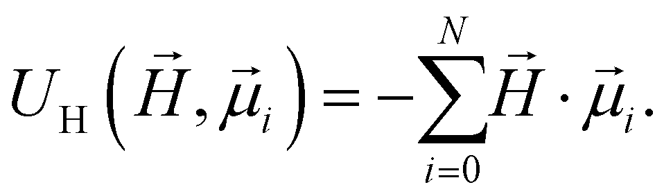 | (4) |
In order to model super-paramagnetic MNPs, one needs to accurately calculate the total field  in each point of the system. The total magnetic field is the sum of
  and the dipolar field
  . The latter field, created by particle j, at position
  is given by:
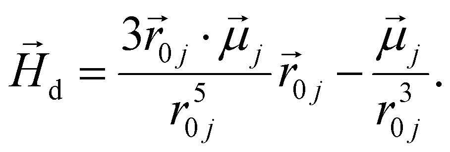 | (5) |
The study of the response of a filament to fields of arbitrary strength requires to one define the dipole moment,  , of an i-th super-paramagnetic particle at a given temperature T, as:
 | (6) |
 denotes the modulus of the maximal magnetic moment of the particle,
  . Here, kB is the Boltzmann constant and L(α) is the Langevin function:
 | (7) |
This approach allows us to consider nonlinear effects, in contrast to work.83 In fact, expression (6) is a generalisation of mean-field approaches, such as the modified mean field approach,93 with the difference that no assumptions were made when calculating  . This approach is also verified by the analytical calculations for super-paramagnetic particle magnetisation.94 The long range magnetic interaction and the Zeeman coupling for super-paramagnetic monomers are accounted for just as they are for ferromagnetic monomers, see eqn (3) and (4), respectively.
2.2. Crosslinking
In this subsection, we present two crosslinking approaches both for ferro- and super-paramagnetic MNPs, in order to realise MFs, distinct in terms of stiffness and inter-particle correlations. These models are shown in Fig. 1. Firstly, we introduce models for MFs with ferro- or super-paramagnetic monomers, that have a very flexible backbone, as only the translational degrees of freedom of monomers are restricted. In these models, depicted in Fig. 1(a), monomers are connected by finitely extendable springs, attached to monomer centres. In Fig. 1(b) we depict a crosslinking model for MFs with ferromagnetic monomers, in which the finitely extendable springs are attached to anchoring sites with permanently fixed positions on the surface of MNPs. Such crosslinking, in comparison to the aforementioned models aimed to represent MFs with a more flexible backbone, introduces extra correlations between the orientations of the magnetic moments of ferromagnetic monomers with the MF backbone, thus leading to a stiffer filament. Finally, in Fig. 1(c), we show a model for MFs with super-paramagnetic monomers, with enhanced backbone rigidity compared to the models aimed to represent MFs with a flexible backbone, realised via explicit three-particle bending potentials (for each consequent three particle set). For a detailed discussion of the models see sections 2.2.1 and 2.2.2 correspondingly.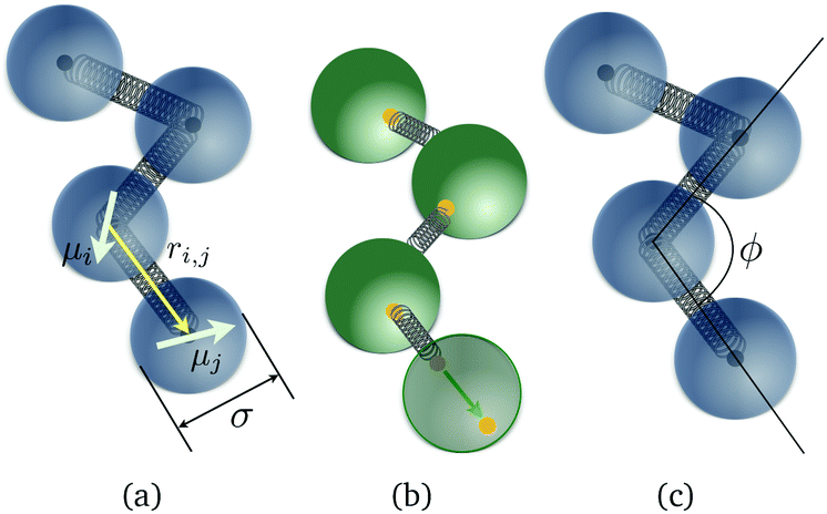 | ||
| Fig. 1 Schematic representations of three different bead-spring models of MFs. Dipole moments are depicted as arrows. The connectivity mechanisms are depicted as springs attached to either filament centres (black dots) or to anchoring sites with permanently fixed positions on the surface of MNPs (yellow dots). (a) Plain crosslinking model; (b) constrained crosslinking model for ferromagnetic MNPs; (c) constrained crosslinking model for super-paramagnetic MNPs. | ||
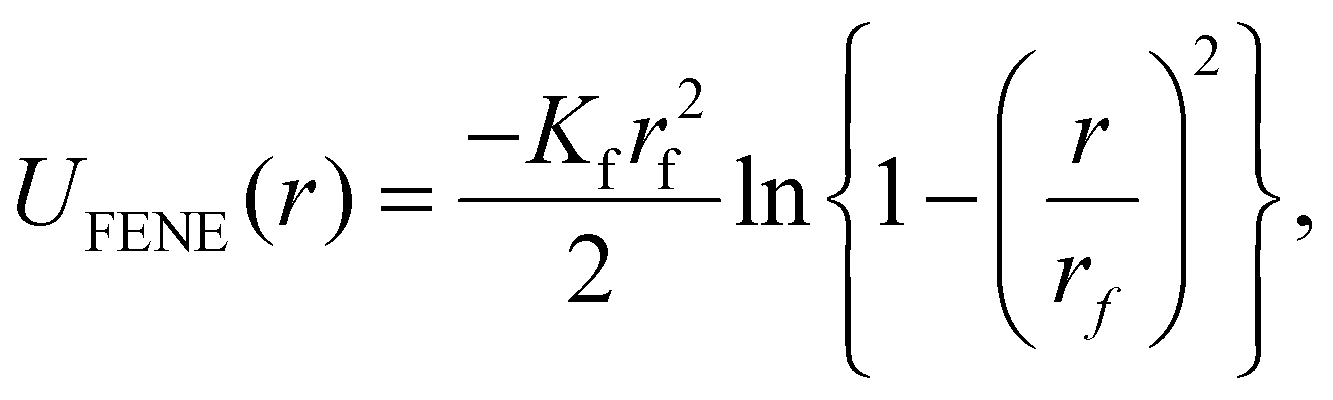 | (8) |
By having all monomers in a line and connected centre-to-centre with FENE bonds, for each two adjacent monomers, we ensure close contact, without introducing any energetic penalty on rotation of the monomers. Therefore, the head-to-tail arrangement of the dipole moments, will be achieved purely trough the cooperative influence of the magnetic dipolar field generated by neighbouring monomers and the external magnetic field (if applied). Throughout the paper we will refer to this modelling approach of crosslinking effects as the plain model, for both ferromagnetic and MFs with super-paramagnetic MNPs.
In case of super-paramagnetic monomers, whose dipole moments are zero in the absence of an applied magnetic field, the anchoring point positions can not be defined. We introduce additional inter-particle correlations between the monomers and stiffness against bending, by adding an isotropic bending pair potential between first-nearest neighbours (see Fig. 1(c)):
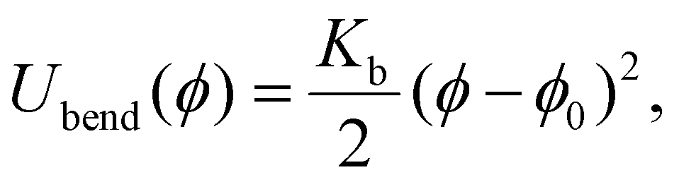 | (9) |
Throughout this paper, we will refer to the two crosslinking models presented in this subsection as constrained model, where it is implicit that for MFs with ferromagnetic MNPs we are referring to the model with anchoring sites, while for MFs with super-paramagnetic MNPs we are talking about direct crosslinking via the FENE potential with an additional bending potential.
2.3. Simulation method
In this subsection we introduce and explain the general formalism and approach we used to computationally investigate magnetic filaments.Using the ESPResSo software package,97 we perform extensive molecular dynamics simulations for each of our crosslinking models, for different values of μmax and dimensionless applied field strength  , where
  is always directed along the z-axis. Due to the relatively modest size of our simulation box and no apparent periodicity in the system, we account for the long range dipole–dipole interactions using direct summation, which calculates energies and forces between dipoles by explicitly summing over all pairs. Simulation of the effects of the background fluid were handled implicitly, via the Langevin thermostat.98
For MFs with ferromagnetic monomers, the dipole moments of each colloid  are initially directed along the filament backbone. Since we are discussing equilibrium properties, our filaments have no preferred orientation with respect to the direction of
  , initially. Moreover, in order to make sure that there is no directional bias introduced by the starting alignment of the MF, initial orientations in our simulations are uniformly distributed on the surface of a sphere. This is particularly important in the low applied magnetic field region.
For super-paramagnetic monomers, the following protocol is implemented. After every integration of the Langevin equations, using forces and torques obtained from the previous integration step, we recalculate the total magnetic field  , and based on the non-linear magnetisation law (6), reset the dipole moments of the monomers in the system.
We run twenty parallel, model specific simulations, each of which for a different H and/or μmax. We firstly make sure that system relaxes into an equilibrium field-free configuration, by running an integration cycle for 108 integration steps. Next we switch on the external magnetic field and start measuring. During the equilibration procedure, we increase the equations of motion integration timestep from 10−8 (which is the numerical precision limit) to 10−2 (which is the timestep we use for the measurement run), and the effective dipole moment of ferromagnetic monomers assigned to each of the monomers from 10−8 up to the value μmax. In case of super-paramagnetic filaments, since there is no H applied during equilibration, there are no dipole moments assigned to the monomers. In order to obtain statistically significant results, we make sure that the snapshots we use for “measuring” are sufficiently far apart from each other to minimise correlations, by performing 1![[thin space (1/6-em)]](https://www.rsc.org/images/entities/char_2009.gif) 050000 integrations, sampling at intervals separated by 3000 integrations each.
050000 integrations, sampling at intervals separated by 3000 integrations each.
2.4. Reduced units and mapping to physical parameters
In this subsection we give a detailed overview of the reduced units used in our simulations, that have been chosen to be representative of possible material choices and experimental conditions. We also provide a mapping of these units to corresponding physical parameters.All distances in our simulations are measured in units of σ (introduced earlier as the monomer diameter). We set the reduced temperature of the Langevin thermostat to be kBT = 1, which determines the energy scale in our simulations. Since we also set the depth of the Leonard–Jones to ε = 1, this means that the energy in our simulations is measured in units of kBT. We consider two values of the reduced saturated magnetic moment  and μ2max = 3, for a range of reduced external magnetic fields H ≤ 6. Given a choice of a particular magnetic nanoparticle, such as using magnetite nanoparticles coated with a thin layer of stabilising agent (i.e. oleic acid coating, 2 nm thick), these values of μ2max correspond to dipole moments of 2.51 × 10⁻¹⁹ and 5.52 × 10⁻¹⁹ A m2, for nanoparticles with core diameters of 10 and 13 nm, respectively. This also means that the maximum of the applied magnetic field range we explored represents moderate fields of only 0.11 T, for MNPs with μ2max = 1 and 0.135 T, for MNPs with μ2max = 3. We chose magnetite as a reference as it is one of the most commonly used magnetic materials in magnetic soft matter. The field in the chosen range spans from initially weak magnetic response to the saturation. The reduced characteristic mass of the monomers is taken m = 1, and given that we are only interested in equilibrium properties of these systems, this value does not affect the results. The factor Kf of the potential given in eqn (8) is set to Kf = 2.5. The maximum extension of the FENE bond rf, is set to rf = 2σ. Experimentally, plain crosslinking could be representative of ferromagnetic and/or super-paramagnetic monomers enclosed into semi-flexible steric cages within a multiple-cage chain structure.99 This would correspond to an effective crosslinking scenario, since the MNPs would not be physically bonded to the cages, rather trapped inside. This crosslinking mechanism, as described, is however, more appropriate for representing crosslinking of super-paramagnetic MNPs. One can interpret the free rotation of the MNP as equivalent to free dipole moment rotation within the colloid. We will elaborate more on why it is a more appropriate model for MFs with super-paramagnetic MNPs later in section 3.
The bending constant Kb of the harmonic angle dependent potential given in eqn (9), is set to Kb = 3.2. Note that these parameters have been chosen so that the end-to-end distance of MFs in our constrained model with ferromagnetic monomers is equal to its counterpart of MFs with super-paramagnetic monomers at H = 0. Experimentally, our constrained models should be representative of ferromagnetic and/or super-paramagnetic MNPs, bonded directly with semi-flexible polymer crosslinkers. This model should also generalise quite well to MFs realised with DNA origami techniques, where orientations of functionalized MNPs are rendered permanent with respect to the filament backbone, by attaching the MNPs to DNA patches inside steric DNA origami cages. The cages subsequently assemble and bond among themselves in to linear conformations, by means of complementary binding vertices.99
3. Results and discussion
We split this part in three subsections, where we, in subsection 3.1, discuss structural properties of MFs, in subsection 3.2, discuss magnetic properties of MFs and in subsection 3.3, present an analytical estimation of the free energy of a plainly crosslinked filament in a strong magnetic field. It should be noted that throughout this paper, results which are plotted with hollow symbols correspond to MFs, whose crosslinking is realised using the plain model, while filled symbols correspond to those, whose crosslinking is realised using constrained models.3.1. Structural properties
In this subsection, we use measures adapted for polymer science,100 such as gyration radius, end-to-end distance, and positional and orientational correlations between monomers, to communicate how the magnetic nature of monomers of MFs, backbone stiffens and inter-particle correlations translate to experimentally measurable quantities, representative of structural properties of filaments.We define the normalised end-to-end distance,  , (the distance between the centres of the first and the N-th monomer) as
Here,  is the position vector of the i-th filament monomer in the lab coordinate frame.
Let us firstly consider results we obtained for the plain crosslinking model. As it can be seen in Fig. 2(a) and (b), for plain crosslinking and μ2max = 1, both  and R2g remain mostly flat as H increases, regardless of the magnetic nature of the monomers. Clearly, in this case magnetic interactions are weak and get dominated by entropy. For μ2max = 3 we can observe an increase in
  and R2g with H. In fact, this increase is particularly pronounced for MFs with super-paramagnetic monomers (here and below plotted with triangles), in the low field region (H < 1). For H > 1, both for
  and R2g, we see largely flat profiles with equal values for MFs with ferro- (here and below plotted with circles) and super-paramagnetic monomers. Observing a higher degree of stretching for MFs with super-paramagnetic monomers can be explained by the local orientation of dipole moments along the field direction. Such a local orientation is supported by dipolar interactions and leads to a head-to-tail alignment of the dipole moments and therefore, stretching of the filament backbone. In the case of MFs with ferromagnetic monomers and μ2max = 3, the dipolar field is not necessarily coaligned with the external magnetic field. Thus, for low-fields, MNPs are distributed in order to optimise dipolar forces. For global reorientation and stretching of a filament with ferromagnetic monomers to take place, higher H fields are needed. For high values of H, the nature of monomers becomes unimportant, and the MFs reach a state when its
  is approximately 20% lower than that of a straight rod.
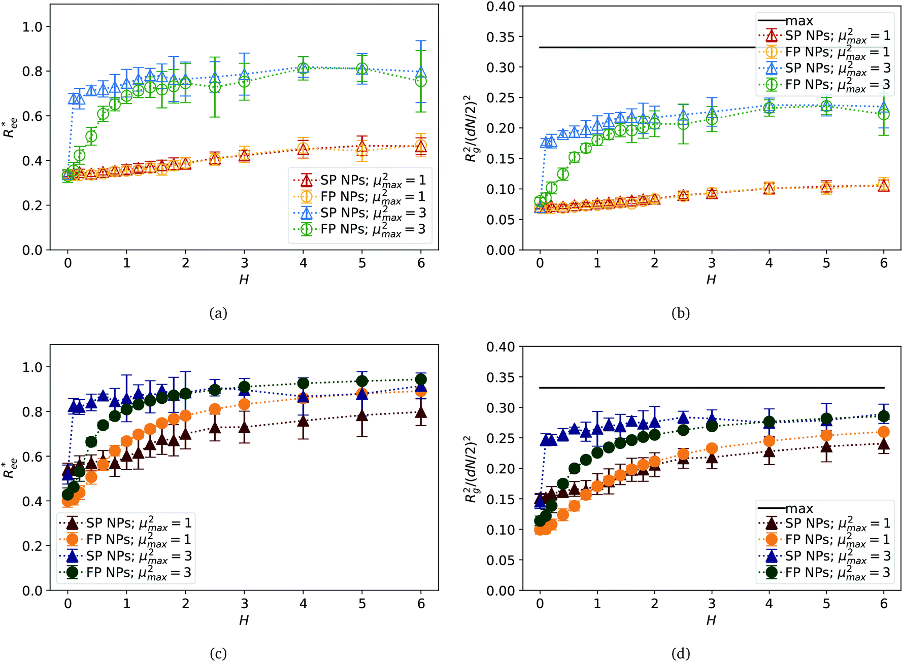 | ||
Fig. 2 Normalised end-to-end distance,  , and the radius of gyration squared, R2g, normalised by (dN/2)2, plotted against the applied external magnetic field H. (a) and (b) MFs with plain crosslinking; (c) and (d) MFs with constrained crosslinking. (a) and (c) , and the radius of gyration squared, R2g, normalised by (dN/2)2, plotted against the applied external magnetic field H. (a) and (b) MFs with plain crosslinking; (c) and (d) MFs with constrained crosslinking. (a) and (c)  ; (b) and (d) R2g. Colour coding for different μ2max is explained in the legends. SP stays for super-paramagnetic monomers; FP – for ferromagnetic ones. The maximum line for ; (b) and (d) R2g. Colour coding for different μ2max is explained in the legends. SP stays for super-paramagnetic monomers; FP – for ferromagnetic ones. The maximum line for  is the fully stretched MF, in units of dN. The maximum line forT> R2g is determined as the normalised R2g for a static rod, fully aligned with is the fully stretched MF, in units of dN. The maximum line forT> R2g is determined as the normalised R2g for a static rod, fully aligned with  . Errorbars are calculated as the standard deviation of the measure in question ( . Errorbars are calculated as the standard deviation of the measure in question ( and R2g, respectively), across 20 independent simulations. and R2g, respectively), across 20 independent simulations. | ||
Once we look at  and R2g for MFs within the constrained crosslinking model, plotted in Fig. 2(c) and (d), we note that the degree of stretching in this case is much higher for all μ2max and monomer types. Looking at Fig. 2(c), we observe substantial differences between
  and R2g for MFs with ferromagnetic and super-paramagnetic monomers, particularly for μ2max = 1. In the low field region, similar to Fig. 2(a) and (b), local stretching of MFs with super-paramagnetic monomers, within the constrained crosslinking model, with μ2max = 1, is still more pronounced than that of their counterparts with ferromagnetic monomers. However, at H ∼ 0.8 and for higher fields, MFs with ferromagnetic monomers are notably more straight. Qualitatively, for μ2max = 3 and constrained crosslinking, the behaviour of
  and R2g is the same as for MFs with plane crosslinking, discussed above: MFs with super-paramagnetic monomers stretch more in low fields than those with ferromagnetic ones. This difference disappears, however, once H grows higher.
The analysis of  and R2g curves reveals an important fact. Within the plain crosslinking model, structural properties of MFs with ferromagnetic monomers become the same as for MFs super-paramagnetic ones.
In summary, based on the analysis of  and R2g curves, if one had to recognise a singular distinguishing factor between MFs, the most appropriate one would not be the magnetic nature of the monomers, but rather the crosslinking approach. Constrained crosslinking not only increases the overall values of
  and R2g, but is necessary in order to be able to obtain a significant difference between field-induced stretching, both for MFs with ferromagnetic and super-paramagnetic monomers. The dipolar strength has a larger impact on
  and R2g in the case of the plain crosslinking: the value of
  for μ2max = 1 is almost two times smaller than that for μ2max = 3 at high H values, whereas the same measure for constrained crosslinking differs at most 15%. Finally, none of the MFs studied here stretches to its full length under the influence of H.
In order to deepen our understanding of the local structure of different MFs, we measured the angle θ between two bonds within a filament with μ2max = 3, separated by a given amount of bonds, l, as shown in Fig. 3(a). Here, if the segments are “touching”, like in the case of segments between monomers 1–2 and 2–3, which are sharing a common monomer 2, l = 0 and the measured angle is addressed as θ0. If the segments are immediately next to each other, but do not share a common monomer, therefore separated by a single bond, as is the case between segments formed by monomers 1–2 and 3–4, l = 1 and correspondingly define an angle θ1. Analogously, θ2 is the angle between segments 1–2 and 4–5, which are separated by two bond lengths. We measure the inter-segment correlations by calculating the cosine of the angle θl, 〈cosθl〉. The averaging is done first over all segments separated by l bonds, then over all snapshots for a particular simulation, and, finally, over all runs.
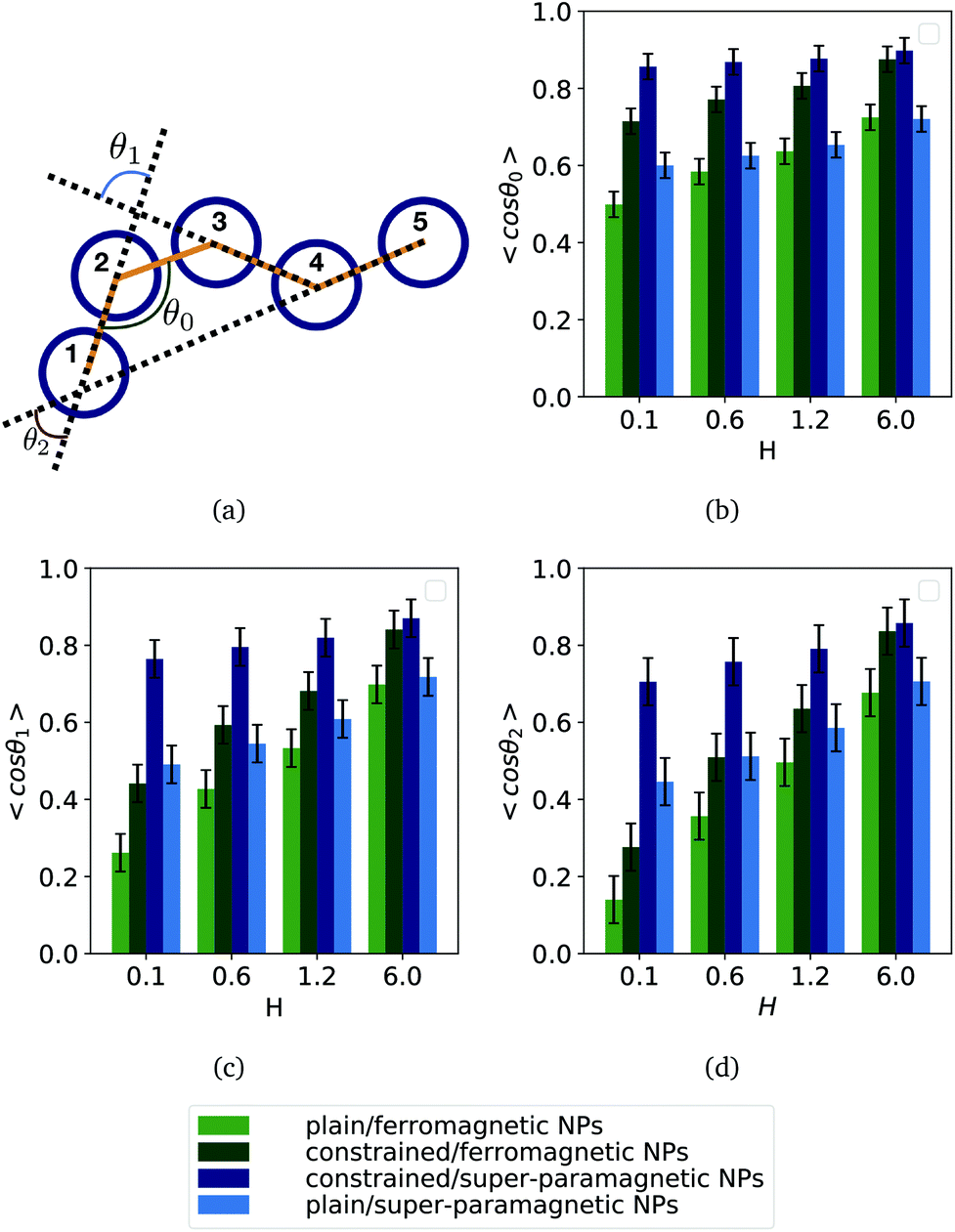 | ||
| Fig. 3 Inter-segment correlations 〈cosθl〉, for four different values of H. (a) 〈cosθ0〉; (b) 〈cosθ1〉; (c) 〈cosθ2〉. Each bar shows a particular combination of magnetic nature of monomers and crosslinking approach, as explained in the legend provided outside the plots. Results are shown for μ2max = 3. Errorbars are calculated as the standard deviation of the measure in question (〈cosθ0〉, 〈cosθ1〉, 〈cosθ2〉, respectively), across 20 independent simulations. | ||
Regardless of crosslinking and magnetic nature of the monomers, the more separated the segments are, the less they are correlated. However, MFs with constrained crosslinking (middle two columns in each bar plot) are more correlated then their plainly crosslinked counterparts and the value of 〈cosθl〉 decays only weakly with increasing l. With growing H inter-segment correlations strengthen.
Comparing the left most and the right most columns in each bar plot for 〈cosθ0〉 shown in Fig. 3(b), one can notice that for weak fields, neighbouring segments of plainly crosslinked MFs with super-paramagnetic monomers (right most columns) are more correlated than in case of ferromagnetic monomers (left most columns). The difference decreases and basically vanishes with growing H. This behaviour explains why radii of gyration and end-to-end distances for plain crosslinking model are found to be higher for super-paramagnetic monomers in low fields (see Fig. 2(a) and (b)), but as H increases, this difference disappears.
Similarly, within the constrained crosslinking model, spatial correlations for MFs with super-paramagnetic monomers (right middle column in each bar plot), coincide with those of MFs with ferromagnetic monomers (left middle columns) only for the highest H value. For lower H, segments in MFs with constrained crosslinking and super-paramagnetic monomers turn out to be more spatially correlated than their counterparts with ferromagnetic monomers. The difference in correlations grows with l. So, MFs with super-paramagnetic monomers and constrained crosslinking exhibit spatial correlations that remain non-negligible further along the filament backbone. This observation explains why in Fig. 2(c) and (d) the values of  and R2g for constrained model are significantly higher for MFs with super-paramagnetic than those with ferromagnetic monomers, especially for H < 2.
3.2. Magnetic response
The main appeal of MFs lies in their responsiveness to external magnetic fields. Investigating different crosslinking scenarios of MFs is interesting because soft matter systems with a microstructure defined via crosslinking have been shown to have much improved responsiveness to external magnetic fields compared to conventional ferrofluids.101 However, the intricate relationship between the magnetic nature of monomers within a filament and crosslinking can result in notably different structural properties and responsiveness of MFs to external magnetic fields. In this subsection, we relate our results on the structural properties of MFs to their response to external magnetic fields and compare it to the magnetic response of non-crosslinked magnetic soft matter systems, such as conventional ferrofluids.93,100In order to understand how spatial correlations between filament segments are related to the overall magnetic response of MFs, we analyse the average value of the normalised projection of filament magnetic moment ![[m with combining macron]](https://www.rsc.org/images/entities/i_char_006d_0304.gif) , on to the direction of
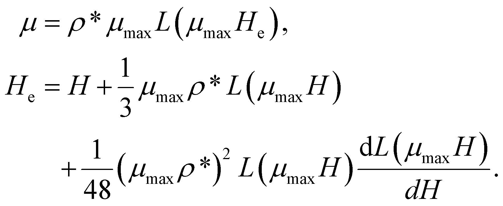
, on to the direction of  , shown in Fig. 4. We normalise curves by the factor Nμmax, where N is the number of MNPs within the filament, and μmax is their maximum dipole moment magnitude. For MFs with non-interacting monomers, corresponding field dependence of normalised would follow the Langevin function of α = μmaxH, given in eqn (7), that is plotted in each subfigure of Fig. 4 with a black, solid line. It is clear that even for μ2max = 1 and plain crosslinking, shown in Fig. 4(a), filament inter-particle correlations manifest themselves, as the actual magnetisation is above the Langevin curve. As we saw above, structural properties of MFs with plain crosslinking and μ2max = 1, are almost independent from H. In order to confirm that the magnetic response of a filament in this case is equivalent to the response that non-crosslinked monomers would have, we consider the magnetisation calculated via modified mean-field theory of the second order (MMFT2).93 MMFT2 is known to describe static magnetic properties of relatively concentrated ferrofluids well, as long as dipolar forces do not lead to cluster formation.102 In the framework of MMFT2, the magnetisation of a monodisperse system has the form:
 | (10) |
 | ||
Fig. 4 Projection of the total MF magnetic moment, normalised by Nμmax, on  versus with dimensionless magnetic field strength H. (a) and (b) MFs with plain crosslinking; (c) and (d) correspond to MFs with constrained crosslinking. In (a) and (c) μ2max = 1; in (b) and (d) μ2max = 3. Each subplot shows four curves, representing results for MFs with either ferro- or super-paramagnetic NPs, Langevin magnetisation law from eqn (7) and MMFT2 from eqn (10) (see the legend). Errorbars are comparable to symbol size and are as such not shown. versus with dimensionless magnetic field strength H. (a) and (b) MFs with plain crosslinking; (c) and (d) correspond to MFs with constrained crosslinking. In (a) and (c) μ2max = 1; in (b) and (d) μ2max = 3. Each subplot shows four curves, representing results for MFs with either ferro- or super-paramagnetic NPs, Langevin magnetisation law from eqn (7) and MMFT2 from eqn (10) (see the legend). Errorbars are comparable to symbol size and are as such not shown. | ||
Here, ρ* is the magnetic particle number density. In order to define ρ* for a filament, we assume that for a given value of H, all MNPs are constrained to a volume V = 4πRg3/3, so ρ* = N/V. The results of eqn (10) are plotted in all subfigures of Fig. 4 with a solid grey line. It can be seen in Fig. 4(a) that for μ2max = 1 and plain crosslinking, MMFT2 describes the magnetisation of MFs well. Clearly, in this case the crosslinking does not affect the magnetic response of the individual monomers. For all other parameter sets however, the crosslinking enhances the magnetisation, especially in the low-H region: simulation data is well above the MMFT2 curve. Looking at the magnetisation of MFs with μ2max = 1 and constrained crosslinking, shown in Fig. 4(c), one can see that the magnetisation is lower for MFs with super-paramagnetic monomers. This fact is in agreement with the field-dependence of  , plotted in Fig. 2(a), showing that MFs with μ2max = 1 and constrained crosslinking can be stretched and magnetised more efficiently if the monomers are ferromagnetic. This changes, however, if μ2max = 3, as it can be seen in Fig. 4(b) and (d). Independently from crosslinking, magnetisation of a filament with super-paramagnetic monomers is higher than for MFs with ferromagnetic ones, as is shown above in Fig. 2. This is rather similar to what we have previously discussed for
  and R2g. Comparing the results from Fig. 4(b) and (d) to correlation plots in Fig. 3, one can notice that for constrained crosslinking models, MFs with super-paramagnetic monomers, that are comparatively more correlated, exhibit higher magnetisation.
Summarising what we have obtained so far, one can say that for μ2max = 1, the highest magnetisation is observed for MFs with ferromagnetic monomers and constrained crosslinking. Furthermore, such MFs stretch more in applied fields and their grows faster with H, than for MFs with super-paramagnetic monomers. The end-to-end distance of such MFs in the region of magnetic saturation is comparable to that of filaments with μ2max = 3. In general, for μ2max = 3, we observe the highest ,  , R2g and spatial correlations in high H fields for MFs with constrained crosslinking and super-paramagnetic monomers. This is in contrast to what we have seen for μ2max = 1. Additionally, for μ2max = 3, plainly crosslinked filaments exhibit lower spatial correlations, which results in lower values of ,
  and R2g for the complete range of the applied fields that we explored. However, looking at the magnetisation of each monomer within a filament, plotted in Fig. 5, one cannot see any significant difference between MFs with μ2max = 3, regardless of the crosslinking model. Empty bars are used to show the magnetisation of a particular monomer in a filament within the plain crosslinking model, whose position along the filament backbone is given on the x-axis; filled bars are used to plot magnetisation for monomers in MFs within the constrained crosslinking model. The colour-coding corresponding to the values of μ2max is analogous to Fig. 2–4. From the top to the bottom of Fig. 5, strength of the applied magnetic field is growing: H = 0.2, 1.4 and 6. The first two columns on the left are plotted for MFs with ferromagnetic monomers, whereas the last two columns depict data for MFs with super-paramagnetic monomers. It is exactly in Fig. 5(e)–(l), where one can notice that even though previously reported values of
  and R2g for MFs with plain crosslinking and μ2max = 3, are lower than their counterparts with constrained crosslinking, empty blue and green bars turn out to be of the same height as filled blue and green bars. This is also a feature that is independent from the position of the monomer. In other words, for relatively strong fields and high values of μ2max, each monomer inside a plainly crosslinked filament, exhibits the same magnetisation as if it was a filament with constrained crosslinking, independently from the magnetic nature of the monomers. At the same time, plainly crosslinked MFs are not as stretched as their counterparts with constrained crosslinking. This can only be the case if the conformations of MFs are drastically different from each other, depending on the crosslinking model.
 | ||
| Fig. 5 Bar-Plot comparison of per-particle magnetisation # of MFs. Each bar corresponds to a colloid within the respective filament. Subplots (a), (b), (e), (f), (i) and (j) depict results for MFs with ferromagnetic MNPs, while subplots (c), (d), (g), (h), (k) and (l) depict results for MFs with super-paramagnetic MNPs. Out of the subplots showing results for MFs with ferromagnetic MNPs, subplots (a), (e) and (i) represent MFs with plain crosslinking, while subplots (b), (e) and (j) represent MFs with constrained crosslinking. Out of the subplots showing results for MFs with super-paramagnetic MNPs, subplots (c), (g) and (k) represent MFs with plain crosslinking, while subplots (d), (h) and (l) represent MFs with constrained crosslinking. Column groups of subplots show filament # results for the same value of H, where subplots (a)–(d) show results for H = 0.2, (e)–(h) show results for H = 1.4 and subplots (i)–(l) show results for H = 6.0. All subplots contain # results for both μ2max = 1 and μ2max = 3 (see subplot legends, respectively). Errorbars are not shown as they are small enough to hardly be legible. | ||
In Fig. 6 we depict the differences between typical conformations of MFs with plain and constrained crosslinking, for two different values of H: in Fig. 6(a)–(d)H = 0.4; in Fig. 6(e)–(h)H = 2. All simulation snapshots were obtained for MFs with μ2max = 3.
 | ||
| Fig. 6 Typical conformations of MFs obtained from simulations for μ2max = 3. (a) and (e) MFs realised with plain crosslinking and super-paramagnetic monomers; (b) and (f) MFs realised with plain crosslinking and ferromagnetic monomers; (c) and (g) MFs realised with constrained crosslinking and super-paramagnetic monomers; (d) and (h) MFs realised with constrained crosslinking and ferromagnetic monomers. | ||
It can be seen that expected additional rigidity manifests itself at low fields, by causing an overall unravelling of MFs. However, at high fields, where one can assume that minimisation of dipolar (eqn (3)) and Zeeman (eqn (5)) energies should necessarily lead to the chain stretching independently from crosslinking model, we instead see bending of plainly crosslinked MFs as shown in Fig. 6(e) and (f).
This kind of bending is visually similar to the behaviour of polymer chains in nematic fields, observed in ref. 103, or the bending of ferromagnetic micron-sized filaments reported in ref. 69. However, none of the two scenarios can be realised in our systems: instead of a quadrupolar nematic field,103 MFs with magnetic nanoparticles experience Zeeman linear coupling and the interaction between monomers is quadratic. As a result, instead of stretching, at high fields, we observe chain bending; instead of dynamic bending found in ref. 69, here, we find equilibrium conformations of plainly crosslinked MFs in a strong static homogeneous, as shown in Fig. 6(e). In order to shed light on the mechanism leading to bending in plainly crosslinked MFs, we put forward a simplified analytical model below.
3.3. Free energy of a plainly crosslinked MF in a strong magnetic field
In this subsection we introduce an idealised theoretical approach that encompasses the competition between entropy gain of a filament through bending and the corresponding energy loss. The model is based on the combination of Flory approach and direct calculations of dipolar interactions in a folded filament.Let us assume that the Zeeman coupling is strong enough, so that all dipoles in a filament consisting of N monomers, are pointing in the same direction, as shown in Fig. 7. We also assume that all MNPs magnetic moments are saturated and  , independently from the magnetic nature of the monomers.
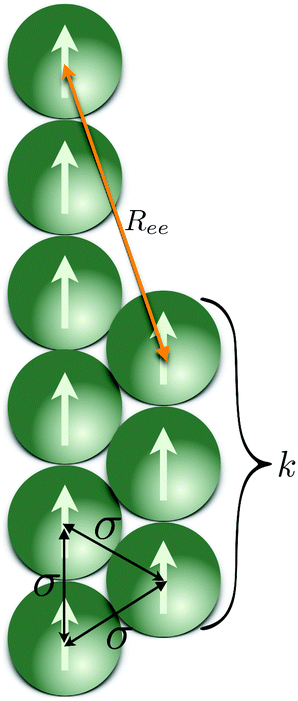 | ||
| Fig. 7 Schematic depiction of a folded MF, where the segments of the folded chain are at σ distance one from another. All dipole moments are aligned with the applied external magnetic field H, and set in magnitude, to the saturation value of their respective magnetisation curves. Length of the shorter segment k, changes as the filament folds further or attempts to unfold completely. | ||
We expect a competition between three contributions to the free energy of a filament: entropy, that favours a non-stretched configuration, Zeeman energy, constant in our assumptions, and dipolar interactions, that favour a head-to-tail orientation of dipoles. The way we deal with dipolar contributions to the free energy, is by splitting them into head-to-tail terms, Uhtt, and diagonal terms, Udia: Udip = Uhtt + Udia. Both terms depend on the folding, characterised in our model by the number of monomers in the shorter arm of the folded filament, k ≤ ⌊N/2⌋, as shown in Fig. 7. In order to simplify the calculations, we assume that the two parts of a folded filament are touching and the separation between all touching monomers is identical, σ. Uhtt and Udia are the sums of pair dipole–dipole interactions  , given by eqn (3), where the distances between monomers do not fluctuate and can be exactly calculated. In the approximation where monomer positions and dipolar orientations are fixed to
  and
and  respectively, we can get rid of the integration in the partition function over coordinates,
  and orientations,
  , using the delta-function property
 | (11) |
Up to the normalisation constant A, this brings us to a rough estimate of Fhtt(kBT) = Uhtt/(kBT):
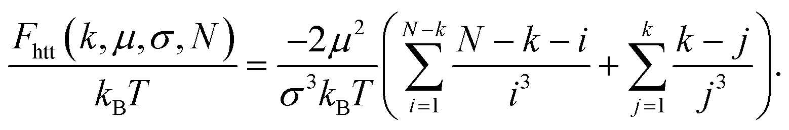 | (12) |
This expression is identical to the chain ground state energy,104 and it was successfully used to estimate chain free energies at low temperature.105 Note, we assume that summation from zero to one, or from one to one provides a zero. Following the same approach and using the same set of approximations as in eqn (11), Udia that contains the sum of all monomer interactions not belonging to the same fold, contributes to the free energy of a filament as Fdia/(kBT) = Udia/(kBT):
 | (13) |
Here, ri in the denominators is
Sum upper limits are defined as
| N1(k,N) = k + (N − 2k − 1 + |N − 2k − 1|)/2 |
| N2(k,N) = N − k − 2. |
The prefactor I(i,k,N) shows how many pairs of monomers are having the same interaction energy. It turns out that the calculation of I(i,k,N) for arbitrary values of k and N is a non-trivial task which results in the following expression:
 | (14) |
In its turn, Kcr depends only on filament length, N:
 | (15) |
Thus, the total dipolar contribution to the free energy of a folded filament can be written as:
 | (16) |
The total Zeeman energy of a filament, UH = −NμH, does not depend on k, so its contribution to the free energy of a filament, after getting rid of the integral and logarithm, simplifies to FH/(kBT) = −UH/(kBT). Finally, following the Flory approximation for a polymer in a good solvent,100 entropic and steric terms, Fent and Fs respectively, of the free energy without magnetic interactions, FNM, can be written as:
 | (17) |
Here, we use end-to-end distance Ree, as a function of k, σ and N, which, by using the cosine theorem, can be obtained in the following form:
Summing all terms up, assuming σ = 1, one can obtain the free energy of an “ideally” folded filament, as a function of k, N and μ:
| F(k, μ, N) = FNM(k, N) + FD(k, μ, N) + FH(μ, N). | (18) |
We want to depict the dependence of FD on k, for different values of N. In order to compare FD values corresponding to a straight chain FD(0, μ, N), to the one a folded chain would have, in Fig. 8(a), we plot the μ-independent dimensionless ratio:
 | (19) |
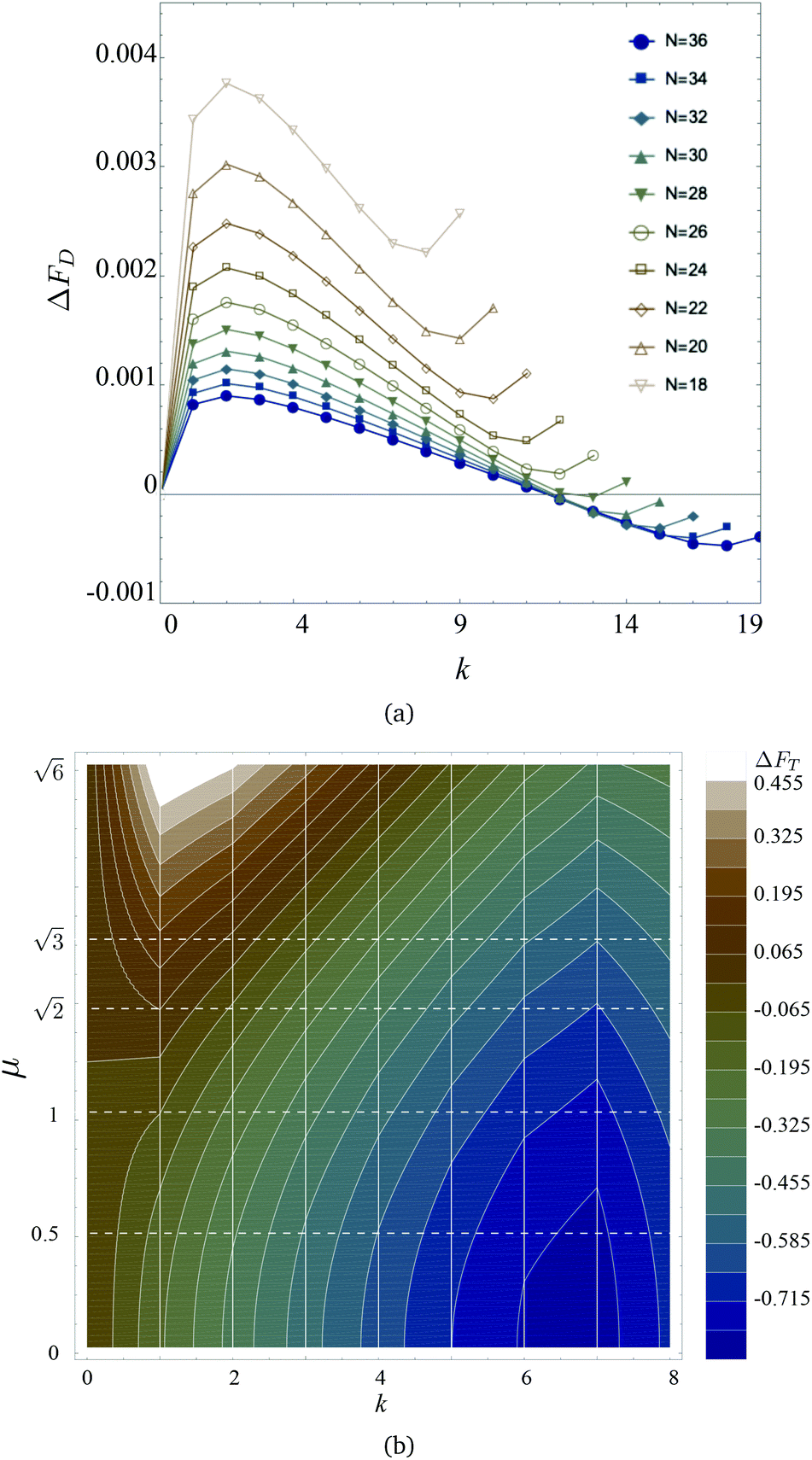 | ||
| Fig. 8 (a) ΔFD from eqn (19)versus k, for different values of MF length N as indicated in the legend. (b) Colour map of ΔFT in simulation units from eqn (20) for different values of k and μ. Contour lines indicate constant values of ΔFT; vertical white lines show k = const cuts, whereas dashed horizontal lines show μ = const sections. Colour coding is provided in the legend on the right. | ||
In this way, all curves collapse to zero at k = 0, and the positive values of ΔFD correspond to the region of parameters where the free energy of a folded chain is higher than that of a straight one. One can see that, for MFs with less than N = 28 monomers, it is magnetically more advantageous to assume a straight conformation. However, along with the minimum at k = 0, the increase of N leads to the development of the secondary minimum at k ∼ N/2 − 1, separated from the first one by a barrier. In fact, for N > 28, we see that ΔFD becomes negative instead for k > 12, revealing that the folded state becomes more advantageous than the straight one.
In this manuscript, however, we observed the folding also for MFs with N = 20: eqn (19) shows that considering only dipolar contribution, such MFs should have remained unfolded. Thus, in Fig. 8(b), we plot the total free energy difference between a straight N = 20-monomer MF and a folded one for different values of μ and k:
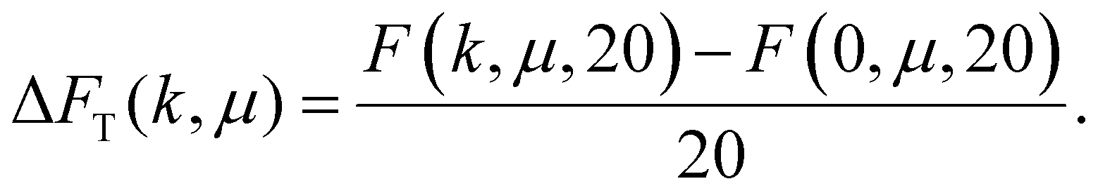 | (20) |
The lighter is the colour in the colour map of ΔFT, the higher is the value of ΔFT(k, μ). In our case, the total free energy difference can be positive, only if the straight conformation is more advantageous than the bent one. Then, ΔFT will be negative if a bent conformation is more advantageous than a straight one. Vertical lines correspond to a given k, contour lines show regions of constant ΔFT. One can see that for small values of μ (bottom part of Fig. 8(b)), the minimum of ΔFT is around k = 6–7, and basically any folding is leading to the decrease of the free energy in comparison to the k = 0 situation. The picture changes dramatically if μ grows: a maximum of ΔFT starts developing at k ∼ 1–2, whereas the minimum corresponding to a folded state shallows, but never disappears. In other words, for a straight MF with plain crosslinking to bend, it needs to overcome a barrier introduced by the dipole–dipole interaction. Once folded, however, it reaches its global minimum of the free energy. Note that if we now compute  , defined in section 3.1, corresponding to the values of k ∼ 6–7 in which ΔFT reaches its minimum, we will obtain
  that is in a good agreement with Fig. 2(a).
To summarise this section, one should underline that bending has not only entropic but also energetic advantages, especially if the number of monomers in the MF is large (N ∼ 30). The length considered in this manuscript, however, corresponds to the case, when bending corresponds to the local energy minimum, but is favoured by entropy at finite temperature.
4. Conclusions
In this study, we develop models that efficiently and accurately encompass the effects of crosslinking in terms of inter-particle correlations and backbone stiffness, and monomer magnetic nature, on the equilibrium properties of MFs. Single domain, ferromagnetic monomers are modelled as point dipolar spheres, whereas the magnetisation of super-paramagnetic monomers is taken into account in an accurate manner, inclusive of non-linear contributions. We compare coarse-grained representations of two distinct crosslinking mechanisms – plain and constrained – for both ferro- and super-paramagnetic monomers. In this work, with plain crosslinking, we address MFs with monomers that can freely rotate. This crosslinking is modelled via centre-to-centre bonds for both ferro- and super-paramagnetic monomers. Other case of crosslinking we address, classified in this work as constrained crosslinking, is the type of bonding, in which additional inter-particle or particle-backbone correlations stiffen the chain. In this work, constrained crosslinking for ferromagnetic monomers results in penalising the rotation of particle magnetisation away from the backbone. For super-paramagnetic monomers, additional inter-particle correlations and stiffness against bending is realised via a three-particle bending potential.Thorough investigation of MFs with different crosslinking and monomer types reveal that the crosslinking mechanism is of major importance, strongly affecting both magnetic and structural properties of MFs. The highest response of MFs to an applied magnetic field, quantified by a change in equilibrium magnetic and/or structural properties, is exhibited by MFs with constrained crosslinking and super-paramagnetic monomers with high susceptibility. Such MFs rapidly magnetise and stretch almost completely, even in a weak applied field. Due to the strict coupling between the orientation of the dipoles and the applied external field, MFs with super-paramagnetic monomers outperform their counterparts with ferromagnetic monomers. In the case of MFs with ferromagnetic monomers, if the monomers are strongly magnetic, in weak fields, dipolar interaction is competing with Zeeman coupling, while in the case of MFs with super-paramagnetic monomers, external field assists the dipolar interactions. On the other hand, even if the monomers are not highly magnetic, constrained crosslinking facilitates equally pronounced stretching in strong fields for MFs with ferro- and super-paramagnetic monomers.
Qualitatively different behaviour was revealed for MFs with plain crosslinking. MFs with ferromagnetic monomers and plain crosslinking are basically indistinguishable from their counterparts with super-paramagnetic monomers in range of applied fields we considered. In low fields, the correlations between super-paramagnetic monomers are enhanced by the alignment of their magnetisation with the external field, while the ferromagnetic monomer magnetisation direction can fluctuate strongly. In high fields, instead, even though each super-paramagnetic monomer in a plainly crosslinked MF is also eagerly magnetised almost to the saturation, it turns out that the interplay between entropy and dipolar interactions prevents such MFs from stretching and leads to bending instead. This bending is observed for MFs with plain crosslinking independently from the magnetic nature of monomers. We propose a simple analytical model that explains the nature of bending and quantifies the influence of dipolar forces and chain length on the equilibrium conformations of plainly crosslinked MFs.
Currently, we are investigating longer MFs, together with their bending dynamics in the presence of an explicit solvent.
Conflicts of interest
There are no conflicts to declare.Acknowledgements
This research has been supported by the Russian Science Foundation Grant No. 19-12-00209. Authors acknowledge support from the Austrian Research Fund (FWF), START-Projekt Y 627-N27. Computer simulations were performed at the Vienna Scientific Cluster (VSC-3).References
- A. C. Balazs, T. Emrick and T. P. Russell, Science, 2006, 314, 1107–1110 CrossRef CAS PubMed.
- J. Hu and S. Liu, Macromolecules, 2010, 43, 8315–8330 CrossRef CAS.
- F. D. Jochum and P. Theato, Chem. Soc. Rev., 2013, 42, 7468–7483 RSC.
- S. Dai, P. Ravi and K. C. Tam, Soft Matter, 2008, 4, 435–449 RSC.
- J. P. Magnusson, A. Khan, G. Pasparakis, A. O. Saeed, W. Wang and C. Alexander, J. Am. Chem. Soc., 2008, 130, 10852–10853 CrossRef CAS PubMed.
- R. V. Ulijn, J. Mater. Chem., 2006, 16, 2217–2225 RSC.
- R. Tietze, J. Zaloga, H. Unterweger, S. Lyer, R. P. Friedrich, C. Janko, M. Pöttler, S. Dürr and C. Alexiou, Biochem. Biophys. Res. Commun., 2015, 468, 463–470 CrossRef CAS PubMed.
- Q. A. Pankhurst, N. T. K. Thanh, S. K. Jones and J. Dobson, J. Phys. D: Appl. Phys., 2009, 42, 224001 CrossRef.
- S. Odenbach, Arch. Appl. Mech., 2016, 86, 269–279 CrossRef.
- W. Scholz, J. Fidler, T. Schrefl, D. Suess, H. Forster and V. Tsiantos, et al. , Comput. Mater. Sci., 2003, 28, 366–383 CrossRef CAS.
- E. Resler and R. Rosensweig, AIAA J., 1964, 2, 1418–1422 CrossRef.
- E. Blums, A. Cebers and M. M. Maiorov, Magnetic Fluids, Walter de Gruyter, 1997 Search PubMed.
- S. Odenbach, Ferrofluids: magnetically controllable fluids and their applications, Springer, 2008, vol. 594 Search PubMed.
- Colloidal Magnetic Fluids, ed. S. Odenbach, Springer-Verlag, Berlin Heidelberg, 2009, vol. 763 Search PubMed.
- M. Zrınyi, D. Szabó and H.-G. Kilian, Polym. Gels Networks, 1998, 6, 441–454 CrossRef.
- R. Weeber, M. Hermes, A. M. Schmidt and C. Holm, J. Phys.: Condens. Matter, 2018, 30, 063002–063002 CrossRef PubMed.
- T. Volkova, V. Böhm, T. Kaufhold, J. Popp, F. Becker, D. Y. Borin, G. Stepanov and K. Zimmermann, J. Magn. Magn. Mater., 2017, 431, 262–265 CrossRef CAS.
- G. Filipcsei, I. Csetneki, A. Szilágyi and M. Zrínyi, Oligomers-Polymer Composites-Molecular Imprinting, Springer, 2007, pp. 137–189 Search PubMed.
- Y. Li, J. Li, W. Li and H. Du, Smart Mater. Struct., 2014, 23, 123001 CrossRef.
- P. A. Sánchez, E. S. Minina, S. S. Kantorovich and E. Y. Kramarenko, Soft Matter, 2019, 15, 175–189 RSC.
- S. Frank and P. C. Lauterbur, Nature, 1993, 363, 334 CrossRef CAS PubMed.
- R. Weeber, S. Kantorovich and C. Holm, Soft Matter, 2012, 8, 9923 RSC.
- R. Dreyfus, J. Baudry, M. L. Roper, M. Fermigier, H. A. Stone and J. Bibette, Nature, 2005, 437, 862–865 CrossRef CAS PubMed.
- J. J. Benkoski, S. E. Bowles, R. L. Jones, J. F. Douglas, J. Pyun and A. Karim, J. Polym. Sci., Part B: Polym. Phys., 2008, 46, 2267–2277 CrossRef CAS.
- E. M. Furst, C. Suzuki, M. Fermigier and A. P. Gast, Langmuir, 1998, 14, 7334–7336 CrossRef CAS.
- E. M. Furst and A. P. Gast, Phys. Rev. Lett., 1999, 82, 4130–4133 CrossRef CAS.
- C. Goubault, P. Jop, M. Fermigier, J. Baudry, E. Bertrand and J. Bibette, Phys. Rev. Lett., 2003, 91, 260802 CrossRef CAS PubMed.
- L. Cohen-Tannoudji, E. Bertrand, L. Bressy, C. Goubault, J. Baudry, J. Klein, J. F. Joanny and J. Bibette, Phys. Rev.Lett., 2005, 94, 038301 CrossRef PubMed.
- H. Singh, P. E. Laibinis and T. A. Hatton, Langmuir, 2005, 21, 11500–11509 CrossRef CAS PubMed.
- H. Singh, P. E. Laibinis and T. A. Hatton, Nano Lett., 2005, 5, 2149–2154 CrossRef CAS PubMed.
- F. Martínez-Pedrero, M. Tirado-Miranda, A. Schmitt and J. Callejas-Fernández, Phys. Rev. E, 2007, 76, 011405 CrossRef PubMed.
- B. A. Evans, A. R. Shields, R. L. Carroll, S. Washburn, M. R. Falvo and R. Superfine, Nano Lett., 2007, 7, 1428–1434 CrossRef CAS PubMed.
- Z. Zhou, G. Liu and D. Han, ACS Nano, 2009, 3, 165–172 CrossRef CAS PubMed.
- J. J. Benkoski, J. L. Breidenich, O. M. Uy, A. T. Hayes, R. M. Deacon, H. B. Land, J. M. Spicer, P. Y. Keng and J. Pyun, J. Mater. Chem., 2011, 21, 7314–7325 RSC.
- H. Wang, Y. Yu, Y. Sun and Q. Chen, Nano, 2011, 06, 1–17 CrossRef.
- D. Sarkar and M. Mandal, J. Phys. Chem. C, 2012, 116, 3227–3234 CrossRef CAS.
- J. L. Breidenich, M. C. Wei, G. V. Clatterbaugh, J. J. Benkoski, P. Y. Keng and J. Pyun, Soft Matter, 2012, 8, 5334–5341 RSC.
- E. Busseron, Y. Ruff, E. Moulin and N. Giuseppone, Nanoscale, 2013, 5, 7098–7140 RSC.
- J. Byrom, P. Han, M. Savory and S. L. Biswal, Langmuir, 2014, 30, 9045–9052 CrossRef CAS PubMed.
- L. J. Hill and J. Pyun, ACS Appl. Mater. Interfaces, 2014, 6, 6022–6032 CrossRef CAS PubMed.
- M. B. Bannwarth, S. Utech, S. Ebert, D. A. Weitz, D. Crespy and K. Landfester, ACS Nano, 2015, 9, 2720–2728 CrossRef CAS PubMed.
- A. Hosseinifar, M. Shariaty-Niassar, S. Seyyed Ebrahimi and M. Moshref-Javadi, Langmuir, 2017, 33, 14728–14737 CrossRef CAS PubMed.
- Y. Xiong, Q. Chen, N. Tao, J. Ye, Y. Tang, J. Feng and X. Gu, Nanotechnology, 2007, 18, 345301 CrossRef.
- Z. Zhou, G. Liu and D. Han, ACS Nano, 2008, 3, 165–172 CrossRef PubMed.
- F. Zhang and C.-C. Wang, J. Phys. Chem. C, 2008, 112, 15151–15156 CrossRef CAS.
- M. Ma, Q. Zhang, J. Dou, H. Zhang, D. Yin, W. Geng and Y. Zhou, J. Colloid Interface Sci., 2012, 374, 339–344 CrossRef CAS PubMed.
- S. H. Xu, G. T. Fei, H. M. Ouyang, Y. Zhang, P. C. Huo and L. De Zhang, J. Mater. Chem. C, 2015, 3, 2072–2079 RSC.
- X. Wen, L. Gu and A. M. Bittner, Z. Phys. Chem., 2018, 232, 1631–1646 CAS.
- B. Bharti, A.-L. Fameau, M. Rubinstein and O. D. Velev, Nat. Mater., 2015, 14, 1104–1109 CrossRef CAS PubMed.
- M. Bennet, L. Bertinetti, R. K. Neely, A. Schertel, A. Körnig, C. Flors, F. D. Müller, D. Schüler, S. Klumpp and D. Faivre, Faraday Discuss., 2015, 181, 71–83 RSC.
- É. Bereczk-Tompa, F. Vonderviszt, B. Horváth, I. Szalai and M. Pósfai, Nanoscale, 2017, 9, 15062–15069 RSC.
- S. Kralj and D. Makovec, ACS Nano, 2015, 9, 9700–9707 CrossRef CAS PubMed.
- M. M. Maye, D. Nykypanchuk, M. Cuisinier, D. van der Lelie and O. Gang, Nat. Mater., 2009, 8, 388–391 CrossRef CAS PubMed.
- D. Sun, A. L. Stadler, M. Gurevich, E. Palma, E. Stach, D. van der Lelie and O. Gang, Nanoscale, 2012, 4, 6722 RSC.
- D. Sun and O. Gang, Langmuir, 2013, 29, 7038–7046 CrossRef CAS PubMed.
- Y. Zhang, F. Lu, K. G. Yager, D. van der Lelie and O. Gang, Nat. Nanotechnol., 2013, 8, 865–872 CrossRef CAS PubMed.
- S. Srivastava, D. Nykypanchuk, M. Fukuto, J. D. Halverson, A. V. Tkachenko, K. G. Yager and O. Gang, J. Am. Chem. Soc., 2014, 136, 8323–8332 CrossRef CAS PubMed.
- Y. Tian, T. Wang, W. Liu, H. L. Xin, H. Li, Y. Ke, W. M. Shih and O. Gang, Nat. Nanotechnol., 2015, 10, 637–644 CrossRef CAS PubMed.
- W. Liu, J. Halverson, Y. Tian, A. V. Tkachenko and O. Gang, Nat. Chem., 2016, 8, 867 CrossRef CAS PubMed.
- H. Wang, Y. Yu, Y. Sun and Q. Chen, Nano, 2011, 06, 1–17 CrossRef.
- H. Wang, A. Mararenko, G. Cao, Z. Gai, K. Hong, P. Banerjee and S. Zhou, ACS Appl. Mater. Interfaces, 2014, 6, 15309–15317 CrossRef CAS.
- A. Cebers and K. Erglis, Adv. Funct. Mater., 2016, 26, 3783–3795 CrossRef CAS.
- G. Cai, S. Wang, L. Zheng and J. Lin, Micromachines, 2018, 9, 624 CrossRef.
- R. Dreyfus, J. Baudry, M. L. Roper, M. Fermigier, H. A. Stone and J. Bibette, Nature, 2005, 437, 862–865 CrossRef CAS PubMed.
- K. Ērglis, L. Alberte and A. Cēbers, Magnetohydrodynamics, 2008, 44, 223–236 CrossRef.
- D. Fayol, G. Frasca, C. Le Visage, F. Gazeau, N. Luciani and C. Wilhelm, Adv. Mater., 2013, 25, 2611–2616 CrossRef CAS PubMed.
- F. Gerbal, Y. Wang, F. Lyonnet, J.-C. Bacri, T. Hocquet and M. Devaud, Proc. Natl. Acad. Sci. U. S. A., 2015, 112, 7135–7140 CrossRef CAS PubMed.
- B. Evans, A. Shields, R. L. Carroll, S. Washburn, M. Falvo and R. Superfine, Nano Lett., 2007, 7, 1428–1434 CrossRef CAS PubMed.
- K. Ērglis, R. Livanovičs and A. Cēbers, J. Magn. Magn. Mater., 2011, 323, 1278–1282 CrossRef.
- A. Cēbers, J. Phys.: Condens. Matter, 2003, 15, S1335 CrossRef.
- V. P. Shcherbakov and M. Winklhofer, Phys. Rev. E, 2004, 70, 061803 CrossRef PubMed.
- A. Cēbers and I. Javaitis, Phys. Rev. E, 2004, 69, 021404 CrossRef PubMed.
- A. Cēbers, Curr. Opin. Colloid Interface Sci., 2005, 10, 167–175 CrossRef.
- M. Belovs and A. Cēbers, Phys. Rev. E, 2006, 73, 051503 CrossRef CAS PubMed.
- A. Cēbers and T. Cīrulis, Phys. Rev. E, 2007, 76, 031504 CrossRef PubMed.
- K. Ērglis, D. Zhulenkovs, A. Sharipo and A. Cēbers, J. Phys.: Condens. Matter, 2008, 20, 204107 CrossRef.
- A. A. Kuznetsov, J. Magn. Magn. Mater., 2019, 470, 28–32 CrossRef CAS.
- E. Gauger and H. Stark, Phys. Rev. E, 2006, 74, 021907 CrossRef PubMed.
- M. Roper, R. Dreyfus, J. Baudry, M. Fermigier, J. Bibette and H. A. Stone, J. Fluid Mech., 2006, 554, 167–190 CrossRef.
- M. Roper, R. Dreyfus, J. Baudry, M. Fermigier, J. Bibette and H. A. Stone, Proc. R. Soc. London, Ser. A, 2008, 464, 877–904 CrossRef.
- S. Huang, G. Pessot, P. Cremer, R. Weeber, C. Holm, J. Nowak, S. Odenbach, A. M. Menzel and G. K. Auernhammer, Soft Matter, 2016, 12, 228–237 RSC.
- J. Zhao, D. Du and S. L. Biswal, Phys. Rev. E, 2018, 98, 012602 CrossRef CAS PubMed.
- J. Wei, F. Song and J. Dobnikar, Langmuir, 2016, 32, 9321–9328 CrossRef CAS PubMed.
- S. Kuei, B. Garza and S. L. Biswal, Phys. Rev. Fluids, 2017, 2, 104102 CrossRef.
- J. M. Dempster, P. Vázquez-Montejo and M. O. de la Cruz, Phys. Rev. E, 2017, 95, 052606 CrossRef.
- P. Vázquez-Montejo, J. M. Dempster and M. O. de la Cruz, Phys. Rev. Mater., 2017, 1, 064402 CrossRef.
- O. Philippova, A. Barabanova, V. Molchanov and A. Khokhlov, Eur. Polym. J., 2011, 47, 542–559 CrossRef CAS.
- O. S. Pak, W. Gao, J. Wang and E. Lauga, Soft Matter, 2011, 7, 8169–8181 RSC.
- P. A. Sánchez, E. S. Pyanzina, E. V. Novak, J. J. Cerdà, T. Sintes and S. S. Kantorovich, Macromolecules, 2015, 48, 7658–7669 CrossRef PubMed.
- S. L. Biswal and A. P. Gast, Anal. Chem., 2004, 76, 6448–6455 CrossRef CAS PubMed.
- T. Yang, T. O. Tasci, K. B. Neeves, N. Wu and D. W. Marr, Langmuir, 2017, 33, 5932–5937 CrossRef CAS PubMed.
- J. D. Weeks, D. Chandler and H. C. Andersen, J. Chem. Phys., 1971, 54, 5237–5247 CrossRef CAS.
- A. O. Ivanov and O. B. Kuznetsova, Phys. Rev. E, 2001, 64, 041405 CrossRef CAS PubMed.
- E. A. Elfimova, A. O. Ivanov and P. J. Camp, Nanoscale, 2019, 11, 21834–21846 RSC.
- P. A. Sánchez, J. J. Cerdà, T. M. Sintes, A. O. Ivanov and S. S. Kantorovich, Soft Matter, 2015, 11, 2963–2972 RSC.
- P. A. Sánchez, E. S. Pyanzina, E. V. Novak, J. J. Cerdà, T. Sintes and S. S. Kantorovich, Faraday Discuss., 2016, 186, 241–263 RSC.
- A. Arnold, O. Lenz, S. Kesselheim, R. Weeber, F. Fahrenberger, D. Roehm, P. Košovan and C. Holm, Meshfree Methods for Partial Differential Equations VI, Springer, Berlin, Heidelberg, 2013, vol. 89, pp. 1–23 Search PubMed.
- M. P. Allen and D. J. Tildesley, Computer simulation of liquids, Oxford University Press, 2017 Search PubMed.
- Y. Tian, Y. Zhang, T. Wang, H. L. Xin, H. Li and O. Gang, Nat. Mater., 2016, 15, 654–661 CrossRef CAS PubMed.
- M. Rubinstein and R. H. Colby, Polymer Physics, Oxford University Press, 2003 Search PubMed.
- P. A. Sánchez, J. J. Cerdà, T. Sintes and C. Holm, J. Chem. Phys., 2013, 139, 044904 CrossRef PubMed.
- V. A. Ivanov and J. A. Martemyanova, Macromol. Symp., 2007, 252, 12–23 CrossRef CAS.
- A. Tkachenko and Y. Rabin, Macromolecules, 1995, 28, 8646–8656 CrossRef CAS.
- T. A. Prokopieva, V. A. Danilov, S. S. Kantorovich and C. Holm, Phys. Rev. E, 2009, 80, 031404 CrossRef PubMed.
- S. Kantorovich, A. O. Ivanov, L. Rovigatti, J. M. Tavares and F. Sciortino, Phys. Rev. Lett., 2013, 110, 148306 CrossRef PubMed.
| This journal is © The Royal Society of Chemistry 2020 |