
Germanium-based high-performance dual-ion batteries†
Jing
Zhou‡
 a,
Yan
Zhou‡
a,
Xu
Zhang
b,
Liwei
Cheng
c,
Mengmeng
Qian
c,
Wei
Wei
*b and
Hua
Wang
*c
a,
Yan
Zhou‡
a,
Xu
Zhang
b,
Liwei
Cheng
c,
Mengmeng
Qian
c,
Wei
Wei
*b and
Hua
Wang
*c
aSchool of Chemistry Engineering, Northeast Electric Power University, Jilin 132012, China
bSchool of Chemistry and Chemical Engineering, Henan Key Laboratory of Biomolecular Recognition and Sensing, Henan D&A Engineering Center of Advanced Battery Materials, Shangqiu Normal University, Shangqiu 476000, China. E-mail: weiweizzuli@163.com
cSchool of Chemistry, Beijing Advanced Innovation Center for Biomedical Engineering, Beihang University, Beijing 100191, China. E-mail: wanghua8651@buaa.edu.cn
First published on 29th November 2019
Abstract
Recently, dual-ion batteries (DIBs) have received immense attention owing to their high operating voltage and low cost, and further studies on the enhancement of their energy densities and cyclabilities are being intensively pursued. Herein, a novel Ge-based DIB has been developed for the first time by using a rationally designed nanocomposite of Ge particles embedded in one-dimensional carbon nanofibers (Ge/CNFs) as an anode. The resulting battery shows a high discharge capacity of 281 mA h g−1 at a discharge current of 0.25 A g−1 and a superb rate capability of 94 mA h g−1 at a discharge current of 2.5 A g−1, which greatly surpasses those of most of the reported DIBs. These remarkable properties can be ascribed to the fact that the uniform one-dimensional nanostructure facilitates the improvement of lithium-ion diffusion within the hybrids, and the carbon matrix effectively alleviates the volume expansion of Ge during the cycling process and simultaneously enhances the electrical conductivity of the hybrids. The charge storage mechanism of Ge/CNFs is found to be Ge alloying with Li, accompanied by a phase transformation process from crystalline Ge to amorphous LixGe alloys. This work paves the way for the rational utilization of Ge-based materials in new-generation high-performance DIBs.
Nowadays, lithium-ion batteries (LIBs) are widely used in consumer electronics owing to their high energy density and long cycle life.1–4 Nonetheless, the limited and unevenly distributed global lithium resources may hinder their development prospects in the future battery market.5–8 In this context, it is desirable to develop new-generation rechargeable battery systems with cost efficiency, good safety and outstanding electrochemical performance. Dual-ion batteries (DIBs), in which carbonaceous materials are typically used as both anodes and cathodes, have received great attention due to their advantages of high operating voltage (mainly above 4.5 V) and low cost.9–13 In contrast to the conventional “rocking chair” LIBs, this novel battery system realizes cations and anions in the electrolyte simultaneously intercalating/deintercalating into/from anode materials and cathode materials, respectively, during the charging/discharging process.14–17 Nevertheless, carbonaceous materials as anodes often suffer from an intrinsically low theoretical capacity (∼372 mA h g−1). Thus, it is critically essential to develop alternative anode materials for DIBs with higher reversible capacity.18–20
Alloy-type electrode materials have been regarded as suitable anode materials for DIBs due to their high theoretical capacity and relatively low cost.21 Among them, Ge is a promising anode material owing to its ultrahigh volumetric and gravimetric capacities (7360 mA h cm−3 and 1626 mA h g−1), superb lithium-ion diffusivity (400 times faster than that in Si) and higher electrical conductivity (104 times) compared with Si.22,23 In spite of these merits, it is the tremendous volume change of about 370% of Ge after being fully lithiated which causes the pulverisation of active materials and fast capacity fading, limiting its practical applications.24,25 To address the aforementioned drawback, dispersing the nanosized Ge into a carbon matrix has been an ideal strategy. Carbon acts as a buffer matrix alleviating the considerable volume change of Ge during the cycling process and simultaneously enhances the electrical conductivity of the hybrid, which are both beneficial for the electrochemical performance.26–29 Thus, understanding the charge storage mechanism and developing a rationally designed nanostructure to optimize the electrochemical performance of Ge-based DIBs are relevant and urgent.
Herein, we report a Ge-based DIB for the first time. The nanocomposite of Ge nanoparticles embedded in one-dimensional carbon nanofibers (Ge/CNFs) is employed as both a current collector and an anode material. Owing to the optimized nanostructure of the as-prepared Ge/CNF anode, it shows exceptionally high reversible capacity, long cycle life and excellent rate capability for DIBs. Our work demonstrates a great potential of Ge-based materials as anodes for DIBs, and this design strategy of the electrodes can be extended to other alloy-based anode materials for DIBs.
The Ge/CNFs were prepared via a combination of a facile electrospinning technique and a subsequent thermal treatment. Scanning electron microscopy (SEM) and transmission electron microscopy (TEM) images (Fig. 1a and b) reveal the homogeneous one-dimensional nanostructure of the as-prepared Ge/CNFs with an average diameter of ∼200 nm. Moreover, the average diameter of pure CNFs is slightly larger (∼220 nm) than that of Ge/CNFs. The corresponding selected area electron diffraction (SAED) pattern (inset in Fig. 1b) can be indexed to the diffractions of the (111), (220) and (422) planes of Ge.30 Energy-dispersive spectroscopy (EDS) mapping (Fig. 1c) demonstrates the homogeneous spatial distribution of Ge, C and N elements in the Ge/CNFs and the well-embedded Ge nanoparticles in the carbon matrix. All the distinct diffraction peaks in the X-ray diffraction (XRD) pattern of the Ge/CNFs (Fig. 1d) match well with the diamond cubic phase of Ge (JCPDS no. 04-0545). In addition, a weak and broad peak located at around 25° is ascribed to the amorphous carbon matrix. Furthermore, the Raman spectra of the Ge/CNFs are shown in Fig. 1e; the peak at ∼298 cm−1 can be assigned to the crystalline Ge and two other sharp peaks at 1346 cm−1 and 1588 cm−1 correspond to the D band and G band of the carbon matrix.31,32 The XRD results together with Raman results confirm the presence of Ge and carbon in the Ge/CNFs. The surface chemistry and element bonding configurations of the Ge/CNFs are examined by X-ray photoelectron spectroscopy (XPS) measurements. The high-resolution XPS spectrum of C 1s (Fig. 1f) comprises a typical C–C bond at 284.6 eV and four fitted peaks at 284.1, 285.4, 286.4 and 287.2 eV corresponding to the C–Ge, C–N, C–O and C![[double bond, length as m-dash]](https://www.rsc.org/images/entities/char_e001.gif) O bonds, respectively.33,34 The N 1s spectrum (Fig. 1g) contains two peaks at 396.8 eV (Ge–N) and 398.7 eV (pyridinic N), and the Ge–N bonds formed between Ge nanoparticles and CNFs are beneficial for improving the electrochemical performance.35 The Ge 3d spectrum (Fig. 1h) can be deconvoluted into four peaks at 29.6, 30.6, 31.5 and 32.6 eV indexing to the Ge–Ge, Ge–C, Ge–N, and Ge–O bonds, respectively.36,37 The Ge content in the Ge/CNFs is confirmed by thermogravimetric analysis (TGA) (Fig. 1i). As the temperature increased up to 650 °C, CNFs completely turned into gases, and Ge was first oxidized to GeO and then to the final product GeO2.38 Based on the final weight of GeO2, the Ge content in Ge/CNFs was calculated to be about 39.6 wt%. The high Ge content well embedded in the carbon matrix implies that the as-prepared Ge/CNFs might be a promising anode material for DIBs.
O bonds, respectively.33,34 The N 1s spectrum (Fig. 1g) contains two peaks at 396.8 eV (Ge–N) and 398.7 eV (pyridinic N), and the Ge–N bonds formed between Ge nanoparticles and CNFs are beneficial for improving the electrochemical performance.35 The Ge 3d spectrum (Fig. 1h) can be deconvoluted into four peaks at 29.6, 30.6, 31.5 and 32.6 eV indexing to the Ge–Ge, Ge–C, Ge–N, and Ge–O bonds, respectively.36,37 The Ge content in the Ge/CNFs is confirmed by thermogravimetric analysis (TGA) (Fig. 1i). As the temperature increased up to 650 °C, CNFs completely turned into gases, and Ge was first oxidized to GeO and then to the final product GeO2.38 Based on the final weight of GeO2, the Ge content in Ge/CNFs was calculated to be about 39.6 wt%. The high Ge content well embedded in the carbon matrix implies that the as-prepared Ge/CNFs might be a promising anode material for DIBs.
 | ||
| Fig. 1 Structural characterization of the Ge/CNFs. (a) Typical SEM image. (b) TEM image and SAED pattern (inset). (c) HAADF-STEM image of a single Ge/CNF and the corresponding elemental mapping of Ge, C and N, respectively. (d) XRD patterns and (e) Raman spectra of the Ge/CNFs and CNFs. High-resolution XPS spectra of the Ge/CNFs with deconvolution: (f) C 1s, (g) N 1s and (h) Ge 3d. (i) TGA curves of the Ge/CNFs and CNFs under an air atmosphere. | ||
To prove this concept, the lithium-ion storage performance of the Ge/CNFs was first evaluated by using Li–Ge/CNF half-cells. Cyclic voltammetry (CV) measurement was conducted to investigate the Ge–Li alloying/de-alloying process (Fig. 2a). The obvious difference between the curves of the first cycle and the subsequent cycles may be due to the formation of stable solid electrolyte interphase (SEI) layers.39,40 In the following four cycles, several reduction peaks are detected at 0.10 V, 0.33 V and 0.47 V, corresponding to the multistep formation of different LixGe (from Li2.25Ge to Li4.4Ge) alloys during the discharging process, and the oxidation peak located at around 0.61 V is related to the de-alloying reaction of the LixGe alloys.41–43 After the 2nd cycle, these curves overlapped, signifying the superior reversibility and stability of the Ge/CNFs.
 | ||
| Fig. 2 Electrochemical performance of the Li–Ge/CNF half-cells. (a) CV curves of the Ge/CNFs at a scan rate of 0.2 mV s−1 in a voltage window of 0.01–1.5 V. (b) Charge/discharge profiles of the Ge/CNFs for various cycles at 1 A g−1. (c) Cycling stability of the Ge/CNFs and CNFs at 1 A g−1. (d) Rate capability of the Ge/CNFs and CNFs at various current densities. (e) The Nyquist plots of the Ge/CNFs, CNFs and bulk Ge, with the inset image showing the equivalent circuit. Variation trend of the EIS fitting result: (f) Re, (g) Rsei and (h) Rct. (i) Lithium-ion diffusion coefficients of the Ge/CNFs, CNFs and bulk Ge after 5 cycles. | ||
The Ge/CNF anode shows an initial discharge capacity of 2614 mA h g−1 at a current density of 1 A g−1 (Fig. 2b and c), which is obviously higher than the theoretical capacity of Ge due to the formation of SEI layers on the surface of electrodes and decomposition of the electrolyte.22 After 50 cycles, the Ge/CNFs can still show a reversible specific capacity of 1088 mA h g−1 with nearly 100% coulombic efficiency, which significantly surpasses the 254 mA h g−1 of pure CNFs. The average discharge capacities of 1330, 1232, 1123, 1014, 737 and 425 mA h g−1 were achieved at the different current densities of 0.2, 0.5, 1, 2, 5, and 10 A g−1, respectively, which were evidently higher than those of CNFs. When the current density was abruptly switched back to 0.2 A g−1, the discharge capacity was restored to 1299 mA h g−1 (Fig. 2d), demonstrating the outstanding stability and robustness of the Ge/CNFs. Owing to the pulverization of active materials induced by the well-known volume changes after being fully lithiated, bare Ge can only show a discharge capacity of less than 10 mA h g−1 at different current densities (Fig. S2†), which further confirms that the carbon matrix can maintain the structural stability of the hybrid during cycling. Fig. 2e shows the comparison of the results of electrochemical impedance spectroscopy (EIS) of the Ge/CNFs, CNFs and bulk Ge for the initial five cycles, with the inset showing the corresponding equivalent circuits. Re showed the ohmic resistance of the cell from the electrodes, electrolyte and separator. The semicircle at high frequencies is indexed to the resistance (Rsei) and capacitance (Csei) of SEI layers. The second semicircle at mid frequencies is attributed to the charge-transfer resistance (Rct) and relative double layer capacitance (Cdl). Warburg impedance (Wb) is ascribed to the lithium-ion diffusion resistance between the active materials and electrolyte, which is usually indicated by a straight sloping line at low frequencies.44,45 As shown in Fig. 2f–h, the estimated Re value of the Ge/CNFs and CNFs is obviously lower than that of bulk Ge, which is attributed to the binder-free electrodes and carbon matrix enhancing the electrical conductivity. The Rsei and Rct values of bulk Ge increase dramatically during cycling, suggesting the poor structural stability and sluggish diffusion kinetics. Notably, the Rsei values of the Ge/CNFs and CNFs are smaller than those of bulk Ge and the Rct values decreased with the cycling number, indicating the improved charge transport properties of the Ge/CNFs due to the optimized one-dimensional nanostructure and carbon matrix enhancing the structural stability of the Ge/CNFs.39,46 On the basis of the fitted data of EIS, the Li+-ion diffusion coefficients (DLi+) within the bulk Ge and Ge/CNFs were calculated to be 5.1 × 10⁻¹⁴ and 2.4 × 10⁻¹² cm2 s−1 (Fig. 2i). The detailed calculation process is shown in the ESI.† The enhanced lithium-ion diffusion coefficient in the Ge/CNFs may be attributed to the one-dimensional carbon matrix as a conducting medium, which is beneficial for improving the rate performance.47,48
Moreover, the electrochemical performance of a graphite cathode was also investigated. A typical CV curve (Fig. S3a†) of graphite shows four pairs of redox peaks corresponding to the PF6− ions intercalating/deintercalating into/from graphite.49,50 The graphite cathode shows an initial discharge capacity of about 67 mA h g−1 at a current density of 100 mA g−1 with an initial coulombic efficiency of ∼71%, and remains at 45 mA h g−1 after 100 cycles (Fig. S3b†). Fig. S3c† shows the rate performance of the graphite cathode at various current densities of 100–1000 mA g−1, yielding discharge capacities of 52–18 mA h g−1, respectively. In view of the excellent lithium-ion storage performance of the Ge/CNFs, a novel Ge/CNF–G DIB was assembled by utilizing the Ge/CNFs as anode materials and graphite as a cathode material (Fig. 3a). The CV curves and typical charge/discharge profiles of the Ge/CNF anode and graphite cathode suggest that the working voltage of the Ge/CNFs–G DIB can theoretically reach as high as 4.5 V (Fig. 3b and c), implying that this Ge-based DIB can be an ideal high-voltage rechargeable battery.
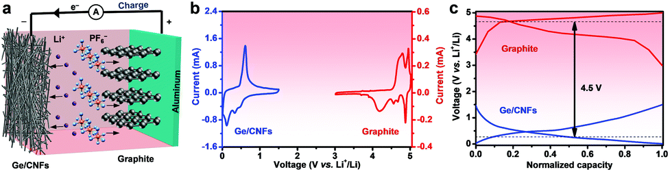 | ||
| Fig. 3 Schematic illustration of the Ge/CNF–G DIB design. (a) Schematic illustration of the charging process of the Ge/CNFs–G DIB. (b) Typical CV curves of the Ge/CNF anode in a voltage range of 0–1.5 V (blue) and the graphite cathode in a voltage range of 3–5 V (red). (c) Charge/discharge profiles of the Ge/CNF half-cell (blue) and graphite half-cell (red). | ||
Then, the electrochemical performance of this rationally designed DIB was elaborately investigated. To enhance the electrochemical performance of the Ge/CNFs–G DIB, different upper cut-off voltages were performed with a fixed discharge cut-off voltage of 2.0 V (Fig. S4a and b†). It can be noted that when the upper cut-off voltage was set below 4.6 V, the Ge/CNFs–G DIB showed a relatively low reversible capacity, but when the upper cut-off voltage was set above 4.6 V, the coulombic efficiency gradually decreased due to the decomposition of the electrolyte under high voltages.51,52 Thus, the upper cut-off voltage of 4.6 V was an appropriate choice owing to its higher reversible capacity and coulombic efficiency. CV measurement was conducted to unveil the electrochemical reaction process of the Ge/CNFs–G DIB (Fig. 4a). Evidently, a pair of redox peaks appeared at 3.5/3.7 V, which can be ascribed to the Ge–Li alloying/de-alloying reactions as well as to the intercalation/deintercalation of PF6− ions into/from the graphite cathode. Moreover, the highly overlapped curves indicate the excellent cycling stability of the Ge/CNFs–G DIB. Fig. 4b shows the galvanostatic charge–discharge data for the Ge/CNFs–G DIB at a discharge current density of 0.25 A g−1, and it could show a reversible capacity of 182 mA h g−1 after 100 cycles. Meanwhile, we tested the cycling performance of DIBs using CNFs as anode materials (CNFs-G) under the same conditions for comparison (Fig. S5†), and the CNFs-G DIB can barely exhibit a discharge capacity of less than 10 mA h g−1 in this voltage window, implying that the capacity contribution in the Ge/CNFs is mainly from Ge. Notably, the Ge/CNF–G DIB also shows excellent cycling stability at a higher discharge current density of 2.5 A g−1, with a reversible specific capacity of 106 mA h g−1 and coulombic efficiency over 98% after 500 cycles. Meanwhile, the morphology of the Ge/CNFs was well preserved without any visible cracking, proving their prominent structural stability (inset in Fig. 4c). Furthermore, the rate performance of the Ge/CNFs–G DIB was tested at various discharge current densities of 0.25, 0.5, 1, 1.5, and 2.5 A g−1, and the discharge capacities were around 281, 209, 172, 136, and 94 mA h g−1, respectively (Fig. 4d). When the discharge current density returned to 0.25 A g−1, the discharge capacity could recover back to 254 mA h g−1. Moreover, upon comparing the rate capability of our Ge/CNFs–G DIB with that of most of the state-of-the-art ones previously reported, in which the capacities were all calculated based on the mass of active materials in the anode (Fig. 4e),52–58 it can be noted that our Ge/CNFs–G DIB can show higher reversible capacity at different discharge current densities.
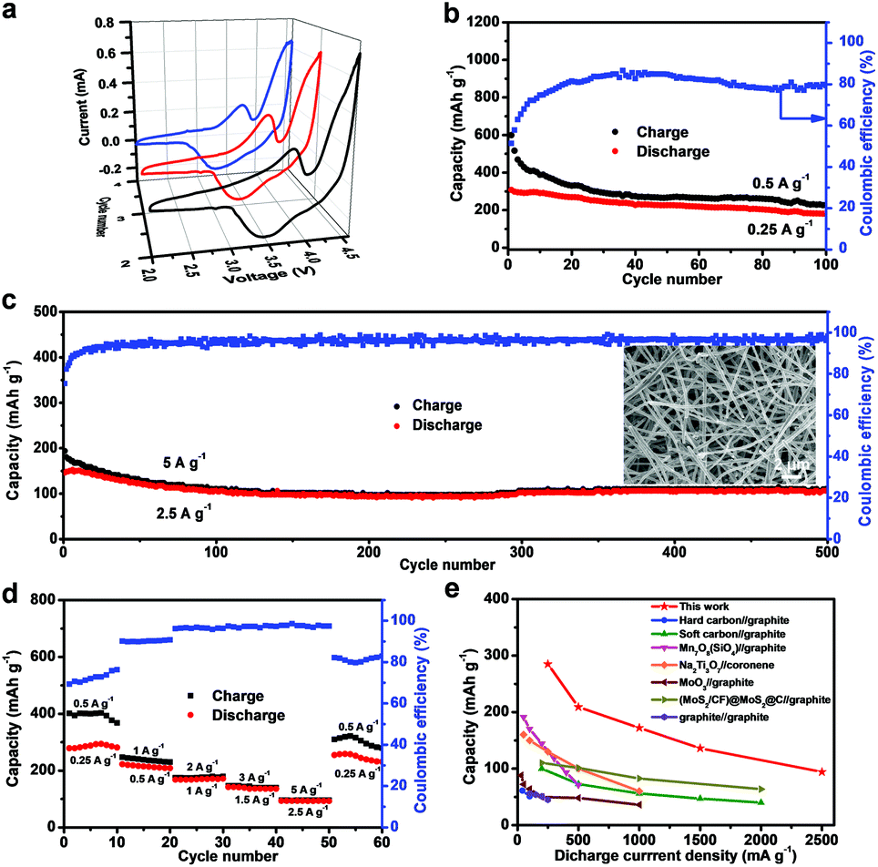 | ||
| Fig. 4 Electrochemical performance of the Ge/CNFs–G DIB. (a) CV curves of the Ge/CNFs–G DIB at a scan rate of 0.5 mV s−1 in a voltage window of 2–4.6 V. Cycling performance of the Ge/CNFs–G DIB at discharge current densities of (b) 0.25 A g−1 and (c) 2.5 A g−1, the inset SEM image shows the Ge/CNF electrode after 500 cycles. (d) Rate capability of the Ge/CNFs–G DIB at different current densities. (e) Comparison of rate performance between the Ge/CNFs–G DIB and reported DIBs (all capacities in the figure are calculated based on the mass of active materials in the anode). | ||
Finally, the working mechanism of the Ge/CNFs–G DIB was studied by a series of characterization techniques. The TEM image of a single Ge/CNF after the initial cycle shows that the one-dimensional nanostructure can still be maintained, indicating the excellent structural stability of the Ge/CNFs (Fig. 5a). The SEAD pattern (inset in Fig. 5a) shows a diffusing ring, demonstrating the transformation of the crystalline Ge into amorphous Ge.59 Additionally, the elemental mapping of the discharged Ge/CNFs was also performed (Fig. 5b), and the homogeneous distribution of F and P elements implied the formation of SEI layers. Ge remained embedded in the carbon matrix after cycling, further confirming the good chemical stability of the Ge/CNFs. Meanwhile, Fig. 5c shows the Nyquist plots of the Ge/CNFs–G DIB for the initial five cycles at a discharge current of 0.25 A g−1; no obvious increase in resistance was observed, implying the good cycling stability of the Ge/CNFs–G DIB. Furthermore, ex situ XPS analysis was conducted on the Ge/CNFs at different stages to clarify their charge storage mechanism. In the Ge 3d spectra (Fig. 5d), after the initial charging process, the Ge–Ge bond showed an evident shift to lower binding energies, which may be due to the formation of LixGe alloys.60 In addition, the Ge–C bond was still retained after the charging/discharging process, suggesting the stable chemical bonding between Ge and the carbon matrix.61 Moreover, ex situ XRD characterization was conducted to further understand the structural evolution of the Ge/CNFs during the charging/discharging process (Fig. 5e and f). After the Ge/CNF–G DIB was charged to 3.7 V, only the Ge (111) peak was still visible with decreased intensity, which is consistent with the initial crystalline Ge alloying with Li and the formation of LixGe alloys. As the voltage increased to 4.2 V, all Ge peaks disappeared and only a broad peak corresponding to the amorphous carbon matrix can be observed, indicating that Ge has completely alloyed with Li and the final products of LixGe alloys are amorphous. It is worth noting that the Ge/CNFs remained amorphous during the subsequent cycles.62,63 Based on the above achieved results, the working mechanism of the Ge/CNFs–G DIB can be concluded as follows: upon alloying with Li, the initial crystalline Ge undergoes a phase transformation forming amorphous LixGe alloys, and then the amorphous LixGe alloys are converted into amorphous Ge through the de-alloying process, as shown in Fig. 5g. Moreover, the redox reactions for our Ge/CNFs–G DIB during the charging/discharging process are given as follows:
For the anode:
| Ge + xLi+ + xe− ↔ LixGe |
For the cathode:
| xC + PF6− ↔ Cx(PF6) + xe− |
For the full cell:
| Ge + xLi+ + xC + PF6− ↔ Cx(PF6) + LixGe |
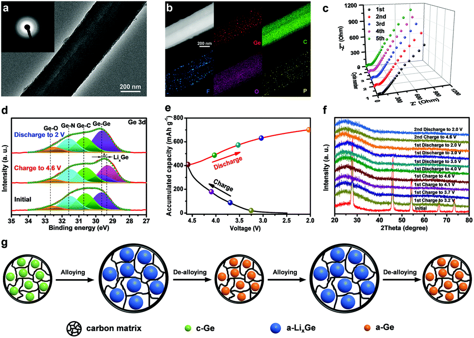 | ||
| Fig. 5 The working mechanism of the Ge/CNFs–G DIB. (a) TEM image and SAED pattern (inset) of the Ge/CNF electrode after the first cycle. (b) HAADF-STEM image of the Ge/CNF electrode after the first cycle and the corresponding elemental mapping images of Ge, C, F, O and P, respectively. (c) The Nyquist plots of the Ge/CNFs–G DIB for the initial five cycles. (d) High-resolution XPS spectra of Ge 3d at different states. (e) Typical charge/discharge profiles of the Ge/CNFs–G DIB. (f) Ex situ XRD patterns of the Ge/CNF electrode during the first and second cycle. (g) Proposed schematic to reveal the phase transformation for the Ge/CNF electrode during the cycling process. | ||
Conclusions
In summary, a novel Ge-based DIB employing Ge/CNFs as anode materials has been reported for the first time. The working mechanism of the Ge/CNFs was revealed to be Ge alloying/de-alloying with Li, accompanied by a phase transition from the initial crystalline Ge to amorphous LixGe alloys and then amorphous Ge during the subsequent cycling processes. Excitingly, this novel Ge/CNF–G DIB shows high discharge capacity (281 mA h g−1 at a discharge current density of 0.25 A g−1), superb rate performance and superior cycling stability (500 cycles with a capacity retention of 74.2% at a discharge current density of 2.5 A g−1) over a high potential window of 2–4.6 V. More impressively, the electrochemical performance of the Ge/CNFs–G DIB greatly exceeds that of most of the reported DIBs, which can be attributed to the following advantages: (1) the high theoretical capacity of Ge; (2) the shorter lithium-ion diffusion distance of a one-dimensional nanostructure; and (3) the carbon matrix which can alleviate the volume expansion of Ge during the cycling process and enhance the electrical conductivity of the Ge/CNFs. We believed that this finding will promote the use of novel electrode materials and nano-architectures in DIBs and speed-up the development of DIBs for practical applications.Conflicts of interest
There are no conflicts to declare.Acknowledgements
This work is financially supported by the National Natural Science Foundation of China (51772049, 51822201 and U1804138) and the 111 Project (B14009).References
- M. Armand and J.-M. Tarascon, Nature, 2008, 451, 652 CrossRef CAS PubMed.
- G. Qu, J. Wang, G. Liu, B. Tian, C. Su, Z. Chen, J. P. Rueff and Z. Wang, Adv. Funct. Mater., 2019, 29, 1805227 CrossRef.
- Q. Yang, F. Mo, Z. Liu, L. Ma, X. Li, D. Fang, S. Chen, S. Zhang and C. Zhi, Adv. Mater., 2019, 31, 1901521 CrossRef PubMed.
- J. Y. Luo, W. J. Cui, P. He and Y. Y. Xia, Nat. Chem., 2010, 2, 760 CrossRef CAS PubMed.
- L. Lu, X. Han, J. Li, J. Hua and M. Ouyang, J. Power Sources, 2013, 226, 272–288 CrossRef CAS.
- J. Luo, C. Wang, H. Wang, X. Hu, E. Matios, X. Lu, W. Zhang, X. Tao and W. Li, Adv. Funct. Mater., 2019, 29, 1805946 CrossRef.
- Z. Liu, Q. Yang, D. Wang, G. Liang, Y. Zhu, F. Mo, Z. Huang, X. Li, L. Ma, T. Tang, Z. Lu and C. Zhi, Adv. Energy Mater., 2019 DOI:10.1002/aenm.201902473.
- J. B. Goodenough and K.-S. Park, J. Am. Chem. Soc., 2013, 135, 1167–1176 CrossRef CAS PubMed.
- X. Tong, F. Zhang, G. Chen, X. Liu, L. Gu and Y. Tang, Adv. Energy Mater., 2018, 8, 1701967 CrossRef.
- J. A. Read, A. V. Cresce, M. H. Ervin and K. Xu, Energy Environ. Sci., 2014, 7, 617–620 RSC.
- M. Wang, C. Jiang, S. Zhang, X. Song, Y. Tang and H. M. Cheng, Nat. Chem., 2018, 10, 667–672 CrossRef CAS PubMed.
- S. Miyoshi, H. Nagano, T. Fukuda, T. Kurihara, M. Watanabe, S. Ida and T. Ishihara, J. Electrochem. Soc., 2016, 163, A1206–A1213 CrossRef CAS.
- K. Beltrop, S. Beuker, A. Heckmann, M. Winter and T. Placke, Energy Environ. Sci., 2017, 10, 2090–2094 RSC.
- T. Ishihara, Y. Yokoyama, F. Kozono and H. Hayashi, J. Power Sources, 2011, 196, 6956–6959 CrossRef CAS.
- K. Beltrop, P. Meister, S. Klein, A. Heckmann, M. Grünebaum, H.-D. Wiemhöfer, M. Winter and T. Placke, Electrochim. Acta, 2016, 209, 44–55 CrossRef CAS.
- S. Rothermel, P. Meister, G. Schmuelling, O. Fromm, H.-W. Meyer, S. Nowak, M. Winter and T. Placke, Energy Environ. Sci., 2014, 7, 3412–3423 RSC.
- K. V. Kravchyk, P. Bhauriyal, L. Piveteau, C. P. Guntlin, B. Pathak and M. V. Kovalenko, Nat. Commun., 2018, 9, 4469 CrossRef PubMed.
- P. Qin, M. Wang, N. Li, H. Zhu, X. Ding and Y. Tang, Adv. Mater., 2017, 29, 1606805 CrossRef PubMed.
- X. Tong, F. Zhang, B. Ji, M. Sheng and Y. Tang, Adv. Mater., 2016, 28, 9979–9985 CrossRef CAS PubMed.
- M. Zhang, L. Xiang, M. Galluzzi, C. Jiang, S. Zhang, J. Li and Y. Tang, Adv. Mater., 2019, 31, 1900826 CrossRef PubMed.
- X. Zhou, Q. Liu, C. Jiang, B. Ji, X. Ji, Y. Tang and H. M. Cheng, Angew. Chem., Int. Ed., 2019 DOI:10.1002/anie.201814294.
- C. K. Chan, X. F. Zhang and Y. Cui, Nano Lett., 2008, 8, 307–309 CrossRef CAS PubMed.
- G. Song, J. Y. Cheong, C. Kim, L. Luo, C. Hwang, S. Choi, J. Ryu, S. Kim, W. J. Song, H. K. Song, C. Wang, I. D. Kim and S. Park, Nat. Commun., 2019, 10, 2364 CrossRef PubMed.
- J. Liu, K. Song, C. Zhu, C.-C. Chen, P. A. van Aken, J. Maier and Y. Yu, ACS Nano, 2014, 8, 7051–7059 CrossRef CAS PubMed.
- T. Kennedy, E. Mullane, H. Geaney, M. Osiak, C. O'Dwyer and K. M. Ryan, Nano Lett., 2014, 14, 716–723 CrossRef CAS PubMed.
- R. Mo, D. Rooney, K. Sun and H. Y. Yang, Nat. Commun., 2017, 8, 13949 CrossRef CAS PubMed.
- D. J. Xue, S. Xin, Y. Yan, K. C. Jiang, Y. X. Yin, Y. G. Guo and L. J. Wan, J. Am. Chem. Soc., 2012, 134, 2512–2515 CrossRef CAS PubMed.
- X. Li, J. Liang, Z. Hou, Y. Zhu, Y. Wang and Y. Qian, Chem. Commun., 2015, 51, 3882–3885 RSC.
- G. Cui, L. Gu, L. Zhi, N. Kaskhedikar, P. A. van Aken, K. Müllen and J. Maier, Adv. Mater., 2008, 20, 3079–3083 CrossRef CAS.
- W. Li, J. Zheng, T. Chen, T. Wang, X. Wang and X. Li, Chem. Commun., 2014, 50, 2052–2054 RSC.
- Q. Ma, W. Wang, P. Zeng and Z. Fang, Langmuir, 2017, 33, 2141–2147 CrossRef CAS PubMed.
- J. Xu, N. Yang, S. Heuser, S. Yu, A. Schulte, H. Schönherr and X. Jiang, Adv. Energy Mater., 2019, 9, 1803623 CrossRef.
- R. Hao, H. Lan, C. Kuang, H. Wang and L. Guo, Carbon, 2018, 128, 224–230 CrossRef CAS.
- B. Wang, J. Jin, X. Hong, S. Gu, J. Guo and Z. Wen, J. Mater. Chem. A, 2017, 5, 13430–13438 RSC.
- W. Wang, Y. Xiao, X. Wang, B. Liu and M. Cao, ChemSusChem, 2014, 7, 2914–2922 CrossRef CAS PubMed.
- D. T. Ngo, R. S. Kalubarme, H. T. T. Le, J. G. Fisher, C.-N. Park, I.-D. Kim and C.-J. Park, Adv. Funct. Mater., 2014, 24, 5291–5298 CrossRef CAS.
- W. Wei, H. Wang, A. Tian, K. Wang, J. Wang, P. Qu, S. Zhang and L. Guo, Nanoscale, 2018, 10, 6872–6877 RSC.
- S. Zhang, Y. Zheng, X. Huang, J. Hong, B. Cao, J. Hao, Q. Fan, T. Zhou and Z. Guo, Adv. Energy Mater., 2019, 9, 1900081 CrossRef.
- Y. W. Lee, D. M. Kim, S. J. Kim, M. C. Kim, H. S. Choe, K. H. Lee, J. I. Sohn, S. N. Cha, J. M. Kim and K. W. Park, ACS Appl. Mater. Interfaces, 2016, 8, 7022–7029 CrossRef CAS PubMed.
- M.-H. Seo, M. Park, K. T. Lee, K. Kim, J. Kim and J. Cho, Energy Environ. Sci., 2011, 4, 425–428 RSC.
- X. Wang, R. A. Susantyoko, Y. Fan, L. Sun, Q. Xiao and Q. Zhang, Small, 2014, 10, 2826–2829 CrossRef CAS PubMed.
- K. Tang, R. J. White, X. Mu, M. M. Titirici, P. A. van Aken and J. Maier, ChemSusChem, 2012, 5, 400–403 CrossRef CAS PubMed.
- D. Li, H. Wang, H. K. Liu and Z. Guo, Adv. Energy Mater., 2016, 6, 1501666 CrossRef.
- G. Wang, M. Yu, J. Wang, D. Li, D. Tan, M. Löffler, X. Zhuang, K. Müllen and X. Feng, Adv. Mater., 2018, 30, 1800533 CrossRef PubMed.
- S. S. Zhang, K. Xu and T. R. Jow, Electrochim. Acta, 2004, 49, 1057–1061 CrossRef CAS.
- G. Yang, H. Wang, B. Zhang, S. Foo, M. Ma, X. Cao, J. Liu, S. Ni, M. Srinivasan and Y. Huang, Nanoscale, 2019, 11, 9556–9562 RSC.
- Y. Tang, Y. Zhang, J. Deng, D. Qi, W. R. Leow, J. Wei, S. Yin, Z. Dong, R. Yazami, Z. Chen and X. Chen, Angew. Chem., Int. Ed., 2014, 53, 13488–13492 CrossRef CAS PubMed.
- Q. Liu, Z. F. Li, Y. Liu, H. Zhang, Y. Ren, C. J. Sun, W. Lu, Y. Zhou, L. Stanciu, E. A. Stach and J. Xie, Nat. Commun., 2015, 6, 6127 CrossRef PubMed.
- S. Bellani, F. Wang, G. Longoni, L. Najafi, R. Oropesa-Nunez, A. E. Del Rio Castillo, M. Prato, X. Zhuang, V. Pellegrini, X. Feng and F. Bonaccorso, Nano Lett., 2018, 18, 7155–7164 CrossRef CAS PubMed.
- J. Seel and J. Dahn, J. Electrochem. Soc., 2000, 147, 892–898 CrossRef CAS.
- C. Li, Y. Ju, H. Yoshitake, M. Yoshio and H. Wang, Mater. Today Energy, 2018, 8, 174–181 CrossRef.
- L. Fan, Q. Liu, S. Chen, Z. Xu and B. Lu, Adv. Energy Mater., 2017, 7, 1602778 CrossRef.
- Z. Hu, Q. Liu, K. Zhang, L. Zhou, L. Li, M. Chen, Z. Tao, Y. M. Kang, L. Mai, S. L. Chou, J. Chen and S. X. Dou, ACS Appl. Mater. Interfaces, 2018, 10, 35978–35983 CrossRef CAS PubMed.
- S. M. Hao, J. Qu, W. Chang, Y. J. Zhang, Y. Tang and Z. Z. Yu, ChemElectroChem, 2019, 6, 1040–1046 CrossRef CAS.
- S. Dong, Z. Li, I. A. Rodríguez-Pérez, H. Jiang, J. Lu, X. Zhang and X. Ji, Nano Energy, 2017, 40, 233–239 CrossRef CAS.
- N. Gunawardhana, G.-J. Park, A. K. Thapa, N. Dimov, M. Sasidharan, H. Nakamura and M. Yoshio, J. Power Sources, 2012, 203, 257–261 CrossRef CAS.
- C. Cui, Z. Wei, J. Xu, Y. Zhang, S. Liu, H. Liu, M. Mao, S. Wang, J. Ma and S. Dou, Energy Storage Mater., 2018, 15, 22–30 CrossRef.
- L. Fan, Q. Liu, S. Chen, K. Lin, Z. Xu and B. Lu, Small, 2017, 13, 1701011 CrossRef PubMed.
- X. H. Liu, S. Huang, S. T. Picraux, J. Li, T. Zhu and J. Y. Huang, Nano Lett., 2011, 11, 3991–3997 CrossRef CAS PubMed.
- K. H. Seng, M. H. Park, Z. P. Guo, H. K. Liu and J. Cho, Nano Lett., 2013, 13, 1230–1236 CrossRef CAS PubMed.
- D. T. Ngo, H. T. T. Le, C. Kim, J.-Y. Lee, J. G. Fisher, I.-D. Kim and C.-J. Park, Energy Environ. Sci., 2015, 8, 3577–3588 RSC.
- C. Kim, G. Song, L. Luo, J. Y. Cheong, S. H. Cho, D. Kwon, S. Choi, J. W. Jung, C. M. Wang, I. D. Kim and S. Park, ACS Nano, 2018, 12, 8169–8176 CrossRef CAS PubMed.
- C. K. Chan, H. Peng, G. Liu, K. McIlwrath, X. F. Zhang, R. A. Huggins and Y. Cui, Nat. Nanotechnol., 2008, 3, 31–35 CrossRef CAS PubMed.
Footnotes |
| † Electronic supplementary information (ESI) available: Details of the synthesis method, sample characterization, electrochemical measurements, calculation process, SEM image of CNFs and electrochemical data. See DOI: 10.1039/c9nr08783d |
| ‡ These authors contributed equally to this work. |
| This journal is © The Royal Society of Chemistry 2020 |