Well-defined CoSe2@MoSe2 hollow heterostructured nanocubes with enhanced dissociation kinetics for overall water splitting†
Zhiwen
Chen‡
 a,
Wenwen
Wang‡
a,
Shoushuang
Huang
a,
Wenwen
Wang‡
a,
Shoushuang
Huang
 *a,
Ping
Ning
a,
Ye
Wu
a,
Chunyan
Gao
a,
Thanh-Tung
Le
a,
Jiantao
Zai
 b,
Yong
Jiang
 a,
Zhangjun
Hu
ac and
Xuefeng
Qian
 b
b
aSchool of Environmental and Chemical Engineering, Shanghai University, Shanghai 200444, People's Republic of China. E-mail: sshuang@shu.edu.cn; Fax: +86 21 66137787; Tel: +86 21 66137503
bShanghai Electrochemical Energy Devices Research Center, School of Chemistry and Chemical Engineering and State Key Laboratory of Metal Matrix Composites, Shanghai Jiao Tong University, Shanghai, 200240, China
cDepartment of Physics, Chemistry and Biology, Linköping University, Linköping, 58183, Sweden
First published on 26th November 2019
Abstract
Hollow heterostructures have tremendous advantages in electrochemical energy storage and conversion areas due to their unique structure and composition characteristics. Here, we report the controlled synthesis of hollow CoSe2 nanocubes decorated with ultrathin MoSe2 nanosheets (CoSe2@MoSe2) as an efficient and robust bifunctional electrocatalyst for overall water splitting in a wide pH range. It is found that integrating ultrathin MoS2 nanosheets with hollow CoSe2 nanocubes can provide abundant active sites, promote electron/mass transfer and bubble release and facilitate the migration of charge carriers. Additionally, the surface electron coupling in the heterostructures enables it to serve as a source of sites for H+ and/or OH− adsorption, thus reducing the activation barrier for water molecules adsorption and dissociation. As a result, the title compound, CoSe2@MoSe2 hollow heterostructures, exhibits an overpotential of 183 mV and 309 mV at a current density of 10 mA cm−2 toward hydrogen evolution reactions and oxygen evolution reactions in 1.0 M KOH, respectively. When applied as both cathode and anode for overall water splitting, a low battery voltage of 1.524 V is achieved along with excellent stability for at least 12 h. This work provides a new idea for the design and synthesis of high-performance catalysts for electrochemical energy storage and conversion.
Introduction
Global environmental pollution and the energy crisis have become a bottleneck restricting the development of international economy and society, which forces people to accelerate the development and utilization of sustainable clean new energy.1–3 Hydrogen is widely considered as one of the most promising energy carriers to traditional petroleum energy by virtue of its clean emissions and low cost-efficiency.4 Electrocatalytic water splitting is a reliable and promising technology for the preparation of high purity hydrogen and oxygen.5 The theoretical thermodynamic potential to drive water splitting is 1.23 V. However, due to the existence of dynamic overpotentials of hydrogen evolution reactions (HER) and oxygen evolution reactions (OER), the efficiency of electrolysis is seriously hindered. In this regard, efficient electrocatalysts are urgently needed to lower the activation barrier and accelerate the catalytic reaction process.6 At present, noble metal-based materials, such as Pt/C, Pd, RuO2 and IrO2, are acknowledged to be the most effective electrocatalysts owing to their low overpotentials and high reaction rates.7 However, their large-scale commercial application is greatly impeded by their low reserves, high cost and easier deactivation. Therefore, it is highly desirable to develop low-cost, efficient and robust alternative catalysts for water splitting both in acid and alkaline media.Recently, the design and synthesis of cost-effective and stable electrocatalysts for electrochemical water splitting have been achieved by optimizing the composition and structure of non-noble metal catalysts, including metal alloys,8 carbon materials9,10 and transition metal compounds.11–13 Among them, cobalt-based chalcogenides with different stoichiometric ratios, such as Co9S8,14 CoS2,15,16 CoSe2,17,18 and CoSxSe2−x,19 have attracted more and more attention in view of many advantages including low toxicity, rich structure chemistry, low overpotential and fast kinetics. For example, Liu et al. prepared atomically thick CoSe2 nanosheets as highly efficient OER catalysts by exfoliating CoSe2-based lamellar compounds.20 It was found that the vacancies (VCo) existing on the surface of CoSe2 nanosheets served as efficient active sites to catalyze the OER, manifesting a low overpotential of 320 mV at 10 mA cm−2 in alkaline media. Liu and co-workers reported that the Co-doped NiSe2 nanoparticle films electrodeposited on conductive Ti plates (Co0.13Ni0.87Se2/Ti) exhibited good HER electrocatalytic activity in 1.0 M KOH, and showed a low overpotential of 64 mV to reach 10 mA cm−2 with a small Tafel slope of 63 mV dec−1.21 Given these facts, cobalt-based selenides are promising electrocatalysts for water splitting. Furthermore, it is widely accepted that a large specific surface area is favorable for catalytic reactions. As an important and useful morphology, a hollow micro-/nanostructure can provide many advantages for constructing highly catalytically active electrocatalysts, such as large exposed surfaces, rich active sites and rapid electron/mass transfer, which are favorable for catalytic reactions. For instance, Yu and co-workers found that Ni and Co incorporated MoS2 nanoboxes manifested impressive HER activity with an onset potential of 125 mV and a Tafel slope of 51 mV dec−1.22 Therefore, the controlled synthesis of hollow nanostructures is a promising way to significantly enhance the catalytic activity of cobalt-based selenides.
Although cobalt selenides, especially CoSe2, have demonstrated promising capabilities as OER catalysts, pure CoSe2 still exhibited unsatisfactory catalytic activity. Besides, pure CoSe2 is not stable in acid electrolytes, implying that it can hardly serve as a bifunctional electrocatalyst for overall water splitting. Coincidentally, recent studies have shown that the construction of heterostructured electrocatalysts via combining HER and OER active nanocomponents together in one system is an effective way to obtain more outstanding electrocatalytic performance. The delicate heterostructures with refined electron distribution not only provide sufficient adsorption sites for the intermediates but also improve electron transfer efficiency at their interface.23,24 These advantages contribute significantly to enhanced HER and OER kinetics, making them efficient bifunctional catalysts for electrochemical water splitting. For example, Yu's group found that the CoSe2/MoS2 heterostructures manifested better HER performance than pure MoS2 in 0.5 M H2SO4 solution with a low overpotential of 68 mV at 10 mA cm−2.25 Lin et al. reported that heterogeneous MoS2/NiS2 nanosheets on carbon cloth displayed enhanced catalytic performance for water splitting, which delivered an overpotential of 62 mV and 278 mV at the current density of 10 mA cm−2 for the HER and OER, respectively.26 Based on these facts, CoSe2-based hollow heterostructures are reasonably expected to be efficient and robust electrocatalysts for overall water splitting in a wide pH range. It is well known that MoS2 and MoSe2 with abundant edge sites are powerful HER catalysts, but they often display limited OER performance. Thus, integration of the CoSe2 hollow nanocubes with an active and stable HER catalyst such as MoSe2 nanosheets into one system is expected to display outstanding catalytic performance for overall water splitting. However, to the best of our knowledge, the controlled synthesis of CoSe2/MoSe2 nanocubes with a well-defined hollow core–shell nanostructure has never been reported.
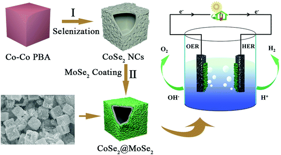
Herein, in the present work, we reported the design and synthesis of hollow CoSe2 nanocubes decorated with ultrathin MoSe2 nanosheets as a cost-effective electrocatalyst for electrochemical overall water splitting. The CoSe2@MoSe2 heterostructures were synthesized by two-step hydrothermal reactions. Firstly, the hollow CoSe2 nanocubes were prepared via a first hydrothermal reaction based on ionic exchange reactions between Co-based Prussian blue analogues (Co3[Co(CN)6]2, denoted as Co–Co PBA) and Na2SeO3. Subsequently, the CoSe2@MoSe2 hollow heterostructures were synthesized through the in situ growth of ultrathin MoSe2 nanosheets on the surface of CoSe2 nanocubes. Benefiting from the merits of structure and compositions, such a delicate structure can provide abundant well-exposed active sites, promote electron/mass transfer and facilitate the migration of charge carriers. As a result, the CoSe2@MoSe2 heterostructures displayed impressive catalytic performance, with an overpotential of 187 mV and 309 mV at a current density of 10 mA cm−2 toward the HER and OER in 1.0 M KOH, respectively. When applied as both cathode and anode for overall water splitting, a low battery voltage of 1.524 V is achieved along with excellent stability for at least 12 h. The results presented here demonstrated that the CoSe2@MoSe2 complex nanocube is a cost-effective and robust bifunctional catalyst for overall water splitting.
Experimental
Synthesis of Co–Co PBA nanocubes
Co–Co PBA nanocubes were synthesized as reported in our previous work.27 In a typical synthesis, 2.0 mmol of K3[Co(CN)6] were dissolved in 100 mL of H2O under vigorous stirring to form a clear solution A. Then, the solution A was uniformly mixed with 100 mL of solution B containing 3.0 mmol C4H6O4Co·4H2O and 4.5 mmol Na3C6H5O7·2H2O. The obtained mixed solution was allowed to age for 20 h at room temperature. Finally, the product was collected by centrifugation and washed with water and ethanol several times before drying at 60 °C overnight.Synthesis of hollow CoSe2 nanocubes
CoSe2 hollow nanocubes were prepared following Fang's procedure with a few modifications.28 Typically, 30 mg of Co–Co PBA nanocubes were uniformly dispersed in 10 mL of H2O under ultrasound. At the same time, 15 mL of a solution in which 60 mg of Na2SeO3·2H2O was dissolved was poured into the above Co–Co PBA suspension and magnetically stirred for 30 min. Then, 1.0 mL of N2H4 was added to the above mixed solution, and stirred for 30 min until the solution was completely mixed. Finally, the mixture was transferred to a Telfon-lined stainless steel autoclave and kept in an oven at 160 °C for 8 h. After the reaction was completed, it was cooled to room temperature. The final product was collected by centrifugation, washed several times with water and ethanol, and then dried under vacuum at 60 °C for 12 h.Synthesis of CoSe2@ hollow MoSe2 heterostructures
CoSe2@MoSe2 hollow heterostructures were obtained by using a facile hydrothermal reaction process. Typically, 50 mg of the as-obtained CoSe2 hollow nanocubes, 65 mg of Na2SeO3·2H2O, 100 mg of Na2MoO3·2H2O were dissolved in 50 mL of N,N-dimethylformamide (DMF) to form a homogeneous suspension with the assistance of ultrasonication for 30 min. The resulting mixture was transferred into a Telfon-lined stainless-steel autoclave and kept at 200 °C for 15 h in an electric oven and then cooled down to room temperature naturally. The final product was collected by centrifugation, washed several times with water and ethanol, and dried overnight under vacuum at 60 °C. The preparation process of pure MoSe2 particles is similar to the above method, except for the addition of CoSe2 hollow nanocubes.Characterization
The phase composition and crystal structure of the obtained samples were analyzed by X-ray diffraction (XRD) on a Rigaku D/MAX RINT-2000 X-ray diffractometer. The morphology and microstructure were examined by field emission scanning electron microscopy (FESEM; JEOL-7600F) and transmission electron microscopy (TEM; JEOL, JEM2100F). The composition and elemental mapping of the samples were analyzed by using an energy dispersive X-ray spectrometer (EDX) attached to a SEM instrument. An X-ray photoelectron spectrometer (XPS, VG Microtech ESCA2000) was used to analyze the compositions and chemical state of the elements in the synthesized sample. The specific surface areas and pore size distribution of the sample were determined by nitrogen adsorption/desorption measurement using a Quantachrome Autosorb-iQ instrument.Electrochemical measurement
The electrocatalytic performance was tested using a standard three-electrode system of an electrochemical workstation (CHI 660e). The acidic and alkaline electrolyte solutions were 0.5 M H2SO4 and 1.0 M KOH, respectively. A platinum mesh and a saturated calomel electrode (SCE) (or a standard Hg/HgO electrode) were used as the counter and reference electrodes in 0.5 M H2SO4 (or 1.0 M KOH). To prepare a working electrode, 3 mg of CoSe2@MoSe2 was dispersed in a mixed solution of 55 μL of ethanol, 165 μL of water and 20 μL of naphthol, and sonicated to obtain a uniform dispersion. Finally, 3 μL or 48 μL of the above liquid was dropped on a glassy carbon electrode (diameter: 3 mm) or nickel foam (1 × 1 cm2) to obtain a CoSe2@MoSe2 modified electrode. Electrodes of CoSe2 hollow nanocubes, MoSe2 microspheres, and 20 wt% Pt/C catalysts were also prepared using the same method for comparison. The polarization curves of OER and HER activity were characterized by linear sweep voltammetry (LSV) with a scan rate of 5 mV s−1. Prior to LSV, each electrode will be activated for 40 cycles at a scan rate of 50 mV s−1. In an acidic and alkaline medium (0.5 M H2SO4 or 1.0 M KOH), all graphs shown are calibrated to the reversible hydrogen electrode (RHE) based on the equation (ERHE = ESCE + 0.059 × pH + 0.241 or ERHE = EHg/HgO + 0.059 × pH + 0.098) and corrected for iR compensation. The overpotential (η) of the OER is calculated according to the following formula: η(V) = ERHE − 1.23 V. The AC impedance test (EIS) was performed at open circuit voltage (10−2 to 104 Hz) with an AC voltage of 5 mV. The electric double layer capacitance (Cdl) of the electrode is measured by cyclic voltammetry (CV), and the illegal pull-over overvoltage range is 0.1 to 0.2 (1.3 to 1.4 V) (vs. RHE at 0.5 M H2SO4 or 1.0 M KOH) with a sweep rate of 20–200 mV s−1.Results and discussion
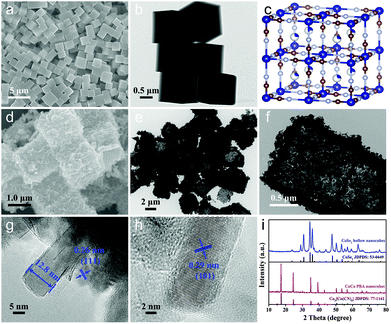
The schematic diagram for preparing CoSe2@MoSe2 hollow heterostructures is shown in Fig. 1. First, highly uniform Co–Co PBA nanocubes were synthesized as templates through a facile coprecipitation method. Then, these solid Co–Co PBA nanocrystals were successfully converted into nanoplate-assembled CoSe2 hollow nanoboxes via a simple anion-exchange reaction between Co–Co PBA nanocubes and Na2SeO3 at elevated temperatures. Afterwards, the CoSe2@MoSe2 hollow heterostructures were prepared by in situ growth of ultrathin MoSe2 nanosheets on the surface of hollow CoSe2 nanocubes via a facile hydrothermal method.The typical scanning electron microscopy (SEM) image in Fig. 2a showed that the as-synthesized Co–Co PBA nanocubes were uniform and the average size was ca. 1 μm. The corresponding transmission electron microscopy (TEM) image in Fig. 2b indicated that these Co–Co PBA nanocubes had a solid texture with a smooth surface. The Co–Co PBA nanocubes were then used as sacrifice templates to prepare CoSe2 hollow nanoboxes. It can be seen that the CoSe2 nanocubes still maintained the cubic structure of the Co–Co PBA nanocubes (Fig. 2d), but its surface became very rough. The obvious contrast differences in the TEM image demonstrated that the CoSe2 nanoboxes had a distinct hollow structure (Fig. 2e), which was favorable to promote electron/mass transfer and bubble release. The magnified TEM image of one single CoSe2 nanocube indicated that the shell was composed of randomly assembled nanoplates, and the thickness of the shell was ∼150 nm (Fig. 2f). This result indicated that the morphology of Co–Co PBA changed significantly during the selenization process, which agreed well with Fang's results.28 The formation of hollow CoSe2 nanocubes can be explained by the Kirkendall effect. In the early stages of selenization, the Se2− ion reacted with CoCo PBA nanocubes, resulting in the formation of a thin layer of CoSe2 nanocrystallites on the surface. The size of Se2− is larger than that of Co2+, thus the inward diffusion of Se2− ions was slower than the outward diffusion of Co2+ ions, leading to the reactions mainly taking place on the preformed CoSe2 shell and finally the formation of hollow CoSe2 nanocubes.29 Form the high-resolution TEM (HRTEM) image of a CoSe2 layer, we can infer that the thickness of the CoSe2 nanoplate is about 12.8 nm (Fig. 2g). The lattice spacing of the plane was ca. 0.29 nm, which could be indexed to the (101) face of CoSe2 (Fig. 2h). To explore structure changes during the synthesis processes, the phase composition and crystal structure of the products were characterized by X-ray diffraction (XRD) measurements (Fig. 2i). It can be seen that all characteristic peaks of the as-prepared Co–Co PBA nanocubes are basically consistent with the previous work.30 After the selenidation reaction, new strong diffraction peaks can be clearly observed, illustrating the high crystallinity of the product. Additionally, all the diffraction peaks corresponded to the orthorhombic structure of CoSe2 (JCPDS no. 53-0449). No diffraction peaks of impurities could be observed, indicating that the Co–Co PBA nanocubes were completely transformed into hollow CoSe2 nanocubes.
The CoSe2@MoSe2 hollow heterostructures were controllably synthesized by the in situ growth of ultrathin MoSe2 nanosheets on the surface of hollow CoSe2 nanoboxes. The composition and crystal structure of the CoSe2@MoSe2 heterostructures were firstly investigated by XRD analysis. As shown in Fig. 3a, the diffraction peaks of CoSe2 can still be observed. In addition, some new peaks marked with clubs at 13.7°, 31.4°, 37.9° and 55.9° could be attributed to the (002), (100), (103) and (110) planes of hexagonal phase MoSe2 (JCPDS No. 29-0914, a = b = 3.287 Å, c = 12.925 Å), respectively.31 This result indicates that the as-obtained sample consists of CoSe2 and MoSe2. X-ray photoelectron spectroscopy (XPS) was then performed to determine the chemical state of the elements in the CoSe2@MoSe2 sample. The survey spectrum in Fig. S1† indicates the presence of Co, Mo, and Se in the sample. Fig. 3b–d present the high-resolution XPS spectrum of Co 2p, Mo 3d and Se 3d, respectively. As shown in Fig. 3b, the peak of Co 2p3/2 could be deconvoluted into two peaks at 778.3 and 780.3 eV, and the peak of Co 2p1/2 could be divided into two peaks at 793.2 and 796.4 eV.32 The peaks at 778.3 and 793.2 eV were attributed to the Co–Se bonding configuration, and the peaks at 780.3 and 796.4 eV implied the presence of a Co–O bonding configuration. Compared to that of pure CoSe2, the peak of the Co 2p spectrum displays a positive shift of nearly 0.2 eV, suggesting the existence of strong electronic interactions between CoSe2 and MoSe2 (Fig. S2†).33 For the Mo 3d spectrum, the strong peaks located at the binding energies of 228.4 and 231.7 eV correspond to Mo 3d3/2 and Mo 3d5/2 of Mo4+ species, respectively.34 Meanwhile, the two small peaks at 232.3 and 235.3 could be attributed to Mo6+ from Na2SeO4 or MoO3 formed on the surface of MoSe2. The other peak at 229.5 eV could be assigned to Se 3s of MoSe2. Fig. 3d displays a high resolution Se 3d spectrum, the binding energies of 54.1 and 54.9 eV corresponding to the Se 3d5/2 and Se 3d3/2 could be assigned to the Se anion in pyrite CoSe2.35 The observed peak of 59.4 eV could be attributed to the SeO bond due to the weak oxidation of the sample.36 The XPS characterization was in agreement with the XRD result, suggesting the successful synthesis of CoSe2@MoSe2 hybrids.
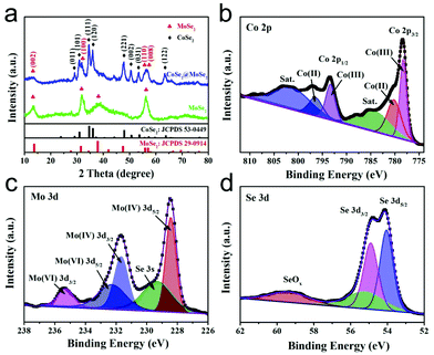 | ||
| Fig. 3 XRD pattern (a) of the as-formed CoSe2@MoSe2 heterostructures. High-resolution XPS spectra of Co 2p (b), Mo 3d (c) and Se 3d (d) in the CoSe2@MoSe2 heterostructures. | ||
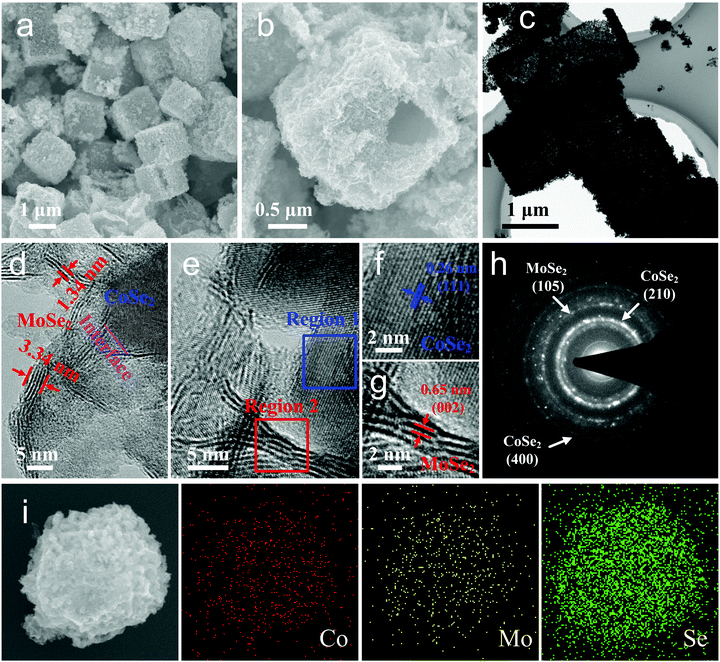
The atomic structures, morphology details and crystal quality of the as-obtained CoSe2@MoSe2 hollow heterostructures were further explored by SEM and TEM measurements. As shown in the SEM images presented in Fig. 4a and b, the surface of the CoSe2@MoSe2 heterostructures was rather rough, and the hollow interior could be clearly observed from the cracked particle. This unique hollow structure can also be confirmed by the low magnification TEM characterization shown in Fig. 4c. The magnified TEM image in Fig. 4d shows that many two-dimensional MoSe2 nanosheets were distributed on the surface of the CoSe2 nanosheets by forming a heterostructure. The close contact with each other could enhance the charge transfer during the catalytic reaction process.37 Additionally, from the edge view shown in Fig. 4e, we can see that the thickness of MoSe2 nanosheets was in the range of 1–4 nm. The ultrathin MoSe2 nanosheets with maximized exposed edges were conducive to exposing the catalytic sites and accelerating the catalytic reactions.38Fig. 4f displays the HRTEM image of a CoSe2 layer, corresponding to region 1 marked in Fig. 4e. The clear lattice fringe addressed the high crystalline nature of the CoSe2 nanoplates. The interlayer spacing of the plane was 0.26 nm, which well agreed with the (111) plane of CoSe2. The HRTEM image in Fig. 4g, corresponding to region 2 displayed in Fig. 4e, displayed a typical edge view of 4-layer MoSe2 nanosheets which were curly and deviated from the vertical direction. The lattice spacing was about 0.65 nm, which could be indexed to the (002) face of the 2H-MoSe2 phase. From the edge view, we can see that the MoSe2 nanosheets are open structures with edge-termination. This unique structure meant that the MoSe2 nanosheets were defect-rich and mainly dominated by edges with a high density of exposed edge sites and catalytically active sites, which could enhance the catalytic activity of the HER and OER.39 The corresponding annular selected area electron diffraction (SAED) patterns can be indexed to the (210), (400) and (105) planes of CoSe2 and MoSe2, which was consistent with the HRTEM results.40 Energy dispersive X-ray spectroscopy (EDX) showed the Co![[thin space (1/6-em)]](https://www.rsc.org/images/entities/char_2009.gif) :
:![[thin space (1/6-em)]](https://www.rsc.org/images/entities/char_2009.gif) Mo
Mo![[thin space (1/6-em)]](https://www.rsc.org/images/entities/char_2009.gif) :
:![[thin space (1/6-em)]](https://www.rsc.org/images/entities/char_2009.gif) Se atomic ratio to be 3.3
Se atomic ratio to be 3.3![[thin space (1/6-em)]](https://www.rsc.org/images/entities/char_2009.gif) :
:![[thin space (1/6-em)]](https://www.rsc.org/images/entities/char_2009.gif) 1
1![[thin space (1/6-em)]](https://www.rsc.org/images/entities/char_2009.gif) :
:![[thin space (1/6-em)]](https://www.rsc.org/images/entities/char_2009.gif) 6.7 (Fig. S3†). The elemental mapping images confirmed that these elements were uniformly distributed in a single nanocube (Fig. 4i). Based on the above analysis, it can be concluded that the resulting product consisted of CoSe2 and MoSe2. The CoSe2@MoSe2 hollow heterostructure possessed a specific surface area of 59.124 m2 g−1 with a narrow pore size distribution centered at 38.2 nm, exhibiting an obvious mesoporous structure (Fig. S4†).
6.7 (Fig. S3†). The elemental mapping images confirmed that these elements were uniformly distributed in a single nanocube (Fig. 4i). Based on the above analysis, it can be concluded that the resulting product consisted of CoSe2 and MoSe2. The CoSe2@MoSe2 hollow heterostructure possessed a specific surface area of 59.124 m2 g−1 with a narrow pore size distribution centered at 38.2 nm, exhibiting an obvious mesoporous structure (Fig. S4†).
HER performances of the as-prepared electrocatalysts
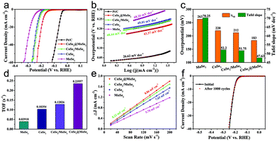
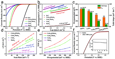
The as-obtained catalysts were firstly dripped on glassy carbon electrodes for the linear sweep voltammetry (LSV) electrochemical test in 0.5 M H2SO4 solution to evaluate their HER performance. All the plots were corrected by 90% iR-compensation. As shown in Fig. 5a, the current density increased rapidly under more negative potentials, suggesting the excellent HER activity of the as-synthesized samples. Particularly, the overpotential of the CoSe2@MoSe2 catalyst at the current density of 10 mA cm−2 was 183 mV, remarkably smaller than that of the CoSe2 (220 mV). This comparison revealed that the in situ growth of MoSe2 on CoSe2 nanocubes to form heterostructures could effectively improve the HER electrocatalytic reactivity.41 To support this conclusion, pure MoSe2 microspheres (Fig. S5†) and physically mixed CoSe2 and MoSe2 hybrids (denoted as CoSe2/MoSe2) were also prepared. It was found that their activities were obviously lower than that of CoSe2@MoSe2 hollow heterostructures. The 20 wt% Pt/C electrocatalysts exhibited the highest HER electrocatalytic activity with a low overpotential of 206 mV vs. RHE at 10 mA cm−2. To gain insight into the rate-determining step during the HER process, the Tafel diagram was further analyzed (Fig. 5b). The specific overpotential at 10 mA cm−2 current density (η10) and the corresponding Tafel slope of different samples are displayed in Fig. 5c. The extracted Tafel slope of CoSe2@MoSe2 heterostructures was 43.37 mV dec−1, outperforming those of CoSe2 (49.01 mV dec−1), MoSe2 (68.26 mV dec−1) and CoSe2/MoSe2 (48.44 mV dec−1). The lower overpotential and smaller Tafel slope of CoSe2@MoSe2 heterostructures indicated that they had faster HER kinetics and higher catalytic performance. It is well known that the Tafel slopes of 120, 40 and 30 mV dec−1 correspond to the Volmer reaction, Heyrovsky reaction and Tafel reaction for the HER catalytic process in acidic electrolytes, respectively.42 In the present work, the Tafel slope of CoSe2@MoSe2 was close to 43.37 mV dec−1, suggesting that the Volmer–Heyrovsky mechanism was the rate-limiting step during the HER process.43 To investigate the origin of the high electrocatalytic activity of CoSe2@MoSe2 heterostructures, the electrochemically active surface area (ECSA) of catalysts was measured by double-layer capacitance (Cdl) in cyclic voltammetry (CV). Fig. 5c and S4† show the CV curves of MoSe2, CoSe2 and CoSe2/MoSe2 at different scanning rates of 20–200 mV s−1 in the range of 100–200 mV (vs. RHE) voltage. Cdl is determined by plotting the curve of ΔJ (ΔJ = Janodic − Jcathodic) relative to RHE at a voltage of 150 mV, and the Cdl value of the sample is the linear slope of the curve. The Cdl value of CoSe2@MoSe2 was 8.86 mF cm−2, much higher than that of MoSe2 (5.78 mF cm−2), CoSe2 (7.65 mF cm−2) and CoSe2/MoSe2 (8.22 mF cm−2), suggesting the existence of more active sites in the CoSe2@MoSe2 heterostructures.22 To further understand the intrinsic electrocatalytic activities of these electrocatalysts, the turnover frequency (TOF) at an overpotential of 300 mV was calculated. It can be seen that the CoSe2@MoSe2 exhibited the highest value of 0.23557 s−1, larger than that of CoSe2 (0.10354 s−1), MoSe2 (0.03918 s−1) and CoSe2/MoSe2 (0.12826 s−1). This result confirmed that the synergistic modulation of both active sites and electronic structures could effectively improve the electrocatalytic activity of catalysts. The electrocatalytic stability of electrocatalysts is one of the important parameters for evaluating their practical applications. Thus, the LSV curves were recorded between −0.45 V and 0 V vs. RHE at a scan rate of 100 mV s−1 for 1500 cycles in 0.5 M H2SO4. As shown in Fig. 4f, the LSV curve of CoSe2@MoSe2 was basically the same as the initial curve after 1500 cyclic voltammetry cycles, which directly indicated that the sample had superior cyclic stability. All of these results confirmed that the ideally designed CoSe2@MoSe2 heterostructures had outstanding HER electrocatalytic performance in acidic solution.We also tested the HER performance under alkaline conditions. Fig. 6a and b show the representative iR-corrected LSV polarization curves and Tafel slopes of the as-synthesized catalysts in 1.0 M KOH with Ni foam as substrates. The η10 and corresponding Tafel slopes in each case are illustrated in Fig. 6c. The CoSe2@MoSe2 exhibited obviously superior HER activity with a η10 of 183 mV, which was lower than those of MoSe2 (256 mV), CoSe2 (238 mV), CoSe2/MoSe2 (304 mV). Although it is inferior to commercial Pt/C (58 mV), it was comparable to or better than other cobalt-based selenide catalysts in alkaline media (Table S1†). The Tafel slope of CoSe2@MoSe2 was 87.69 mV dec−1, considerably smaller than that of MoSe2 (144.23 mV dec−1), CoSe2 (130.14 mV dec−1) and CoSe2/MoSe2 (99.96 mV dec−1). This indicated that the CoSe2@MoSe2 catalyst had faster kinetics and higher HER activity even under alkaline conditions. As shown in Fig. 6c and Fig. S6,† the Cdl value of CoSe2@MoSe2 (38.58 mF cm−2) was much larger than that of bare MoSe2 (3.44 mF cm−2), CoSe2 (9.44 mF cm−2) and CoSe2/MoSe2 (28.33 mF cm−2). The experimental results implied that the active surface area of CoSe2@MoSe2 was the largest in the four catalysts. Additionally, the TOF value of CoSe2/MoSe2 was larger than that of CoSe2, MoSe2 and CoSe2/MoSe2 at the same overpotential, revealing the better intrinsic HER activity of CoSe2/MoSe2 (Fig. 6e). The polarization curve of CoSe2@MoSe2 after 1500 cycles was almost the same as the initial curve under alkaline conditions (Fig. 6f), implying that the CoSe2@MoSe2 catalyst also had good cyclic stability in alkaline solution.44 The long-term durability test for the CoSe2@MoSe2 catalyst was performed by controlled potential electrolysis at a static potential of 0.206 V vs. RHE for 12 h. As shown in the inset of Fig. 6f, the current density basically remained at 10 mA cm−2 for the initial 6 h, and then slightly boosted, which can be attributed to the activation process and the increase of the electro-active species. Afterwards, the current density barely decreased, indicating that the electrode can maintain steady HER activity over a period of 12 h.
Evaluation of the oxygen evolution reaction
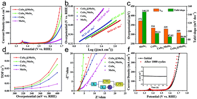
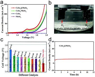
The OER activities of the MoSe2, CoSe2, CoSe2/MoSe2 and CoSe2@MoSe2 samples were examined by LSVs in 1.0 M KOH solution at room temperature, and their polarization curves are displayed in Fig. 7a. The oxidation peak in the range of 1.35–1.40 V vs. RHE is attributed to the precatalytic oxidation of Co2+ to Co3+, indicating the high electrocatalytic activity of the as-fabricated samples.45 The CoSe2@MoSe2 electrode showed better OER catalytic activity compared to its singe component, and the overpotential of η10 was as low as 309 mV. Moreover, the CoSe2@MoSe2 had a lower overpotential of 382 mV at a current density of 50 mA cm−2 (η50) than the bare CoSe2 (399 mV) and MoSe2 (477 mV), indicating a high exposure of the active edge sites in the CoSe2@MoSe2 hybrids. The OER kinetics of catalysts was also explored by using Tafel plots as shown in Fig. 7b. The slope of CoSe2@MoSe2 of 84.04 mV dec−1 was also smaller than that of MoSe2, CoSe2, and CoSe2/MoSe2, indicating a much better kinetic process (Fig. 7c). The TOF of the CoSe2@MoSe2 sample was much bigger than those of MoSe2, CoSe2, and CoSe2/MoSe2 (Fig. 7d). This comparison suggested an increase of the surface area, which clearly affirmed higher active surface areas and better exposure of the catalytic active sites of the CoSe2@MoSe2 (Fig. S7†). To investigate the reaction kinetics of the as-prepared catalysts, electrochemical impedance spectroscopy (EIS) measurements were performed in the frequency range of 0.01–104 Hz. As shown in Fig. 7e (Fig. S8†), the semicircular characteristic of the EIS curve indicated that the charge transfer resistance of CoSe2@MoSe2 was significantly smaller than that of MoSe2, CoSe2 and CoSe2/MoSe2, implying the high catalytic activity of the CoSe2@MoSe2 sample.22 In addition to excellent electrocatalytic activity, CoSe2@MoSe2 also had good stability and durability. The LSV curves were recorded between 1.204 V and 1.574 V vs. RHE at a scan rate of 100 mV s−1 for 1000 cycles in 1.0 M KOH. After 1000 cycles, the polarization curve of CoSe2@MoSe2 was consistent with the starting curve (Fig. 7f). Furthermore, the CoSe2@MoSe2 electrode maintained stable activity within 12 hours as shown in the inset of Fig. 7f.The above results show that the CoSe2@MoSe2 electrode has high HER and OER activities. We further evaluated it as a bifunctional electrocatalyst for overall water splitting applications in 1.0 M KOH solution. As shown in Fig. 8a, the CoSe2@MoSe2 hollow heterostructures provided a low cell voltage of 1.524 V and 1.846 V at a water splitting current density of 10 mA cm−2 and 50 mA cm−2, respectively. A large number of H2 and O2 bubbles are released from the cathode and anode during the electrolysis (Fig. 8b). This outstanding overall water splitting performance is comparable or superior to most of the previously reported non-noble metal bifunctional electrocatalysts (Fig. 8c).46–53 In addition, the dual-function CoSe2@MoSe2 nanocube electrode can stably decompose water within 12 h (Fig. 8d). The current density is almost constant, revealing the favorable stability of the CoSe2@MoSe2 catalyst for the overall water splitting.
In the light of the above electrochemical analysis, the as-synthesized CoSe2@MoSe2 hollow heterostructures indeed displayed superior electrocatalytic performance due to their unique hybrid structure and composite characteristics. First, the nanoplate-assembled CoSe2 nanocubes had larger surface areas, thus providing more active sites to catalyze the HER and OER reactions. Meanwhile, the hollow structure was beneficial for the release of H2 and O2 bubbles, which accelerated the mass transfer. Second, the MoSe2 nanosheets were edge-terminated with a defect-rich structure, providing lots of exposed edges and more active sites. Third, the synergistic effects facilitated the migration of charge carriers between CoSe2 and MoSe2, ensuring good electron transfer over the whole electrochemical reaction. As a result, the as-designed hollow heterostructured nanocubes can yield prominent HER, and OER electrochemical activity, thus behaving as a high performance bifunctional electrode for efficient overall water splitting.
Conclusions
In summary, well-defined CoSe2@MoSe2 heterostructures were rationally synthesized by the in situ growth of ultrathin MoSe2 nanosheets on the surface of hollow CoSe2 nanocubes with Co-based Prussian blue analogues as starting materials. The CoSe2@MoSe2 hollow heterostructures manifested excellent electrocatalytic performance for water splitting, and delivered 10 and 20 mA cm−2 at an overpotential of 183 mV and 348 mV towards the HER and OER with robust stability in 1.0 M KOH solution, respectively. When employed as a bifunctional electrocatalyst for overall water splitting, the alkaline electrolyzer only needs a voltage of 1.524 V to deliver a current density of 10 mA cm−2. The enhanced catalytic performance was mainly attributed to its unique structure and composite characteristics. The results of this study would provide an effective avenue for the design and synthesis of functional heterostructure catalysts for efficient HER/OER and related energy applications.Conflicts of interest
There are no conflicts to declare.Acknowledgements
The work was financially supported by the National Natural Science Foundation of China (21601120 and 21771124) and the Science and Technology Commission of Shanghai Municipality (17ZR1410500, 17ZR1441200, 18QA1402400, 18230743400 and 19ZR1418100).Notes and references
- Z. W. Seh, J. Kibsgaard, C. F. Dickens, I. B. Chorkendorff, J. K. Norskov and T. F. Jaramillo, Science, 2017, 355, eaad4998 CrossRef PubMed.
- S. Chu, Y. Cui and N. Liu, Nat. Mater., 2017, 16, 16–22 CrossRef PubMed.
- Y. Jiang, D. Y. Song, J. Wu, Z. X. Wang, S. S. Huang, Y. Xu, Z. W. Chen, B. Zhao and J. J. Zhang, ACS Nano, 2019, 13, 9100–9111 CrossRef CAS PubMed.
- Y. N. Guo, T. Park, J. W. Yi, J. Henzie, J. Kim, Z. L. Wang, B. Jiang, Y. Bando, Y. Sugahara, J. Tang and Y. Yamauchi, Adv. Mater., 2019, 31, 1807134 CrossRef PubMed.
- J. Jia, W. J. Zhou, Z. Q. Wei, T. L. Xiong, G. X. Li, L. L. Zhao, X. F. Zhang, H. Liu, J. Zhou and S. W. Chen, Nano Energy, 2017, 41, 749–757 CrossRef CAS.
- G. Q. Zhao, K. Rui, S. X. Dou and W. P. Sun, Adv. Funct. Mater., 2018, 28, 1803291 CrossRef.
- L. L. Zhu, H. P. Lin, Y. Y. Li, F. Liao, Y. Lifshitz, M. Q. Sheng, S. T. Lee and M. W. Shao, Nat. Commun., 2016, 7, 12272 CrossRef CAS PubMed.
- H. Lv, X. Chen, D. D. Xu, Y. C. Hu, H. Q. Zheng, S. L. Suib and B. Liu, Appl. Catal., B, 2018, 238, 525–532 CrossRef CAS.
- X. P. Dai, Z. Z. Li, Y. D. Ma, M. Z. Liu, K. L. Du, H. X. Su, H. Y. Zhuo, L. Yu, H. Sun and X. Zhang, ACS Appl. Mater. Interfaces, 2016, 8, 6439–6448 CrossRef CAS PubMed.
- S. N. Wang, L. Liao, Z. P. Shi, J. J. Xiao, Q. S. Gao, Y. H. Zhang, B. H. Liu and Y. Tang, ChemElectroChem, 2016, 3, 2110–2115 CrossRef CAS.
- Y. Zhang, H. J. Zhang, Y. Y. Feng, L. Liu and Y. Wang, ACS Appl. Mater. Interfaces, 2015, 7, 26684–26690 CrossRef CAS PubMed.
- Q. F. Gong, L. Cheng, C. H. Liu, M. Zhang, Q. L. Feng, H. L. Ye, M. Zeng, L. M. Xie, Z. Liu and Y. G. Li, ACS Catal., 2015, 5, 2213–2219 CrossRef CAS.
- S. Gupta, N. Patel, R. Fernandes, R. Kadrekar, A. Dashora, A. K. Yadav, D. Bhattacharyya, S. N. Jha, A. Miotello and D. C. Kothari, Appl. Catal., B, 2016, 192, 126–133 CrossRef CAS.
- L. L. Feng, M. H. Fan, Y. Y. Wu, Y. P. Liu, G. D. Li, H. Chen, W. Chen, D. J. Wang and X. X. Zou, J. Mater. Chem. A, 2016, 4, 6860–6867 RSC.
- C. B. Ouyang, X. Wang and S. Y. Wang, Chem. Commun., 2015, 51, 14160–14163 RSC.
- Y. X. Li, J. Yin, L. An, M. Lu, K. Sun, Y. Q. Zhao, D. Q. Gao, F. Y. Cheng and P. X. Xi, Small, 2018, 14, 1801070 CrossRef PubMed.
- I. H. Kwak, H. S. Im, D. M. Jang, Y. W. Kim, K. Park, Y. R. Lim, E. H. Cha and J. Park, ACS Appl. Mater. Interfaces, 2016, 8, 5327–5334 CrossRef CAS PubMed.
- G. Q. Zhao, P. Li, K. Rui, Y. P. Chen, S. X. Dou and W. P. Sun, Chem. – Eur. J., 2018, 24, 11158–11165 CrossRef CAS PubMed.
- Y. Li, T. Polakovic, J. Curtis, S. L. Shumlas, S. Chatterjee, S. Intikhab, D. A. Chareev, O. S. Volkova, A. N. Vasiliev, G. Karapetrov and J. Snyder, J. Catal., 2018, 366, 50–60 CrossRef CAS.
- Y. W. Liu, H. Cheng, M. J. Lyu, S. J. Fan, Q. H. Liu, W. S. Zhang, Y. D. Zhi, C. M. Wang, C. Xiao, S. Q. Wei, B. J. Ye and Y. Xie, J. Am. Chem. Soc., 2014, 136, 15670–15675 CrossRef CAS PubMed.
- T. Liu, A. M. Asiri and X. Sun, Nanoscale, 2016, 8, 3911–3915 RSC.
- X. Y. Yu, Y. Feng, Y. Jeon, B. Guan, X. W. Lou and U. Paik, Adv. Mater., 2016, 28, 9006–9011 CrossRef CAS PubMed.
- L. Najafi, S. Bellani, R. Oropesa-Nunez, A. Ansaldo, M. Prato, A. E. D. Castillo and F. Bonaccorso, Adv. Energy Mater., 2018, 8, 1703212 CrossRef.
- D. Ma, B. Hu, W. D. Wu, X. Liu, J. T. Zai, C. Shu, T. T. Tsega, L. W. Chen, X. F. Qian and T. L. Liu, Nat. Commun., 2019, 10, 3367 CrossRef PubMed.
- M. R. Gao, J. X. Liang, Y. R. Zheng, Y. F. Xu, J. Jiang, Q. Gao, J. Li and S. H. Yu, Nat. Commun., 2015, 6, 5982 CrossRef CAS PubMed.
- J. H. Lin, P. C. Wang, H. H. Wang, C. Li, X. Q. Si, J. L. Qi, J. Cao, Z. X. Zhong, W. D. Fei and J. C. Feng, Adv. Sci., 2019, 6, 1900246 CrossRef PubMed.
- S. S. Huang, H. T. Wang, S. D. Wang, Z. J. Hu, L. Zhou, Z. W. Chen, Y. Jiang and X. F. Qian, Dalton Trans., 2018, 47, 5236–5244 RSC.
- Y. J. Fang, X. Y. Yu and X. W. Lou, Adv. Mater., 2018, 30, 1706668 CrossRef PubMed.
- H. Hu, B. Y. Guan and X. W. Lou, Chem, 2016, 1, 102–113 CAS.
- Y. Feng, X. Y. Yu and U. Paik, Chem. Commun., 2016, 52, 6269–6272 RSC.
- B. R. Xia, T. T. Wang, W. Xiao, R. F. Zhang, P. T. Liu, J. Ding, D. Q. Gao and D. S. Xue, Sci. Rep., 2017, 7, 45307 CrossRef CAS PubMed.
- B. Wang, Z. G. Wang, X. Q. Wang, B. J. Zheng, W. L. Zhang and Y. F. Chen, J. Mater. Chem. A, 2018, 6, 12701–12707 RSC.
- Y. Q. Yang, K. Zhang, H. L. Ling, X. Li, H. C. Chan, L. C. Yang and Q. S. Gao, ACS Catal., 2017, 7, 2357–2366 CrossRef CAS.
- X. Q. Wang, B. J. Zheng, B. Yu, B. Wang, W. Q. Hou, W. L. Zhang and Y. F. Chen, J. Mater. Chem. A, 2018, 6, 7842–7850 RSC.
- Y. Q. Long, J. Yang, X. Gao, X. N. Xu, W. L. Fan, S. F. Hou and Y. T. Qian, ACS Appl. Mater. Interfaces, 2018, 10, 10945–10954 CrossRef CAS.
- F. E. Niu, J. Yang, N. N. Wang, D. P. Zhang, W. L. Fan, J. Yang and Y. T. Qian, Adv. Funct. Mater., 2017, 27, 1700522 CrossRef.
- J. Zhang, T. Wang, D. Pohl, B. Rellinghaus, R. H. Dong, S. H. Liu, X. D. Zhuang and X. L. Feng, Angew. Chem., Int. Ed., 2016, 55, 6702–6707 CrossRef CAS PubMed.
- Y. J. Li, X. C. Sun, Z. J. Cheng, X. Xu, J. Pan, X. F. Yang, F. Tian, Y. L. Li, J. Yang and Y. T. Qian, Energy Storage Mater., 2019, 22, 275–283 CrossRef.
- B. J. Zheng, Y. F. Chen, F. Qi, X. Q. Wang, W. L. Zhang, Y. R. Li and X. S. Li, 2D Mater., 2017, 4, 025092 CrossRef.
- K. R. Zhou, J. R. He, X. Q. Wang, J. Lin, Y. Jing, W. L. Zhang and Y. F. Chen, Electrochim. Acta, 2017, 231, 626–631 CrossRef CAS.
- Y. N. Guo, J. Tang, Z. L. Wang, Y. M. Kang, Y. Bando and Y. Yamauchi, Nano Energy, 2018, 47, 494–502 CrossRef CAS.
- X. D. Yan, L. H. Tian, M. He and X. B. Chen, Nano Lett., 2015, 15, 6015–6021 CrossRef CAS PubMed.
- W. Liu, E. Y. Hu, H. Jiang, Y. J. Xiang, Z. Weng, M. Li, Q. Fan, X. Q. Yu, E. I. Altman and H. L. Wang, Nat. Commun., 2016, 7, 10771 CrossRef CAS PubMed.
- M. Y. Zheng, K. L. Guo, W. J. Jiang, T. Tang, X. Y. Wang, P. P. Zhou, J. Du, Y. Q. Zhao, C. L. Xu and J. S. Hu, Appl. Catal., B, 2019, 244, 1004–1012 CrossRef CAS.
- A. X. Fan, C. L. Qi, X. Zhang, X. P. Dai, Z. Dong, C. L. Luan, L. Yu, J. Q. Ge and F. Gao, ACS Sustainable Chem. Eng., 2019, 7, 2285–2295 CrossRef CAS.
- T. Chen and Y. W. Tan, Nano Res., 2018, 11, 1331–1344 CrossRef CAS.
- Y. X. Guo, Z. Y. Yao, C. S. Shang and E. K. Wang, ACS Appl. Mater. Interfaces, 2017, 9, 39312–39317 CrossRef CAS PubMed.
- L. H. He, B. B. Cui, B. Hu, J. M. Liu, K. Tian, M. H. Wang, Y. P. Song, S. M. Fang, Z. H. Zhang and Q. J. Jia, ACS Appl. Mater. Interfaces, 2018, 1, 3915–3928 CAS.
- J. G. Hou, B. Zhang, Z. W. Li, S. Y. Cao, Y. Q. Sun, Y. Z. Wu, Z. M. Gao and L. C. Sun, ACS Catal., 2018, 8, 4612–4621 CrossRef CAS.
- X. B. Hu, Q. W. Zhou, P. F. Cheng, S. Q. Su, X. Wang, X. S. Gao, G. F. Zhou, Z. Zhang and J. M. Liu, Appl. Surf. Sci., 2019, 488, 326–334 CrossRef CAS.
- D. X. Ji, S. J. Peng, L. Fan, L. L. Li, X. H. Qin and S. Ramakrishna, J. Mater. Chem. A, 2017, 5, 23898–23908 RSC.
- R. H. Que, G. Ji, D. S. Liu, M. L. Li, X. H. Wang and S. P. Jiang, Energy Technol., 2019, 7, 1800741 CrossRef.
- S. Wan, W. Y. Jin, X. L. Guo, J. Mao, L. K. Zheng, J. L. Zhao, J. Zhang, H. Liu and C. C. Tang, ACS Sustainable Chem. Eng., 2018, 6, 15374–15382 CrossRef CAS.
Footnotes |
| † Electronic supplementary information (ESI) available. See DOI: 10.1039/c9nr08751f |
| ‡ These authors contributed equally to this work. |
| This journal is © The Royal Society of Chemistry 2020 |

