
 Open Access Article
 This Open Access Article is licensed under a
 Creative Commons Attribution 3.0 Unported Licence
Visualising early-stage liquid phase organic crystal growth via liquid cell electron microscopy†
Jennifer
Cookman
 a,
Victoria
Hamilton
b,
Louise S.
Price
c,
Simon R.
Hall
*b and
Ursel
Bangert
*a
a,
Victoria
Hamilton
b,
Louise S.
Price
c,
Simon R.
Hall
*b and
Ursel
Bangert
*a
aBernal Institute, University of Limerick, Castletroy, Co. Limerick, Ireland. E-mail: ursel.bangert@ul.ie
bSchool of Chemistry, University of Bristol, Cantock's Close, Bristol BS8 1TS, UK. E-mail: simon.hall@bristol.ac.uk
cDepartment of Chemistry, University College London, 20 Gordon Street, London, WC1H 0AJ, UK
First published on 11th February 2020
Abstract
Here, we show that the development of nuclei and subsequent growth of a molecular organic crystal system can be induced by electron beam irradiation by exploiting the radiation chemistry of the carrier solvent. The technique of Liquid Cell Electron Microscopy was used to probe the crystal growth of flufenamic acid; a current commercialised active pharmaceutical ingredient. This work demonstrates liquid phase electron microscopy analysis as an essential tool for assessing pharmaceutical crystal growth in their native environment while giving insight into polymorph identification of nano-crystals at their very inception. Possible mechanisms of crystal nucleation due to the electron beam with a focus on radiolysis are discussed along with the innovations this technique offers to the study of pharmaceutical crystals and other low contrast materials.
Introduction
The molecular crystalline state is prevalent in both natural and synthetic materials which are ubiquitously employed in industries ranging from electronics to agrochemicals.1–3 Within the pharmaceutical industry, in particular, molecular crystalline solids are the dominant form of delivery of active pharmaceutical ingredients (APIs), forming the biologically active part of the commercial product,4 however, they are prone to polymorphism. Despite their prevalence, there remains “missing-steps” in the knowledge of growth procedures between nucleation events and the final crystalline product of small organic molecules, which may be key to uncovering what determines the structure of the resultant crystal. While electron microscopes possess the required resolution to observe the nanoscale processes involved in pre-crystal nuclei development, the issues regarding the analysis of dynamic events of low z-contrast materials have required these samples to be analysed in vacuo and hence observed in a non-native and damaging environment. Methods, thus far, used to protect the beam sensitive materials and combat signal to noise problems associated with low z-contrast materials involve cryo Transmission Electron Microscopy (TEM) and low dose imaging procedures.5 These protective procedures result in “snap-shots” of crystal evolution and intrinsically fail to capture the crystallisation process in its entirety. Liquid Cell Electron Microscopy (LCEM) is a recently developed and refined technique, owing to advances in thin film technology, that offers unprecedented temporal and spatial observation of previously inaccessible liquid phase events.6 For the direct observation of the nucleation process, in situ LCEM techniques provide the necessary capabilities to observe this, so far, relatively unexplored region of pharmaceutical product crystallisation. LCEM has proven ideal for inorganic crystals due to their high z-contrast and stability under an electron beam. The progress gained from LCEM has been used for developing electrodeposition techniques of palladium,7 improving lithium battery nanoscale processes8 and directly uncovering new stages of nanoparticle growth processes of platinum,9 and also to pave the way for controllable nanocrystal synthesis and stability for materials such as lead sulfide.10 Crystal growth of naturally occurring materials such as calcium carbonate,11 calcium phosphate12 and iron oxyhydroxide13 has also been studied using LCEM. Nucleation events of these low z-contrast materials have been revealed through real-time data to compare to theorised nucleation mechanisms and growth theories e.g. classical nucleation theory (CNT) and multistep pathways.14 The electron density of these naturally occurring materials is low but due to the metal component in the molecules forming the crystals, they do not present the same challenges as low z-contrast materials such as API molecular crystals formed from aromatic organic molecules, in particular, regarding visualisation with transmission techniques such as TEM. Recently, advances in the crystallisation of proteins and polymers using LCEM have been reported exemplifying the possibility to observe dynamic processes of low z-contrast materials.15,16Liquid phase experimental observations scrutinised by electron microscopes undergo a unique set of reactions that influence the growth and dissolution of nanoscale objects. LCEM aims to observe liquid phase events without affecting the system and to observe the sample in a native environment. However, the electron beam inherently produces unintended effects such as radiation effects due to ionisation of the solvent under the electron beam (i.e. radiolysis). During radiolysis of the sample, the molecules are dissociated by the electron beam to create free radicals and highly reactive molecular species. These species perform a cascade of events leading to an altered chemical environment; this can affect the polarity, pH and the reactivity of the solution.17,18 The species produced in the electron beam area directly interact with the solution resulting in the ionising events that create radiolysis species. Previous studies have been reported involving the radiolysis liquid phase events in water in the electron microscope by N. Schneider et al., including steady state concentrations of reactive species and their diffusion.18 Water under ionising radiation breaks down into hydrogen (H2), hydrated electrons, hydrogen peroxide, hydroxyl and hydrogen radicals alongside a variety of other possible species.19 These previous studies facilitate the understanding of radiolysis events that take part in liquid phase experiments under observation in the electron microscope. The aforementioned radiolysis events are typically dependant on the electron dose irradiating on the sample being scrutinised and can be mitigated by using alternative modes e.g. Scanning Transmission Electron Microscopy (STEM).20 However, in studies such as the work presented here, where the focus is crystal growth, a high electron dose (i.e. >100 e− Å−2 s−1) is utilised to initiate nucleation through the radiolysis events.
By using new camera technologies with high sensitivity, direct detection and high frame rate for video acquisition, LCEM can be used to observe organic molecules in time-frames relevant to organic crystal growth. The FEI Titan Themis3 is one such microscope equipped with low-dose capabilities coupled with a Gatan OneView camera, allowing for the direct in situ observation of the crystallisation of small organic molecules. An additional consideration when observing molecular crystals is their propensity towards polymorphism as this can drastically alter the physicochemical properties of a crystal. Within the pharmaceutical industry this is especially important since a change in molecular arrangement can affect an APIs bioavailability and stability. A well-known example is the HIV treatment drug, Ritonavir, which existed in the biologically active polymorph form I, and which effectively treated the debilitating disease. However, the polymorph transformed into a previously unknown, more stable and less biologically active polymorph, form II. After the appearance of the more stable form II, the medicinally important form I could not be maintained and had to be reformulated as liquid capsules in place of the previously distributed compacted solid dose tablets to prevent this spontaneous conversion.21
As a result of this polymorphic importance within the pharmaceutical industry, polymorph screens are routinely performed, in which crystallisation conditions are systematically changed to obtain the necessary polymorph with the most desirable properties. This typically involves taking a supersaturated solution and inducing crystallisation by carefully controlled evaporation, cooling or addition of anti-solvent, usually in the presence of a seed of the desired polymorph.22 This process acts to control the nucleation of the system, which, is considered to be the determining step in resultant crystalline properties.23 Within the pharmaceutical industry the final crystalline product typically undergoes ex situ solid state analyses, such as powder X-ray diffraction (pXRD), to determine crystal polymorph. However, unlike pXRD, LCEM can be used to probe crystalline particles at their inception and early-stage growth which may be a distinct metastable phase preceding the final stable crystalline product observed at the laboratory or industrial scale.24 While it should be noted that the nucleation mechanisms present in LCEM are distinct from typical supersaturation induced crystallisation, direct observations of these crucial stages will offer new insights into the missing-steps of organic crystallisation and lead undoubtedly to a better understanding of the processes and thus control over them.
Here, the growth of a common API, flufenamic acid (FFA), 2-[[3-(trifluoromethyl)phenyl]-amino]benzoic acid, is directly visualised using LCEM. FFA is a member of the fenamate family, a class of non-steroidal anti-inflammatory drugs which possess analgesic and antipyretic properties, finding use in musculoskeletal and joint treatment.25 Commercially distributed FFA is a mixture of the two room-temperature accessible polymorphs, forms I and III, where form III is the thermodynamically stable polymorph at room temperature, with form I emerging enantiotropically above 42 °C.26 Computational techniques such as the Bravais–Friedel–Donnay–Harker (BFDH) method can be used to predict the morphologies of the expected polymorphs of FFA to infer the resultant polymorph of crystals in situ. Understanding and controlling the spontaneity of polymorphism, in order to achieve selectivity of a more soluble polymorph or even uncover a more stable polymorph, are aims that remain at the forefront of pharmaceutical research. It is paramount, therefore, to understand the underlying mechanisms occurring at the early stages of crystallisation. Understanding these mechanisms is the first step to uncovering how to finely control this nucleation step and thus the final polymorph. Achieving this in an effective manner will involve marrying new, developing and long-standing techniques across multidisciplinary fields.
Using the latest technologies in electron microscopy and advances in specialised specimen holders and detectors for the electron microscope, we report the first direct observations of the nucleation and subsequent crystal growth of a small organic molecule, FFA, in situ in organic solvent.
Results and discussion
Liquid phase growth of FFA hexagonal crystals
Morphological prediction models were used to estimate the expected morphology of form I and form III FFA, the energetically most viable crystal forms of the API. BFDH morphologies are calculated based on the crystal lattice geometries and how they can influence the final crystal shape.27 Morphologies of form I and form III were also calculated using the attachment energies (AE), which are calculated based on interaction energies between crystallising unit cells; a more comparative model to on-bench crystallisation.28 Two types of attachment energy morphology predictions are presented; equilibrium limited which is related to the early stage growth, and growth limited which can be associated with the bulk crystal, i.e. what is expected experimentally.This agrees well with previously reported observed macromorphologies of FFA form I crystallising as facetted planar block-like crystals.29 In addition, the prediction models calculated the morphology of form III; the concomitant form in the bioactive pharmaceutical ingredient, to be rectangular plate-like morphology. With this preliminary morphological characterisation, the observed formed crystals were compared with the BFDH and AE predictions (Fig. 1).
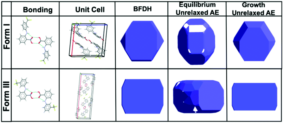 | ||
| Fig. 1 Schematic illustrating the bonding characteristics, unit cell conformation, BFDH and Attachment Energy (AE) predicted morphology of form I and form III.30 | ||
To enable the direct visualisation of the nucleation and subsequent growth of FFA crystals via LCEM, a 50 mM solution of FFA dissolved in ethanol was flowed using a syringe pump through the PEEK tubing of the DENSsolutions Ocean holder. Initial recordings displayed large pre-formed features with a mixture of (but predominantly hexagonal) morphologies. The morphologies observed included hexagonal, truncated triangular and elongated plate-like features (Fig. S1†). These primary observed crystal morphologies are in line with previously reported morphologies of expected polymorphs of FFA which include needles, plates and prisms.31 After irradiating an area for ∼15 seconds, small particles began to develop in void areas. Upon continuous irradiation, these precursor particles began to develop a hexagonal framework and facetted features typical of crystalline materials which resulted in predominantly hexagonal particles, with a minor portion of truncated triangular morphologies (Fig. 2).
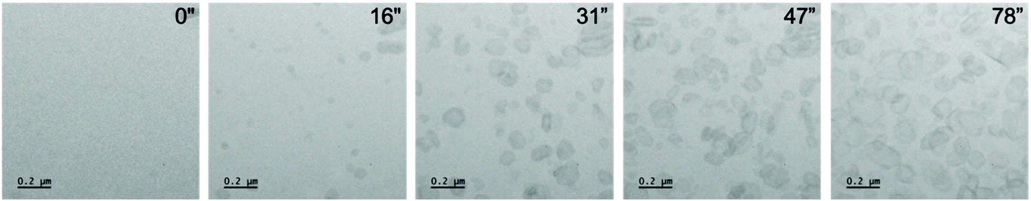 | ||
| Fig. 2 A series of micrographs from Video S7† showing crystals nucleating and growing into hexagonal crystals and related morphologies. At 16′′ nuclei begin to develop a pseudo spherical shape with further faceting observed at 31′′ exhibiting the characteristic hexagonal morphology of form I FFA. Furthermore, the crystals continue to grow under constant illumination saturating the area of view with FFA crystals. Dose rate: 201 e− Å−2 s−1. | ||
The existing hexagonal features that were developed in a previous observation, initially continued to grow (some eventually dislodging) displaying a linear growth trend with continuous electron beam irradiation (Fig. S2†) while in the void areas nuclei began to appear and further develop. The developing nuclei underwent an exponential growth trend exhibiting two distinct growth rates (initially 0.0054 μm s−1 and reducing to 0.0016 μm s−1) suggesting that a multi-step growth trend transpires. As the particles grew under continuous and unchanging illumination dose from the electron beam, charging of the formed particles influenced their movement. During the formation of the hexagonal crystals, the initial nuclei remained static, attached to the window of the liquid cell. It has been reported that the presence of a membrane i.e. silicon nitride window, can significantly decrease the mobility for formed nanoparticles during their observation in LCEM, operating in TEM mode.32 This interaction with the window allowed the particle to grow independently and limit interactions with other particles that could initiate other crystal growth mechanisms such as oriented attachment. After growth into larger crystalline structures, some crystals underwent partial delamination from each other, dislodging from the window and subsequently rotating. This observed rotation of the particles gave insight into the distance between the two windows in the liquid cell which is ultimately influenced by the amount of bowing of the window. The bowing effect is primarily due to the pressure differential between the holder assembled at atmospheric conditions and the vacuum in the TEM column at x10−8 mbar and is further exacerbated by the gaseous products as a result of radiolysis.
One of the difficulties in TEM is the 2D projection of the observed materials. This challenge remains prominent when viewing liquid phase events due to the freedom of movement of the particles in the cell as a result of the influence of fluid movement. This allows alternative projections to be observed of the same particle. In one particular case a hexagonal crystal of FFA is observed initially but after 18 s of continuous observation it becomes clear that there are two superimposed crystals of similar size and morphology (Fig. 3b – red and blue outline). After a further 4 s the blue outlined crystal dislodges and rotates to be positioned sideways i.e. in longitudinal projection (Fig. 3d) revealing elongated hexagonal edges comparable to the predicted morphology of form I FFA. One of the crystals also partially delaminates, however full delamination does not occur as it appears to be attached strongly to another particle. It becomes clear that three crystals were laying where initially only one was assumed with one crystal lying flat (Fig. 3e – red outline) and two crystals now positioned on their side (Fig. 3e – blue and green outline).
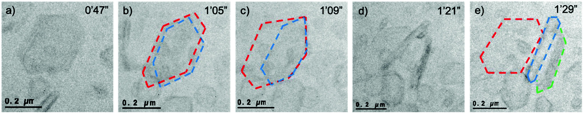 | ||
| Fig. 3 Sequence of images over a period of 42 s where (a) a hexagonal particle is shown in the frame, (b) after 18 s of further illumination two hexagonal crystals are clearly in view, (c) after a further 4 s the crystal outlined in blue dislodges and rotates, (d) after 34 s two crystals have rotated on their side, (e) three crystals are observed whilst it was initially assumed that there was just one (i.e. in Fig. 4a). Frames were taken from Video S8.† For ease, the three crystals have been outlined in red, blue and green, unedited images can be viewed in Fig. S3.† Dose rate: 201 e− Å−2 s−1. | ||
Delamination of complex hydrogen bonded networks such as hydroxide mineral materials has previously been observed with naturally occurring layered bohemite via LCEM.33 Delamination of such hydrated hydroxide materials has been theorised to be caused by a number of factors including radiolysis and also disruption of the hydrogen bonding network when a hole is created in place of a hydrogen atom, thus altering the negative charge and hydrogen bonding capability of the layers. Unlike the work done by Conroy et al.,33 in our work, the layers did not experience dissolution upon delamination as the solvent and the material properties e.g. its stability, as well as the microscope conditions are not comparable.
Regarding the 2D projection challenges of electron microscopy and the added challenge of crystal dynamics, it is paramount to be aware of other available possible morphologies revealed in a polymorphic crystal system such as this. While it is known that the common form of FFA, form III, typically possesses plate and needle-like morphologies, these needle-like features can also appear as a result of rotated side-on structure, such as the hexagonal structure expected of form I.
During observation of continuous illumination of a 50 mM concentration of FFA in ethanol, needle-like structures were observed alongside the hexagonal features. Due to the prevalence of the hexagonal structures and the freedom for the particles to rotate, the movement of the particles is the observed cause of needle-like structures in the experiment. The increased electron density of the needles compared to the hexagonal structures further indicates that these may be longitudinally positioned particles. It was found that the hexagonal particles, influenced by the constant flow of the solution, rotated to reveal a transverse thickness of ca. 26 nm presenting a needle-like structure of the same particle (Fig. S4†). Further observations of similar needle-like features were prevalent throughout the experiment (Fig. 4). The liquid cell design incorporates a sandwich of silicon chips containing silicon nitride windows of 30 nm thickness. With this particular design of liquid cell conformation, the liquid layer is as thin as possible with the absence of a built-in spacer, therefore the liquid layer will be defined by the capillary capability of the prepared silicon windows. It is therefore vital to ensure that the silicon nitride windows are hydrophilic. However, the windows can undergo bowing. In Fig. S4,† a hexagonal crystal is shown to rotate from a projection that suggests it is flat i.e. it has maximum surface interaction with the window, to a projection showing the side of the crystal with needle-like structure, clearly indicated by the high contrast edges of the crystal. This particular hexagonal crystal is ca. 200 nm in width therefore suggesting that the bowing of the windows allowed a liquid layer of at least 200 nm thickness.
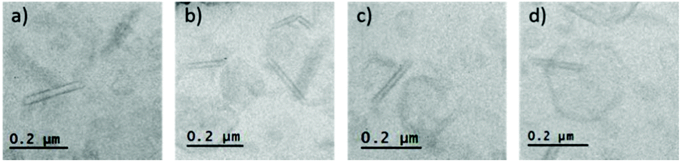 | ||
| Fig. 4 (a)–(d) TEM images of needle-like features observed in the liquid cell during imaging alongside hexagonal features. Dose rate: 201 e− Å−2 s−1. | ||
Due to the direct visualisation of such particle dynamics, it can be confirmed that the observations of hexagonal crystalline structures are analogous with the predicted structures displayed in Fig. 1 for form I.
Nucleation of FFA
It has been reported that the supersaturation of FFA occurs at a concentration of 3 M,34 60 times higher than the concentration used in these experiments. It is not expected that nucleation can occur in such undersaturated conditions at 50 mM where there is no thermodynamic driving force for nucleation to occur. It is worth noting that, in bench-top crystallisation, nucleation is typically initiated by inducing a supersaturated concentration via evaporation, addition of anti-solvent or cooling,35 none of which exist in the described experiments. In Classical Nucleation Theory (CNT) and other non-classical mechanisms of nucleation and growth, the primary stage in crystallisation is nucleation i.e. the formation of nuclei in a supersaturated system.For the formation of organic nanoparticles, studies in literature have suggested that a non-classical nucleation model involving prior existence of critical nuclei known as Pre-Nucleation Clusters (PNC) is more suitable that CNT. The reported PNCs of, for example, calcium carbonate are in the size range of 0.6–2 nm which is beyond the size limit of the current study.36 This rudimentary step in most (if not all) nucleation theories is guided by the free energy of a solution (homogenous and inhomogenous) and how the energy can be minimised with increasing nucleation reaction coordinate.
It is therefore, hypothesised that the energy input from the electron beam into the system is required to contribute to nucleation of the crystalline hexagonal particles from an undersaturated solution. The precise mechanism of how the electron beam is causing nucleation is not fully understood. There are a number of theories reported in literature including; electric fields being created by the incident electron beam, concentrating ions to create local supersaturation in the irradiated area or causing a reduction in the free energy of the solution,37 reactive radicals produced through radiolysis of the solvent reducing the solvated molecules38 and parameters such as the pH changing in the chemical environment due to radiolysis interactions and hence altering the energy barrier required for crystallisation.18
Influence of radiolysis
Radiolysis of water has been outlined in the introduction section, highlighting the highly reactive products that can influence the reaction parameters and hence influence the liquid phase experiment. In these experiments, radiolysis of ethanol not only has the potential to change the native environment of the solvated FFA molecules but can also create nucleation events facilitated by the interaction with the silicon nitride window reducing mobility of the formed species.32 In TEM mode, the electron beam continuously illuminates an area of a certain diameter determined by the probe size.Under the ionising energy of the electron beam, it is expected that radiolysis of the ethanol molecules will occur foremost due to the abundance of the molecules in the solution. This is highlighted by Abellan et al. where for dilute samples <0.1 M, the radiolysis of the solvent i.e. ethanol will dictate the irradiation of the system.39 This is supported by the stability of the aromatic ring components of the FFA molecule which reduces the probability of molecular dissociation due to the pi-orbital electrons. The stability extends to the functional groups attached to the aromatic rings. As such, radiolysis of ethanol will expect to initially dissociate to form a cationic form of ethanol with probability of the electron irradiation also producing radical species:
| CH3CH2OH + e− → CH3CH2OH+ + 2e− |
| CH3CH2OH ⟿ CH3ĊHOH + H˙ |
The probability of these two reactions taking place will depend on the dwelling time of the electrons in the solution and if the electrons will act as single electron entities or radiation. It is also possible that they can occur concurrently.40 Furthermore, the cationic and radical species produced will further react with existing ethanol molecules due to their abundance. It is hypothesised that the interjected electron species can facilitate deprotonation of the carboxylate functional group on the FFA molecules resulting in anions of FFA.41 Due to the effect of immobilisation on charged silicon nitride membranes, as mentioned previously, it is theorised that this can enable immobilisation and hence assembly of the FFA anions leading to crystallisation.
The radical species, particularly the H˙, are highly reactive and will immediately react with other species in the vicinity such as ethanol, oxygen‡ and FFA. These subsequent species also produce additional reactive radical species, molecular products and gas (Table 1).
| Ethanol | |
|---|---|
| Radical species | H˙ |
| HO2˙ | |
| CH3ĊHOH | |
| Molecular species | CH3CHO |
| (CH3CHOH)2 | |
| H2O2 | |
| Gaseous species | H2 |
| O2 |
One of the more important realisations of the work carried out by N. Schneider et al., is the continuous mediation of particular radiolysis products outside the electron beam that continue to react which is not directly observed in the frame of view.18 This effect became apparent when, after observing the main crystal growth events, magnification was reduced to reveal more crystals outside the field of view (remaining within the beam diameter) and also where the beam was not previously irradiating (Fig. S6†). The radiolysis products presumed to interact in this manner are protons and gaseous products, some of which are relevant in the context of the investigations presented here where ethanol is used, although there may be other species that behave in this manner that are not yet identified.
The production of the gaseous radiolysis products manifests additional challenges associated with bubble production which can have disruptive effects such as additional interface reactions, dissolution42 and liquid evacuation. It is obviously apparent when the liquid is removed from the cell due to gas production because the contrast is rapidly improved of the formed molecular crystals. However, what follows is dissolution of the molecular crystal (Fig. 5 and Video S10†). Dissolution was found to occur with continuous irradiation from the electron beam and could be avoided to prevent dissolution by immediately eliminating irradiation by placing the beam blank. This event was recurrent and reproducible with re-entry of the liquid made possible by placing the beam blank, tilting the stage to ±60° and re-engaging liquid flow. The benefit of the formed crystals existing in a gas phase was the ability to acquire Selected Area Electron Diffraction (SAED).§ When the crystals are in liquid phase the thick liquid layer (measured experimentally to be 2–13 μm by top and bottom window z-height comparison) presents challenges associated with scattering of the transmitted beam through the relatively thick material which makes it challenging to be able to obtain certain SAED data (Fig. 6).
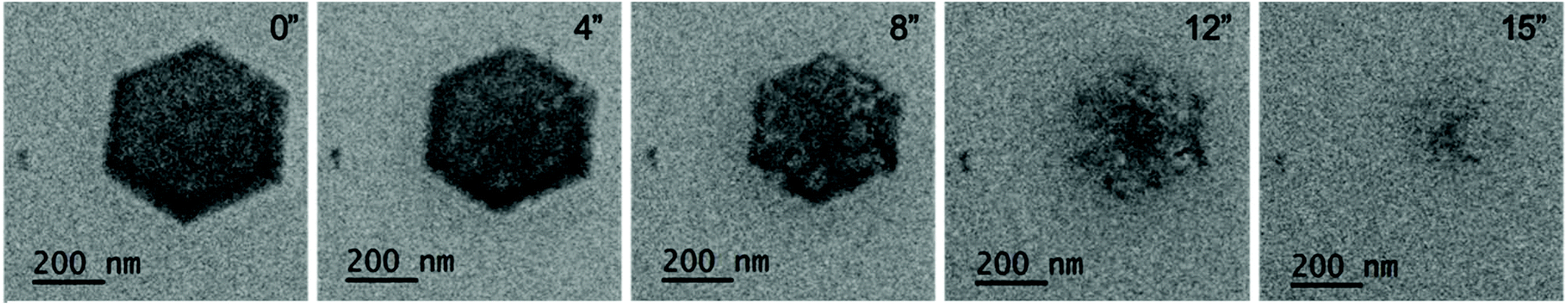 | ||
| Fig. 5 Time series showing the dissolution of a hexagonal FFA crystal initially 553 nm at 0′′, reducing to 508 nm at 4′′ and further reducing in size to 460 nm at 8′′ before the particle has completely dissolved after 15′′. Dose rate 488 e− Å−2 s−1. | ||
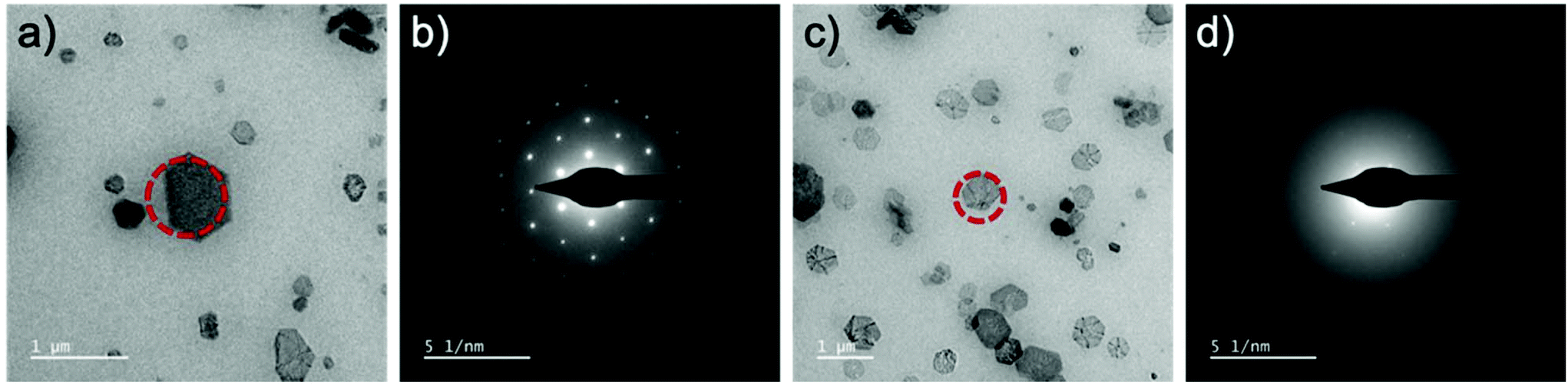 | ||
| Fig. 6 (a) A formed molecular crystal in gaseous phase obtain the clear SAED pattern in (b). (c) A formed molecular crystal formed in liquid and remaining in liquid phase with the corresponding, albeit, diffuse SAED pattern displayed in (d) where only 1st order diffraction spots can be identified. The red dashed circle is used to illustrate where the selected area aperture was positioned to acquire the respective SAED patterns. | ||
The majority of the observed particles are planar in geometry, raising questions regarding the potentially directed and confined growth due to the thinness of the area between the two silicon nitride windows. However, the nuclei developed into hexagonal features during irradiation where the bowing of the windows was developing and thus created a larger liquid space. As mentioned previously, the bowing of the windows during the experiment allowed a gap of at least ca. 200 nm, revealed by the fact that a particle of this size could rotate onto its side. It is, however, important to realise that although the bowing is a result of the pressure differential between the liquid and the vacuum pressure external to the nanocell, the gaseous radiolysis products can contribute to the pressure increase inside the nanocell which can cause the cell to rupture. This becomes more severe and precarious with continuous electron irradiation at extreme dose rates.
It can be assumed that continuous irradiation from the electron beam is required to create the crystals in this particular set of conditions. However, further evaluation is needed to confirm how nucleation and crystallisation is induced by the electron beam and if due to radiolysis, how precisely, the radiolytic products interact with the solvated molecules.
Conclusions
It has been possible for the first time, to visualise nucleation and growth of organic molecules as they develop into solid crystals. Despite the low z-contrast challenges and unavoidable electron beam interactions with the organic solvent and molecular products, hexagonal crystals of FFA were formed and observed using LCEM. These crystals were suggested to be form I, as supported by morphological indicators from the BFDH and AE calculations. Due to exploiting influences from the electron beam, it was possible to alter the local chemistry to obtain the necessary conditions for FFA crystallisation in ethanol at an undersaturated concentration. It is hypothesised that due to radiolysis of the solvent, reactive species are created in the system that result in FFA anions which act as a precursor to crystallisation. However, a thorough study is required to confirm the exact nucleation pathways resulting in organic molecular crystallisation in LCEM.Limited measurements of the crystal growth suggested that a multi-stage growth mechanism occurred with an exponential growth trend evident in measurements of particles from their inception. These initial findings indicate that it is possible to access the initial phases of organic pharmaceutical crystal growth, which was previously unattainable under ambient conditions. The newly developed and ever improving LCEM technique enables observations of the beginnings of crystal nucleation and growth of organic molecules in their native growth solution, exceeding the capability of ex situ characterisation techniques that have been reported thus far. This report details the capability of small organic such as pharmaceutical products to be scrutinised by LCEM. This paves a new investigative method into understanding the influencing factors which result in the culmination of desired polymorphs from crystallisation of pharmaceuticals from solvents. Thus, this will extend to the possibility of visualising and therefore understanding crystallisation processes of similar organic systems.
Materials and methods
Sample preparation
A stock solution of 50 mM FFA (Sigma-Aldrich, 97%) was produced by dissolving in absolute ethanol (Fisher Scientific, HPLC grade). The solution was inverted several times to ensure homogenous dissolution and filtered through a 0.2 μm PES filter (Fisher Scientific), primed with ethanol, to eliminate any dust particles or aggregates. The 50 mM FFA solution was transferred to a 3 ml Luer lock syringe into the PEEK tubing of the liquid cell holder (DENSsolution, Ocean, H-SL-FS-005).Silicon chips preparation
A pair of silicon chips (Nano-Cell, Si3N4 windows 400 μm × 30 μm, no spacer) were selected with orthogonal windows. In three glass vials (Fisher Scientific, borosilicate, 25 mL capacity) solutions of acetone filtered with 0.2 μm PTFE syringe filter (Fisher Scientific, hydrophilic, sterile), ethanol (filtered with 0.2 μm PES syringe filter) and isopropanol (filtered with 0.2 μm PES syringe filter) were placed. The chips were placed in acetone for 4 min (to remove the photoresistant layer), 3 min in ethanol and 3 min in isopropanol. When the pair of chips were ready to be inserted into the liquid cell holder, they were placed on optical lens tissue (PELCO) to dry. The first chip was placed in the bottom of the holder and the second chip was placed upside down (so the windows faced each other). The holder underwent another leak test (pressure reduced to 9 × 10⁻⁶ mbar in under 10 min) to ensure the windows were not damaged in the cleaning process.Liquid cell holder preparation
For the liquid cell experiments, the DENSsolutions Ocean holder (H-SL-FS-005) was prepared using the following method. Firstly, each line of the PEEK tubing (inlet and outlet) was flushed with 6 mL (2 × 3 ml syringes) of ethanol and 6 mL (2 × 3 ml syringes) of water using a syringe pump flowing at 400 μl min−1 into a waste container. The holder tip components including the screws, O-rings, tip lid and bottom and PEEK tubing connections were placed in a vial filled with ethanol and placed in an ultrasonic bath for 5 min to completely remove any contaminants. The holder components were placed on lint-free lens tissue to dry. The holder was assembled with blank silicon chips (windowless) to test the vacuum leak tightness of the O-rings before placing the silicon nitride windows intended for the experiments. The assembled holder was placed in a vacuum pump (Pfeiffer vacuum, HiCUBE ECO), once the vacuum reduced to 9 × 10⁻⁶ mbar in under 10 min the holder was deemed leak tight and safe to insert into the TEM. The holder was then plasma cleaned for 15 min with a combination of H2 and O2 to remove any carbon contamination that could affect the vacuum and outgassing of contaminants in the TEM column.Liquid cell electron microscopy
Alignments for the TEM were completed with a gold standard sample on a single tilt holder to achieve optimal resolution, these include refining the image corrector and setting the monochromator to achieve controllable low dose conditions. Once the alignments were complete, the Ocean holder was inserted into the FEI Titan Themis3 TEM undergoing a 10 min pre-pump before fully inserting the holder into the column. The PEEK tubing was connected to a solution of filtered ethanol in a 3 mL syringe fitted to a syringe pump. Ethanol was flowed through the holder at a rate of 5 μL min−1 for 1 h to ensure total immersion of the solution between the Si3N4 windows. The windows were viewed in ethanol only conditions to map any defects and ensure the cleaning procedure was effective. Finally, a solution of FFA was flowed through the holder at a rate of 5 μL min−1 for 1 h prior to experimental imaging.Dose measurements
Dose measurements were acquired by taking the reading from the incident beam hitting the flu-screen in units of e− Å−2. This was then converted to dose rate by taking into consideration the exposure time of acquisition, converting the parameter into e− Å−2 s−1.Crystal calculations
All molecular images, bonding motifs and crystal habit predictions using BFDH were calculated using the Mercury software package. The crystal structures used in these calculations were obtained from The Cambridge Crystallographic Data Centre. The morphologies were also estimated using the attachment energy model.28Micrograph processing
Micrographs were extracted from Video S5† and those used in Fig. 3 and Fig. S1† were processed by applying a bandpass filter using the Gatan Microscopy Suite (GMS3) programme.Conflicts of interest
There are no conflicts to declare.Acknowledgements
This work was supported by MagnaPharm a European Union Horizon 2020 Research and Innovation programme (grant agreement number 736899). J.C. would like to acknowledge European Microscopy Society (EMS) and the Royal Microscopical Society (RMS) and Materials Division of Royal Society of Chemistry (RSC) for scholarships to present this work at the International Microscopy Congress (IMC) in Sydney, Australia, Microscopy and Microscience Congress (MMC) in Manchester, UK and also Microscopy & Microanalysis (M&M) in Portland, USA. V.H. would like to acknowledge the Bristol Centre for Functional NanoMaterials funded by the Engineering and Physical Sciences Research Council (EPRSC) UK (grants EP/G036780/1 and EP/L015544). The authors would like to acknowledge Sarah L. Price and Rui Guo of University College London (UCL) for productive conversations regarding polymorphism and crystal growth.References
- Y. Guo, G. Yu and Y. Liu, Adv. Mater., 2010, 22, 4427–4447 CrossRef CAS PubMed
.
- R. J. Wu, K. X. Zhou, H. Yang, G. Q. Song, Y. H. Li, J. X. Fu, X. Zhang, S. J. Yu, L. Z. Wang, L. X. Xiong and C. W. Niu, Eur. J. Med. Chem., 2019, 167, 472–484 CrossRef CAS PubMed
- M. W. Walter, Nat. Prod. Rep., 2002, 19, 278–291 RSC
- N. Variankaval, A. S. Cote and M. F. Doherty, AIChE J., 2008, 54, 1682–1688 CrossRef CAS
- Y. Tsarfati, S. Rosenne, H. Weissman, L. J. Shimon, D. Gur, B. A. Palmer and B. Rybtchinski, ACS Cent. Sci., 2018, 4, 1031–1036 CrossRef CAS PubMed
- J. Hermannsdörfer and N. de Jonge, J. Visualized Exp., 2017, 120, e54943 Search PubMed
- J. Yang, C. M. Andrei, Y. Chan, B. L. Mehdi, N. D. Browning, G. A. Botton and L. Soleymani, Langmuir, 2019, 35, 862–869 CrossRef CAS PubMed
- B. L. Mehdi, J. Qian, E. Nasybulin, C. Park, D. A. Welch, R. Faller, H. Mehta, W. A. Henderson, W. Xu, C. M. Wang and J. E. Evans, Nano Lett., 2015, 15, 2168–2173 CrossRef CAS PubMed
- H. Zheng, R. K. Smith, Y. W. Jun, C. Kisielowski, U. Dahmen and A. P. Alivisatos, Science, 2009, 324, 1309–1312 CrossRef CAS PubMed
- J. E. Evans, K. L. Jungjohann, N. D. Browning and I. Arslan, Nano Lett., 2011, 11, 2809–2813 CrossRef CAS PubMed
- M. H. Nielsen, A. Shaul and J. J. De Yoreo, Science, 2014, 345, 1158–1162 CrossRef CAS PubMed
- X. Wang, J. Yang, C. M. Andrei, L. Soleymani and K. Grandfield, Commun. Chem., 2018, 1(1), 80 CrossRef
- D. Li, M. H. Nielsen, J. R. Lee, C. Frandsen, J. F. Banfield and J. J. De Yoreo, Science, 2012, 336(6084), 1014–1018 CrossRef CAS PubMed
- D. Erdemir, A. Y. Lee and A. S. Myerson, Acc. Chem. Res., 2009, 42, 621–629 CrossRef CAS PubMed
- T. Yamazaki, Y. Kimura, P. G. Vekilov, E. Furukawa, M. Shirai, H. Matsumoto, A. E. Van Driessche and K. Tsukamoto, Proc. Natl. Acad. Sci. U. S. A., 2017, 114, 2154–2159 CrossRef CAS PubMed
- A. Ianiro, H. Wu, M. M. Van Rijt, M. P. Vena, A. D. Keizer, A. C. Esteves, R. Tuinier, H. Friedrich, N. A. Sommerdijk and J. P. Patterson, Nat. Chem., 2019, 11, 320–328 CrossRef CAS PubMed
- S. M. Rehn and M. R. Jones, ACS Energy Lett., 2018, 3, 1269–1278 CrossRef CAS
- N. M. Schneider, M. M. Norton, B. J. Mendel, J. M. Grogan, F. M. Ross and H. H. Bau, J. Phys. Chem. C, 2014, 118, 22373–22382 CrossRef CAS
- S. Le Caër, Water, 2011, 3, 235–253 CrossRef
-
Liquid Cell Electron Microscopy, ed. F. M. Ross, Cambridge University Press, Cambridge, 2016 Search PubMed
- J. Bauer, S. Spanton, R. Henry, J. Quick, W. Dziki, W. Porter and J. Morris, Pharm. Res., 2001, 18, 859–866 CrossRef CAS PubMed
- E. H. Lee, Asian J. Pharm. Sci., 2014, 9, 163–175 CrossRef
- P. G. Vekilov, Cryst. Growth Des., 2010, 10, 5007–5019 CrossRef CAS PubMed
- W. Sun and G. Ceder, CrystEngComm, 2017, 19, 4576–4585 RSC
- C. V. Winder, J. Wax, B. Serrano, E. M. Jones and M. L. McPhee, Off. J. Am. Coll. Rheumatol., 1963, 6, 36–47 CAS
- E. H. Lee and S. R. Byrn, J. Pharm. Sci., 2010, 99, 4013–4022 CrossRef CAS PubMed
- R. Docherty, G. Clydesdale, K. J. Roberts and P. Bennema, J. Phys. D: Appl. Phys., 1991, 24, 89 CrossRef CAS
- D. S. Coombes, C. R. A. Catlow, J. D. Gale, A. L. Rohl and S. L. Price, Cryst. Growth Des., 2005, 5, 879–885 CrossRef CAS
- E. H. Lee, S. X. Boerrigter, A. C. Rumondor, S. P. Chamarthy and S. R. Byrn, Cryst. Growth Des., 2008, 8, 91–97 CrossRef CAS
- S. P. Delaney, T. M. Smith and T. M. Korter, J. Mol. Struct., 2014, 1078, 83–89 CrossRef CAS
- V. López-Mejías, J. W. Kampf and A. J. Matzger, J. Am. Chem. Soc., 2012, 134, 9872–9875 CrossRef PubMed
- T. J. Woehl and T. Prozorov, J. Phys. Chem. C, 2015, 119, 21261–21269 CrossRef CAS
- M. Conroy, J. A. Soltis, R. S. Wittman, F. N. Smith, S. Chatterjee, X. Zhang, E. S. Ilton and E. C. Buck, Sci. Rep., 2017, 7, 13274 CrossRef PubMed
- S. Alshehri and F. Shakeel, J. Mol. Liq., 2017, 240, 447–453 CrossRef CAS
-
H. H. Tung, E. L. Paul, M. Midler and J. A. McCauley, Crystallization of Organic Compounds: An Industrial Perspective, John Wiley & Sons, 2019 Search PubMed
- E. M. Pouget, P. H. Bomans, J. A. Goos, P. M. Frederik, G. de With and N. A. Sommerdijk, Science, 2009, 323, 1455–1458 CrossRef CAS PubMed
- N. Jiang, Ultramicroscopy, 2017, 179, 81–83 CrossRef CAS PubMed
- T. J. Woehl, J. E. Evans, I. Arslan, W. D. Ristenpart and N. D. Browning, ACS Nano, 2012, 10, 8599–8610 CrossRef PubMed
- T. J. Woehl and P. Abellan, J. Microsc., 2017, 135–147 CrossRef CAS PubMed
-
J. W. T. Spinks and R. J. Woods, An introduction to radiation chemistry, John Wiley & Sons, London, 1964 Search PubMed
-
J. Clayden, N. Greeves and S. Warren, Organic Chemistry, Oxford University Press, 2012 Search PubMed
- J. M. Grogan, N. M. Schneider, F. M. Ross and H. H. Bau, Nano Lett., 2013, 14, 359–364 CrossRef PubMed
Footnotes |
| † Electronic supplementary information (ESI) available. See DOI: 10.1039/c9nr08126g |
| ‡ These experiments are carried out using hydrated ethanol. Anhydrous ethanol (aka dry ethanol) will not likely have an oxygen component and will limit the production of dihydrogen peroxide, HO2˙, CH3C(O2˙)HOH and acetaldehyde species. |
| § Due to the outlined difficulties of rapid dissolution of the crystals in the gaseous phase, more work is being carried out to rapidly acquire electron diffraction on a single crystal for certain quantification of crystal spacing parameters. This will provide more evidence of polymorph identification complementary to morphological identification. |
| This journal is © The Royal Society of Chemistry 2020 |