Cobalt-doping SnS2 nanosheets towards high-performance anodes for sodium ion batteries†
Liqin
Wang
,
Quanqing
Zhao
,
Zhitao
Wang
,
Yujun
Wu
,
Xilan
Ma
,
Youqi
Zhu
* and
Chuanbao
Cao
 *
*
Research Center of Materials Science, Beijing Key Laboratory of Construction Tailorable Advanced Functional Materials and Green Applications, Beijing Institute of Technology, Beijing 100081, China. E-mail: yqzhu@bit.edu.cn; cbcao@bit.edu.cn
First published on 18th November 2019
Abstract
Layered SnS2 is considered as a promising anode candidate for sodium-ion batteries yet suffers from low initial coulombic efficiency, limited specific capacity and rate capability. Herein, we report a cobalt metal cation doping strategy to enhance the electrochemical performance of a SnS2 nanosheet array anode through a facile hydrothermal method. Benefitting from this special structure and heteroatom-doping effect, this anode material displays a high initial coulombic efficiency of 57.4%, a superior discharge specific capacity as high as 1288 mA h g−1 at 0.2 A g−1 after 100 cycles and outstanding long-term cycling stability with a reversible capacity of 800.4 mA h g−1 even at 2 A g−1. These excellent performances could be ascribed to the Co-doping effect that can increase the interlayer spacing, produce rich defects, regulate the electronic environment and improve conductivity. Besides, a carbon cloth substrate can maintain the integrity of the electrode material framework and buffer its volume variation, thus boosting intrinsic dynamic properties and enhancing sodium storage performance.
1. Introduction
Layered tin disulfide (SnS2) has been proposed as one of the most hopeful anode candidates for SIBs because of its high theoretical capacity (1136 mA h g−1) resulting from conversion and alloying reactions (SnS2 + 4Na → Sn + 2Na2S; Sn + 3.75Na ↔ Na3.75Sn).1 Furthermore, layered SnS2 can be exfoliated to a single- or few-layered sheet to generate distinctive physical and chemical properties and afford an open framework to facilitate Na-ion transportation and electrolyte flooding.2–4 Additionally, the large interlayer spacing (0.59 nm) and stable CdI2-type structure with three stacked atom (S–Sn–S) layers united by van der Waals forces of SnS2 make it a suitable candidate for hosting the Na+ intercalation.5,6 However, like other sulfide material electrodes, the SnS2 anode is also subjected to a large volume variation (520% deriving from Sn to Na3.75Sn) and poor electrical conductivity, which could result in severe pulverization and aggregation and thus unsatisfactory electrochemical performances.7 Various schemes have been implemented to overcome the aforementioned challenges, such as constructing special morphologies (porous or hollow structure), heteroatom doping and introducing conductive substrates.8–11 Hybridizing SnS2 with a conductive matrix is an effective approach to buffer the volume variation and enhance the electronic conductivity.12,13 For example, the capacity of SnS2 nanosheets with N-doped graphene (SnS2/NGS) reaches 453 mA h g−1 at 0.1 A g−1.14 The ultrasmall SnS2 nanoplate restacked on graphene with a three-dimensional (3D) network exhibits a discharge capacity of 650 mA h g−1 at 0.2 A g−1.15 The reversible capacity of SnS2 nanosheet arrays is up to 631 mA h g−1 at 0.05 A g−1.16 Therefore, the structural stability and synergetic effects between SnS2 and graphene lead to significantly improved sodium storage properties.Metal compounds (like Cu, Fe, Ni, and Co-based) can also serve as a type of anode material for SIBs due to their conversion/recombination mechanism.17–19 It is reported that introducing metallic Fe or Co cations can not only improve catalytic activity but also endow the compounds with a flexible structure to withstand the severe volume change of Sn and increase conductivity, resulting in improved initial coulombic efficiency (ICE) and cycling stability.19–21 The specific capacity of Co-doped FeS2 nanospheres is stabilized at 220 mA h g−1 after 5000 cycles and 172 mA h g−1 even at 20 A g−1 and still maintains a layered structure in the following cycles.22 Therefore, the construction of Co-doped SnS2 nanosheets grown on flexible carbon cloth (CC) will combine the virtues of different strategies and is expected as a novel approach for further enhancing the electrochemical properties of Sn-based anode materials.
According to our previous paper,23 the SnS2/CC anode reveals a specific capacity of 1039.9 mA h g−1 with a lower ICE of 32.8% at 0.2 A g−1. To further improve the reversible capacity and ICE, the aligned SnS2 nanosheet arrays uniformly grown on the CC substrate with different doping contents of metal Co as an advanced anode for high-powered SIBs have been prepared. In previous literature studies, although metal atom (e.g., Ag, Zn, Mg, Pt, and Mo) doped SnS2 samples have been applied to dye-sensitized solar cells,24 electromagnetic fields,25 ferromagnetic spin-order,26 electrocatalytic hydrogen evolution reactions27 and lithium ion batteries,28 respectively, there is no paper reported on sodium storage fields. The Co-doped SnS2 sample as an anode material is first reported in this paper except for Li–S batteries.29 Moreover, the phenomenon of metal Co doping, which makes solid electrolyte interphases (SEI film) become thinner and more homogeneous on the surface of the electrode material compared to pure SnS2, is first discovered. Based on several advantages of enlarged interlayer spacing, rich lattice defects, good conductivity of ionic crystals and even SEI films, when the doping content of Co reaches 4% (4Co-SnS2/CC), the electrode shows a higher capacity of 1288 mA h g−1 with an enhanced ICE of 57.4% at 0.2 A g−1 and an excellent fast charge/discharge behavior of 800.4 mA h g−1 at 2 A g−1 with superior rate capability. The appropriate introduction of metal Co atoms into the interlayer of SnS2 nanosheets can be used as a significant atomic-level lattice engineering technology, indicating that transition metal atoms (e.g. Ag, Au, Co, Cu, and Fe) can also intercalate into the interlayer of other 2D layered structure materials to change the formation of SEI films and enhance sodium storage performance.
2. Results and discussion
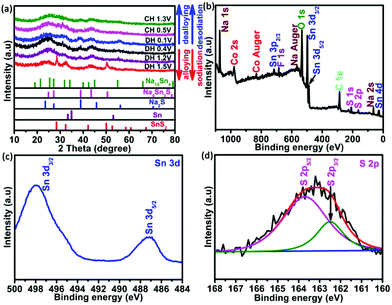
The typical synthesis principles of uniformly distributed Co-SnS2 nanosheets vertically growing on the CC substrate are demonstrated in Fig. S1.† The oxygen-contained functional groups on the CC surface from H2O2 treatment are beneficial for absorbing metal ions and tightly immobilizing SnS2 nanosheets. The crystal structures of 4Co-SnS2/CC, SnS2/CC and CoS2 were detected by X-ray diffraction (XRD), as shown in Fig. 1 and Fig. S2.† Compared to the SnS2/CC sample, the 4Co-SnS2/CC sample has no impurity phase apart from SnS2, where all the diffraction peaks can be assigned to the hexagonal SnS2 crystal phase with a space group of PPm1 (164) (PDF#23-0677) (in Fig. 1a). No diffraction peak of the CoS2 phase is observed from the Co-doping SnS2 sample, illustrating that a low molar ratio of Co can be doped into the SnS2 crystal lattice; this result is similar to other metal doping in materials.28 The peak at 15.02° with a lattice plane of (001) has slightly shifted to a low angle, indicating an increased interlayer distance according to Bragg's formula (d = 0.5λ/sin(θ)), and the d-spacing ranges from 5.98 Å to 6.02 Å after calculation by least-squares fitting with 2θ and (h k l). Moreover, the metal Co dopant would partially substitute Sn sites in the SnS2 crystalline structure, bringing about the increment of stacking fault energy, enhancing the densities of nucleation centers to reduce the grain size, and thus (001), (101), (102) and (111) peaks becoming weaker and broader.28,30,31 The chemical composition and valence states of the 4Co-SnS2/CC sample were studied through X-ray photoelectron spectroscopy (XPS). In Fig. 1b, no impurity signal except from the Sn, Co, S, C and O elements can be observed in the 4Co-SnS2/CC composite, indicating that the metal Co cation has been successfully introduced into SnS2. In the Sn 3d spectra (Fig. 1c), the peaks located at 486.9 and 495.3 eV for 4Co-SnS2/CC can be summed up in Sn 3d5/2 and Sn 3d3/2, respectively, which correspond to tetravalent Sn4+.31,32 All the present peaks have almost no deviation compared to the Sn 3d spectra of the SnS2/CC sample. For S 2p spectra (Fig. 1d), there are two peaks at 161.3 and 162.5 eV in the Co-SnS2/CC composite, which can be ascribed to S 2p3/2 and S 2p5/2 of S2−,33 and all peaks slightly shift to low binding energy compared to S 2p of SnS2/CC. Fig. S3a† displays the typical high-resolution spectrum of Co 2p for 4Co-SnS2/CC, the curve fitting of Co 2p3/2 corresponds to Co2+ (776.2 eV) and Co3+ (779.9 eV), and the other is Co 2p1/2 for Co2+ (794.4 eV) and Co3+ (798.6 eV) along with five satellite peaks.34,35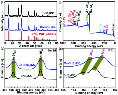 | ||
| Fig. 1 (a) XRD patterns of 4Co-SnS2/CC and SnS2/CC. (b) Survey XPS spectrum of 4Co-SnS2/CC. High-resolution Sn 3d (b) and (c) S 2p spectra. | ||
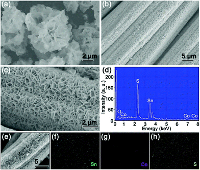
The morphologies and structures of the as-obtained 4Co-SnS2/CC material are shown in Fig. 2. In Fig. 2a, the 4Co-SnS2 counterpart without the CC substrate displays a nanoflower-like morphology with slight agglomeration and an average diameter size of 3.5 μm. By contrast, the 4Co-SnS2 nanosheets grown on the CC substrate exhibit a distinct vertical and symmetric array morphology without agglomeration (in Fig. 2b and c) and similar to SnS2/CC (in Fig. S5†). Meanwhile, the pure CoS2 sphere with a diameter of 2 μm is displayed in Fig. S4.† Hence, the CC can effectively promote the formation of nanosheets. According to the EDS analysis (Fig. 2d), there are only five elements of Sn, S, Co, C and O without any impurity and the molecular formula is found to be Sn0.89Co0.11S2, which is nearly consistent with the actual theoretical ratio of SnS2. From the checked region of the 4Co-SnS2/CC SEM image (Fig. 2e), it is found that the Sn, Co and S elements are uniformly dispersed on the CC substrate (Fig. 2f–h).
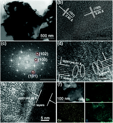
The microstructures of 4Co-SnS2 peeled from the CC substrate were further investigated by TEM analysis, as displayed in Fig. 3. Fig. 3a clearly shows a sheet-like morphology of 4Co-SnS2. In Fig. 3b, the HRTEM image precisely displays the obvious regular lattice fringes with interlayer distances of 2.83 and 3.26 Å related to the typical 2D intercrystalline (101) and (100) facets of SnS2, consistent with the Fast Fourier Transform (FFT) pattern in Fig. 3c. The 4Co-SnS2 nanosheets have a larger interlayer spacing of 6.01 Å (Fig. 3d) than SnS2 (5.98 Å in Fig. 3e). The interlayer spacing extension should result from Co doping in the SnS2 crystal lattice. Additionally, compared to the intact fringes of pure SnS2, 4Co-SnS2 presents some rich defects and discrete lattice fringes, indicating that Sn is replaced by the Co atom. Therefore, the heteroatom Co doping can enlarge the lattice spacing and produce defects in the SnS2 nanosheet, which is consistent with XRD analysis (Fig. 1a). This may be attributed to the fact that the radius of Co is smaller than that of Sn and the metal Co atoms are intercalated into the interlayer of layered nanosheets to disorder the stacking of the SnS2 layer. Various chemical valences (Co2+/Co3+vs. Sn4+), leading to vacant sites from the absence of bonding electrons, would reduce the stability of the structure and mechanical strength, therefore enlarging interlayer space. Besides, alkali metal atoms and transition metal atoms (e.g. Ag, Au, Co, Cu, and Fe) can also intercalate into the 2D layered structure materials to enlarge the interlayer space without destroying the host lattice.36,37 It has been reported that defects or disorder structures can facilitate more sodium ion insertion and increase the conductivity of ionic crystals and active centres.38,39 So the increased lattice spacing and enriched defects of 4Co-SnS2 have a favorable influence on the improvement of sodium storage capacity. The STEM image and EDX elemental mapping (Fig. 3f) show that Co has been successfully doped into SnS2 nanosheets with homogeneous distribution. EDS (Fig. S6†) shows that the analogous molecular formula of Sn0.9Co0.1S2 is almost consistent with the result from Fig. 2d.
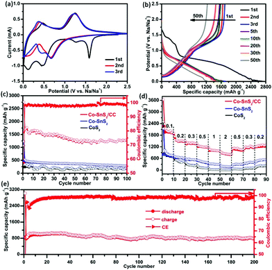
To verify the electronic application of such an integrative structure, the as-prepared 4Co-SnS2/CC was immediately evaluated as an additive-free anode for SIBs. The first three CV profiles of 4Co-SnS2/CC were implemented to investigate the electrochemistry and are shown in Fig. 4a. Compared to our previous work,23 the variation tendency of 4Co-SnS2/CC CV curves is similar to that of SnS2/CC. There exist some analogical peaks at a similar position involving reduction and oxidation peaks. At the first cathodic scan, the peak at 1.58 V for 4Co-SnS2/CC represents the intercalation of the Na-ion into the SnS2 layers forming NaxSnS2 without structure decomposition (xNa+ + SnS2 + xe− → NaxSnS2).32,40 However, this peak suddenly disappeared in the subsequent cycles, indicative of the irreversible capacity decrease to some extent.30,41 The peak at 1.27 V can be attributed to the decomposition of NaxSnS2 into metal Sn and Na2S (NaxSnS2 + (4 − x) Na+ → Sn + 2Na2S). Additionally, the peak at 0.46 V can be ascribed to the Na–Sn alloying reaction between Na+ and metal Sn (Sn + 3.75Na+ + 3.75e− → Na3.75Sn), followed by the formation of SEI films at the peak of 0.11 V. During the first anodic sweep, there are two broad peaks at 0.46 and 1.24 V, standing for the dealloying reaction of NaxSn and the oxidation reaction from metallic Sn to SnS2 during the desodiation process.42 The CV curves almost overlap after the sequential loops, suggesting that the Na-ion insertion/extraction process in the electrode is fairly reversible. However the enclosed areas become smaller than that of the first cycle, indicating that the capacity fading takes place in the sequential loops. However, the reduction peaks have distinctly shifted in the second cycle compared to those in the first cycle, and these results can be attributed to the common electrode polarization observed in other materials.43,44 Similarly, the reduction peaks at 0.67 and 0.43 V are observed in the sodiation process, and the oxidation peaks at 0.37 and 1.24 V are related to the same desodiation process like in the first cycle reaction. Fig. 4b shows the corresponding galvanostatic charge/discharge voltage profiles of the 4Co-SnS2/CC anode at 0.2 A g−1. There are four voltage platforms observed in the first discharge cycle, which are in good accordance with the CV profiles. The platform at 1.43 V corresponds to the Na+ insertion into the SnS2 layers generating NaxSnS2, and the short platform at 1.24 V is related to the conversion reaction from NaxSnS2 to metal Sn and Na2S. Meanwhile, the broad slope at 0.74 V and the narrow platform at 0.09 V are ascribed to the Na–Sn alloying reaction and the SEI generation.45 Of course, there exist two slopes in the first charge cycle, signifying the NaxSn dealloying reaction and the oxidation reaction. After the second cycle, the discharge and charge platforms become narrow and the platforms at 1.43 and 1.24 V have disappeared, indicating the capacity reduction. The existing two slight slopes with discharge voltages of 0.74–0.86 and 0.05–0.08 V exhibit the alloying reaction and repeated SEI formation process. The charge slopes at 0.16–0.28 and 1.02–1.62 V denote the dealloying processes, and these characteristics would continue in the subsequent loops. 4Co-SnS2/CC was directly used as an electrode without any binder and conductive agent, the specific capacity was measured based on the 4Co-SnS2 mass, and the results are shown in Fig. 4c. The 4Co-SnS2/CC anode delivers the initial high discharge/charge capacities of 2757.6/1583.5 mA h g−1 with an ICE of 57.4%, which is higher than that of SnS2/CC (∼32.8% in Ref. 23). The improved ICE of 4Co-SnS2/CC can be attributed to the formative thin and homogeneous SEI film on the SnS2 nanosheet surface, profiting from heteroatom Co doping (Fig. 7c and d), which is basically similar to the reaction of Li2O ↔ Li2O2/LiO2.46 Besides, the larger interlayer spacing can contribute to improving the reversible insertion efficiency of Na+ and infiltration of electrolytes. After the second cycle, the capacity gradually stabilizes and CE rapidly increases to 98%. The specific discharge capacity can reach up to 1288 mA h g−1 (the practical capacity is about 1132 mA h g−1 removing from the contribution of CC, which is equivalent to the theoretical capacity of 1136 mA h g−1 for layered SnS2) after 100 cycles with 98.3% CE, which is superior to that of pure SnS2/CC (∼1039.9 mA h g−1) and other Co doping contents of SnS2/CC (1Co-SnS2/CC ∼1061.3, 2Co-SnS2/CC ∼1098.4, 3Co-SnS2/CC ∼1223.1, 5Co-SnS2/CC ∼1147.1 and 6Co-SnS2/CC ∼1001.3 mA h g−1 and shown in Fig. S7†), 4Co-SnS2 without the CC substrate (∼283 mA h g−1), and CoS2 (∼179.3 mA h g−1). The specific capacities of Co-SnS2/CC electrodes gradually increase with the doping amounts of the Co element from 1% to 4%, and it can be attributed to the Co-ion evenly dispersed in SnS2 nanosheets, leading to the significant hybrid effects and synergistic effect. However, the capacities gradually decay when the Co contents are higher than 4%, which may be caused by the excessive metallics accumulated on the surface of nanosheets, hampering the transformation of electrons/ions and reducing the sodium storage capacity. The rate capability of 4Co-SnS2/CC was examined in different current density ranges of 0.1–2 A g−1, as shown in Fig. 4d. The capacity gradually decreases with the increasing current densities. The average discharge/charge capacities are 2037.8/1962.6 mA h g−1, 1501.8/1478.2 mA h g−1, 1376.6/1356.6 mA h g−1, 1189.3/1174.3 mA h g−1, 1002.6/995.5 mA h g−1, and 823.2/809.3 mA h g−1 at 0.1, 0.2, 0.3, 0.5, 1, and 2 A g−1, respectively. With the current density back to 0.2 A g−1 again, the capacities can return to 1248.9/1202.1 mA h g−1, indicative of good resilience ability due to its robust structure. Obviously, the rate capability is much higher than that of the SnS2/CC, 4Co-SnS2 and CoS2 anodes. Moreover, the fast charging–discharging performance of 4Co-SnS2/CC has been tested as shown in Fig. 4e. The reversible capacity gradually declines and finally stabilizes at 800.4 mA h g−1 with 98.7% CE at 2 A g−1 upon 200 cycles, which is much higher than that of SnS2/CC (∼673.4 mA h g−1). Therefore, the metal Co doping is favorable for sodiation and desodiation processes. Heteroatom Co has intercalated into the interlayer of layered SnS2 nanosheets to enlarge d-spacing, facilitates the intercalation and diffusion of Na-ions and improves the diffusion kinetics. The produced vacant sites and lattice defects severed as active sites to heighten sodium storage capacity. Besides, it can improve the conductivity of ionic crystals and reduce the resistance of ions corresponding to the Co role in Co-doped FeOF.47 Compared to other SnS2-based materials reported in literature studies, the capacity values of the 4Co-SnS2/CC anode are fairly high and the contrast capacities are listed in Table S1.†
To verify this excellent performance, the analysis of the crystal structure on the 4Co-SnS2/CC electrode was implemented by XRD in different charge and discharge states and is shown in Fig. 5. Compared to the pristine material in Fig. 2, the primary peaks of SnS2 at 28.2°, 32.2°, 42°, 49.9° and 52° and intermediate products of Na4Sn3S8 at 24.8°, 38.8°, 43.4° and 50.5° can be observed in the discharge stage at 1.5 V. As the discharge continues, the SnS2 peaks become weak and the Sn and Na2S phases begin to appear, indicating that the nanosized Sn particles first nucleate from the conversion reaction of Na and SnS2 corresponding to the 1.2 V discharge plateau as reported in the literature.48 When discharged to 0.4 V, the Na-ion and metallic Sn are converted into Na–Sn alloys of Na15Sn4. Finally, the diffraction peaks of Na–Sn alloys at 19.0° and 31.9° are further enhanced with crystalline Sn diffraction peaks disappearing at the discharge stage of 0.1 V.49 After charging the electrode to 0.4 V, the SnS2 phase begins to reconstruct from the oxidation reaction of Sn. However charging to 1.3 V, there are no explicit XRD peaks from the transformation of the Sn phase to poor crystallinity or amorphous components. XPS technology was further implemented in the charge state after 100 cycles to understand the involved chemical state changes in the 4Co-SnS2/CC anode. Fig. 5b displays the survey spectrum of 4Co-SnS2/CC, including the Sn, S, Co, C, Na, O and F elements. Clearly, Na, O and F elements are dating from the electrolyte. The targeted peaks of Sn and S elements (Fig. 5c and d) are fitted by the Gaussian fitting method, which are denoted as Sn4+ (487.2 and 498 eV) and S2− (162.3 and 163.7 eV). Similarly, the Co valences exhibit no distinct change (in Fig. S3b†), but all the peak positions of Sn, S and Co elements shift to the high binding energy compared to the pristine sample (Fig. 3b, c and Fig. S3a†). These results further illustrate that the metal Co cation has been successfully introduced into the SnS2/CC composite, and Co doping can enhance binding energy to improve the internal kinetics of the electrode.
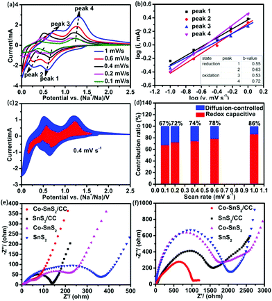
To further investigate the electrochemical reaction mechanism of 4Co-SnS2/CC, the CV measurement at different scan rates from 0.1 to 1 mV s−1 and the EIS test in the fresh state and after 100 cycles were implemented as shown in Fig. 6. Fig. 6a shows the CV curves at different scan rates with a similar shape at each scan rate. According to the results from the stepwise sodiation/desodiation reaction, the total charge storage principles can be classified as three cases: the diffusion-controlled faradaic contribution from the alloying/dealloying reaction, the pseudocapacitance effect from charge transfer with surface atoms, and non-faradaic contribution from the double layer capacitor.50,51
The practical reaction can be calculated using eqn (1) and (2):
| i = a*vb, | (1) |
log![[thin space (1/6-em)]](https://www.rsc.org/images/entities/char_2009.gif) i = b*log i = b*log![[thin space (1/6-em)]](https://www.rsc.org/images/entities/char_2009.gif) v + log v + log![[thin space (1/6-em)]](https://www.rsc.org/images/entities/char_2009.gif) a, a, | (2) |
![[thin space (1/6-em)]](https://www.rsc.org/images/entities/char_2009.gif) v vs. log
v vs. log![[thin space (1/6-em)]](https://www.rsc.org/images/entities/char_2009.gif) i plots. When the b-value approaches 1.0, it denotes the capacitive process, whereas the b-value of 0.5 displays a diffusion-controlled feature. Fig. 6b shows the plots of log
i plots. When the b-value approaches 1.0, it denotes the capacitive process, whereas the b-value of 0.5 displays a diffusion-controlled feature. Fig. 6b shows the plots of log![[thin space (1/6-em)]](https://www.rsc.org/images/entities/char_2009.gif) i vs. log
i vs. log![[thin space (1/6-em)]](https://www.rsc.org/images/entities/char_2009.gif) v at different oxidation/reduction peaks. The b-values of reduction peaks (peak 1 and 2) and oxidation peak 3 are nearly 0.5 and that of peak 4 is 0.72, indicating that the kinetics are controlled by the diffusion-controlled and capacitive process, respectively. Fig. 6c shows the typical profile of the redox capacitive (red region) in comparison with the total capacitive at a scan rate of 0.4 mV s−1. The contribution ratio of Na-ion capacitance can be quantified by assigning the i parallel potential V to redox capacitive effects (k1*v) and diffusion-controlled reactions (k2*v1/2), according to eqn (3),52
v at different oxidation/reduction peaks. The b-values of reduction peaks (peak 1 and 2) and oxidation peak 3 are nearly 0.5 and that of peak 4 is 0.72, indicating that the kinetics are controlled by the diffusion-controlled and capacitive process, respectively. Fig. 6c shows the typical profile of the redox capacitive (red region) in comparison with the total capacitive at a scan rate of 0.4 mV s−1. The contribution ratio of Na-ion capacitance can be quantified by assigning the i parallel potential V to redox capacitive effects (k1*v) and diffusion-controlled reactions (k2*v1/2), according to eqn (3),52| i(V) = k1*v + k2*v1/2. | (3) |
Fig. 6d shows the redox capacitive contribution to the total storage process with different scan rates. As the scan rate increases, the redox capacitive contribution ratio from 67% increases to 86%, which is higher than that of SnS2/CC with each scan rate. The pseudocapacitive behavior plays a critical role in battery capacity, so that the specific capacity of 4Co-SnS2/CC is higher than that of the SnS2/CC anode. The EIS measurements of 4Co-SnS2/CC, SnS2/CC, 4Co-SnS2, and SnS2 were conducted to explore the sodium storage mechanisms and are shown in Fig. 6e and f. The nonsymmetrical semicircle at high and medium frequencies can be denoted as SEI resistance (Rs) and charge-transfer resistance (Rct) and the line slope at low frequency is defined as the resistance results from the diffusion of Na-ions. Fig. 6e shows the resistance values before cycling without any electrode/electrolyte activation; the Rct value of 4Co-SnS2/CC (93 Ω) is lower than that of SnS2/CC (138 Ω), 4Co-SnS2 (300 Ω) and SnS2 (424 Ω). As the cycles went on, the depressed and nonsymmetrical semicircles have clearly increased and enhanced resistances for each of the relevant electrodes after 100 cycles (Fig. 6f). This phenomenon reflects the poor conductivity of electron/Na-ion and low reversible capacity as discharge cycles increase. However the resistance of 4Co-SnS2/CC is still lower than that of other three electrode materials, indicating that the CC substrate and doping Co element can effectively advance the electron/ionic conductivity to improve the specific capacity of 4Co-SnS2/CC.
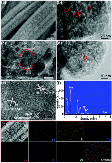
To understand the structural evolution of 4Co-SnS2/CC, the cycled batteries in the charge state after 100 cycles were disassembled in a glovebox and washed with dimethyl carbonate and absolute ethanol several times for SEM and TEM observation. Fig. 7a displays that the 4Co-SnS2/CC sample still maintains the 3D integrative skeleton and the nanosheets of Co-SnS2 without the CC substrate have been destroyed as shown in Fig. S8.† The nanosheets were divorced from the CC substrate and retain their original shape after cycling as observed in the TEM image in Fig. 7b, illuminating that the structure is robust enough to accommodate the volume change. Moreover, the nanosheets present many nanocrystals as encircled in red circles. For cycled SnS2/CC, the SEI film (like in the red circle) on the SnS2 surface is fairly thick and uneven (Fig. 7c), but it becomes thinner and more even after metal Co doping (Fig. 7d). The HRTEM image (Fig. 7e) presents some lattice fringes with the planes of (101), (101) and (220), which correspond to the lattice spacings of 2.74 (SnS2), 2.48 (Sn) and 2.35 Å (Na2S), respectively. The simultaneously existing Sn, Na2S and SnS2 can be attributed to the reversibility feature of reaction Sn + Na2S ↔ SnS2 with a CE of 97.9%, but it does not mean that the reversibility is poor, which is according to XRD patterns in Fig. 5a. The energy spectrum and marked SEM image of 4Co-SnS2/CC are shown in Fig. 7f and g. The Sn, S, Co, Na, O and Cl elements are still uniformly dispersed on the nanosheet surface shown by EDS exploration analysis.
Therefore, the excellent electrochemical performances of the 4Co-SnS2/CC anode can be ascribed to the following features. First, Co-doping can increase the interlayer spacing and generate lattice defects for the layered SnS2 crystal. The enlarged interlayer spacing could provide greater spacing for sodium ion intercalation and de-intercalation, improving the diffusion efficiency of Na-ions. Besides, it can suppress the destruction of the SnS2 structure during the cycling process. Therefore, Co-doping can boost the dynamic properties of sodium ions, modify the interaction force from the volume change, maintain the integrality of the crystal structure and offer plentiful electrochemical active sites for sodium storage, leading to high specific capacity and outstanding rate capability and cycling stability. Second, the rich defects can serve as additional active sites for sodium ion insertion. Third, Co-doping has possibility to regulate the electronic environment in the SnS2 crystal structure due to the different electronic states of Co2+/Co3+ with Sn4+,30 further enhancing the electron/Na-ion transfer efficiency and electrical conductivity. Finally, carbon cloth as a kind of current collector with good conductivity can provide strong mechanical toughness to significantly buffer the volume variation of SnS2 nanosheets and augment the sufficient contact area between the electrolyte and the active material to a great degree. Thus, the combination with the above advantages ultimately brings about superior cycling performance and rate capability of the interconnected Co-SnS2/CC nanosheet electrode.
3. Conclusions
In summary, we have employed a simple hydrothermal method to synthesize Co-doping SnS2/CC nanosheets. The 3D integrated skeleton of Co-SnS2 nanosheet arrays is homogeneously and vertically anchored on the CC substrate surface and directly used as an anode for SIBs without any binder or conductive agent. Remarkably, 4Co-SnS2/CC exhibits enhanced sodium storage properties with the discharge specific capacity as high as 1288 mA h g−1 at 0.2 A g−1 after 100 cycles with high initial coulomb efficiency and long-term cycling performance with a reversible capacity of 800.4 mA h g−1 at 2 A g−1 after 200 cycles, as well as outstanding rate capability. These excellent results can be attributed to the fact that Co-doping can enlarge interplanar spacing and lattice defects to increase active sites and enhance Na-ion insertion. Moreover, the CC substrate with robust mechanical toughness can effectively buffer the volume variation and maintain the integrality of Co-SnS2 nanosheets during the charge/discharge process. Thus, it is of great significance to exploit novel tactics to design and fabricate outstanding electrode materials for sodium storage and conversion devices.Conflicts of interest
There are no conflicts to declare.Acknowledgements
This work was financially supported by the National Natural Science Foundation of China (No. 21371023), the National Key Basic Research Program of China (2015CB251100), and the Beijing Institute of Technology Research Fund Program for Young Scholars (3090012221914).References
- S. Wenping, R. Xianhong, Y. Dan, S. Ziqi, L. Bing, Z. Wenyu, Z. Yun, M. Srinivasan, D. Shixue and Y. Qingyu, ACS Nano, 2015, 9, 11371–11381 CrossRef PubMed.
- Z. Wei, L. Wang, M. Zhuo, W. Ni, H. Wang and J. Ma, J. Mater. Chem. A, 2018, 6, 12185–12214 RSC.
- J. Mao, T. Zhou, Z. Yang, G. Hong and Z. Guo, J. Mater. Chem. A, 2018, 6, 3284–3303 RSC.
- L. Li, Z. Yang, S. Zhang, J. Yang and Z. Guo, Energy Environ. Sci., 2018, 11, 2310–2340 RSC.
- P. Zheng, Z. Dai, Y. Zhang, K. N. Dinh, Y. Zheng, H. Fan, J. Yang, R. Dangol, B. Li, Y. Zong, Q. Yan and X. Liu, Nanoscale, 2017, 9, 14820–14825 RSC.
- B. Qu, C. Ma, G. Ji, C. Xu, J. Xu, Y. S. Meng, T. Wang and J. Y. Lee, Adv. Mater., 2014, 26, 3854–3859 CrossRef CAS.
- A. Samad, M. Noor-A-Alam and Y. H. Shin, J. Mater. Chem. A, 2016, 4, 14316–14323 RSC.
- L. Fan, X. Li, X. Song, N. Hu, D. Xiong, A. Koo and X. Sun, ACS Appl. Mater. Interfaces, 2018, 10, 2637–2648 CrossRef CAS PubMed.
- Y. Pan, X. Cheng, L. Gong, L. Shi and H. Zhang, Nanoscale, 2018, 10, 20813–20820 RSC.
- B. Luo, Y. Hu, X. Zhu, T. Qiu, L. Zhi, M. Xiao, H. Zhang, M. Zou, A. Cao and L. Wang, J. Mater. Chem. A, 2018, 6, 1462–1472 RSC.
- W. Li, L. Zeng, Z. Yang, L. Gu, J. Wang, X. Liu, J. Cheng and Y. Yu, Nanoscale, 2014, 6, 693–698 RSC.
- Y. Liu, Y. Yang, X. Wang, Y. Dong, Y. Tang, Z. Yu, Z. Zhao and J. Qiu, ACS Appl. Mater. Interfaces, 2017, 9, 15484–15491 CrossRef CAS PubMed.
- Y. L. Bai, R. Xarapatgvl, X. Y. Wu, X. Liu, Y. S. Liu, K. X. Wang and J. S. Chen, Nanoscale, 2019, 11, 17860–17868 RSC.
- S. Tao, D. Wu, S. Chen, B. Qian, W. Chu and L. Song, Chem. Commun., 2018, 54, 8379–8382 RSC.
- Y. Liu, H. Kang, L. Jiao, C. Chen, K. Cao, Y. Wang and H. Yuan, Nanoscale, 2015, 7, 1325–1332 RSC.
- J. G. Wang, H. Sun, H. Liu, D. Jin, R. Zhou and B. Wei, J. Mater. Chem. A, 2017, 5, 23115–23122 RSC.
- Y. Fang, B. Y. Guan, D. Luan and X. W. D. Lou, Angew. Chem., Int. Ed., 2019, 58, 7739–7743 CrossRef CAS PubMed.
- C. Dong, L. Guo, Y. He, L. Shang, Y. Qian and L. Xu, Nanoscale, 2018, 10, 2804–2811 RSC.
- Q. Wang, W. Zhang, C. Guo, Y. Liu and Z. Guo, Adv. Funct. Mater., 2017, 27, 1–10 Search PubMed.
- S. Qi, D. Wu, Y. Dong, J. Liao, C. W. Foster, C. O'Dwyer, Y. Feng, C. Liu and J. Ma, Chem. Eng. J., 2019, 370, 185–207 CrossRef CAS.
- Y. Wang, F. Zhang, Y. Yu, Y. Yang, P. Mao, W. Guo, S. Rao, D. Wang and Q. Li, Electrochim. Acta, 2018, 282, 799–806 CrossRef CAS.
- K. Zhang, M. Park, L. Zhou, G. H. Lee, J. Shin, Z. Hu, S. L. Chou, J. Chen and Y. M. Kang, Angew. Chem., Int. Ed., 2016, 55, 12822–12826 CrossRef CAS PubMed.
- L. Wang, J. Yuan, Q. Zhao, Z. Wang, Y. Zhu, X. Ma and C. Cao, Electrochim. Acta, 2019, 308, 174–184 CrossRef CAS.
- X. Cui, W. Xu, Z. Xie and Y. Wang, J. Mater. Chem. A, 2016, 4, 1908–1914 RSC.
- L. Sun, W. Zhou, Y. Liu, D. Yu, Y. Liang and P. Wu, Appl. Surf. Sci., 2016, 389, 484–490 CrossRef CAS.
- N. Wang, P. Wu, L. Sun and W. Zhou, J. Phys. Chem. Solids, 2016, 92, 1–6 CrossRef CAS.
- G. Liu, Y. Qiu, Z. Wang, J. Zhang, X. Chen, M. Dai, D. Jia, Y. Zhou, Z. Li and P. Hu, ACS Appl. Mater. Interfaces, 2017, 9, 37750–37759 CrossRef CAS PubMed.
- Q. Chen, F. Lu, Y. Xia, H. Wang and X. Kuang, J. Mater. Chem. A, 2017, 5, 4075–4083 RSC.
- X. Gao, X. Yang, M. Li, Q. Sun, J. Liang, J. Luo, J. Wang, W. Li, J. Liang, Y. Liu, S. Wang, Y. Hu, Q. Xiao, R. Li, T.-K. Sham and X. Sun, Adv. Funct. Mater., 2019, 1806724, 1–8 Search PubMed.
- M. Herrera, D. Maestre, A. Cremades and J. Piqueras, J. Phys. Chem. C, 2013, 117, 8997–9003 CrossRef CAS.
- G. Wang, J. Peng, L. Zhang, J. Zhang, B. Dai, M. Zhu, L. Xia and F. Yu, J. Mater. Chem. A, 2015, 3, 3659–3666 RSC.
- Z. Yang, P. Zhang, J. Wang, Y. Yan, Y. Yu, Q. Wang and M. Liu, ACS Appl. Mater. Interfaces, 2018, 10, 37434–37444 CrossRef CAS PubMed.
- J. G. Wang, H. Sun, H. Liu, D. Jin, X. Liu, X. Li and F. Kang, ACS Appl. Mater. Interfaces, 2018, 10, 13581–13587 CrossRef CAS PubMed.
- Y. Zhang, N. Wang, P. Xue, Y. Liu, B. Tang, Z. Bai and S. Dou, Chem. Eng. J., 2018, 343, 512–519 CrossRef CAS.
- W. Ren, L. Xu, L. Zhu, X. Wang, X. Ma and D. Wang, ACS Appl. Mater. Interfaces, 2018, 10, 11642–11651 CrossRef CAS.
- Y. Xue, Q. Zhang, W. Wang, H. Cao, Q. Yang and L. Fu, Adv. Energy Mater., 2017, 7, 1–23 Search PubMed.
- Y. Liang, H. D. Yoo, Y. Li, J. Shuai, H. A. Calderon, F. C. R. Hernandez, L. C. Grabow and Y. Yao, Nano Lett., 2015, 15, 2194–2202 CrossRef CAS PubMed.
- Z. Zhang, H. Zhao, Z. Du, X. Chang, L. Zhao, X. Du, Z. Li, Y. Teng, J. Fang and K. Swierczek, ACS Appl. Mater. Interfaces, 2017, 9, 35880–35887 CrossRef CAS PubMed.
- P. Zhang, F. Qin, L. Zou, M. Wang, K. Zhang, Y. Lai and J. Li, Nanoscale, 2017, 12189–12195 RSC.
- Y. Zhang, P. Zhu, L. Huang, J. Xie, S. Zhang, G. Cao and X. Zhao, Adv. Funct. Mater., 2015, 25, 481–489 CrossRef CAS.
- H. Lu, R. Chen, Y. Hu, X. Wang, Y. Wang, L. Ma, G. Zhu, T. Chen, Z. Tie, Z. Jin and J. Liu, Nanoscale, 2017, 9, 1972–1977 RSC.
- M. Haruta, R. Hioki, T. Moriyasu, A. Tomita, T. Takenaka, T. Doi and M. Inaba, Electrochim. Acta, 2018, 267, 94–101 CrossRef CAS.
- J. Wang, C. Luo, J. Mao, Y. Zhu, X. Fan, T. Gao, A. C. Mignerey and C. Wang, ACS Appl. Mater. Interfaces, 2015, 7, 11476–11481 CrossRef CAS PubMed.
- M. G. Park, D. H. Lee, H. Jung, J. H. Choi and C. M. Park, ACS Nano, 2018, 12, 2955–2967 CrossRef CAS PubMed.
- Y. Zhao, B. Guo, Q. Yao, J. Li, J. Zhang, K. Hou and L. Guan, Nanoscale, 2018, 10, 7999–8008 RSC.
- Z. Zhu, A. Kushima, Z. Yin, L. Qi, K. Amine, J. Lu and J. Li, Nat. Energy, 2016, 1, 1–7 Search PubMed.
- X. Fan, E. Hu, X. Ji, Y. Zhu, F. Han, S. Hwang, J. Liu, S. Bak, Z. Ma, T. Gao, S. C. Liou, J. Bai, X. Q. Yang, Y. Mo, K. Xu, D. Su and C. Wang, Nat. Commun., 2018, 9, 1–12 CrossRef PubMed.
- L. Wu, X. Hu, J. Qian, F. Pei, F. Wu, R. Mao, X. Ai, H. Yang and Y. Cao, J. Mater. Chem. A, 2013, 1, 7181–7184 RSC.
- C. Ma, J. Xu, J. Alvarado, B. Qu, J. Somerville, J. Y. Lee and Y. S. Meng, Chem. Mater., 2015, 27, 5633–5640 CrossRef CAS.
- D. Chao, C. Zhu, P. Yang, X. Xia, J. Liu, J. Wang, X. Fan, S. V. Savilov, J. Lin, H. J. Fan and Z. X. Shen, Nat. Commun., 2016, 7, 12122 CrossRef CAS PubMed.
- H. Zhu, F. Zhang, J. Li and Y. Tang, Small, 2018, 14, 1–7 Search PubMed.
- Z. Wang, S. Rafai, C. Qiao, J. Jia, Y. Zhu, X. Ma and C. Cao, ACS Appl. Mater. Interfaces, 2019, 11, 7046–7054 CrossRef CAS PubMed.
Footnote |
| † Electronic supplementary information (ESI) available. See DOI: 10.1039/c9nr07849e |
| This journal is © The Royal Society of Chemistry 2020 |

