
Ultrathin layer solid transformation-enabled-surface enhanced Raman spectroscopy for trace harmful small gaseous molecule detection†
Haoming
Bao
 a,
Hongwen
Zhang
*a,
Hao
Fu
ab,
Le
Zhou
ab,
Peng
Zhang
ab,
Yue
Li
ab and
Weiping
Cai
*ab
a,
Hongwen
Zhang
*a,
Hao
Fu
ab,
Le
Zhou
ab,
Peng
Zhang
ab,
Yue
Li
ab and
Weiping
Cai
*ab
aKey Laboratory of Materials Physics, Anhui Key Laboratory of Nanomaterials and Nanotechnology, Institute of Solid State Physics, Chinese Academy of Sciences, Hefei 230031, P. R. China. E-mail: hwzhang@issp.ac.cn; wpcai@issp.ac.cn
bUniversity of Science and Technology of China, Hefei 230026, P. R. China
First published on 5th February 2020
Abstract
Detection of trace harmful small gaseous molecules (h-SGMs), based on surface enhanced Raman spectroscopy (SERS), has been expected to be a useful strategy but is challenging due to the extremely small Raman cross section (RCS) and weak metal affinity of the h-SGMs. Here, a new strategy, ultrathin layer solid transformation-enabled (ULSTE)-SERS, is proposed. It uses the chemical reaction between the target h-SGM and an ultrathin layer of solid sensing matter coated on a plasmonic metal SERS substrate. This reaction in situ produces a new solid matter with large RCS, which ensures the detection of trace h-SGMs via SERS. The validity of this strategy has been demonstrated by detecting trace H2S gas with an ultrathin CuO layer wrapped around Au nanoparticles. Furthermore, this strategy allows fast and ultrasensitive detection. The detection limit can be down to ppb (even ppt) levels with 10 min preprocessing. Importantly, this strategy has good universality for various other h-SGMs, such as SO2, CS2, CH3SH, and HCl, etc., using appropriate sensing matter. Additionally, the ULSTE-SERS is also suitable for unstable molecules and fast portable detection due to the stable solid layer. This work provides highly efficient SERS-based detection of trace h-SGMs, which is easily applied in practical situations.
New conceptsUltrasensitive detection of harmful small gaseous molecules (h-SGMs) has always been a bottleneck for surface enhanced Raman spectroscopy (SERS) technique due to the extremely small Raman cross sections (RCSs) of the h-SGMs. We report a new strategy, the ultrathin layer solid transformation-enabled (ULSTE)-SERS. In the strategy, the metal SERS substrate is coated with an ultrathin inorganic layer that can interact with the target h-SGM to in situ form a new solid matter with a large RCS, enabling the SERS detection of the h-SGM. The ULSTE-SERS is fast and ultrasensitive (ppt level h-SGMs can be detected within 10 min), because it simultaneously solves two key issues for efficient SERS detection: enhancing the metal-molecule affinity and enlarging the RCSs of the analyte directly. Such high efficiency is very rare in the literature. The ULSTE-SERS also has good universality, and is suitable for portable field detection and structurally diverse substrates. This work presents highly efficient SERS-based detection of trace h-SGMs, which is easily applied in practical situations. Additionally, it also provides a nimble approach to study the dynamic process of interfacial interactions between inorganic substances and gaseous molecules. This is important to deepen the understanding of small molecule catalysis and sensing. |
1 Introduction
Harmful small gaseous molecules (h-SGMs), such as H2S, H2, CH4, CO and Cl2, etc., are a serious threat to human health and property security due to their toxicity, combustibility and explosibility.1–3 Some of these can directly result in rapid dysfunction and acute poisoning, even at very low concentrations. In addition, although h-SGM concentrations may initially be low, it may provide a strong signal of imminent concentration increase because of the gradient of diffusion or continued leakage. Eventually, poisoning or explosion may result. Therefore, there are huge demands for fast and ultrasensitive detection of these molecules.Conventional detection of h-SGMs uses chromatography,4,5 and mass spectrometry;5 these are usually ultrasensitive. However, most of these are labor-intensive, time consuming and require sophisticated equipment, and thus make it difficult to realize both fast and facile detection. Novel techniques such as surface plasmon resonance based sensing,6,7 semiconductor oxide-based gas sensing,1,8 and fluorescent sensing2,9 have been developed for the fast and facile detection of h-SGMs but lack specificity.
Surface enhanced Raman spectroscopy (SERS) offers fast and ultrasensitive detection of analytes. It has ultrahigh sensitivities, molecular fingerprint identifications, and can use portable instrumentation, thus it has been extensively studied in the past few decades.10–16 However, SERS detection has been mainly focused on relatively large organic molecules with limited reports on h-SGMs. This is attributed to the extremely small Raman cross sections (RCSs) of the h-SGMs, which are usually less than 10−28 cm2 molecule−1 sr−1. In contrast, the Rhodamine 6G molecule, a widely used ideal SERS probe, has an RCS value of up to 10−23 cm2 molecule−1 sr−1.17 RCS is hugely dependent on the molecule size, and it reflects the probability of production of Raman photons and directly determines the Raman (or SERS) intensity of a Raman scatter.18 In addition, most h-SGMs interact very weakly with SERS substrates which are constructed with micro/nanostructured plasmonic metals (Au, and Ag, etc.). This further invalidates SERS detection for h-SGMs.18
To realize SERS-based detection of h-SGMs, some researchers have used SERS substrates coated with metal organic frameworks (MOFs),19–22 or modified with organic molecules,3,23 which can enrich the target molecules via physical trapping or adsorption. For instance, He et al. reported that MOF [Zn4O(BDC)3 (BDC = 1,4-benzenedicarboxylate)]-coated Au nanoparticles (NPs) can realize the enrichment and SERS-based detection of greenhouse gas CO2.19 Lafuente et al. used a citrate layer-modified SERS substrate to adsorb or capture the nerve agent simulant dimethyl methylphosphonate (DMMP) molecules and realized their SERS detection.23 For the MOF modifiers, the detection is often carried out only at high concentrations (or nearly pure gas phase). For the h-SGMs with much smaller RCSs (such as H2S: 10−36 to 10−34 cm2 molecule−1 sr−1![[thin space (1/6-em)]](https://www.rsc.org/images/entities/char_2009.gif) 24 and C2H2: about 10−36 cm2 molecule−1 sr−125) at a very low concentration (ppm or even ppb level), such detection would be inefficient. For organic modifiers, they could easily disturb the detection environment due to their weak photothermal stability, and increase the complexity of the spectral pattern, even sheltering the signal of the target molecules. In general, facile and efficient SERS-based detection of trace h-SGMs has not yet been demonstrated.
24 and C2H2: about 10−36 cm2 molecule−1 sr−125) at a very low concentration (ppm or even ppb level), such detection would be inefficient. For organic modifiers, they could easily disturb the detection environment due to their weak photothermal stability, and increase the complexity of the spectral pattern, even sheltering the signal of the target molecules. In general, facile and efficient SERS-based detection of trace h-SGMs has not yet been demonstrated.
Here we conceive a new strategy – the ultrathin layer solid transformation-enabled (ULSTE)-SERS – for the highly efficient detection of trace h-SGMs. In this strategy, the plasmonic metal SERS substrate is coated with an ultrathin layer of solid sensing matter that can strongly interact and react with a target h-SGM to in situ form a new solid phase (matter) with a large RCS. This facilitates efficient SERS-based detection of the target h-SGM. The validity of this ULSTE-SERS strategy has been confirmed by taking gaseous H2S as the target molecule, and using an ultrathin CuO layer which was wrapped around Au NPs, as the solid sensing matter. It has been demonstrated that this strategy achieves fast and ultrasensitive detection. In our experiment, the limit of detection (LoD) can be down to ppt levels with preprocessing of 10 min. Moreover, this strategy is of universality and can be used to detect some other trace h-SGMs using appropriate solid sensing matter comprised of layer-coated SERS substrates. Finally, the ULSTE-SERS well-supports portable detection requiring high-power excitation due to the stable new solid layer.
2 ULSTE-SERS strategy
The RCS reflects the probability that Raman photons are produced. It is determined by the structural geometry, polarization, and electron density of the target molecules as well as the incident laser wavelength.18 The h-SGMs have very small RCSs (less than 10−28 cm2 molecule−1 sr−1) because they have few electron-rich atoms;18 thus they show extremely weak SERS signals. In contrast, solid and crystalline substances have much larger RCSs,18,26 and thus are good Raman scatters. If a SERS-active substrate is covered with an ultrathin layer of solid sensing matter that can strongly interact and react with a target h-SGM to in situ transform into a new solid matter, what we call “ultrathin layer solid transformation (ULST)”, it is expected that the h-SGM could be effectively detected due to the SERS-active substrate and the solid phase with a large RCS.Fig. 1 schematically shows the strategy of ULSTE-SERS. Firstly, an ultrathin layer of sensing matter (such as oxide, sulfide or some other compounds), which can strongly interact and react with a target h-SGM, is designed and wrapped around the surface of a nanostructured plasmonic metal (gold and silver, etc.) which has strong SERS activity (Fig. 1a). When these coated metals are exposed to the detecting environment, the wrapping layer will capture and chemically react with the target h-SGM to in situ form new solid matter with a large RCS (Fig. 1a and b). Thus, we can finally easily acquire the Raman spectrum of this new solid matter, which reflects and directly corresponds to the target h-SGM, due to the strong SERS activity of the plasmonic metals and the large RCS of the new solid layer (Fig. 1c).
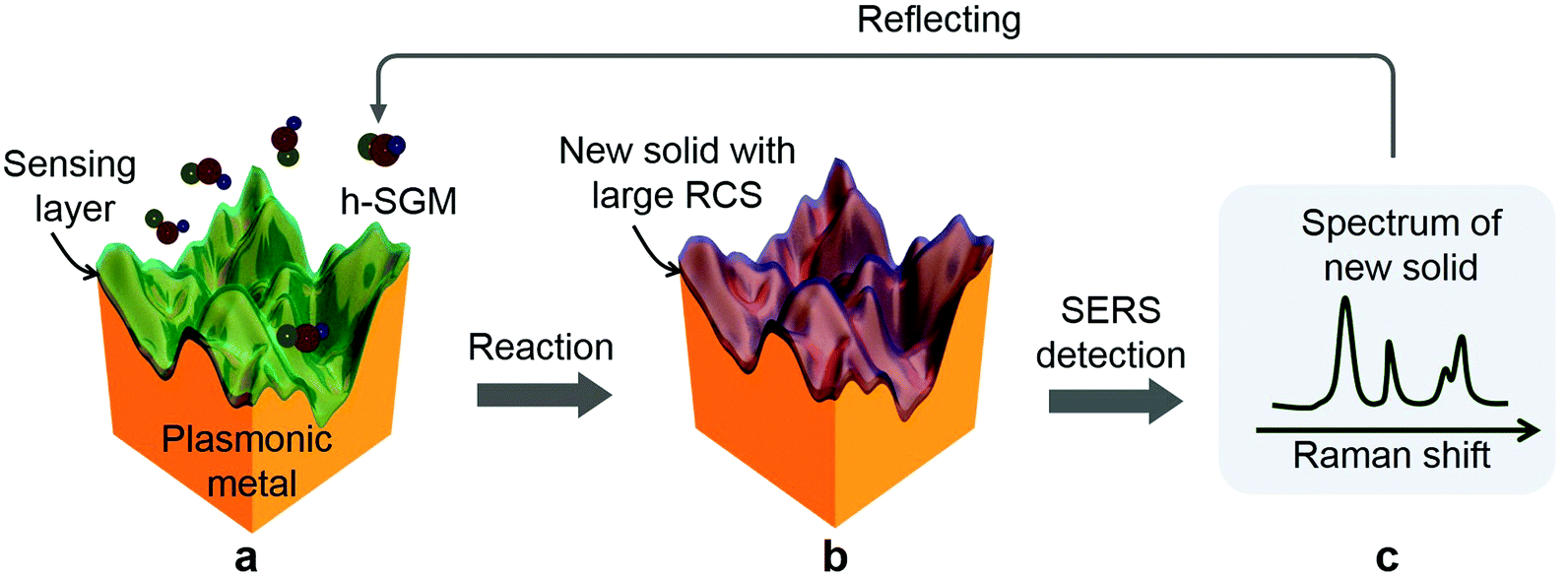 | ||
| Fig. 1 A schematic illustration of the ULSTE-SERS strategy. (a) A sensing matter-wrapped plasmonic metal exposed to the detection environment with target h-SGM. (b) Reaction-induced new solid matter-wrapped plasmonic metal. (c) A SERS spectrum of the new solid layer, which reflects and directly corresponds to the target h-SGM. | ||
Here, the sensing matter is crucial and should strongly and specifically react with the target molecules to in situ form a new solid phase. The sensing matter layer should be uniform and have an appropriate thickness such that the chemical reaction in the layer is quickly finished with a sufficient amount of the new solid matter formed for fast and sensitive detection. An excessively thin layer cannot capture sufficient target substance, while an overly thick layer will mask the plasmonic metal core's strong electromagnetic field (generally restricted to the first 10 nm).13 Furthermore, a solid sensing matter layer-coated SERS substrate, or the composite of the SERS-active substrate and the solid sensing matter, should be able to be varied in structure. Finally, this strategy should be universal. Here, we firstly use a CuO layer to wrap a Au NP film as the substrate, and gaseous H2S as the target h-SGM, to demonstrate the validity of this ULSTE-SERS strategy on the basis of gas-solid reaction between the H2S gas and the CuO layer (Fig. 2a).27
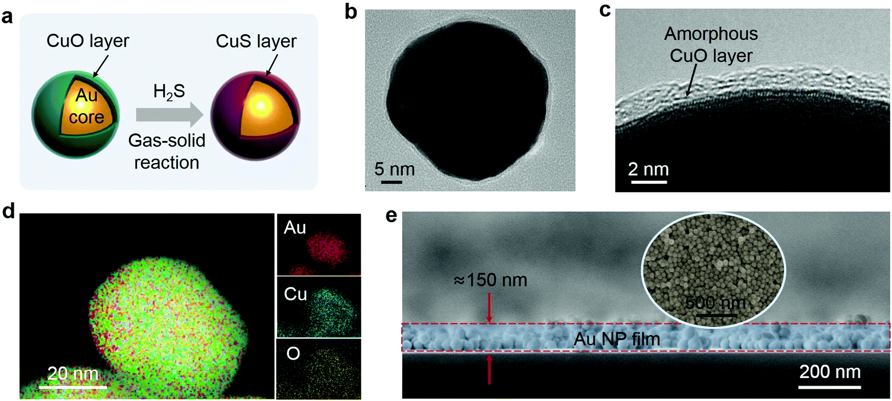 | ||
| Fig. 2 (a) A schematic illustration of the interaction between the Au@CuO NP and the H2S gas. (b) A TEM image of an isolated NP. (c) A HRTEM image of a NP. (d) An EDS elemental map of Au, Cu and O. (e) An FESEM image of the cross section of the substrate. The inset is a top-view image. | ||
3 Results and discussion
3.1 Structure and morphology of the Au@CuO substrate
The thin CuO layer-wrapped Au NPs (or Au@CuO NPs) were fabricated based on colloidal electrostatic self-assembly28 (see the ESI† for details). The composite Au@CuO SERS substrates were prepared by electrophoretic deposition of the Au@CuO NPs onto a piece of silicon wafer, and cutting the silicon wafer into a size of 1 mm × 1 mm.Transmission electron microscopy (TEM) examination reveals that the Au NPs are nearly spherical in shape with a size of about 50 nm (Fig. S1a, ESI†). They are homogeneously wrapped by a thin layer of amorphous CuO about 2 nm in thickness, as typically shown in Fig. 2b and c. The energy dispersion spectrum (EDS) (Fig. S1b, ESI†) and corresponding elemental mappings (Fig. 2d) of the Au@CuO NPs show the presence of the elements Au, Cu, and O in the NPs. The FESEM image (Fig. 2e) shows that the Au@CuO NP film is dense and about 150 nm thick. The Raman spectrum of the film shows the well-defined vibrational bands at 295, 340 and 615 cm−1, which match well with the Raman pattern of CuO29 (this will be covered later).
3.2 ULSTE-SERS detection of the H2S gas
Raman spectral measurements were conducted for this composite SERS substrate, as shown in Fig. 3a (curve I). The data shows that the spectrum of the substrate shows the typical pattern of CuO.29 After exposure to the H2S gas (100 ppb for 10 min), these bands vanish, and new bands appear at 270, 470 and 925 cm−1. The new bands agree with the Raman vibrations of CuS crystal,30,32 as illustrated by curve II in Fig. 3a. In contrast, pure Au NPs or pure CuO NPs have no responses to the H2S gas in their Raman spectral measurements (curves III and IV in Fig. 3a). Obviously, the successful acquisition of the Raman signals from the exposed wrapped NPs should be attributed to the co-contribution of the large RCS of the CuS shells and the Au NPs strong SERS effect. | ||
| Fig. 3 (a) Raman spectra of the Au@CuO NPs before (I) and after (II) exposure to H2S gas (100 ppb, 500 mL) for 10 min, and those corresponding to the Au NPs (III) and CuO NPs (IV) substrates (with the same molar number to that of the Au@CuO NP substrate) after exposure. (b) A SERS map. (c) Distribution of SERS intensity of points in the mapping area (corresponding to b). (d) An EDS spectrum of the H2S-exposed NPs, and the elemental mapping (the inset) of Au, Cu and S. (e) EDS mapping of the H2S-exposed NPs. (f) An HRTEM image of a H2S-exposed NP. | ||
Further studies show that such a substrate can realize signal-stable detection. We randomly selected 10 positions on the substrate for testing, and the data shows that the substrate is very uniform in the signal intensity, the relative standard deviation (RSD) is about 8.8%, as shown in Fig. S2 (ESI†). Further, the SERS intensity mapping (referring to the characteristic vibration of CuS at 470 cm−1) in a randomly chosen 80 μm × 80 μm area shows homogeneously distributed signal intensity, as shown in Fig. 3b. Quantitatively, the statistical intensities of these detected points in the mapping area has a RSD of 9.6% (Fig. 3c), suggesting the high uniformity of the substrate. This matches well with the results of tests performed with randomly selected 10 positions.
EDS analyses show that these H2S gas-exposed NPs contain S and Cu in addition to Au (Fig. 3d). The TEM examination shows that the H2S-exposed NPs retain their core–shell structure (Fig. S1c, ESI†), but the wrapping layer is a crystalline CuS shell (Fig. 3e). These confirm that the amorphous CuO layer is transformed to a crystalline CuS layer after interaction with H2S gas according to the reduced Gibbs free energy, as typically shown in Fig. 3f or described by eqn (1):27
| CuO(s) + H2S(g) → CuS(s) + H2O(g), ΔG = −161 kJ mol−1 | (1) |
The process of gas-solid reaction involves the migration and rearrangement of atoms. From the point of view of thermodynamics, the free energy of the crystal is lower than that of the amorphous form.31 Therefore, during the formation of the CuS layer, it tends to nucleate and grow ordered crystalline CuS via such atomic migration and rearrangement.
The CuS shell has shown strong Raman signals due to its much higher RCS than the gaseous H2S molecules and the gold core's strong SERS effect. Here the Raman signals from CuS shell reflect or correspond to the gaseous H2S molecules. Thus, we can detect the trace H2S molecules via the ULSTE-SERS strategy.
3.3 Fast detection and high sensitivity
Preprocessing time and LoD are two important parameters for detection. Here we evaluate them separately. For the preprocessing time, we in situ monitored the Raman spectra evolution with self-made equipment (Fig. S3, ESI†) with H2S gas injection. It is found that the NPs can respond to the H2S (100 ppb) within 5 s, showing very fast detection. In addition, as the exposure time increases, the intensity of the CuS peak gradually increases. After 25 s, the detected Raman intensity reaches a saturation value, as shown in Fig. 4a and b.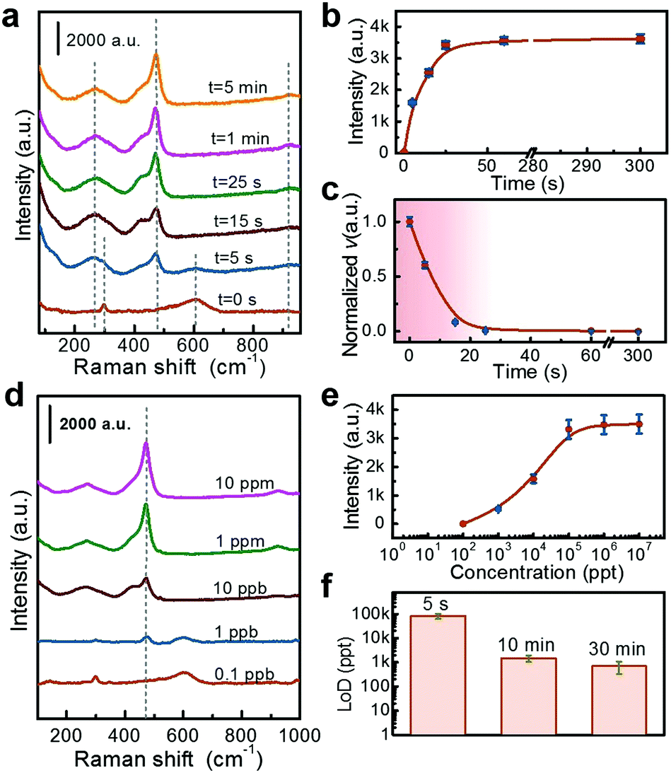 | ||
| Fig. 4 (a) Raman spectral evolution after H2S gas (100 ppb, 100 mL) injection. (b) The plot of spectral intensity (referring to the peak at 470 cm−1) versus the preprocessing time corresponding to (a). (c) The plot of normalized reaction velocity (v) versus the time corresponding to (b). (d) Raman spectra achieved at different H2S concentrations (the volume of the test environment is 500 mL, and the exposure time is 10 min). (e) The plot of Raman intensity versus the H2S concentration. (f) LoDs achieved with different preprocessing time. | ||
If the intensity of the Raman signal is considered to be proportional to the amount of the detection substance, the first-order differential of peak intensity (I) versus time (t) reflects the velocity of reaction (v), or as described by eqn (2):
| v ∝ ΔI/Δt | (2) |
According to eqn (2) and the data in Fig. 4a, the velocity of the reaction decreases gradually, as shown in Fig. 4c. Such a fast to slow process is consistent with the kinetics of typical gas-solid reactions.33
The LoD was measured by exposing the Au@CuO substrate to H2S gas at different concentrations for 10 min. It is found that the CuS peak at 470 cm−1 gradually shrinks with the decrease of concentration, and the LoD is about 0.1 ppb (Fig. 4d). The dynamic range of this detection is 0.1 ppb to 1 ppm, and a saturated signal intensity is obtained at high concentrations (say at 100 ppb), as shown in Fig. 4e. The saturated signal intensity is due to the finite thickness of the induced CuS shell. The limited amount of CuO shell can only produce a CuS layer of constant thickness even with excess H2S gas. This is supported by the relative calculations (see the ESI† for details).
As the chemical reaction involved detection, the corresponding LoD should be closely dependent on the exposure time since reactions need a certain duration to finish. Fig. 4f shows the LoDs obtained under different exposure times. With the time extended from 5 s to 0.5 h, the LoD decreases gradually from 100 ppb to ppt levels.
3.4 Influence factors
Further experiments have demonstrated that the volume of the test environment, the thickness of the CuO wrapping layer and the thickness of the Au@CuO NP film have significant influences on detection properties.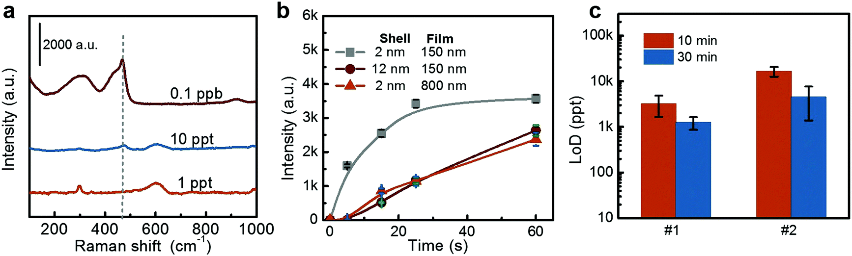 | ||
| Fig. 5 (a and b) Raman spectra achieved at different H2S concentrations (the polluted volume is enlarged to 20 L, and the exposure time is 10 min). (b) The Raman intensity evolution (referring to the peak at 470 cm−1) versus the exposure duration with different substrate parameters. The concentration of H2S gas is 100 ppb and the volume of the test environment is 500 mL. (c) LoDs achieved by the two substrates with different parameters after 10 min and 30 min. The #1 presents the 12 nm thick CuO wrapped Au NPs film with film thickness of 150 nm. The #2 presents the 2 nm thick CuO wrapped Au NPs film with film thickness of 800 nm. | ||
For the NPs with a CuO shell of 12 nm, the SERS activity is weak at the outer layer and strong at inner portions of the shell. When it reacts with H2S, the transformation of the inner CuO located in the strong SERS active region takes longer compared with that for the 2 nm thick CuO layer wrapped NPs. Similarly, the 800 nm thick film requires more time for gas to diffuse into it, resulting in a relatively slow response. A thicker wrapping layer and NP film both require more H2S molecules to convert the CuO into CuS. Therefore, under a fixed test environment, the required concentration of H2S is higher, and the corresponding LoDs are higher.
3.5 Good universality
Importantly, the good versatility of the ULSTE-SERS also was confirmed by later experiments. Using the Au@CuO substrate, distinguishable detection of other h-SGMs (such as SO2 and CS2) can also be realized, as shown in Fig. 6a. The peaks at 679, 638 and 502 cm−1 match with the sulfites, and the peaks at 270, 423, 468 and 502 cm−1 match with the amorphous CuS.34 The corresponding reactions are described by eqn (3)35 and eqn (4),36 respectively.| CuO(s) + SO2(g) → CuSO3(s) | (3) |
| 2CuO(s) + CS2(g) → 2CuS(s) + CO2(g) | (4) |
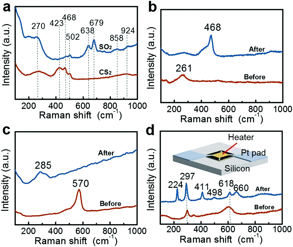 | ||
| Fig. 6 (a) Response of Au@CuO NPs to CS2 and SO2 gas. (b) Response of Au@Cu(OH)2 NPs to H2S gas. (c) Response of Au@ZnO NPs to HCl gas. (d) Raman spectra of the Au@CuO NPs-coated MEMS-heating chip before (I) and after (II) exposure to gaseous CH3SH molecules (1 ppm) for 10 min, with heating temperature of 250 °C. The inset is a schematic diagram of the MEMS-heating chip. | ||
In addition, Au@Cu(OH)2 and Au@ZnO NP films can be used as substrates for the detection of H2S and HCl molecules, respectively, as shown in Fig. 6b and c. These two kinds of NPs were also fabricated according to colloidal electrostatic self-assembly28 (their TEM spectra are presented in Fig. S5, and see the ESI† for relative fabrication details). In Fig. 6b, the peaks at 261 and 468 cm−1 match with Cu(OH)237 and CuS,30,32 respectively. In Fig. 6c, the peaks at 570 and 285 cm−1 match with ZnO38 and ZnCl2,39 respectively. The corresponding reactions are described in eqn (5)40 and eqn (6),41 respectively:
| Cu(OH)2(s) + H2S(g) → CuS(s) + 2H2O(g) | (5) |
| ZnO(s) + 2HCl(g) → ZnCl2(s) + H2O(g) | (6) |
More importantly, for many chemical reactions that occur at temperatures higher than room temperature, we can fabricate the composite SERS substrate on a micro-electro-mechanical system (MEMS)-based heating chip. The MEMS-heating chip has been described in our previous work.42 Briefly, the working area located in the central part of the chip is about 150 μm × 150 μm in size, and two Pt pads distributed at two opposite corners are the electrodes for electric heating (inset in Fig. 6d). The temperature was controlled via input-voltage. The Au@CuO NP film was coated onto the work area of the chip. After exposure to the gaseous CH3SH molecules (1 ppm) for 10 min at a chip temperature of 250 °C, a new pattern appeared as shown in curve II in Fig. 6d. The peak at 297 cm−1 is derived from CuO,29 the peak at 224 and 411 cm−1 belongs to Cu2O, the peak at 498 and 660 cm−1 is derived from CuSO3, and the peak at 618 cm−1 can be contributed to by CuO and CuSO3.43 Contrarily, if exposing to gaseous CH3SH without heating, only the Raman pattern of CuO can be observed (similar to curve I in Fig. 6d).
3.6 Structural diversity of substrates
Based on the strategy mentioned above, the composite SERS substrates can be constructed by combining the sensing matter with SERS-active materials, and thus the substrates should have diverse structures and components. Here, we present an alternative substrate: a thin CuO layer coated onto gold nanoshell films on a polystyrene sphere (PS) colloidal monolayer (or CuO/Au/PS) for H2S molecule detection.The CuO/Au/PS substrate was fabricated by sputtering deposition of Au and then Cu on the self-assembled PS colloidal monolayer on a Si wafer before surface oxidation treatment (see ESI† for the fabrication details). Fig. 7a and b show the corresponding results. The self-assembled PS colloidal monolayer was coated with Au/CuO hetero-double layer from the inside to the outside. The Au and CuO layers are about 50 nm and 5 nm thick, respectively. Further experiments show that such substrate also can be used for the detection of trace H2S gas. Before detection, this substrate has a Raman spectral pattern with three peaks at 295, 340 and 615 cm−1 (see Fig. S6, ESI†), which agrees with that of CuO.29 After exposure to H2S gas (10 ppb) for 10 min, we can obtain a Raman pattern of CuS, accompanied by complete disappearance of the peaks from CuO; both the CuO layer and the Au nanoshell on PS array with strong SERS activity are indispensable for such detection, as shown in Fig. S6 (ESI†). Further studies show such detected signal is stable, as shown by the SERS mapping (Fig. 7c) referring to the CuS peak at 470 cm−1. Quantitatively, the statistical intensities of the detected points in the mapping area have an RSD of 8.5% (Fig. 7d). The different combinations of both components induce structural diversity of the composite SERS substrates and different performances. The structural diversity means that the SERS activity of the substrate is highly tunable, and a substrate with higher SERS activity can achieve lower LoDs. Therefore, the ULSTE-SERS is expected to achieve more sensitive detection using higher SERS-active substrates coated in a sensing layer.
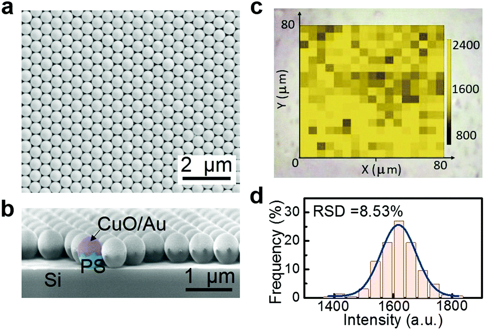 | ||
| Fig. 7 The top view (a), and the cross-sectional view (b), of the CuO/Au/PS substrate by SEM observation (coloring added for clarity). (c) SERS mapping of the CuO/Au/PS substrate after exposure to 100 ppb H2S for 10 min (referring to the CuS peak at 470 cm−1). (d) Frequency distribution of SERS intensity of points in the mapping area (corresponding to c). | ||
By controlling the deposition time and deposition rate, we have prepared CuO/Au/PS arrays with different thickness of CuO layer (2, 5, 10 and 15 nm). The testing results show that with the increase of the thickness of the shell, the response to H2S becomes sluggish and relatively insensitive (see the Fig. S7, ESI†). This highly agrees with the results from Fig. 5b.
In addition to the rapidity, ultrasensitivity, good universality and good substrate diversity, the ULSTE-SERS also has some other advantages. It is easy to realize highly selective detection using appropriate sensitive layers, which can selectively react with the targets. For example, the CuO layer coated Au NPs can realize such selective detection of sulfur-containing gas. After exposure to an interfering gas (such as H2O, HCl, CO, C6H6 and C2H6O) mixed with H2S gas, the Au@CuO NP substrate still accurately detects target H2S without any obvious interference, as shown in Fig. S8 (ESI†). Of course, such a substrate is responsive to other sulfur-containing gases (such as CS2, SO2, CH3SH), and these gas can be recognized through the different SERS patterns, as shown in Fig. 6a and d. Because of the large RCS, the solid can be easily detected. Thus, what affects the LoD should be the degree of solid transformation (or the reaction between the gas molecule and sensitive layer). This indicates that even if the substrate’s SERS activity is not particularly high, it can still achieve ultrasensitive detection (or low LoD), as long as the ultrathin layer transformation is carried out. The ULSTE-SERS strategy converts target h-SGMs (including small organic molecules) into inorganic layers with large RCSs. The inorganic layers are usually more stable than the organic molecules. Therefore, ULSTE-SERS allows high excitation power to obtain strong Raman signals compared with conventional SERS detection of organic molecules. In general, the ULSTE-SERS detection is very suitable for unstable molecules, substances with low RCSs, and portable Raman detection requiring high-power excitation (tens to hundreds of milliwatts)44 and will play a key role in the fast and on-site SERS detection.
4 Conclusions
In summary, we have presented and established a ULSTE-SERS strategy for trace and efficient detection of h-SGMs. The detection is performed through a chemical reaction between the target h-SGM and the ultrathin layer of solid sensing matter on a SERS-active substrate to in situ produce a new solid phase with large RCS, and subsequent SERS measurement of the new solid phase mirrors the target h-SGM. The principle and feasibility of this strategy are demonstrated by the detection of H2S gas with ultrathin CuO layer-wrapped Au NPs as an example. The detection is fast and ultrasensitive, and with a preprocessing time of 10 min, the LoD can be down to ppt levels in lab conditions, and it can be further lowered in the actual detection. The influence of the thicknesses of the CuO layer and Au@CuO NP film are also investigated: thick wrapping layers and NP films both cause slow responses and relatively high LoDs. Importantly, this strategy is of good universality for various h-SGMs (such as SO2, CS2, CH3SH and HCl, etc.) with using corresponding sensing matter. In addition to the sensing matter-wrapped plasmonic NPs, a thin layer of sensing matter coated onto gold nanoshell arrays also can be used as an efficient ULSTE-SERS substrate, showing the structural diversity of the substrate. Finally, compared with conventional SERS, the ULSTE-SERS is more suitable for substances with low RCSs, unstable molecules, and portable Raman detection requiring high-power excitation.The ULSTE-SERS established in this work has great practical value for highly efficient SERS-based detection. In addition, this strategy could also provide an efficient and nimble approach to study the dynamic process of the interfacial interaction between functional films and small molecules, even ions. This will be important to deepen the understanding of small molecule catalysis and sensing.
5 Experimental methods
The preparation of sensing matter [CuO, Cu(OH)2 and ZnO]-wrapped Au NPs and the CuO/Au/PS substrates are described in the ESI.†5.1 Characterizations
The morphological observations were conducted on a field emission scanning electron microscope (FEI Sirion 200) for the solid sensing matter-wrapped Au NPs and CuO/Au/PS substrate. The transmission electron microscopy (TEM) examination and composition analyses were carried out on a transmission electron microscope (FEI Tecnai G2 F20, USA) attached with an energy dispersion spectroscope (Oxford IE250X-Max50).5.2 Raman spectral measurements
The composite SERS substrates were first fabricated via respective electrophoretic deposition of the Au@sensing matter [CuO, Cu(OH)2, ZnO] NP on a silicon wafer and cutting the wafer into 1 mm × 1 mm size (see the ESI† for details). The CuO/Au/PS substrate was obtained by cutting the wafer with CuO/Au/PS film into pieces 1 mm × 1 mm in size. For the detection of gaseous molecules based on SERS, the corresponding composite SERS substrate was firstly placed in a chamber with a volume of 500 mL which was then closed. The target gas was then injected into the chamber via a syringe. After exposure to the target gas for a certain time, the substrate was taken out for Raman spectral measurement. The concentration of the target gas in the closed chamber was determined by the injection amount, its initial concentration and the chamber volume. The used H2S and SO2 gases were 1 ppm in initial concentration and mixed with argon before injection. CS2, HCl and CH3SH gases were achieved using their saturated vapors.The SERS measurements were performed on a Renishaw Invia confocal Raman spectrometer. The excitation wavelength was 633 nm with 1.7 mW μm−2 power, and the integral time was 5 s for spectral measurements and 1 s for the mapping measurements.
Conflicts of interest
There are no conflicts to declare.Acknowledgements
This work is financially supported by the National Key Research and Development Program of China (Grant No. 2017YFA0207101), National Natural Science Foundation of China (Grant No. 11974352, 51771182 and 51531006), and Chinese Postdoctoral Science Foundation (Grant No. 2019M662211).Notes and references
- Z. Xu, G. Duan, Y. Li, G. Liu, H. Zhang, Z. Dai and W. Cai, Chem. – Eur. J., 2014, 20, 6040–6046 CrossRef CAS PubMed.
- J. Yao, Y. Fu, W. Xu, T. Fan, Y. Gao, Q. He, D. Zhu, H. Cao and J. Cheng, Anal. Chem., 2016, 88, 2497–2501 CrossRef CAS PubMed.
- Q. Zhao, G. Liu, H. Zhang, F. Zhou, Y. Li and W. Cai, J. Hazard. Mater., 2016, 324, 194–202 CrossRef PubMed.
- J. E. Oberholtzer and L. B. Rogers, Anal. Chem., 1969, 41, 1234–1240 CrossRef CAS.
- R. Lopez, M. Aznar, J. Cacho and V. Ferreira, J. Chromatogr. A, 2002, 966, 167–177 CrossRef CAS PubMed.
- K. Nakamoto, R. Kurita and O. Niwa, Anal. Chem., 2012, 84, 3187–3191 CrossRef CAS PubMed.
- E. D. Gaspera, M. Guglielmi, S. Agnoli, G. Granozzi, M. L. Post, V. Bello, G. Mattei and A. Martucci, Chem. Mater., 2010, 22, 3407–3417 CrossRef.
- Z. R. Tian, J. A. Voigt, J. Liu, B. Mckenzie, M. J. Mcdermott, M. A. Rodriguez, H. Konishi and H. Xu, Nat. Mater., 2003, 2, 821–826 CrossRef CAS PubMed.
- J. Wu, W. Liu, J. Ge, H. Zhang and P. Wang, Chem. Soc. Rev., 2011, 40, 3483–3495 RSC.
- M. Fleischmann, P. J. Hendra and A. J. McQuillan, Chem. Phys. Lett., 1974, 26, 163–166 CrossRef CAS.
- M. Martin, Rev. Mod. Phys., 1985, 57, 783–826 CrossRef.
- S. Nie and S. R. Emory, Science, 1997, 275, 1102–1106 CrossRef CAS PubMed.
- J. Li, Y. Huang, Y. Ding, Z. Yang, S. Li, X. Zhou, F. Fan, W. Zhang, Z. Zhou and D. Wu, Nature, 2010, 464, 392–395 CrossRef CAS PubMed.
- R. Pilot, J. Raman Spectrosc., 2018, 49, 954–981 CrossRef CAS.
- S. Yang, X. Dai, B. M. Boschitsch and T. Wong, Proc. Natl. Acad. Sci. U. S. A., 2016, 113, 268–273 CrossRef CAS PubMed.
- X. Zhang, X. Zhang, C. Luo, Z. Liu, Y. Chen, S. Dong and X. Xiao, Small, 2019, 15, 1805516 CrossRef PubMed.
- S. Shim, C. M. Stuart and R. A. Mathies, ChemPhysChem, 2010, 9, 697–699 CrossRef PubMed.
- R. A. Alvarez-Puebla and L. M. Liz-Marzàn, Angew. Chem., Int. Ed., 2012, 51, 11214–11223 CrossRef CAS PubMed.
- L. He, Y. Liu, J. Liu, Y. Xiong, J. Zheng, Y. Liu and Z. Tang, Angew. Chem., Int. Ed., 2013, 52, 3741–3745 CrossRef CAS PubMed.
- Y. Liu and Z. Tang, Adv. Mater., 2013, 25, 5819–5825 CrossRef CAS PubMed.
- L. Kreno, N. G. Greeneltch, O. K. Farha, J. T. Hupp and R. P. Van Duyne, Analyst, 2014, 139, 4073–4080 RSC.
- C. Koh, H. Lee, X. Han, H. Sim and X. Ling, Chem. Commun., 2018, 54, 2546–2549 RSC.
- M. Lafuente, I. Pellejero, V. Sebastiàn, M. A. Urbiztondo, R. Mallada, M. P. Pina and J. Santamaría, Sens. Actuators, B, 2018, 267, 457–466 CrossRef CAS.
- J. M. Fernàndez-Sànchez and W. F. Murphy, J. Mol. Spectrosc., 1992, 156, 431–443 CrossRef.
- K. M. Gough and W. F. Murphy, J. Chem. Phys., 1986, 85, 4290–4296 CrossRef CAS.
- L. G. Cançado, A. Jorio and M. A. Pimenta, Phys. Rev. B: Condens. Matter Mater. Phys., 2007, 76, 3009–3014 CrossRef.
- A. Galtayries and J. P. Bonnelle, Surf. Interface Anal., 1995, 23, 171–179 CrossRef CAS.
- H. M. Bao, H. W. Zhang, L. Zhou, G. Q. Liu, Y. Li and W. P. Cai, Langmuir, 2017, 33, 12934–12942 CrossRef CAS PubMed.
- J. Xu, W. Ji, Z. X. Shen, S. H. Tang, X. R. Ye, D. Z. Jia and X. Q. Xin, J. Solid State Chem., 1999, 147, 516–519 CrossRef CAS.
- P. Kumar and R. Nagarajan, Inorg. Chem., 2011, 50, 9204–9206 CrossRef CAS PubMed.
- V. V. Brazhkin, J. Non-Cryst. Solids, 1990, 124, 34–40 CrossRef CAS.
- Y. Xie, G. Bertoni, A. Riedinger, A. Sathya, M. Prato, S. Marras, R. Tu, T. Pellegrino and L. Manna, Chem. Mater., 2015, 27, 7531–7537 CrossRef CAS PubMed.
- S. K. Bhatia and D. D. Perlmutter, AlChE J., 2010, 29, 79–86 CrossRef.
- J. R. Hall and R. A. Johnson, J. Raman Spectrosc., 1981, 11, 279 CrossRef CAS.
- C. S. Shin and H. Niiyama, J. Jpn. Pet. Inst., 1988, 31, 147–153 CrossRef.
- O. M. Saad, T. Kuzuya, S. Hirai and M. Ohta, Mater. Trans., 2010, 51, 2289–2293 CrossRef CAS.
- W. Wang, Y. Zhuang, Z. Wang, Y. Zhang, X. Zhong, N. An and G. Zhang, Mater. Lett., 2009, 63, 2432–2434 CrossRef CAS.
- X. Q. Wei, B. Y. Man, M. Liu, C. S. Xue, H. Z. Zhuang and C. Yang, Phys. B, 2007, 388, 145–152 CrossRef CAS.
- F. Aliotta, G. Maisano, P. Migliardo, C. Vasi, F. Wanderlingh, G. P. Smith and R. Triolo, J. Chem. Phys., 1981, 75, 613–618 CrossRef CAS.
- G. Hou, Z. Cheng, L. Kang, X. Xu, F. Zhang and H. Yang, CrystEngComm, 2015, 17, 5496–5501 RSC.
- M. S. Spencer, Top. Catal., 1999, 8, 259–266 CrossRef CAS.
- Z. Dai, L. Xu, G. Duan, T. Li, H. Zhang, Y. Li, Y. Wang and W. Cai, Sci. Rep., 2013, 3, 1669 CrossRef PubMed.
- M. Balkanski, M. A. Nusimovici and J. Reydellet, Solid State Commun., 1969, 7, 815–818 CrossRef CAS.
- D. S. Moore and R. J. Scharff, Anal. Bioanal. Chem., 2009, 393, 1571–1578 CrossRef CAS PubMed.
Footnote |
| † Electronic supplementary information (ESI) available. See DOI: 10.1039/c9nh00799g |
| This journal is © The Royal Society of Chemistry 2020 |