Nanoengineering to achieve high efficiency practical lithium–sulfur batteries
Eunho
Cha
a,
Mumukshu
Patel
a,
Sanket
Bhoyate
a,
Vish
Prasad
b and
Wonbong
Choi
 *ab
*ab
aDepartment of Materials Science and Engineering, University of North Texas, North Texas Discovery Park, 3940 North Elm St. Suite E-132, Denton, TX 76207, USA. E-mail: Wonbong.Choi@unt.edu
bDepartment of Mechanical and Energy Engineering, University of North Texas, North Texas Discovery Park, 3940 North Elm St. Suite F-101, Denton, TX 76207, USA
First published on 19th February 2020
Abstract
Rapidly increasing markets for electric vehicles (EVs), energy storage for backup support systems and high-power portable electronics demand batteries with higher energy densities and longer cycle lives. Among the various electrochemical energy storage systems, lithium–sulfur (Li–S) batteries have the potential to become the next generation rechargeable batteries because of their high specific energy at low cost. However, the development of practical Li–S batteries for commercial products has been challenged by several obstacles, including unstable cycle life and low sulfur utilization. Only a few studies have considered the importance of low electrolyte and high sulfur loading to improve the overall energy densities of Li–S cells. This article reviews the recent developments of Li–S batteries that can meet the benchmarks of practical parameters and exceed the practical energy density of lithium-ion batteries (LIBs) including areal sulfur loading of at least 4 mg cm−2, electrolyte to sulfur ratio of less than 10 μL mg−1, and high cycling stability of over 300 cycles. This review presents the advancements in each component in Li–S batteries, including the enhancement of the electrochemical properties of sulfur cathodes, lithium anodes, or electrolytes. Also identified are several important strategies of nanoengineering and how they address the practical limitations of Li–S batteries to compete against LIBs. Additionally, perspectives on fundamentals, technology, and materials are provided for the development of Li–S batteries based on nanomaterials and nanoengineering so that they can enter the market of high energy density rechargeable storage systems.
I. Introduction
Background and motivation
Ever since their conception in the 1960s, lithium–sulfur (Li–S) batteries have been considered the promising next-generation storage devices to power electronics.1 The research into Li–S batteries, however, was challenged by the development of lithium-ion batteries (LIBs) that exhibited more stable electrochemistry with a longer operational life.2–4 As energy usage increases through the emerging technologies of civil transportation, electric vehicles, and stationary storage, higher demands are being placed on the energy density of batteries;5,6 also, the ever-increasing usage of fossil fuels has become a serious issue due to environmental pollution. Thus, the research into Li–S batteries has been revived since the 2000s to address the need for efficient and economical storage of electricity.4,7Being one of the most abundant elements in the earth's crust, sulfur offers a high theoretical capacity of 1672 mA h g−1, which is an order of magnitude higher than those of transition-metal oxide cathodes.4 The high capacity is attributed to the conversion reaction of sulfur to form lithium sulfide (Li2S), which is reversibly incorporated by two electrons per sulfur atom as opposed to one electron per metal-ion in cathodes that use transition-metal oxides. Thus, Li–S batteries have a distinctive advantage over LIBs; their theoretical energy density has the potential to be five times higher than those of commercial LIBs (387 W h kg−1 for a LiCoO2/C battery).8 From the practical standpoint, the energy density of a packaged Li–S battery could potentially be up to about 600 W h kg−1,9 which could cover a traveling distance of 500 km for electric vehicles (Fig. 1).
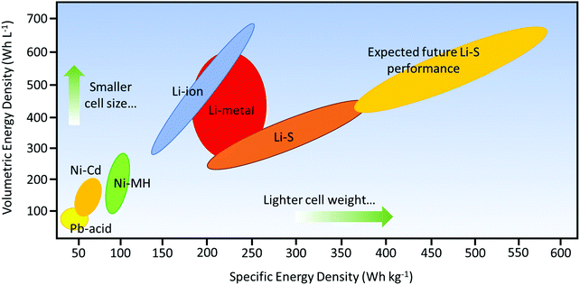 | ||
| Fig. 1 Ragone plot comparing different rechargeable battery technologies as a function of specific and volumetric energy densities. The anticipated driving range is referenced by a minimum specific energy density of 500 W h kg−1 or above. Information obtained from Hagen et al.9 | ||
Electrochemistry of Li–S batteries
As an electrochemical storage device, electrical energy is stored within the sulfur cathodes of Li–S batteries. The usual configuration of a Li–S battery consists of a lithium metal anode, a sulfur-containing cathode composite, an organic electrolyte, and a polymer-based separator to prevent contact between the two electrodes (Fig. 2a). A Li–S cell typically starts with a discharge process since sulfur is in the charged state. During the discharge process, lithium ions (Li+) and electrons are produced through the oxidation of lithium metal at the anode (negative electrode). Subsequently, Li+ move to the cathode (positive electrode) through the electrolyte and the separator within the cell. The electrons, on the other hand, go through the external electrical circuit to reach the cathode end; thus, an electrical current is generated. At this stage, sulfur is reduced to produce Li2S by accepting Li+ and electrons at the cathode. The oxidation reaction during discharge is shown below:| 2Li → 2Li+ + 2e− | (1) |
| S + 2Li+ + 2e− → Li2S | (2) |
| 2Li+ + S → Li2S | (3) |
| Li2S → S + 2Li+ + e− | (4) |
The mechanism of polysulfide dissolution shows the clear distinction between the electrochemistry of LIBs and Li–S batteries. For Li–S batteries, the active material (sulfur) goes through a series of complex reactions forming a variety of end products (i.e. lithium polysulfides). For LIBs, only Li+ ions move between two electrodes where they intercalate/de-intercalate in either anodes or cathodes. Thus, no irreversible reaction mechanism or a significant change in states of matter is observed. Moreover, there is no significant loss of active material into the electrolyte within LIBs. However, since a typical Li–S battery relies on a considerable, if not full, dissolution of the intermediate polysulfides into the electrolyte, unwanted side-reactions occur which consume the active material and cause detrimental electrochemical effects on the overall performance of Li–S batteries. The following will be divided into two sections discussing the intrinsic issues and practical limitations associated with the mechanism of Li–S batteries.
Intrinsic issues of Li–S batteries
Despite the potential advantages of Li–S batteries, there are several intrinsic issues that need to be resolved for performance stability and commercialization:(1) Sulfur is an insulating material (electrical conductivity of ∼10−30 S cm−1), which leads to poor utilization of the active material and restricts electron transfer during the charge/discharge process.2,3,13
(2) During the discharge process, Li reacts with sulfur to form higher-order soluble polysulfides at the cathode, which creates shuttling of polysulfide back and forth between the anode and cathode during the cycling process. The shuttle effect increases the internal resistance of the battery and is considered one of the main causes of capacity fading.14–17 Moreover, the conversion of sulfur to a series of polysulfides involves structural and volumetric changes. The repeated volume variations would eventually compromise the structural integrity of a cathode and restrict sulfur utilization.
(3) The formation of lithium dendrites resulting from the uneven deposition of Li causes safety problems at higher C-rates and the continuous evolution of a porous Li metal structure, which leads to the corrosion of the Li metal.18–21
(4) The formation of an unstable solid electrolyte interface (SEI) layer due to the use of Li anodes22–24 lowers the cell's efficiency and accelerates the capacity fading that compromises the overall performance of Li–S batteries. In addition, the “shuttle effect” within the Li–S system induces the precipitation of insoluble Li2S on the anode, which increases the cell impedance and accelerates active material loss.25–27
Limitations of Li–S batteries for practical application
In addition to the intrinsic issues, the useful energy density and the commercial development of Li–S batteries are still far from satisfactory. This is primarily due to a disconnection between the fundamental research and the commercial requirements. In fact, research has mainly focused on solving the intrinsic hurdles of Li–S batteries, such as the shuttle effect of polysulfides, cathode volume changes, anode stabilization, and sulfur conductivity, particularly in order to obtain valuable electrochemical results. However, those results do not highlight that their focus is on low energy densities, which make them unsuitable for practical applications. To achieve a high energy density, areal sulfur loading in the cathode should be maximized while the weight of inactive components in the cell (e.g., current collectors and electrolytes) should be minimized. In general, a high loading amount of sulfur must be considered to achieve a specific energy density that is greater than that of currently available LIBs. The LIBs offer an areal capacity of 4 mA h cm−2 for the current use in portable electronics and electric vehicles.28 Considering the fact that the average voltage of Li–S batteries (∼2.2 V) is much lower compared to that of LIBs (∼3.5 V), the areal capacity of a Li–S battery needs to be at least 6 mA h cm−2 to compete against the current LIBs. As an example, the sulfur loading amount of 5 mg cm−2 with a sulfur utilization of about 80% can equal the areal capacity of 6.7 mA h cm−2. Indeed, a statistical analysis of recent publications (2015–2019) shows that about 48% of the cathodes use less than 2 mg cm−2 while the remaining ∼30 have a loading amount of more than 4 mg cm−2 (Fig. 3a). This indicates the increasing awareness and the importance of maximizing the content of sulfur. However, the majority of publications have reported the excessive use of the electrolyte, which corresponds to the electrolyte to sulfur (E/S) ratios of more than 10 μL mg−1 (Fig. 3b). This translates to an underwhelmingly low energy density of 100 W h kg−1, which is comparatively lower than the energy densities of 150–250 W h kg−1 for LIBs.29–31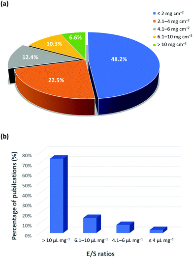 | ||
| Fig. 3 Statistical analysis of publications on (a) areal sulfur loading and (b) E/S ratio (based on 150 articles published during 2015 to 2019).12,32 | ||
Without a doubt, the Li–S battery is a complex device and its useful energy density is influenced by all the above-mentioned issues and limitations, which are highly dependent on the interactions between each active component, i.e., cathode, anode, and electrolyte. Thus, the problems that prevent the commercial success of Li–S batteries require innovative solutions using nanoscience and nanotechnology that can directly address the interfacial aspects of the cell's chemistry and maximize the overall energy densities. It would therefore be of great value to present a comprehensive review of how advances in nanotechnology and theoretical studies of the Li–S system help to overcome the intrinsic hurdles of the Li–S batteries. While several review papers have already summarized the recent advancements in Li–S batteries with some promising electrochemical results, many have failed to capture the disconnection between state-of-the-art performance results and the real-world practical requirements. In this review, we present how each of the nanoengineered components for Li–S batteries meets the benchmark of practical parameters including: high sulfur loading (>4 mg cm−2), lean electrolyte to sulfur ratio (<10 μL mg−1), and high cyclability (>300 cycles).28 Furthermore, we provide our perspectives on the future development of Li–S batteries by the advancements in nanoengineering so that they can enter and penetrate the market of high energy density and rechargeable storage systems. An overview of this review is schematically illustrated in Fig. 4.
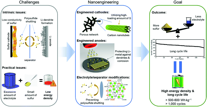 | ||
| Fig. 4 Overview of nanoengineering the components of Li–S batteries to resolve their intrinsic and practical limitations. | ||
II. Nanoengineered cathodes
One of the biggest restrictions with sulfur as a cathode is its very low electronic conductivity (on the order of 5 × 10⁻³⁰ S m−1), which prevents its direct use as an electrode in Li–S batteries.33,34 Thus, low-weight and electrically conducting materials including carbon and conducting polymers must be used as a conductive framework to accommodate and to efficiently utilize sulfur particles for the electrochemistry of Li–S cells.35–38 The conducting network must also possess a high surface area with a porous structure for the efficient adsorption of polysulfides and for the prevention of polysulfide dissolution into the electrolyte to complete electrochemical reactions. In the last decade, many sulfur cathodes have been tailored with carbon structures, binders, and conducting agents to approach the theoretical capacity of sulfur (1672 mA h g−1) and to boost the sulfur utilization with maximum current density.39–41For commercial applications of Li–S batteries, the energy density (W h kg−1) must be greater than that of Li-ion batteries which require a higher loading amount of sulfur and high areal capacity. Here, the gravimetric and volumetric energy densities are determined by the following equations:
 | (5) |
 | (6) |
| Areal capacity (mA h cm−2) = (CT × sulfur utilization × sulfur loading/1000) | (7) |
Thus, this section will only include research papers that exceed (or possibly match) the benchmark: a minimum areal density of 4 mg cm−2 with at least 4 mA h cm−2 areal capacity and 70% sulfur utilization. To obtain a high loading amount of sulfur within the cathode, a new design of electrode and a new conducting electrode material need to be explored for accommodation of the active species (sulfur) without much compromise in the conductivity of the electrode. The cathode also needs modification utilizing conductive additives and binders, and multi-layer and three-dimensional (3D) electrode structures for high sulfur loading. Therefore, this section focuses on: (1) utilizing sulfur composites with nanostructures such as carbon nanotubes and graphene, (2) regulating polysulfide conversion catalysis in cathodes, (3) accommodating volume expansion and high sulfur loading at cathodes, and (4) exploring new architectures of 3D nano-porous structures for higher sulfur loading amounts.
Utilizing sulfur composite with nanostructures
Sulfur composite cathodes consisting of elemental sulfur with conductive materials such as carbon or a conductive polymer have been studied for over 10 years to overcome the problem of sulfur utilization and low conductivity of sulfur. However, there still remains numerous challenges to developing an appropriate cathode configuration that can accommodate a large loading amount of sulfur (>4 mg cm−2) and retain stable electrochemical performance for long cycles. Qie et al. fabricated a layer-by-layer cathode (with six layers of carbon nanofibers) to maximize the sulfur loading amount up to 11.4 mg cm−2, which constitutes about 56.3 wt% of sulfur content.47 The cell demonstrated a high areal capacity of 11.4 mA h cm−2 at 0.1 C-rate, which is more than twice those of commercial LIBs. Zhou et al. developed flexible graphene foam cathodes to obtain a high sulfur loading amount of 10.1 mg cm−2.48 The cathodes achieved the initial specific and areal capacities of 1000 mA h g−1 and 13.4 mA h cm−2, respectively. The high sulfur loaded graphene electrodes offered a reversible capacity of ∼450 mA h g−1 with a cycling stability of up to 1000 cycles. Chung et al. produced a hierarchical cathode that utilized the active material (sulfur/super P carbon/PVDF) in between a carbon film and an aluminum-foil current collector.49 This hierarchical cathode with sulfur loading amounts of 4.2, 6.3, 8.3, and 10 mg cm−2 offered specific discharge capacities of 1242, 1201, 935, and 755 mA h g−1, respectively. Additionally, the capacity decay rate was on the order of 0.04–0.08% per cycle throughout the cycle life of 500 to 1000 cycles, which was attributed to the trapping of polysulfides. Kim et al. designed a modified high sulfur loading electrode (MHSE) which was composed of three entities: a scaffold containing N-doped acetylene black (AB) and N-doped multi-walled carbon nanotubes (MWCNTs), a chitosan binder, and N-doped MWCNTs with a carbon film (NCF).50 This unique structure exhibits a sulfur loading amount of 10 mg cm−2 in the cathode, which manifested an initial specific discharge capacity of 1332 mA h g−1 at 0.1 C-rate with a capacity retention of ∼90% after 50 cycles. The N-doped AB and MWCNT bonded well with sulfur through functionalized carbon that suppressed the polysulfide shuttle reaction within the cathode. It should be noted that all sulfur particles do not participate in the electrochemical reactions during the initial few cycles; as a result, sulfur activation requires a sufficient amount of time to fully transform elemental sulfur into intermediate lithium polysulfides and finally into Li2S2/Li2S (solid–liquid–solid). Furthermore, the E/S ratio has a significant impact on the cyclability and energy density of Li–S cells. For example, an E/S ratio of 6 suggests that the amount of electrolyte will be six times the sulfur amount. Therefore, achieving a high energy density is only possible with a low E/S ratio.Furthermore, Fang et al. synthesized highly porous graphene with a pore volume of 3.51 cm3 g−1 to confine sulfur into the structure obtaining 80 wt% S exhibiting an initial specific capacity of 1500 mA h g−1 and an areal capacity of 7.5 mA h cm−2.51 It is to be noted that different sulfur loading amounts also imply different E/S ratios, which is also crucial for the commercial progress of Li–S batteries. Unless the amount of electrolyte is kept at its minimum, the high sulfur content and areal capacity with effective sulfur utilization will not necessarily mean that the cell will offer a high energy density. Indeed, the electrolyte content is greatly influenced by the sulfur utilization, cycling stability, and coulombic efficiency because the polysulfide can be dissolved in organic solvents used in the Li–S batteries.52,53
McCloskey et al. have demonstrated that as the sulfur loading increases, the energy density reaches an asymptotic limit for a given E/S ratio.53 Considering the ideal case with 100% sulfur utilization (1672 mA h g−1), an E/S ratio of 11 μL mg−1 is the maximum limit for Li–S batteries to compete with commercially available LIBs. The cell's energy densities (both gravimetric and volumetric) with different sulfur loading amounts as a function of the E/S ratio are illustrated in Fig. 5. In the ideal case of 100 wt% sulfur with 100% utilization (Fig. 5a), the E/S ratio cannot be greater than 7 and the sulfur loading amount has to be more than 4 mg cm−2 in order to compete with the specific energy of the current LIBs. In Fig. 5b, a more realistic case is presented with 75 wt% sulfur and 80% utilization, which suggest that the sulfur loading amount has to be at least 7 mg cm−2 for an E/S ratio of 4 when pure or protected Li is used as the anode. Additionally, the sulfur loading amount has to exceed at least 12 mg cm−2 for an E/S ratio of 6.
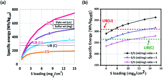 | ||
| Fig. 5 Comparison of specific energy (W h kgcell−1) of LIBs and Li–S batteries. Li–S cells with (a) 100 wt% sulfur at 100% utilization and with (b) 75 wt% sulfur at 80% utilization with different E/S (μl mg−1) ratios. The energy densities were determined from eqn (5)–(7). (a) Reproduced with permission from ref. 42. Copyright 2015, American Chemical Society. | ||
Regulating lithium polysulfide conversion catalysis in cathodes
As explained in the previous section “Electrochemistry of Li–S batteries”, the discharge reaction of Li–S batteries involves the reduction of α-S8 to soluble Li2S8 (HOLPs). This corresponds to an upper plateau region between 1 and 2, producing a thermodynamic discharge voltage of 2.49 V (Fig. 6a).54 The insoluble polysulfide complexes are formed by further reduction of HOLPs to LOLPs which corresponds to region 3 with an average discharge potential of 2.36 V. The evolution process for polysulfides from the HOLPs to LOLPs occurs from the molecule and nanosized clusters to the solid phases.54 The summary of the corresponding phase diagram for lithium polysulfides is given in Fig. 6b. The bottom of the convex hull is occupied by Li2S, Li2S6, and Li2S8 suggesting possible thermodynamically stable intermediate states. Other phases are unfavorable in nature. However, Li2S4 and Li2S2 exist very close to the convex hull and are therefore considered as the metastable intermediates during discharge reactions;55 the optimized structures for lithium polysulfides are summarized in Fig. 6c.56 As shown in Fig. 6d, the stability in formation energy gets drastically reduced for the LOLPs.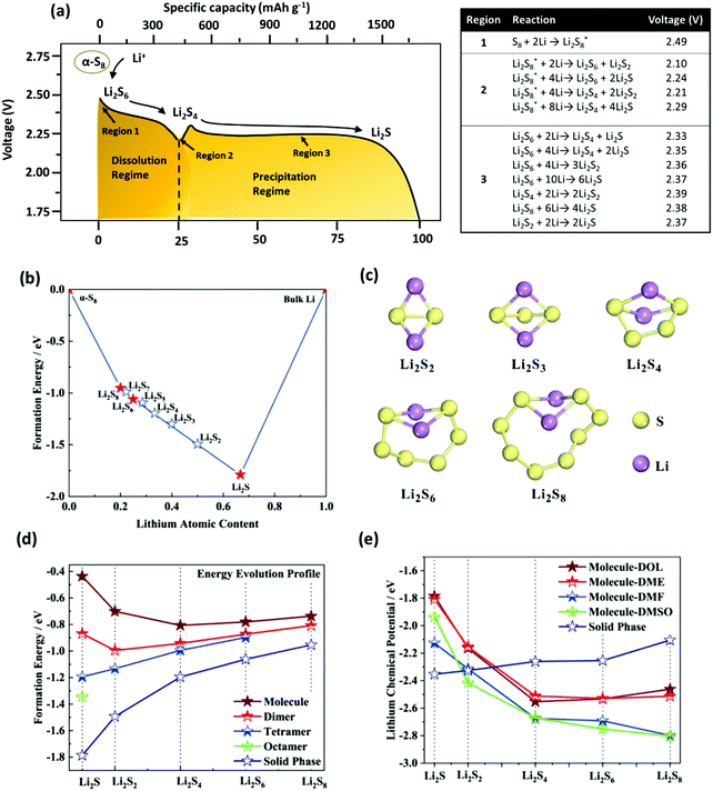 | ||
| Fig. 6 (a) Schematic illustration of the discharging profile, corresponding thermodynamic reaction mechanisms in different regions and resulting voltage for the Li–S battery. (b) Phase diagram for polysulfide phases. (c) Optimized structures of Li2Sn (n = 2, 3, 4, 6, 8). (d) Formation energy evolution profile of different polysulfide phases. (e) Evolution of lithium chemical potential for dissolved polysulfide molecules in different electrolytes and polysulfide solid phases. (a, b, d and e) Reproduced with permission from ref. 54. Copyright 2019, American Chemical Society. (c) Reproduced with permission from ref. 56. Copyright 2015, American Chemical Society. | ||
Evidently, the stability of the Li2S and Li2S2 structures can be greatly improved by the formation of nanosized clusters in solid phases. Also, solid state Li2S8 with a porous long S8 chain is more likely to dissociate in a molecular crystal by dissolving in the electrolytes. Furthermore, the evolution of the lithium chemical potential in different electrolytes shows that the LOLPs, such as Li2S and Li2S2, are thermodynamically more stable in the insoluble solid state, as compared to the soluble molecules or the nanocluster state (Fig. 6e); additionally, a moderate dissolution tendency is observed for Li2S4 and Li2S6. For Li2S8, on the other hand, it shows the highest solubility behavior. This is the reason why the HOLPs tend to dissolve in electrolytes, while the LOLPs tend to precipitate back forming the solid clusters.57,58 However, the dissolution of the HOLPs would eventually migrate towards the Li anode, commonly known as a shuttle effect.55 This results in a series of unfavorable side-reactions causing the performance degradation of the Li–S battery. Hence, a significant amount of research has been focused on the immobilization of soluble polysulfides near cathodes using physical and chemical confinements.59 The physical confinement of the polysulfides is obtained by designing a specialized structure for the cathode to prevent the shuttle effect. The chemical confinement includes designing polar surfaces for polysulfide attraction using heteroatomic doping, addition of redox active entities to stabilize polysulfides or use of catalytic materials to accelerate the reaction of soluble to insoluble polysulfides to prevent the diffusion process.
This section is focused on the chemical confinement of lithium polysulfides and their interactions with the non-metallic and metallic elements, when used in the cathodes. These elements can also act as a catalyst and accelerate the polysulfide conversion reactions to enhance the performance of Li–S batteries.
As shown in Fig. 6c, the soluble HOLPs including Li2S4, Li2S6, and Li2S8 exist in a molecular form with an unstable structure and with high polarity. Therefore, these polysulfides can easily interact with other polar molecules including non-metallic and metallic elements, which act as polysulfide anchors in the cathode. The host polar material can either be bonded to S or Li or both to immobilize polysulfides and to prevent the shuttle effect.
In the structured carbon cathodes, the chemical adsorption of polysulfides can be enabled by doping the non-metallic heteroatoms such as nitrogen, oxygen, fluorine, chlorine, or boron or by introducing functional groups such as amine, esters, imides, ketones or thiols.60–64 The calculated binding energies for different non-metallic chemical classes are summarized in Fig. 7. The adsorption energies of Li2S, Li2S2, Li2S4 and Li2S8 on pristine graphene are −0.41 eV, −0.19 eV, −0.08eV and −0.17 eV, respectively.65 However, a graphene structure with vacancy or reduced graphene oxide with –OH, –COOH and epoxy functional groups increases the polarity in the carbon structure and improves polysulfide binding.66,67 Liang et al. have studied the interaction of graphene oxide with Li2S4 using XPS analysis and observed 20% reduction of the C–O(H) bond to the C–C bond as well as the formation of the graphene–Li2S4 bond, which suggests lithium polysulfide interactions with the surface oxy groups in graphene oxide.68 Doping N or B by replacing a carbon atom introduces negatively or positively charged centers, respectively, to adsorb a cation or an anion from the structure of polysulfides limiting their unnecessary diffusion.69,70 On the other hand, Seh et al. have studied the concept of different functional groups and their effect on polysulfide adsorption using different binders for fabricating cathodes (Table 1).71 The study suggests that ![[double bond splayed left]](https://www.rsc.org/images/entities/char_e009.gif) C
C![[double bond, length as m-dash]](https://www.rsc.org/images/entities/char_e001.gif) O groups commonly found in polyvinyl pyrrole can exhibit higher binding to lithium polysulfides (1.14 and 1.3 eV with Li2S2 and Li2S, respectively) when used as a binder for cathode fabrication. Similarly, introducing conductive polymers such as polyaniline, polypyrrole and poly(3,4-ethylenedioxythiophene) with heteroatoms such as oxygen, sulfur or nitrogen can assist in the stable binding of the polysulfides to the cathode.72 Also, non-metallic elements present promising characteristics for polysulfide adsorption and their capabilities for ultra-high sulfur loading in practical application can be exploited by nano-engineering (detailed in later sections).
O groups commonly found in polyvinyl pyrrole can exhibit higher binding to lithium polysulfides (1.14 and 1.3 eV with Li2S2 and Li2S, respectively) when used as a binder for cathode fabrication. Similarly, introducing conductive polymers such as polyaniline, polypyrrole and poly(3,4-ethylenedioxythiophene) with heteroatoms such as oxygen, sulfur or nitrogen can assist in the stable binding of the polysulfides to the cathode.72 Also, non-metallic elements present promising characteristics for polysulfide adsorption and their capabilities for ultra-high sulfur loading in practical application can be exploited by nano-engineering (detailed in later sections).
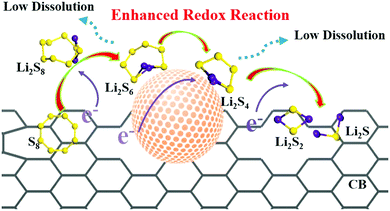 | ||
| Fig. 7 Schematic for enhanced reaction kinetics and reduced polysulfide dissolution using nano-catalysts in the Li–S battery. Reproduced with permission from ref. 73 Copyright 2018, Elsevier. | ||
Apart from surface adsorption or anchoring, another approach for improving the stability of the Li–S battery and minimizing the polysulfide dissolution is to accelerate their transformation from soluble HOLPs to insoluble LOLPs or to introduce a redox mediator to stabilize the soluble HOLPs.5,74 The addition of metallic compounds such as metal oxides, metal nitrides and metal sulfides in cathodes can result in completely independent reaction chemistry in the Li–S battery. Based on the Wackenroder reaction, the introduction of metal oxide complexes can introduce an additional set of reactions resulting in the formation of polythionates.75 A few metal oxides such as VO2, CuO, MnO2, V2O5 and NiOOH whose redox potentials lie between 2.4 V < E° ≤ 3.05 V, just above the redox potential window of soluble polysulfides can promote a polythionate reaction.76 Graphene oxide can also be included in this category of materials with a redox potential range of ≥2.4 V.68 These materials can strongly inhibit polysulfide diffusion in the electrolyte and play a key role in stabilizing the capacity for a longer life cycle of the Li–S battery. The summary of a few well-known metal oxide complexes with their redox activity to form thiosulfate and sulfate is shown in Fig. 8. Apart from them, other metal oxides such as Al2O3, Fe2O3, Co3O4, NiO and CoO are also used to act as a polysulfide anchor. Due to the inferior electronic conductivity of metal oxides, they are coated uniformly on some conductive carbon substrates to allow post-diffusion on the conductive surface. As compared to non-metallic elements, metallic compounds show a relatively higher polysulfide binding energy and efficient polysulfide trapping.77 The polysulfide binding energies for different metal oxides, carbides, nitrides and sulfides are summarized in Table 2.
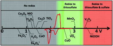 | ||
| Fig. 8 Chemical reactivity of different metal oxides with lithium polysulfides in redox potential versus Li/Li+, superimposed with a typical Li–S cyclic voltammetry curve. Reproduced with permission from ref. 76. Copyright 2015, John Wiley & Sons. | ||
| Metal oxides | Adsorption energy (Li2S, eV) | Adsorption energy (Li2S8, eV) | Li diffusion barrier (eV) | Ref. | Metal nitrides/carbides | Adsorption energy (Li2S, eV) | Adsorption energy (Li2S8, eV) | Li diffusion barrier (eV) | Ref. |
|---|---|---|---|---|---|---|---|---|---|
| Al2O3 | 7.12 | 3.54 | — | 77 | VN | 2.75 | 2.93 | — | 85 |
| CeO2 | 6.33 | 2.07 | — | 77 | Co4N | 7.14 | 9.67 | — | 90 |
| MgO | 5.71 | 1.87 | — | 77 | TiN | Li2S4 = 3.28 | 4.69 | — | 84 |
| La2O3 | 5.85 | 2.18 | — | 77 | InN | Li2S4 = 1.57 | Li2S6 = 1.79 | — | 90 |
| CaO | 5.49 | 1.54 | — | 77 | MnN | Li2S4 = 2.04 | 2.01 | — | 91 |
| Mn3O4 | Li2S2 = 1.22 | Li2S6 = 1.84 | — | 84 | CrN | Li2S4 = 2.78 | 2.90 | — | 91 |
| Co3O4 | 5.32, 4.89 | 5.00 | — | 84 | TiN | Li2S4 = 2.86 | 2.89 | — | 91 |
| VO2 | 4.55 | 2.62 | — | 85 | ScN | Li2S4 = 2.68 | 2.77 | — | 91 |
| V2O5 | 4.22 | 3.66 | — | 85 and 86 | TiC | — | Li2S6 = 2.32 | — | 92 |
| TiO2 | 1.96 | 0.81 | — | 87 | W2C | — | Li2S6 = 2.57 | — | 92 |
| Ti4O7 | 3.49 | Li2S4 = 4.08 | — | 88 | Mo2C | 4.89 | 8.20 | — | 92 and 93 |
| MoO3 | 3.82 | 2.00 | — | 86 |
| Metal sulfides | Adsorption energy (Li2S, eV) | Adsorption energy (Li2S8, eV) | Li diffusion barrier (eV) | Ref. | Metal sulfides | Adsorption energy (Li2S, eV) | Adsorption energy (Li2S8, eV) | Li diffusion barrier (eV) | Ref. |
|---|---|---|---|---|---|---|---|---|---|
| ScS | 1.68 | — | 0.10 | 79 | CoS2 | Li2S2 = 1.77 | Li2S6 = 1.01 | 0.12 | 86 and 94 |
| TiS | 4.33 | — | 0.37 | 79 | SnS2 | — | Li2S6 = 0.80 | 0.26 | 88 |
| VS | 4.89 | — | 0.22 | 79 | ZrS2 | 3.20–3.50 | 1.00–1.15 | — | 80 |
| CrS | 4.26 | — | 0.27 | 79 | WS2 | 1.45 | 0.52 | — | 96 |
| MnS | 2.50 | — | 0.33 | 79 | MoS2(Mo-edge) | 4.48 | — | ∼0.8 | 97 and 99 |
| FeS | 3.52 | — | 0.20 | 79 | MoS2(S-edge) | 2.70 | — | 0.47 | 97 and 99 |
| CoS | 2.71 | — | 0.37 | 79 | MoS2(terrace) | 0.87 | — | — | 97 |
| NiS | 2.46 | — | 0.32 | 79 | MoS2−x | Li2S4 = 4.12 | 0.54 | 99 | |
| CuS | 2.18 | — | 0.17 | 79 | NbS2 | 3.20–3.50 | 1.20–1.50 | 99 | |
| ZnS | 2.76 | — | 0.63 | 79 | Ni3S3 | — | Li2S6 = 0.72 | 0.24 | 86 |
| VS2 | 3.00–3.30 | Li2S6 = 1.04 | 0.12 | 80 and 86 | Ni3S2 | Li2S4 = 4.52 | Li2S4 = 4.39 | — | 94 |
| TiS2 | 2.90–3.20 | Li2S6 = 1.02 | 0.18 | 80 and 86 | Co9S8 | 5.51 | 6.08 | — | 98 |
As summarized in Table 2, a few catalysts such as Co4N possess relatively higher binging energies (Li2S8 = 9.67 eV) such that Li–S bonds can be easily broken resulting in the partial sulfurization of the metallic surface compromising their use as a polysulfide anchor.78 However, binding energy alone cannot be considered as an important criterion for designing catalysts for polysulfide transformation. Surface diffusion also plays a significant role in the uniform growth of Li2S. For this reason, the Li-ion diffusion barrier is considered as an ideal descriptor for analyzing the surface properties of the catalysts. A lower diffusion barrier suggests faster diffusion, which results in a relatively unhindered intercalation/deintercalation reaction and thereby accelerates the polysulfide conversion. This diffusion is dependent upon the transition state points of the metal composites. Unlike metal oxides as sulfur hosts, transition metal sulfides exhibit higher electronic conductivities due to the covalent bonding nature with S2−/S22− ions.79 Higher density of states in metal sulfides allow transition metals to act as the binding sites for extrinsic adsorbates, which permits facile diffusion of Li ions and improves the overall kinetics. Such materials can enhance the structural aspects of the host sulfur electrodes where higher sulfur loading needs to be achieved for practical application of the Li–S battery. For example, Manthiram and coworkers designed freestanding 1T MoS2/graphene heterostructures as efficient polysulfide catalysts for Li–S batteries.80 The cell fabricated with 10 mg cm−2 sulfur in the cathode exhibits a high reversible capacity of 1181 mA h g−1 and a high capacity retention of 96.3% after 200 cycles at 0.1C. Similar cells upon prolonged cycling of 500 cycles at 1C showed a low capacity decay of only 0.08% per cycle and maintained an areal capacity of over 4.5 mA h cm−2. The improved performance of the Li–S battery with a higher sulfur loading is therefore due to the efficient catalytic activity in the polysulfide transformation of the 1T MoS2/graphene structure.
A similar approach has been carried out by Wang et al. where a free-standing structure of VS4 was combined with carbon nanotubes (CNTs).81 CNTs provide high electrical conductivity, while nanostructured VS4 assists in trapping and converting polysulfides to prevent parasitic reactions leading to the degradation of Li–S cells. The cathode can accommodate a high areal density of the order of ∼13 mA h cm−2 to deliver a respectable energy density of 243.4 W h kg−1. Ogoke et al. have developed transition metal decorated graphene nanotubes (M-GNTs) embedded in sulfur cathodes.82 The cathode exhibited a sulfur loading of 4.5 mg cm−2 and delivered a discharge capacity of 1234.7 mA h g−1 at 0.05C. This demonstrates a synergistic effect of the electrocatalyst (efficiently converting long to short chain polysulfides) and GNTs (providing high electrical conductivity) for an excellent electrochemical performance.
Zhou et al. have developed a twin heterostructure containing TiO2–TiN embedded into the graphene/sulfur cathode.83 TiO2 has a high adsorption affinity towards lithium polysulfides, while TiN provides efficient conversion of insoluble Li2S. The synergistic effect of TiO2 and TiN helps in faster diffusion and entrapment of polysulfides; moreover, the cathode with a sulfur loading amount of 4.3 mg cm−2 delivers a specific capacity of 800 mA h g−1 at 1C. When considering a catalyst system for Li–S batteries, it is crucial that the cathodes exhibit high ion/electron conductivities with sufficient surface area for effective migration and conversion of lithium polysulfides. Evidently, nanoengineering can play a critical role by providing the 2D and 3D materials with large interconnected networks to improve the catalytic efficiency of the reactions. Additionally, the cost of catalysts is another important issue to consider to achieve scalable manufacturing of Li–S batteries.
Nanoengineering for accommodating the volume expansion of sulfur
Sulfur as an active cathode material undergoes a volumetric expansion during cycling due to the phase transformation from the orthorhombic α-sulfur to cubic Li2S (Fig. 9). Based on the densities of sulfur (2.07 g cm−3) and Li2S (1.66 g cm−3) at room temperature, the volume is expected to expand to about 80% during the phase transition.100 The repeated volume variation of sulfur restricts the pore space for electrolyte adsorption; furthermore, the expansion of the electrode makes more room for parasitic precipitates, which leads to the pulverization of the cathode and the detachment of sulfur from a conducting matrix.101 The isolated sulfur particles do not participate in the electrochemical reaction, resulting in a low sulfur utilization and a fast capacity decay. In this regard, the conducting network should accommodate the volumetric expansion of the active material and retain the structural integrity of the cathode. The low density of sulfur will not result in high volumetric energy density of the cell compared to LIBs. Therefore, the balance between the volumetric energy density and performance needs to be considered while controlling the porosity of the cathode structure.102,103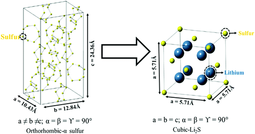 | ||
| Fig. 9 Crystal structures representing the phase transformation of the orthorhombic-α sulfur to the cubic lithium–sulfide (Li2S). Reproduced with permission from ref. 101. Copyright 2015, American Chemical Society. | ||
Barai et al. have developed a computational method to study the issue of volume expansion in Li–S batteries.104 The computational model in Fig. 10a suggests that during the dissolution of sulfur (S8) particles, the internal pressure of the electrolyte decreases and the external pressure remains constant. To maintain a chemical equilibrium within the cell, the carbon network deforms inwards to release the external pressure. During the precipitation of Li2S, the internal pressure of the electrolyte increases with reference to the external environment. Therefore, the carbon structure expands to accommodate the mechanical forces accordingly. Based on the model, the magnitude of the pressure can be proportionally correlated with the volumetric strain induced during the dissolution/precipitation of sulfur (Fig. 10b and c).
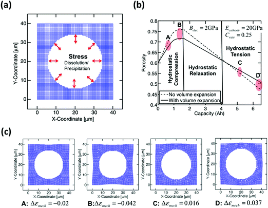 | ||
| Fig. 10 (a) Computational modeling of compressive and tensile hydrostatic stress on the pore walls. (b) Morphological variation of pores with galvanostatic charge/discharge capacity. (c) The points A, B, C, and D shown in Fig. 8b correspond to the shape of the pore during medium (A) and large (B) compression and medium (C) and large (D) tension, respectively. Reproduced with permission from ref. 104. Copyright 2016, Elsevier. | ||
Furthermore, the critical issue concerned with the confinement of a higher sulfur loading amount is the low pore volume of the micro/mesoporous carbon host structure. The sulfur content in the carbon structure can be related to the pore volume as given by the following equation:
 | (8) |
Exploring 3D nano-porous structures
The conventional metal-foil current collectors (i.e. aluminum) are not only susceptible to corrosion during the charge/discharge cycle but also incapable of directing channels for electron/ion throughout the cathode structure. Thus, sulfur eventually loses the electrical contact with the conductive network, which gradually increases the internal resistance of the battery. A three-dimensional framework has been proposed as a current collector that can provide efficient paths for ions and electrons and yield high sulfur utilization even at higher loadings. It is therefore critical to find a 3D nano-porous structure which can act as a host-structure for cathode materials as well as a current collector. Ruopian et al. prepared a hollow carbon fiber foam (HCFF) and used it as a 3D current collector to accommodate a high amount of sulfur.105 The cell exhibited a high areal capacity of 12 mA h cm−2 after 150 cycles with a capacity retention of 70% at a sulfur loading of 21.2 mg cm−2. Choi and co-workers fabricated a binder-free 3D CNT/sulfur composite, where 3D CNTs were used as a current collector and as a conductive scaffold to accommodate a large loading amount of sulfur of up to 8.33 mg cm−2.106 It exhibited areal and specific capacities of ∼8.8 and 1068 mA h g−1, respectively, at a current density of 1.4 mA cm−2. Lu et al. designed cathodes by embedding sulfur into porous graphene sponges (S-GS).107 The areal sulfur loading of such cathodes was around 12 mg cm−2, which delivered a specific capacity of 416 mA h g−1 at a current density of 2 mA cm−2 (0.1 C-rate). Moreover, the cell demonstrated excellent cycling stability with a capacity decay rate of 0.08% per cycle after 300 cycles. Li et al. developed a strategy to incorporate a high amount of sulfur into CNT foams by the sulfur vapor infiltration technique followed by mechanical compressing.108 The electrodes accommodated a mass loading of 19.1 mg cm−2 sulfur which delivered areal and specific capacities of 19.1 mA h cm−2 and 1039 mA h g−1, respectively. Zeng et al. constructed a nano-structured CS@CTAB/ABS (carbon–sulfur@cetyltrimethyl ammonium bromide) + CNT electrode by the blade casting technique with a mass loading of 6.7, 8.9, and 11.1 mg cm−2, which delivered specific capacities of 1179 mA h g−1 (@100 mA g−1), 1078 mA h g−1 (@100 mA g−1), and 1011 mA h g−1 (@783 mA g−1), respectively.109 However, this cathode in Li–S cells could not sustain more than 50 cycles. Shaibani et al. developed an expansion-tolerant cathode which can accommodate natural volume expansion during the charging/discharging process to deliver a high specific capacity of 1440 mA h g−1 at a loading amount of 13 mg cm−2; as a result, the cathode demonstrates 85% sulfur utilization at 0.1C.110A summary of nanoengineered high-sulfur loaded cathodes using various techniques and the outcomes is presented in Table 3. The strategies for the effective utilization of the high-sulfur loaded cathode are still not conclusive and the application of these methods in commercial applications remains unacceptable. Indeed, there is an urgent need to develop a deeper understanding of electrochemical mechanisms within the nano-engineered cathodes for Li–S batteries.
| Cathode type | Areal sulfur loading (mg cm−2) | Initial specific capacity (mA h g−1) | Final capacity (mA h g−1) | C-rate | Cycle number | Ref. |
|---|---|---|---|---|---|---|
| Sulfur sandwiched between two carbon nanofibers | 5.7 | 1187 | 600 | 0.2C | 200 | 47 |
| 11.4 | 995 | 650 | 0.2C | 100 | 47 | |
| Graphene foam electrodes | 10.1 | 1000 | 450 | 1.5C | 1000 | 48 |
| Hierarchical sulfur electrodes | 4.2 | 1242 | 900 | 0.2C | 200 | 49 |
| 6.3 | 1201 | 780 | 0.2C | 200 | 49 | |
| 8.3 | 935 | 700 | 0.2C | 200 | 49 | |
| 10 | 755 | 550 | 0.2C | 200 | 49 | |
| MHSE (N-doped MWCNTs) | 10 | 1150 | 1047 | 1/3C | 50 | 50 |
| Hollow carbon fiber foam (HCFF)/MWCNT–S composite | 6.2 | 1263 | 1000 | 0.1C | 50 | 105 |
| 10.8 | 1066 | 720 | 0.1C | 50 | 105 | |
| 16.5 | 989 | 700 | 0.1C | 50 | 105 | |
| 3D CNTs/S composite | 8.33 | 1068 | 560 | 0.1C | 150 | 106 |
| Graphene sponge (S-GS) | 12 | 416 | 350 | 0.1C | 300 | 107 |
| Sulfur infiltrated CNT foam | 19.1 | 1039 | 500 | 0.1C | 100 | 108 |
| CS@CTAB/ABS + CNTS | 6.7 | 1179 | 890 | 0.08C | 50 | 109 |
| 8.9 | 1078 | 802 | 0.09C | 46 | 109 | |
| 11.1 | 1011 | 783 | 0.05C | 12 | 109 | |
| Free-standing CNF network | 10.5 | 753 | 680 | 0.1C | 100 | 111 |
| CMC binder based composite S cathode | 13 | ∼1200 | ∼1100 | 0.1C | 50 | 110 |
| 11 | ∼1200 | ∼1050 | 0.1C | 100 | 110 | |
| CGCC cathode | 57.6 | 657 | 446 | 0.1C | 100 | 112 |
| 2H MoS2/graphene | 10 | 1050 | 762 | 0.1C | 200 | 80 |
| 1T MoS2/graphene | 10 | 1181 | 1137 | 0.1C | 200 | 80 |
| CoS2-SPAN-CNT | 4.6 | 1413 | 913 | 0.2C | 50 | 113 |
| Ni3S2-N/S co-doped rGO | 5.8 | 574 | 416 | 1C | 200 | 95 |
| S/C/Co3O4 | 8.2 | 890 | 720 | 0.1C | 20 | 114 |
III. Nanoengineered anodes
A long cycle-life for Li-anodes has been reported at the coin cell-level with excess electrolytes (high E/S ratio). However, most of these results cannot be translated into practical cells,9,12,115,116 which requires minimum use of electrolytes (below the E/S ratio of 10). Indeed, the success of practical Li–S batteries lies in a reliable Li anode that can withstand low E/S ratios. Much progress has been made in designing a stable Li metal anode, such as using protective layers to the surface of the Li anode, developing a host structure for Li metal accommodation, and employing an interlayer that acts as a polysulfide barrier. Such key developments in nanoengineered Li anodes are summarized as follows.Protected Li anodes via nanolayer passivation
Introducing a protective layer to the surface of the Li anode has been demonstrated to be a successful approach that not only prevents the corrosion of the Li metal but also circumvents the issue of Li dendrite growths.23,112 One approach is to precisely modify the interface between the anode and the electrolyte using the atomic layer deposition (ALD) process (Fig. 11a). As demonstrated by Kozen et al., the nano-layer of Al2O3 (∼14 nm) can protect the Li metal under challenging conditions.117 When used as an electrode material, the atomic Al2O3 layer effectively suppressed the formation of Li dendrites by facilitating a smooth Li deposition morphology (Fig. 11b).23 Note that the unprotected Li electrode shows a rough and porous morphology which indicates an unstable cycling process. The long-term cycling test with full-cell (Li–S) configurations showed that the Al2O3-coated anodes offset the initial decrease in cell capacity for the first cycle (Fig. 11c and d). The cell also exhibited stable capacity retention for up to 100 cycles with a sulfur loading of ∼5 mg cm−2 and no addition of LiNO3 electrolyte additives.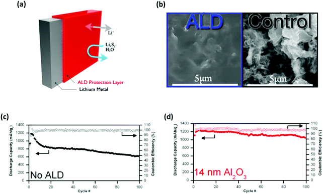 | ||
| Fig. 11 Addressing the intrinsic issues of Li–S batteries using nano-layers of Al2O3. (a) Schematic illustrating the Al2O3 protected Li metal via the ALD process. (b) SEM images comparing the surface morphology conditions between the Al2O3 coated and the unprotected Li electrodes after cycling. The full-cell cycling performance tests comparing the capacity retentions and the corresponding coulombic efficiencies between (c) the unprotected and (d) the Al2O3 coated Li anodes. (a, c and d) Reproduced with permission from ref. 117. Copyright 2015, American Chemical Society. (b) Reproduced with permission from ref. 23. Copyright 2015, American Chemical Society. | ||
As shown by Choi and co-workers, protecting the Li metal with nano-layers could also be accomplished by sputtering two-dimensional molybdenum disulfide (2D MoS2) onto the surface of Li anodes (Fig. 12a).118,119 With the Li-intercalated atomic layer of MoS2 formed, a stable Li electrode position is realized with the nucleation sites for dendrite growth inhibited (Fig. 12b). In addition to the prevention of Li dendrites, an MoS2-protected Li anode (when configured into Li–S full cells) has been demonstrated to prevent porous/dead Li from forming on the surface of the anode while facilitating the reversibility of active materials (Fig. 12c). More importantly, the cells using MoS2 coated Li anodes were characterized with a high sulfur loading of 6 mg cm−2 with a capacity retention of up to 1000 cycles at an E/S ratio of 10 μL mg−1. Evidently, the protective properties of the MoS2 nano-layers minimized the active material loss and facilitated the long-term reversible charge/discharge processes at the practically required level.
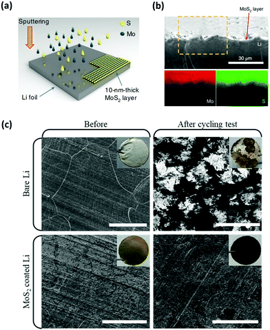 | ||
| Fig. 12 MoS2 nano-layers were used to prevent Li dendrites and polysulfide corrosions. (a) Schematic of the preparation of the MoS2 protected Li anode via the sputtering method. (b) The cross-sectional SEM image and the corresponding EDX elemental mapping of the cycled MoS2 protected Li metal, indicating that the surface of Li is free from dendrite growth. (c) Top-view SEM images comparing the surface morphologies of the unprotected and the MoS2 protected Li anodes before and after symmetric cell tests. Reproduced with permission from ref. 118. Copyright 2018, Springer Nature. | ||
Li metal-free host composed of nanomaterials
Although the Li metal has the advantage of requiring no conductive scaffolds, it undergoes infinite volume changes during the charging/discharging process, which accelerates the depletion of active materials. To resolve the infinite volume change of Li anodes, lightweight and conductive nanomaterials have been employed as hosts for the accommodation of Li metal deposition.120–123 Some of these host materials have been designed for polysulfide protection and for high-sulfur loaded Li–S batteries. In particular, Cai et al. utilized prelithiated germanium (Ge) nanoparticles as the anode, which facilitated the operation of Li–S batteries (sulfur loading of 4.7 mg cm−2) with an initial discharge capacity of 1043 mA h g−1 for over 1000 cycles at 1.0C (Fig. 13a and b).124 Similarly, a prelithiated carbon–silicon nanocomposite was used as an anode and paired against the sulfur–carbon composite cathode.125 This particular set-up delivered a discharge capacity of 300 mA h g−1 within the voltage window of 1.25 to 2.8 V. By taking advantage of the porous structure, 3D graphene networks were employed as support for the lithiated silicon anode (3D lithiated Si-G).126 The full cell composed of this anode and the sulfur copolymer cathode (3D cpS-G) exhibited a stable capacity of 620 mA h g−1 (with the total weight of the anode and cathode accounted for) for up to 500 cycles at a sulfur loading of ∼5 mg cm−2 (Fig. 13c and d). A pure carbon-based host material has been explored as an alternative to the metallic Li anode. Bhargav et al. reported a lithiated meso-carbon/carbon-paper anode with a sulfur loading of 4.3 mg cm−2, which delivered a high sulfur utilization of 1150 mA h g−1 at 100 cycles.127 A carbon composite anode is another example of a metal-free host material for anodes in Li–S batteries. Zhang's group developed a lithophilic LiC6 layered between carbon fibers to form a composite anode for Li–S pouch cells.128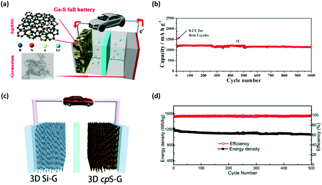 | ||
| Fig. 13 Nanomaterials as the host for the Li metal. (a) Schematic illustrating the full-cell configuration of the lithiated nano-Ge anode and the B,N-Co-doped graphene supported cathode. (b) The cycling performance of the Ge nanoparticles–S full cell at the rate of 1C. (c) Schematic of the lithiated 3D silicon–graphene anode configured into a full cell with the 3D cpS-G cathode and (d) the corresponding long-term cycling performance of the cell at 0.27 A g−1. (a and b) Reproduced with permission from ref. 124. Copyright 2016, American Chemical Society. (c and d) Reproduced with permission from ref. 126. Copyright 2016, Royal Society of Chemistry. | ||
Besides the carbon-based host materials, silicon-based hosts have also been explored to address the fundamental challenges to Li–S batteries. For instance, a Li–S cell configured with a sulfur cathode and a lithiated Si/SiOx nanosphere anode together with a specialized electrolyte (1 M LiTFSI, 0.4 M LiNO3, and 0.05 M Li2S8 in DME/DOL solvent) was demonstrated to reduce the excessive amount of Li metal to achieve an energy density of 497 W h kg−1.129 A ball-milled mixture of silicon nanoparticles (average particle size of 100 nm) dispersed in a solution of lithiated poly(acrylic acid) was prepared as an anode material for Li–S batteries.130 The electrochemical performance of the Li–S cell utilizing such an anode exhibited a discharge capacity of ∼400 mA h g−1 with a sulfur loading of ∼5 mg cm−2.
Nano-interlayer approach for Li anodes
Polysulfides produced during the discharging/charging processes can easily dissolve into the electrolyte and diffuse freely through the separator to react with the Li metal, which can cause the degradation of the anode. This issue becomes more apparent when the areal loading of sulfur is very high. To address this, an interlayer to limit the polysulfide migrations between the Li anode and the S cathode has been proposed. There have been many insightful reviews of the interlayer insertion for Li anodes.17,131–134 To avoid repetition with the previous reviews, this section will focus on the interlayers implemented to Li anodes particularly for high-sulfur loaded Li–S batteries.Interlayers composed of carbon-based nanomaterials are known to enhance the electrochemical stability of Li–S batteries, including graphene films,136,137 multiwalled CNT films,138,139 carbon nanofiber/polyvinylidene fluoride composite membranes,140 nano-porous carbon cloth coated with Al2O3,141 Fe3C/carbon nanofiber films,142 and TiO2/graphene nanocomposite films.143 It is known that carbon interlayers not only act as the barrier against the shuttling polysulfides but also work as the artificial SEI with high Li+ ionic conducting properties to minimize the impedance within the cells. For instance, Huang et al. prepared a lithiated graphite and placed it on the anode side of a Li–S cell (Fig. 14a).135 This interlayer facilitated a constant supply of Li+ ions to reduce the corrosive reactions between the polysulfides and the surface of the Li metal. Another strategy is to implement a multi-layer graphene (MLG) as an interlayer for Li anodes. The MLG interlayer used by Kim et al. not only mitigated the parasitic effects of Li dendrites but also reduced the corrosive reactions between the polysulfides and Li metal (Fig. 14b and c).20 As a result, the Li–S cell with the protection of MLG exhibited an areal capacity of 4.0 mA h cm−2 and a capacity retention of ∼81% after 200 cycles (Fig. 14d). In another case, CNT films with high electrical conductivity, large surface area, and excellent mechanical properties were inserted on both sides of the separator in Li–S batteries (Fig. 15a).144 In this case, the cathode-side CNT film worked as a barrier to suppress the shuttling effect of polysulfides and the anode-side CNT film acts as a buffer layer to prevent the Li dendrite growth (Fig. 15b–g). A full-cell with the CNT interlayers operated under a sulfur loading of ∼4.0 mg cm−2 with an E/S ratio of ∼5 μL mg−1 for up to 150 cycles at 1C (Fig. 15h). It is evident that the advancement in the nano-insertion interlayer to the anode side of Li–S batteries will undoubtedly promote the development of multifunctional membranes that are compatible to both anodes and cathodes.
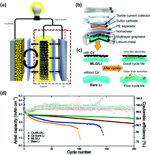 | ||
| Fig. 14 Using an interlayer composed of nanomaterials for Li anode protection. (a) Schematic diagram of the Li–S cell configuration with a lithiated graphite as an interlayer. (b) An illustration of the coin-cell assembly with a multi-layer graphene inserted between the anode and the separator. (c) Graphical representations of either bare or the multi-layer graphene protected anodes before and after cycling. (d) Cycling performance for the Li–S batteries with different interlayer conditions at a current density of 1.0 mA cm−2. (a) Reproduced with permission from ref. 135. Copyright 2014, Springer Nature. (b–d) Reproduced with permission from ref. 20. Copyright 2015, American Chemical Society. | ||
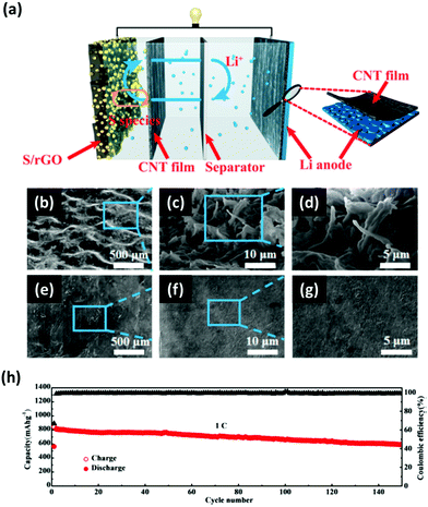 | ||
| Fig. 15 (a) Schematic illustration of the CNT films inserted on both sides of the separator to simultaneously address the polysulfide shuttling and Li dendrite issues. (b–d) The top-view SEM images of the Li anode surface without the protection of the CNT film showing the overgrown Li dendrites. (e–g) The top-view SEM images of the CNT film protected Li metal. (h) Long-term cycling performance of the Li–S cell with CNT interlayers cycled at a C-rate of 1C with a sulfur loading of ∼4 mg cm−2. Reproduced with permission from ref. 144. Copyright 2017, American Chemical Society. | ||
The number of research studies on anodes for Li–S batteries with a lean amount of electrolyte is comparatively smaller than that on cathodes. Nonetheless, utilizing the Li metal as the anode is progressively becoming the bottleneck for the commercialization of Li–S batteries. Thus, the effectiveness of the anodes should be evaluated with respect to their performance under stringent E/S ratios. A summary of nanoengineered anodes for Li–S batteries with an E/S ratio of 10 or less is presented in Table 4.
| Anode type | Areal sulfur loading (mg cm−2) | Specific capacity (mA h g−1) | E/S ratio (μL mg−1) | C-rate | Cycle number | Ref. |
|---|---|---|---|---|---|---|
| Nano-layers Al2O3 coated Li metal | 5 | 1200 | ∼10 | ∼0.1C | 100 | 117 |
| Li anode protected by 2D MoS2 layer | ∼4 | 940 | 10 | 0.5C | 1200 | 118 |
| 3D graphene as host material for Li metal | ∼5 | 620 | ∼8 | ∼0.5C | 500 | 126 |
| Protecting Li anode with CNT films | 4 | 833 | 5 | 1C | 150 | 144 |
| Lithiated MWCNT interface | ∼4 | ∼950 | 5 | 1C | 450 | 145 |
| Lithiated MCMB host | 4.3 | 1150 | ∼7 | 1C | 100 | 127 |
| Li/CF composite anode | ∼7 | 751 | ∼4 | 0.1C | 100 | 128 |
IV. Nanoscale electrolyte modifications
The electrolyte plays an important role in the development of high-performance Li–S batteries; it acts as a mediator for polysulfide distributions and as a pathway for ion transportation within a cell. The ether-based electrolytes are, by far, the most commonly used liquid electrolyte for Li–S cells since they enable high sulfur utilization through the dissolution and re-deposition of polysulfides.146–148 However, they also induce the “shuttle effect” which inevitably impacts the electrochemical performance of high energy-density Li–S batteries. Thus, modifying the electrolyte to directly influence the solubility of polysulfides can bring improvements in the cycling performance as well as safety of the Li–S cells. Here, we discuss liquid-based electrolytes that are specifically tuned to handle the challenging conditions of low E/S ratio and high sulfur loading. Furthermore, nanoengineered solid/gel electrolytes for practical Li–S batteries are mentioned and discussed in brief.Tuning liquid-based electrolytes
Many researchers have examined the possibility of tuning liquid-based electrolytes at the molecular level with additives to suppress the dissolution of polysulfides.149,150 Conveniently, an additive approach can improve the performance of Li–S batteries without altering the existing cell configuration or the electrode materials. For instance, pyrrole and triphenylphosphine additives in ether-based electrolytes are known to induce the formation of an interphase-like layer on sulfur cathodes.55,150,151 Such layers have been found to mitigate the effects of polysulfide dissolution into the electrolyte. Similarly, ether electrolytes that are modified with N-methoxyethyl-N-methyl-pyrrolidinium bis-(trifluoromethanesulfonyl)-imide (Pyr1,201TFSI) have been prepared to facilitate the formation of stable SEI layers on the surface of Li anodes which prevent Li dendrites and polysulfide shuttling.152–154 These electrolyte systems exhibit stable discharge capacities at a rate of 0.1C for up to 100 cycles with the areal loading and an E/S ratio of 4 mg cm−2 and ∼7.5 μL mg−1, respectively. More recently, Nazar's group demonstrated the use of a diethylene glycol dimethyl ether system (G2:LiTFSI) to directly influence the solubility of polysulfides in a liquid electrolyte while simultaneously stabilizing the SEI layer at the anode.155 As a result, a stable specific capacity of 720 mA h g−1 for over 100 cycles was achieved using a low E/S ratio of 5 μL mg−1.Nanoengineered solid/gel-based electrolytes
Although liquid electrolytes have been widely used for Li–S batteries because of their higher ionic conductivity, they still suffer from the inevitable dissolution of polysulfides and safety concerns (e.g. low flash points, high volatility, and potential leakage). Thus, the use of solid-based electrolytes may be the most reasonable approach to completely circumvent the dissolution of polysulfides. The most common solid electrolytes for Li–S configurations are based on a glass–ceramic system consisting of lithium sulfides and phosphorous pentasulfides (Li2S–P2S5).156–159 To maximize the sulfur utilization, Nagata et al. found that exploiting the high surface area of an activated-carbon enabled an efficient nanoscale-contact between the sulfur and the Li2S–P2S5 based electrolyte.160 Accordingly, the Li–S cell performed at a reversible capacity of over 1600 mA h g−1 after 100 cycles. Tu and his co-workers have also doped the Li2S–P2S5 based electrolyte with MoS2 (Li7P2.9S10.85Mo0.01) to simultaneously improve the ionic conductivity and the chemical stability between electrodes and the electrolyte (Fig. 16a).161 Compared to the undoped counterpart, the Li–S cell with the Li7P2.9S10.85Mo0.01 electrolyte showed a higher reversible capacity of 1020 mA h g−1 at a rate of C/20 (Fig. 16b).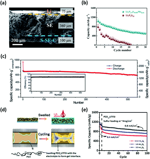 | ||
| Fig. 16 (a) Cross-sectional SEM image outlining the all-solid-state Li7P2.9S10.85Mo0.01 electrolyte with the integrated sulfur cathode and the Li metal anode. (b) Comparison of results for the cycling performance of Li–S cells using the conventional (Li7P3S11) and MoS2 doped (Li7P2.9S10.85Mo0.01) electrolytes. (c) Specific capacity vs. cycle number of the full-cell with the G-PPC-CPE based gel electrolyte with embedded SiO2 nanoparticles showing high cycle life with good coulombic efficiency. (d) Schematic illustrating the electrode with the PEO10LiTFSI polymer gel and the nanoscale confinement of polysulfides through the swelling mechanism. (e) The electrochemical performance of the Li–S cells employing the PEO10LiTFSI gel under different E/S ratios. (a and b) Reproduced with permission from ref. 161. Copyright 2017, Royal Society of Chemistry. (c) Reproduced with permission from ref. 162. Copyright 2018, Royal Society of Chemistry. (d and e) Reproduced with permission from ref. 163. Copyright 2017, American Chemical Society. | ||
Gel-based electrolytes also show promise in addressing the issues related to polysulfide dissolution. Huang et al. utilized a composite gel polymer electrolyte (G-PPC-CPE) embedded with SiO2 nanoparticles, which not only prevented the diffusion of polysulfides but also enhanced the ionic conductivity.162 The feasibility of this concept was demonstrated through a reversible capacity of 597.3 mA h g−1 after 500 cycles with a capacity retention of 85% at a current rate of 0.1 A g−1 (Fig. 16c). Chen et al. developed a swellable gel consisting of a soft PEO10LiTFSI polymer which acts as a nanoscale reservoir to confine polysulfides within the ion conducting interphase (Fig. 16d).163 Consequently, the full-cell exhibited an initial capacity of 1183 mA h g−1; moreover, the cell retained 87.3% of its initial capacity after 100 cycles under a lean E/S ratio of ∼3.3 μL mg−1 (Fig. 16e). This translates to the specific energy density of ∼250 W h kg−1 at the cell level. Therefore, a practical Li–S cell under lean electrolyte conditions is achieved through the strong binding ability of the swellable gel that simultaneously absorbs the electrolyte and forms an interphase-like network to immobilize polysulfides.
V. Nanoengineering separators
In recent years, research into separator modifications for Li–S batteries has gained rapid momentum. This is widely attributed to the commercial availability of polyolefin-based separators such as porous polyethylene (PE) and polypropylene (PP) membranes.164 Considering the intrinsic “shuttling” issues of Li–S batteries, modified separators are typically designed to regulate the migration of soluble polysulfides while allowing free-transfer of Li-ions. Indeed, there have been recent review articles on the modifications of commercial separators to control the polysulfide shuttling reaction.165,166 To prevent repetition, our focus here is to review the progress of nanoengineered separators that are specifically designed to address shuttling issues under high sulfur loading. Accordingly, this section will cover the modified separators that are either functionalized or engineered with nanomaterials for efficient and practical Li–S batteries. In addition, we will briefly mention how nanoengineering offers a potentially-scalable process for separator modifications to obtain thin and lightweight separators without adding unnecessary bulk materials or impedance to the overall cell system.Functionalizing separators with nanomaterials
Separators modified with a functional layer typically feature polysulfide-entrapping/rejecting materials to control the dissolution of polysulfides in an electrolyte. With respect to entrapping polysulfides, carbon-based nanomaterials have been considered promising due to their structure with abundant pores to physically trap the soluble polysulfides.167 For instance, Peng et al. proposed a mesoporous cellular graphene-modified “Janus” separator to intercept the polysulfide crossover.168 Such a modification ensured that the cell exhibits a high areal capacity of 5.5 mA h cm−2 with an areal loading of 5.3 mg cm−2. On the subject of rejecting polysulfides, Pei et al. configured a PP separator with 2D porous nitrogen-doped graphene nanosheets (G@PC/PP),169 which tunes the membrane with electronegativity to repel negatively charged polysulfide species. Thus, the resulting separator became lightweight and thin (0.07 mg cm−2 and 0.9 μm); also, the cell employing such a separator delivered stable 400 cycles at a specific capacity of 1183 mA h g−1 with a sulfur loading of 6 mg cm−2. Even with the higher loading of 12.1 mg cm−2, the cell managed an areal capacity of 16 mA h cm−2 for 100 cycles (Fig. 17a).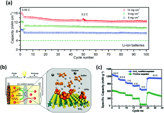 | ||
| Fig. 17 Employment of nanomaterials to functionalize separators. (a) Cycling performances of the Li–S batteries employing G@PC/PP separators with different areal sulfur loadings. (b) Schematic representing the role of a SnS2-modified separator within a Li–S battery. (c) Rate-capability test showcasing the improved sulfur utilization and polysulfide suppression for the Li–S cell with the SnS2-modified separator. (a) Reproduced with permission from ref. 169 Copyright 2018, Elsevier. (b and c) Reproduced with permission from ref. 170. Copyright 2019, Royal Society of Chemistry. | ||
Besides the carbon-based materials, inorganic materials have been investigated to effectively entrap and recycle polysulfides (Fig. 17b). Moorthy et al. incorporated tin-sulfide (SnS2) nanosheets to trap polysulfides and increase ion-conductivity.170 With the restricted polysulfide dissolution and decreased impedance, full-cells with the SnS2-modified separator demonstrated an improved specific capacity of 1300 mA h g−1; moreover, high rate capability was achieved with a capacity of 700 mA h g−1 at 5C (Fig. 17c). More recently, a polymer with intrinsic nano-porosity (PIN) was developed and grafted onto the micro-pores of a PP separator.171 Thus, the overall thickness of the separator remains unchanged while suppressing the shuttling behavior of polysulfides. Furthermore, full-cells with this PIN-functionalized separator operated with a sulfur loading of 4 mg cm−2 for up to 200 cycles with a discharge capacity of 780 mA h g−1.
Engineering composite separators with nanomaterials
Composite separators with unique structures work as a sieve which prevents diffusion of polysulfides and allows unrestricted flow of lithium ions. In other words, composite separators typically feature the merits of steric and electrostatic repulsion effects by combining carbon-based materials with other inorganic compounds such as nitrides, oxides and carbides.172 Tian et al. developed a graphene/MoN membrane (MoN-G/PP) where porous graphene provided a conducting network and a spatial accommodation for polysulfide entrapment; MoN, on the other hand, served as an additional barrier to chemically prevent polysulfides from shuttling.173 The full-cell with MoN-G/PP performed up to 500 cycles with the specific capacity maintained at 678 mA h g−1; additionally, a high areal capacity of 6.02 mA h cm−2 was achieved with the sulfur loading and the E/S ratio of 7 mg cm−2 and 6 μL mg−1, respectively (Fig. 18a).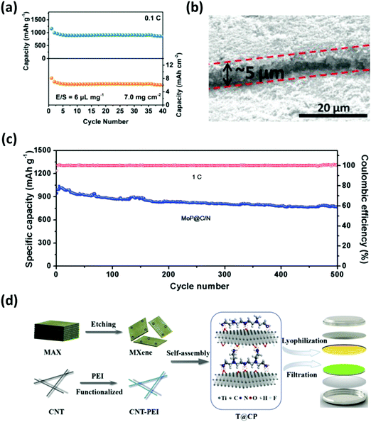 | ||
| Fig. 18 Modified separators with composite interlayers derived from nanomaterials. (a) Cycling stability test of the cell employing the MoN-G/PP separator with an areal sulfur loading of 7 mg cm−2. (b) Cross-view SEM image of MoP@C/N on a Celgard separator and (c) the cycling performance test with a sulfur content of 75 wt% at 1C. (d) Schematic diagram of the modified separator integrated with 2D MXene and CNT–PEI composite structures. (a) Reproduced with permission from ref. 173. Copyright 2019, Wiley-VCH. (b and c) Reproduced with permission from ref. 176. Copyright 2019, Wiley-VCH. (d) Reproduced with permission from ref. 179. Copyright 2019, Elsevier. | ||
Other graphene-based composite separators, such as 2D GO/0D LiF and 2D rGO/0D MoP,174,175 were also studied to restrict polysulfide shuttling with respectable sulfur loadings (∼3–4 mg cm−2). Niu's group configured a lightweight (0.8 mg cm−2) composite membrane by sandwiching a separator between N-doped carbon nanosheets and MoP hollow nanospheres (MoP@C/N).176 The MoP@C/N-coated separator (Fig. 18b) served as the polysulfide immobilizer through chemical and physical interactions; thus, the full-cell with ∼5 mg cm−2 of sulfur exhibited a discharge capacity of 765 mA h g−1 for up to 500 cycles (Fig. 18c). Carbon nanofibers (CNFs) and CNTs were also utilized as one of the components for composite separators. Lai et al. prepared a separator coated with hollow carbon nanofibers (HCNF)@δ-MnO2.177 Here, the structure of the HCNF afforded the physical confinement of polysulfides while the δ-MnO2 provided additional adsorption sites. Similarly, Jeong et al. designed a separator composed of a 1T exfoliated 2D MoS2@CNT-coated membrane to optimize polysulfide trapping and ion transfer.178
Guo et al. synergistically configured a separator with MXene (Ti3C2Tx) nanosheets and lithophilic CNT–polyethyleneimine (PEI) to effectively improve the redox kinetics of polysulfides and the ionic transport at the interface between a cathode and the separator (Fig. 18d).179 The Li–S cell in this case demonstrated an areal capacity of 7.1 mA h cm−2 with the sulfur loading and the E/S ratio of 5.8 mg cm−2 and 12 μL mg−1, respectively. The versatility of configuring the composite structure and its consistent performance under high sulfur loading prove that engineering a separator with nanomaterials is one of the most promising solutions for obtaining practical lightweight Li–S batteries.
VI. Summary and perspectives
In summary, a critical review of the recent research on various aspects of Li–S batteries has been presented. It is observed that most of the publications on Li–S batteries have considered only low sulfur loadings with an excessive amount of electrolyte that leads to low practical energy densities with almost no potential to outperform the current LIBs. From the practical standpoint, strategies to minimize the electrolyte/sulfur (E/S) ratio while maximizing the sulfur loading and its utilization are critically important. Under these conditions, the integration of and the interaction between components within a Li–S cell must be optimized and technologies must be advanced to overcome the limitations of Li–S batteries. To this end, the recent advances in nanoscience and nanoengineering can enable the development of efficient and practical cathodes, anodes, separators, and electrolytes. They can also resolve the intrinsic hurdles of Li–S batteries while delivering the electrochemical advantages under highly challenging conditions. The following perspectives on different aspects of science and engineering of Li–S batteries may be helpful to further research effort and bring major breakthroughs in the development of practical Li–S batteries:Perspectives on fundamentals
Although there have been in situ and ex situ investigations to catalog various sulfur species,180–182 the distribution and contribution of these species to reaction kinetics and the materials chemistry of the electrodes still remain unclear. Recently, the fundamental aspects of polysulfide transformation from HOLPs to LOLPs including their electronic states and physio-chemical nature have been reported. The idea is to develop a niche methodology that allows systematic transformation of larger quantities of sulfur to lithium polysulfides through the reaction with Li-ions from anode, and vice versa, without any loss in the capacity of the Li–S battery. Nevertheless, while pursuing this, the electrochemical polysulfide reaction involves a series of complex structural and phase evolutions, including the volume expansion in electrodes. An ideal approach to resolve the polysulfide shuttling is to introduce a mediator that can anchor polysulfides and accelerate the Li2S nucleation and decomposition efficiently without compromising the conductivity. However, this remains a challenge and the detailed mechanisms of this process are still not fully understood. Evidently, this calls for extensive theoretical and in operando studies using the tools of nano-characterization to trace precisely the dynamics of the conversion chemistry between various polysulfide species as well as the rearrangement of energy-storage molecules.Perspectives on technology
In addition to the scientific issues that are yet to be resolved, there are technological challenges that need to be addressed before the commercialization of Li–S batteries becomes a reality. To achieve a high energy density, the E/S ratio should be minimized while maximizing the sulfur loading and its utilization. For example, although the E/S ratio of 4 μL mg−1 can yield an energy density of 500 W h kg−1 or higher at the cell level,183 the rapid electrolyte consumption by the sulfur cathode during the repeated charging/discharging processes can result in a lower cycle life, especially for the cell with a lean amount of electrolyte. Therefore, a novel strategy to apply the conversion chemistry of polysulfides consistently and regulate the stable interphase of the cathode needs to be developed. It is also worth noting that the high-loaded cathode has to be engineered to withstand the volume change of sulfur to polysulfide conversions. We believe that a reliable high-sulfur loaded cathode without the use of an excessive amount of electrolyte and a stable anode without dendrite formation and corrosion with polysulfides will be the right approach to obtain a safe and practical Li–S battery. With respect to the industrial standards, most of the above-mentioned approaches are regrettably limited to the coin cells at the laboratory scale. Experimenting with pouch-cell configurations is one of the crucial steps to circumvent the limitations for practical applications.184–186 Therefore, further work should be done to verify the performance improvement in pouch cells.Perspectives on materials
Carbon-based nanomaterials have the history of efficiently improving the electrical conductivities of sulfur while blocking the migration of polysulfides and volume change. However, the addition of carbon material contributes to the inactive weight of the cathode; furthermore, the non-polar surface of carbon leads to the detachment of sulfur particles which compromises the energy densities. Recent efforts have led to polar and/or electrocatalytic materials for accelerating the reaction kinetics of polysulfide conversion to insoluble products.68,187 As summarized in this article, an efficient electrocatalyst should not only out-perform the polysulfide conversion but also prevent any unwanted side-reactions that compromise the stability of Li–S batteries. Such electrocatalysts can be actively used in battery cells and examined for higher sulfur loading to ensure practical applicability. The discharge capacities that are reported in many literature studies only consider the weight of the sulfur. However, the use of non-active components such as binders, conducting agents, catalysts and current collectors would contribute an additional weight to the entire cell configuration, which consequently reduces the actual energy density of Li–S batteries. Therefore, it is crucial to optimize each component within the cell that considers the total volume and mass while advancing the performance of Li–S batteries.Although the past decade has shown tremendous improvement in Li–S batteries, overcoming the above-mentioned challenges while setting an ideal design principle for commercially-viable Li–S batteries is still an ongoing research effort. New studies are therefore required that focus on basic sciences, new technology, and advanced materials development at the cell level that can bring the discharge capacity closer to its theoretical value. An additional strategy is also required for regulating the chemical equilibria between the active species at the nanoscale, while pursuing protection of the Li metal, low E/S ratio, high sulfur loading and maximum sulfur utilization.
Conflicts of interest
There are no conflicts to declare.Acknowledgements
This work was financially supported by the Asian Office of Aerospace R&D (FA2386-18-4075). W. C. acknowledges the seed funding from the Ark Power Tech. Co.References
- M. Armand and J.-M. Tarascon, Nature, 2008, 451, 652–657 CrossRef CAS PubMed.
- J. B. Goodenough, Energy Environ. Sci., 2014, 7, 14–18 RSC.
- P. G. Bruce, S. A. Freunberger, L. J. Hardwick and J.-M. Tarascon, Nat. Mater., 2012, 11, 19–29 CrossRef CAS.
- J. B. Goodenough and Y. Kim, Chem. Mater., 2010, 22, 587–603 CrossRef CAS.
- Z. W. Seh, Y. Sun, Q. Zhang and Y. Cui, Chem. Soc. Rev., 2016, 45, 5605–5634 RSC.
- R. Fang, G. Zhou, S. Pei, F. Li and H.-M. Cheng, Chem. Commun., 2015, 51, 3667–3670 RSC.
- S. Moon, Y. H. Jung, W. K. Jung, D. S. Jung, J. W. Choi and D. K. Kim, Adv. Mater., 2013, 25, 6547–6553 CrossRef CAS PubMed.
- S. Urbonaite, T. Poux and P. Novák, Adv. Energy Mater., 2015, 5, 1500118 CrossRef.
- M. Hagen, D. Hanselmann, K. Ahlbrecht, R. Maça, D. Gerber and J. Tübke, Adv. Energy Mater., 2015, 5, 1401986 CrossRef.
- D.-W. Wang, Q. Zeng, G. Zhou, L. Yin, F. Li, H.-M. Cheng, I. R. Gentle and G. Q. M. Lu, J. Mater. Chem. A, 2013, 1, 9382 RSC.
- S. S. Zhang, J. Power Sources, 2013, 231, 153–162 CrossRef CAS.
- R. Fang, S. Zhao, Z. Sun, D.-W. Wang, H.-M. Cheng and F. Li, Adv. Mater., 2017, 29, 1606823 CrossRef PubMed.
- J. W. Kim, J. D. Ocon, D.-W. Park and J. Lee, ChemSusChem, 2014, 7, 1265–1273 CrossRef CAS PubMed.
- Y. V. Mikhaylik and J. R. Akridge, J. Electrochem. Soc., 2004, 151, A1969 CrossRef CAS.
- J. Liang, Z.-H. Sun, F. Li and H.-M. Cheng, Energy Storage Mater., 2016, 2, 76–106 CrossRef.
- M. Yu, R. Li, M. Wu and G. Shi, Energy Storage Mater., 2015, 1, 51–73 CrossRef.
- J.-Q. Huang, Q. Zhang and F. Wei, Energy Storage Mater., 2015, 1, 127–145 CrossRef.
- Z. Liang, G. Zheng, C. Liu, N. Liu, W. Li, K. Yan, H. Yao, P.-C. Hsu, S. Chu and Y. Cui, Nano Lett., 2015, 15, 2910–2916 CrossRef CAS PubMed.
- C.-P. Yang, Y.-X. Yin, S.-F. Zhang, N.-W. Li and Y.-G. Guo, Nat. Commun., 2015, 6, 8058 CrossRef CAS PubMed.
- J.-S. Kim, D. W. Kim, H. T. Jung and J. W. Choi, Chem. Mater., 2015, 27, 2780–2787 CrossRef CAS.
- M. Broussely, P. Biensan and B. Simon, Electrochim. Acta, 1999, 45, 3–22 CrossRef CAS.
- G. Zheng, S. W. Lee, Z. Liang, H. W. Lee, K. Yan, H. Yao, H. Wang, W. Li, S. Chu and Y. Cui, Nat. Nanotechnol., 2014, 9, 618–623 CrossRef CAS PubMed.
- E. Kazyak, K. N. Wood and N. P. Dasgupta, Chem. Mater., 2015, 27, 6457–6462 CrossRef CAS.
- E. Peled, J. Electrochem. Soc., 1979, 126, 2047 CrossRef CAS.
- S. S. Zhang and J. A. Read, J. Power Sources, 2012, 200, 77–82 CrossRef CAS.
- S. Xiong, K. Xie, Y. Diao and X. Hong, J. Power Sources, 2013, 236, 181–187 CrossRef CAS.
- Y. Han, X. Duan, Y. Li, L. Huang, D. Zhu and Y. Chen, Mater. Res. Bull., 2015, 68, 160–165 CrossRef CAS.
- D. Eroglu, K. R. Zavadil and K. G. Gallagher, J. Electrochem. Soc., 2015, 162, A982–A990 CrossRef CAS.
- C. Jiang, E. Hosono and H. Zhou, Nano Today, 2006, 1, 28–33 CrossRef.
- J. Hassoun and B. Scrosati, Adv. Mater., 2010, 22, 5198–5201 CrossRef CAS PubMed.
- K. T. Lee and J. Cho, Nano Today, 2011, 6, 28–41 CrossRef CAS.
- M. Rana, S. A. Ahad, M. Li, B. Luo, L. Wang, I. Gentle and R. Knibbe, Energy Storage Mater., 2019, 18, 289–310 CrossRef.
- B. S. D.-H. Kim, M. S. B. Lee, K.-Y. Park and K. Kang, Chem. – Asian J., 2016, 11, 1288–1292 CrossRef CAS PubMed.
- Y. Son, J.-S. Lee, Y. Son, J.-H. Jang and J. Cho, Adv. Energy Mater., 2015, 5, 1500110 CrossRef.
- J.-G. Wang, K. Xie and B. Wei, Nano Energy, 2015, 15, 413–444 CrossRef CAS.
- W. G. Chong, J.-Q. Huang, Z.-L. Xu, X. Qin, X. Wang and J.-K. Kim, Adv. Funct. Mater., 2017, 27, 1604815 CrossRef.
- L. Borchardt, M. Oschatz and S. Kaskel, Chem. – Eur. J., 2016, 22, 7324–7351 CrossRef CAS PubMed.
- Z. Li, H. Bin Wu and X. W. (David) Lou, Energy Environ. Sci., 2016, 9, 3061–3070 RSC.
- D. Lv, J. Zheng, Q. Li, X. Xie, S. Ferrara, Z. Nie, L. B. Mehdi, N. D. Browning, J.-G. Zhang, G. L. Graff, J. Liu and J. Xiao, Adv. Energy Mater., 2015, 5, 1402290 CrossRef.
- M. S. Whittingham, Chem. Rev., 2014, 114, 11414–11443 CrossRef CAS PubMed.
- S. Moon, Y. H. Jung and D. K. Kim, J. Power Sources, 2015, 294, 386–392 CrossRef CAS.
- B. D. McCloskey, J. Phys. Chem. Lett., 2015, 6, 4581–4588 CrossRef CAS PubMed.
- S. Jin, S. Xin, L. Wang, Z. Du, L. Cao, J. Chen, X. Kong, M. Gong, J. Lu, Y. Zhu, H. Ji and R. S. Ruoff, Adv. Mater., 2016, 28, 9094–9102 CrossRef CAS PubMed.
- B. Liu, R. Fang, D. Xie, W. Zhang, H. Huang, Y. Xia, X. Wang, X. Xia and J. Tu, Energy Environ. Mater., 2018, 1, 196–208 CrossRef.
- S. Moon, J.-K. Yoo, Y. H. Jung, J.-H. Kim, Y. S. Jung and D. K. Kim, J. Electrochem. Soc., 2017, 164, A6417–A6421 CrossRef CAS.
- S. A. Ahad, P. R. Kumar, J.-H. Kim, D. J. Kim, P. Ragupathy and D. K. Kim, Electrochim. Acta, 2017, 246, 451–458 CrossRef.
- L. Qie and A. Manthiram, Adv. Mater., 2015, 27, 1694 CrossRef CAS PubMed.
- G. Zhou, L. Li, C. Ma, S. Wang, Y. Shi, N. Koratkar, W. Ren, F. Li and H.-M. Cheng, Nano Energy, 2015, 11, 356–365 CrossRef CAS.
- S.-H. Chung, C.-H. Chang and A. Manthiram, J. Power Sources, 2016, 334, 179–190 CrossRef CAS.
- H. M. Kim, H.-H. Sun, I. Belharouak, A. Manthiram and Y.-K. Sun, ACS Energy Lett., 2016, 1, 136–141 CrossRef CAS.
- R. Fang, S. Zhao, S. Pei, X. Qian, P.-X. Hou, H.-M. Cheng, C. Liu and F. Li, ACS Nano, 2016, 10, 8676–8682 CrossRef CAS PubMed.
- K. Sun, A. K. Matarasso, R. M. Epler, X. Tong, D. Su, A. C. Marschilok, K. J. Takeuchi, E. S. Takeuchi and H. Gan, J. Electrochem. Soc., 2018, 165, A416–A423 CrossRef CAS.
- N. B. Emerce and D. Eroglu, J. Electrochem. Soc., 2019, 166, A1490–A1500 CrossRef CAS.
- J. Xiao, G. Zhou, H. Chen, X. Feng, D. Legut, Y. Fan, T. Wang, Y. Cui and Q. Zhang, Nano Lett., 2019, 19, 7487–7493 CrossRef CAS PubMed.
- C. Deng, Z. Wang, S. Wang and J. Yu, J. Mater. Chem. A, 2019, 7, 12381–12413 RSC.
- Z. Ji, B. Han, Q. Li, C. Zhou, Q. Gao, K. Xia and J. Wu, J. Phys. Chem. C, 2015, 119, 20495–20502 CrossRef CAS.
- J. Park, J. Moon, C. Kim, J. H. Kang, E. Lim, J. Park, K. J. Lee, S.-H. Yu, J.-H. Seo, J. Lee, J. Heo, N. Tanaka, S.-P. Cho, J. Pyun, J. Cabana, B. H. Hong and Y.-E. Sung, NPG Asia Mater., 2016, 8, e272–e272 CrossRef CAS.
- Y.-S. Su, Y. Fu, T. Cochell and A. Manthiram, Nat. Commun., 2013, 4, 2985 CrossRef PubMed.
- H.-J. Peng and Q. Zhang, Angew. Chem., Int. Ed., 2015, 54, 11018–11020 CrossRef CAS PubMed.
- Y. Song, W. Cai, L. Kong, J. Cai, Q. Zhang and J. Sun, Adv. Energy Mater., 2019, 1, 1901075 CrossRef.
- S. A. Ahad, P. Ragupathy, S. Ryu, H. W. Lee and D. K. Kim, Chem. Commun., 2017, 53, 8782–8785 RSC.
- P. Ragupathy, S. A. Ahad, P. R. Kumar, H.-W. Lee and D. K. Kim, Adv. Sustainable Syst., 2017, 1, 1700083 CrossRef.
- S. A. Ahad, R. Pitchai, A. M. Beyene, S. H. Joo, D. K. Kim and H. W. Lee, ChemSusChem, 2018, 11, 3402–3409 CrossRef CAS PubMed.
- A. M. Beyene, J. H. Yun, S. A. Ahad, B. Moorthy and D. K. Kim, Appl. Surf. Sci., 2019, 495, 143544 CrossRef CAS.
- Z. Yi, F. Su, L. Huo, G. Cui, C. Zhang, P. Han, N. Dong and C. Chen, Appl. Surf. Sci., 2020, 503, 144446 CrossRef CAS.
- L. Ji, M. Rao, H. Zheng, L. Zhang, Y. Li, W. Duan, J. Guo, E. J. Cairns and Y. Zhang, J. Am. Chem. Soc., 2011, 133, 18522–18525 CrossRef CAS PubMed.
- S. Bhoyate, K. Mensah-Darkwa, P. K. Kahol and R. K. Gupta, Curr. Graphene Sci., 2017, 1, 26 Search PubMed.
- X. Liang, C. Hart, Q. Pang, A. Garsuch, T. Weiss and L. F. Nazar, Nat. Commun., 2015, 6, 5682 CrossRef PubMed.
- H.-J. Peng, T.-Z. Hou, Q. Zhang, J.-Q. Huang, X.-B. Cheng, M.-Q. Guo, Z. Yuan, L.-Y. He and F. Wei, Adv. Mater. Interfaces, 2014, 1, 1400227 CrossRef.
- G. S. Yi, E. S. Sim and Y.-C. Chung, Phys. Chem. Chem. Phys., 2017, 19, 28189–28194 RSC.
- Z. W. Seh, Q. Zhang, W. Li, G. Zheng, H. Yao and Y. Cui, Chem. Sci., 2013, 4, 3673 RSC.
- W. Li, Q. Zhang, G. Zheng, Z. W. Seh, H. Yao and Y. Cui, Nano Lett., 2013, 13, 5534–5540 CrossRef CAS.
- J. Xu, W. Zhang, H. Fan, F. Cheng, D. Su and G. Wang, Nano Energy, 2018, 51, 73–82 CrossRef CAS.
- Q. Pang, X. Liang, C. Y. Kwok and L. F. Nazar, J. Electrochem. Soc., 2015, 162, A2567–A2576 CrossRef CAS.
- E. Wiberg, N. Wiberg, A. F. Arnold and F. Holleman, Inorganic chemistry, Academic Press, 2001 Search PubMed.
- X. Liang, C. Y. Kwok, F. Lodi-Marzano, Q. Pang, M. Cuisinier, H. Huang, C. J. Hart, D. Houtarde, K. Kaup, H. Sommer, T. Brezesinski, J. Janek and L. F. Nazar, Adv. Energy Mater., 2016, 6, 1501636 CrossRef.
- X. Tao, J. Wang, C. Liu, H. Wang, H. Yao, G. Zheng, Z. W. Seh, Q. Cai, W. Li, G. Zhou, C. Zu and Y. Cui, Nat. Commun., 2016, 7, 11203 CrossRef CAS PubMed.
- J. Zhou, X. Liu, L. Zhu, J. Zhou, Y. Guan, L. Chen, S. Niu, J. Cai, D. Sun, Y. Zhu, J. Du, G. Wang and Y. Qian, Joule, 2018, 2, 2681–2693 CrossRef CAS.
- X. Chen, H.-J. Peng, R. Zhang, T.-Z. Hou, J.-Q. Huang, B. Li and Q. Zhang, ACS Energy Lett., 2017, 2, 795–801 CrossRef CAS.
- J. He, G. Hartmann, M. Lee, G. S. Hwang, Y. Chen and A. Manthiram, Energy Environ. Sci., 2019, 12, 344–350 RSC.
- S. Wang, H. Chen, J. Liao, Q. Sun, F. Zhao, J. Luo, X. Lin, X. Niu, M. Wu, R. Li and X. Sun, ACS Energy Lett., 2019, 4, 755–762 CrossRef CAS.
- O. Ogoke, S. Hwang, B. Hultman, M. Chen, S. Karakalos, Y. He, A. Ramsey, D. Su, P. Alexandridis and G. Wu, J. Mater. Chem. A, 2019, 7, 13389–13399 RSC.
- T. Zhou, W. Lv, J. Li, G. Zhou, Y. Zhao, S. Fan, B. Liu, B. Li, F. Kang and Q.-H. Yang, Energy Environ. Sci., 2017, 10, 1694–1703 RSC.
- Y. Zhong, K. R. Yang, W. Liu, P. He, V. Batista and H. Wang, J. Phys. Chem. C, 2017, 121, 14222–14227 CrossRef CAS.
- Y. Song, W. Zhao, L. Kong, L. Zhang, X. Zhu, Y. Shao, F. Ding, Q. Zhang, J. Sun and Z. Liu, Energy Environ. Sci., 2018, 11, 2620–2630 RSC.
- Q. Zhang, Y. Wang, Z. W. Seh, Z. Fu, R. Zhang and Y. Cui, Nano Lett., 2015, 15, 3780–3786 CrossRef CAS PubMed.
- Y. Yan, T. Lei, Y. Jiao, C. Wu and J. Xiong, Electrochim. Acta, 2018, 264, 20–25 CrossRef CAS.
- X. Tao, J. Wang, Z. Ying, Q. Cai, G. Zheng, Y. Gan, H. Huang, Y. Xia, C. Liang, W. Zhang and Y. Cui, Nano Lett., 2014, 14, 5288–5294 CrossRef CAS PubMed.
- Z. Li, Q. He, X. Xu, Y. Zhao, X. Liu, C. Zhou, D. Ai, L. Xia and L. Mai, Adv. Mater., 2018, 30, 1804089 CrossRef PubMed.
- L. Zhang, X. Chen, F. Wan, Z. Niu, Y. Wang, Q. Zhang and J. Chen, ACS Nano, 2018, 12, 9578–9586 CrossRef CAS PubMed.
- Z. Chen, W. Lv, F. Kang and J. Li, J. Phys. Chem. C, 2019, 123, 25025–25030 CrossRef CAS.
- F. Zhou, Z. Li, X. Luo, T. Wu, B. Jiang, L.-L. Lu, H.-B. Yao, M. Antonietti and S.-H. Yu, Nano Lett., 2018, 18, 1035–1043 CrossRef CAS PubMed.
- Z. Wang, J. Liu, L. Sun, Y. Zhang, Q. Fu, H. Xie and H. Sun, Chem. – Eur. J., 2018, 24, 14154–14161 CrossRef CAS PubMed.
- G. Zhou, H. Tian, Y. Jin, X. Tao, B. Liu, R. Zhang, Z. W. Seh, D. Zhuo, Y. Liu, J. Sun, J. Zhao, C. Zu, D. S. Wu, Q. Zhang and Y. Cui, Proc. Natl. Acad. Sci. U. S. A., 2017, 114, 840–845 CrossRef CAS PubMed.
- D. Guo, Z. Zhang, B. Xi, Z. Yu, Z. Zhou and X. Chen, J. Mater. Chem. A, 2020, 8, 3834–3844 RSC.
- T. Lei, W. Chen, J. Huang, C. Yan, H. Sun, C. Wang, W. Zhang, Y. Li and J. Xiong, Adv. Energy Mater., 2017, 7, 1601843 CrossRef.
- H. Wang, Q. Zhang, H. Yao, Z. Liang, H.-W. Lee, P.-C. Hsu, G. Zheng and Y. Cui, Nano Lett., 2014, 14, 7138–7144 CrossRef CAS.
- G. Ai, Q. Hu, L. Zhang, K. Dai, J. Wang, Z. Xu, Y. Huang, B. Zhang, D. Li, T. Zhang, G. Liu and W. Mao, ACS Appl. Mater. Interfaces, 2019, 11, 33987–33999 CrossRef CAS PubMed.
- H.-E. Wang, X. Li, N. Qin, X. Zhao, H. Cheng, G. Cao and W. Zhang, J. Mater. Chem. A, 2019, 7, 12068 RSC.
- Y.-X. Yin, S. Xin, Y.-G. Guo and L.-J. Wan, Angew. Chem., Int. Ed., 2013, 52, 13186–13200 CrossRef CAS PubMed.
- H. Park, H. S. Koh and D. J. Siegel, J. Phys. Chem. C, 2015, 119, 4675–4683 CrossRef CAS.
- A. Manthiram, Y. Fu and Y.-S. Su, Acc. Chem. Res., 2013, 46, 1125–1134 CrossRef CAS.
- S. Wang, X. Hou, Z. Zhong, K. Shen, G. Zhang, L. Yao and F. Chen, Sci. Rep., 2018, 8, 16133 CrossRef.
- P. Barai, A. Mistry and P. P. Mukherjee, Extrem. Mech. Lett., 2016, 9, 359–370 CrossRef.
- R. Fang, S. Zhao, P. Hou, M. Cheng, S. Wang, H.-M. Cheng, C. Liu and F. Li, Adv. Mater., 2016, 28, 3374–3382 CrossRef CAS.
- M. D. Patel, E. Cha, C. Kang, B. Gwalani and W. Choi, Carbon, 2017, 118, 120–126 CrossRef CAS.
- S. Lu, Y. Chen, X. Wu, Z. Wang and Y. Li, Sci. Rep., 2015, 4, 4629 CrossRef PubMed.
- M. Li, R. Carter, A. Douglas, L. Oakes and C. L. Pint, ACS Nano, 2017, 11, 4877–4884 CrossRef CAS PubMed.
- F. Zeng, A. Wang, W. Wang, Z. Jin and Y.-S. Yang, J. Mater. Chem. A, 2017, 5, 12879–12888 RSC.
- M. Shaibani, M. S. Mirshekarloo, R. Singh, C. D. Easton, M. C. D. Cooray, N. Eshraghi, T. Abendroth, S. Dörfler, H. Althues, S. Kaskel, A. F. Hollenkamp, M. R. Hill and M. Majumder, Sci. Adv., 2020, 6, eaay2757 CrossRef.
- J. H. Yun, J. H. Kim, D. K. Kim and H. W. Lee, Nano Lett., 2018, 18, 475–481 CrossRef CAS.
- D. Guan, J. A. Jeevarajan and Y. Wang, Nanoscale, 2011, 3, 1465 RSC.
- A. Abdul Razzaq, X. Yuan, Y. Chen, J. Hu, Q. Mu, Y. Ma, X. Zhao, L. Miao, J. Ahn, Y. Peng and Z. Deng, J. Mater. Chem. A, 2020, 8, 1298–1306 RSC.
- F. Ma, J. Liang, T. Wang, X. Chen, Y. Fan, B. Hultman, H. Xie, J. Han, G. Wu and Q. Li, Nanoscale, 2018, 10, 5634 RSC.
- J. W. Choi and D. Aurbach, Nat. Rev. Mater., 2016, 1, 16013 CrossRef CAS.
- J. Song, T. Xu, M. L. Gordin, P. Zhu, D. Lv, Y.-B. Jiang, Y. Chen, Y. Duan and D. Wang, Adv. Funct. Mater., 2014, 24, 1243–1250 CrossRef CAS.
- A. C. Kozen, C.-F. Lin, A. J. Pearse, M. A. Schroeder, X. Han, L. Hu, S.-B. Lee, G. W. Rubloff and M. Noked, ACS Nano, 2015, 9, 5884–5892 CrossRef CAS PubMed.
- E. Cha, M. D. Patel, J. Park, J. Hwang, V. Prasad, K. Cho and W. Choi, Nat. Nanotechnol., 2018, 13, 337–344 CrossRef CAS PubMed.
- E. Cha, M. D. Patel, T. Y. Choi and W. Choi, ECS Trans., 2018, 85, 295–302 CrossRef CAS.
- C. Yang, K. Fu, Y. Zhang, E. Hitz and L. Hu, Adv. Mater., 2017, 29, 1701169 CrossRef PubMed.
- D. Lin, Y. Liu and Y. Cui, Nat. Nanotechnol., 2017, 12, 194–206 CrossRef CAS PubMed.
- A. Zhamu, G. Chen, C. Liu, D. Neff, Q. Fang, Z. Yu, W. Xiong, Y. Wang, X. Wang and B. Z. Jang, Energy Environ. Sci., 2012, 5, 5701–5707 RSC.
- B. Moorthy, J. H. Kim, H. W. Lee and D. K. Kim, Energy Storage Mater., 2019, 24, 602–609 CrossRef.
- W. Cai, J. Zhou, G. Li, K. Zhang, X. Liu, C. Wang, H. Zhou, Y. Zhu and Y. Qian, ACS Appl. Mater. Interfaces, 2016, 8, 27679–27687 CrossRef CAS.
- J. Hassoun, J. Kim, D.-J. Lee, H.-G. Jung, S.-M. Lee, Y.-K. Sun and B. Scrosati, J. Power Sources, 2012, 202, 308–313 CrossRef CAS.
- B. Li, S. Li, J. Xu and S. Yang, Energy Environ. Sci., 2016, 9, 2025–2030 RSC.
- A. Bhargav, M. Wu and Y. Fu, J. Electrochem. Soc., 2016, 163, A1543–A1549 CrossRef CAS.
- P. Shi, T. Li, R. Zhang, X. Shen, X.-B. Cheng, R. Xu, J.-Q. Huang, X.-R. Chen, H. Liu and Q. Zhang, Adv. Mater., 2019, 31, 1807131 CrossRef PubMed.
- S.-K. Lee, S.-M. Oh, E. Park, B. Scrosati, J. Hassoun, M.-S. Park, Y.-J. Kim, H. Kim, I. Belharouak and Y.-K. Sun, Nano Lett., 2015, 15, 2863–2868 CrossRef CAS PubMed.
- M. Weinberger and M. Wohlfahrt-Mehrens, Electrochim. Acta, 2016, 191, 124–132 CrossRef CAS.
- N. Deng, W. Kang, Y. Liu, J. Ju, D. Wu, L. Li, B. S. Hassan and B. Cheng, J. Power Sources, 2016, 331, 132–155 CrossRef CAS.
- Y. Xiang, J. Li, J. Lei, D. Liu, Z. Xie, D. Qu, K. Li, T. Deng and H. Tang, ChemSusChem, 2016, 9, 3023–3039 CrossRef CAS PubMed.
- Z.-L. Xu, J.-K. Kim and K. Kang, Nano Today, 2018, 19, 84–107 CrossRef CAS.
- B. Li, H. Xu, Y. Ma and S. Yang, Nanoscale Horiz., 2019, 4, 77–98 RSC.
- C. Huang, J. Xiao, Y. Shao, J. Zheng, W. D. Bennett, D. Lu, L. V. Saraf, M. Engelhard, L. Ji, J. Zhang, X. Li, G. L. Graff and J. Liu, Nat. Commun., 2014, 5, 3015 CrossRef PubMed.
- L. Wang, Z. Yang, H. Nie, C. Gu, W. Hua, X. Xu, X. Chen, Y. Chen and S. Huang, J. Mater. Chem. A, 2016, 4, 15343–15352 RSC.
- X. Wang, Z. Wang and L. Chen, J. Power Sources, 2013, 242, 65–69 CrossRef CAS.
- H. M. Kim, J.-Y. Hwang, A. Manthiram and Y.-K. Sun, ACS Appl. Mater. Interfaces, 2016, 8, 983–987 CrossRef CAS PubMed.
- Y.-S. Su and A. Manthiram, Chem. Commun., 2012, 48, 8817 RSC.
- Z. Wang, J. Zhang, Y. Yang, X. Yue, X. Hao, W. Sun, D. Rooney and K. Sun, J. Power Sources, 2016, 329, 305–313 CrossRef CAS.
- X. Han, Y. Xu, X. Chen, Y.-C. Chen, N. Weadock, J. Wan, H. Zhu, Y. Liu, H. Li, G. Rubloff, C. Wang and L. Hu, Nano Energy, 2013, 2, 1197–1206 CrossRef CAS.
- J.-Q. Huang, B. Zhang, Z.-L. Xu, S. Abouali, M. Akbari Garakani, J. Huang and J.-K. Kim, J. Power Sources, 2015, 285, 43–50 CrossRef CAS.
- Z. Xiao, Z. Yang, L. Wang, H. Nie, M. Zhong, Q. Lai, X. Xu, L. Zhang and S. Huang, Adv. Mater., 2015, 27, 2891–2898 CrossRef CAS PubMed.
- K. Xie, K. Yuan, K. Zhang, C. Shen, W. Lv, X. Liu, J.-G. Wang and B. Wei, ACS Appl. Mater. Interfaces, 2017, 9, 4605–4613 CrossRef CAS PubMed.
- R. V. Salvatierra, G. A. López-Silva, A. S. Jalilov, J. Yoon, G. Wu, A. Tsai and J. M. Tour, Adv. Mater., 2018, 30, 1803869 CrossRef PubMed.
- M. Cuisinier, C. Hart, M. Balasubramanian, A. Garsuch and L. F. Nazar, Adv. Energy Mater., 2015, 5, 1401801 CrossRef.
- W. Chen, T. Lei, C. Wu, M. Deng, C. Gong, K. Hu, Y. Ma, L. Dai, W. Lv, W. He, X. Liu, J. Xiong and C. Yan, Adv. Energy Mater., 2018, 8, 1702348 CrossRef.
- J. Gao, M. A. Lowe, Y. Kiya and H. D. Abruña, J. Phys. Chem. C, 2011, 115, 25132–25137 CrossRef CAS.
- H. Pan, X. Wei, W. A. Henderson, Y. Shao, J. Chen, P. Bhattacharya, J. Xiao and J. Liu, Adv. Energy Mater., 2015, 5, 1500113 CrossRef.
- M. Cuisinier, P.-E. Cabelguen, B. D. Adams, A. Garsuch, M. Balasubramanian and L. F. Nazar, Energy Environ. Sci., 2014, 7, 2697–2705 RSC.
- Y. He, Z. Chang, S. Wu and H. Zhou, J. Mater. Chem. A, 2018, 6, 6155–6182 RSC.
- H.-L. Wu, M. Shin, Y.-M. Liu, K. A. See and A. A. Gewirth, Nano Energy, 2017, 32, 50–58 CrossRef CAS.
- C. Hu, H. Chen, Y. Shen, D. Lu, Y. Zhao, A.-H. Lu, X. Wu, W. Lu and L. Chen, Nat. Commun., 2017, 8, 479 CrossRef PubMed.
- W. Yang, W. Yang, A. Song, L. Gao, G. Sun and G. Shao, J. Power Sources, 2017, 348, 175–182 CrossRef CAS.
- Q. Pang, A. Shyamsunder, B. Narayanan, C. Y. Kwok, L. A. Curtiss and L. F. Nazar, Nat. Energy, 2018, 3, 783–791 CrossRef CAS.
- R. C. Xu, X. H. Xia, Z. J. Yao, X. L. Wang, C. D. Gu and J. P. Tu, Electrochim. Acta, 2016, 219, 235–240 CrossRef CAS.
- Z. Lin and C. Liang, J. Mater. Chem. A, 2015, 3, 936–958 RSC.
- Y. Seino, T. Ota, K. Takada, A. Hayashi and M. Tatsumisago, Energy Environ. Sci., 2014, 7, 627–631 RSC.
- Y. Kato, S. Hori, T. Saito, K. Suzuki, M. Hirayama, A. Mitsui, M. Yonemura, H. Iba and R. Kanno, Nat. Energy, 2016, 1, 16030 CrossRef CAS.
- H. Nagata and Y. Chikusa, J. Power Sources, 2014, 264, 206–210 CrossRef CAS.
- R. Xu, X. Xia, X. Wang, Y. Xia and J. Tu, J. Mater. Chem. A, 2017, 5, 2829–2834 RSC.
- H. Huang, F. Ding, H. Zhong, H. Li, W. Zhang, X. Liu and Q. Xu, J. Mater. Chem. A, 2018, 6, 9539–9549 RSC.
- J. Chen, W. A. Henderson, H. Pan, B. R. Perdue, R. Cao, J. Z. Hu, C. Wan, K. S. Han, K. T. Mueller, J.-G. Zhang, Y. Shao and J. Liu, Nano Lett., 2017, 17, 3061–3067 CrossRef CAS PubMed.
- L. Ye, X. Shi, Z. Zhang, J. Liu, X. Jian, M. Waqas and W. He, Adv. Mater. Interfaces, 2017, 4, 1601236 CrossRef.
- D. Chen, K. Wen, W. Lv, Z. Wei and W. He, Phys. Status Solidi RRL, 2018, 12, 1800249 CrossRef.
- M. Rana, M. Li, X. Huang, B. Luo, I. Gentle and R. Knibbe, J. Mater. Chem. A, 2019, 7, 6596–6615 RSC.
- T.-Z. Hou, X. Chen, H.-J. Peng, J.-Q. Huang, B.-Q. Li, Q. Zhang and B. Li, Small, 2016, 12, 3283–3291 CrossRef CAS PubMed.
- H.-J. Peng, D.-W. Wang, J.-Q. Huang, X.-B. Cheng, Z. Yuan, F. Wei and Q. Zhang, Adv. Sci., 2016, 3, 1500268 CrossRef PubMed.
- F. Pei, L. Lin, A. Fu, S. Mo, D. Ou, X. Fang and N. Zheng, Joule, 2018, 2, 323–336 CrossRef CAS.
- B. Moorthy, S. Kwon, J.-H. Kim, P. Ragupathy, H. M. Lee and D. K. Kim, Nanoscale Horiz., 2019, 4, 214–222 RSC.
- X. Yu, H. Wu, J. H. Koo and A. Manthiram, Adv. Energy Mater., 2020, 10, 1902872 CrossRef.
- Y. C. Jeong, J. H. Kim, S. Nam, C. R. Park and S. J. Yang, Adv. Funct. Mater., 2018, 28, 1707411 CrossRef.
- D. Tian, X. Song, M. Wang, X. Wu, Y. Qiu, B. Guan, X. Xu, L. Fan, N. Zhang and K. Sun, Adv. Energy Mater., 2019, 9, 1901940 CrossRef CAS.
- X. Ni, T. Qian, X. Liu, N. Xu, J. Liu and C. Yan, Adv. Funct. Mater., 2018, 28, 1706513 CrossRef.
- M. Li, C. Wang, L. Miao, J. Xiang, T. Wang, K. Yuan, J. Chen and Y. Huang, J. Mater. Chem. A, 2018, 6, 5862–5869 RSC.
- Z. Sun, X. Wu, Z. Peng, J. Wang, S. Gan, Y. Zhang, D. Han and L. Niu, Small, 2019, 15, 1902491 CrossRef PubMed.
- Y. Lai, P. Wang, F. Qin, M. Xu, J. Li, K. Zhang and Z. Zhang, Energy Storage Mater., 2017, 9, 179–187 CrossRef.
- Y. C. Jeong, J. H. Kim, S. H. Kwon, J. Y. Oh, J. Park, Y. Jung, S. G. Lee, S. J. Yang and C. R. Park, J. Mater. Chem. A, 2017, 5, 23909–23918 RSC.
- D. Guo, F. Ming, H. Su, Y. Wu, W. Wahyudi, M. Li, M. N. Hedhili, G. Sheng, L. J. Li, H. N. Alshareef, Y. Li and Z. Lai, Nano Energy, 2019, 61, 478–485 CrossRef CAS.
- G. Zhang, Z.-W. Zhang, H.-J. Peng, J.-Q. Huang and Q. Zhang, Small Methods, 2017, 1, 1700134 CrossRef.
- R. Xu, J. Lu and K. Amine, Adv. Energy Mater., 2015, 5, 1500408 CrossRef.
- M. Wild, L. O’Neill, T. Zhang, R. Purkayastha, G. Minton, M. Marinescu and G. J. Offer, Energy Environ. Sci., 2015, 8, 3477–3494 RSC.
- L. Qie, C. Zu and A. Manthiram, Adv. Energy Mater., 2016, 6, 1502459 CrossRef.
- P.-Y. Zhai, H.-J. Peng, X.-B. Cheng, L. Zhu, J.-Q. Huang, W. Zhu and Q. Zhang, Energy Storage Mater., 2017, 7, 56–63 CrossRef.
- Q. Pang, X. Liang, C. Y. Kwok, J. Kulisch and L. F. Nazar, Adv. Energy Mater., 2017, 7, 1601630 CrossRef.
- X. B. Cheng, C. Yan, J. Q. Huang, P. Li, L. Zhu, L. Zhao, Y. Zhang, W. Zhu, S. T. Yang and Q. Zhang, Energy Storage Mater., 2017, 6, 18–25 CrossRef.
- Z. Yuan, H.-J. Peng, T.-Z. Hou, J.-Q. Huang, C.-M. Chen, D.-W. Wang, X.-B. Cheng, F. Wei and Q. Zhang, Nano Lett., 2016, 16, 519–527 CrossRef CAS PubMed.
| This journal is © The Royal Society of Chemistry 2020 |

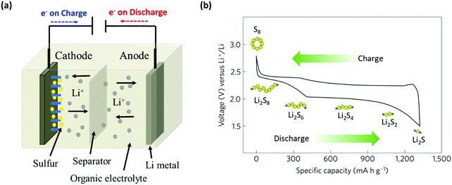


![[triple bond, length as m-dash]](https://www.rsc.org/images/entities/char_e002.gif) N
N


