
 Open Access Article
 This Open Access Article is licensed under a Creative Commons Attribution-Non Commercial 3.0 Unported Licence
Tailoring hierarchical zeolite composites with two distinct frameworks for fine-tuning the product distribution in benzene alkylation with ethanol†
Thidarat
Imyen
 a,
Wannaruedee
Wannapakdee
a,
Somlak
Ittisanronnachai
b,
Thongthai
Witoon
c and
Chularat
Wattanakit
*a
a,
Wannaruedee
Wannapakdee
a,
Somlak
Ittisanronnachai
b,
Thongthai
Witoon
c and
Chularat
Wattanakit
*a
aDepartment of Chemical and Biomolecular Engineering, School of Energy Science and Engineering, Nanocatalysts and Nanomaterials for Sustainable Energy and Environment Research Network of NANOTEC, Vidyasirimedhi Institute of Science and Technology, Rayong 21210, Thailand. E-mail: chularat.w@vistec.ac.th
bFrontier Research Center (FRC), Vidyasirimedhi Institute of Science and Technology, Rayong 21210, Thailand
cCenter of Excellence on Petrochemical and Materials Technology, Department of Chemical Engineering, Faculty of Engineering, Kasetsart University, Bangkok 10900, Thailand
First published on 19th May 2020
Abstract
A hierarchical zeolite composite, MOR@ZSM-5, with two distinct frameworks has been successfully fabricated via the repeated crystallization of ZSM-5 nanocrystals on mordenite surfaces. To avoid their phase separation, the surface of mordenite was pretreated with tetra(n-butyl)ammonium hydroxide (TBAOH) to induce the formation of the ZSM-5 nuclei, and it was subsequently modified by the continuous growth of nanocrystalline ZSM-5 on the entire area of the mordenite surfaces. Interestingly, the fully overgrown MOR@ZSM-5 composite exhibits a remarkable improvement in the ethylbenzene selectivity (>60%) obtained from the alkylation of benzene with ethanol with respect to isolated zeolites and their physical mixture due to the enhanced external surface area and hierarchical porosity as well as the reasonable acidity provided by the fully dispersed ZSM-5 nanocrystals on the mordenite surfaces. Moreover, coke species deposited on the designed composites are likely located at the external surfaces and do not considerably deteriorate the catalytic performance, whereas they are deposited predominantly in the micropores over the incompletely overgrown MOR@ZSM-5 composite. The present study illustrates the advantages of the overgrown zeolite composites of two incompatible frameworks in tailoring the hierarchical porosity, adjusting the acidic properties, and eventually controlling the product selectivity in acid-catalyzed reactions such as the alkylation of benzene with ethanol.
Introduction
Zeolites are crystalline aluminosilicate materials with a well-defined microporous structure and they exhibit various outstanding properties ranging from high surface areas and high acidity to ion-exchange ability and shape selectivity.1–4 Over the past decades, they have been employed as acid catalysts in several potential applications in the petrochemical industry, for example, catalytic cracking, hydrocracking, oligomerization, isomerization, and alkylation.5–8 Unfortunately, the applications of zeolites are often hampered by the restricted diffusion of the reactants and/or products in their microporous system (<2 nm).9 These pore diffusion limitations result in low active site accessibility, low catalytic performance, and rapid catalyst deactivation.10–12 Therefore, to overcome these drawbacks, many attempts have been made to design zeolites possessing a shorter diffusion path length with at least two levels of porosity, namely hierarchical zeolites.11–15To date, various hierarchical zeolites have been successfully prepared by several approaches such as post-treatment, recrystallization, templating method, and bond blocking.11–14,16–22 Typically, the post-treatment approach mainly involves the desilication and dealumination of zeolites via alkaline leaching and acid leaching as well as steaming, respectively.11,20,23 However, the disadvantage of post-treatment is that some parts of the zeolite framework are destroyed, eventually leading to partial amorphization.24 Meanwhile, the soft/hard templating method has been revealed as one of the most effective methods to control the hierarchical porous structure of zeolites.12,25–27 Recently, there have been several reports on the development of hierarchical zeolite nanosheets, nanowires, and nanocrystals, which exhibit a significant improvement in the catalytic performance for various reactions with respect to the conventional ones.13,18,19,28–32 These observations are related to the fact that the inter-particle porosity can provide a higher accessibility of active sites and also accommodate large molecules existing during the reaction, thus making them more applicable for catalytic processes involving bulky molecules.13,18,19 In addition, hierarchical zeolites exhibit considerable changes in the product selectivity due to the suppression of further reactions, corresponding to enhanced diffusion to and/or from the reaction sites in the micropores through the mesopores.13
Although the internal and external surfaces (channels and crystal faces) of zeolites are considerably different in terms of the OH group concentration, acid strength, and shape selectivity, the contribution of the catalytic sites on the external surface of zeolites to the overall reaction should not be neglected.33,34 Indeed, an excessively high external surface acidity facilitates side reactions without pore restriction, leading to a decrease in the desired product selectivity.35 To circumvent this problem, the modification of their external surface acidity is one of the most promising strategies to reduce their acidic density, which is obtained by one of the following three main approaches: (i) elemental surface modification; (ii) chemical vapor deposition (CVD); (iii) chemical liquid deposition (CLD).34,36–38 Apart from the above-mentioned methods, the fabrication of core–shell zeolite composites is a fascinating aspect for improving the surface properties, and thus, for manipulating the catalytic properties of zeolites. The growth of a continuous shell over zeolite core crystals may not only modify the morphology of the zeolite but also the textural properties, the acidity, and the shape selectivity, all of which can control the product distribution in various reactions.21,34,35,39
Several core–shell zeolite composites, such as mordenite@ZSM-5,34 ZSM-5@silicalite-1,35,40–42 mordenite@silicate-1,33 SAPO-34@ZSM-5,43,44 ZSM-5@SAPO-34,45 ZSM-5@SAPO-5,46 ZSM-5@SAPO-11,47 ZSM-5@ZSM-22,48 beta@silicalite-1,49 and Y@beta50 have been reported in the literature. Most of them have highlighted the crucial importance of compatibility between the core and shell materials in the successful formation of core–shell structured composites.34,51 Typically, the compatibility of two zeolite components can be illustrated in terms of their structural types, framework compositions, crystallization conditions, stability of the core crystals, as well as the rapidity of shell growth.45,49,51 However, the endeavors for synthesizing core–shell composite by direct growth of different zeolite structures on a certain core component have not been successful.33 To circumvent the chemical or structural incompatibility between the core crystals and the shell precursors, various strategies have been employed, for example, the pre-adsorption of nanoseeds on the core surface and a subsequent hydrothermal reaction to induce a well intergrown shell,33,34,49 the use of core crystals as the nutrients for shell growth,24,45,50 and the pretreatment of core crystals with a template required for the zeolite shell growth.34,44 It was reported that mordenite surfaces dissolved and reorganized into ZSM-5 nanoclusters during core pretreatment with the template, which can act as crystallization centers in the formation of the polycrystalline ZSM-5 shell.34 Various zeolite composites with a core–shell structure have revealed enhanced catalytic performance, especially in terms of product selectivity for many reactions, such as fluid catalytic cracking,46 hydrocracking,24 dehydrogenation,43 alkylation,48,52,53 ethanol dehydration,44 and methanol to olefins or aromatics owing to their altered textural properties, modified surface acidities, and tuned diffusion and shape selective behaviors.41,54,55
Ethylbenzene (EB) is a crucial feedstock for the production of styrene, which is one of the most important industrial monomers for plastics and textiles.56,57 Currently, ethylbenzene is mainly produced by the alkylation of benzene with ethylene or ethanol over acidic zeolite-based catalysts.5,58,59 The use of ethanol instead of ethylene suppresses coke formation, leading to a longer catalyst lifetime, and also benefits in terms of the economic significance due to a lower cost of biomass derived ethanol.57,60 However, there are several side products obtained from the alkylation process including toluene, xylene, and higher aromatics (C9+) formed by secondary reactions on the acidic sites. Therefore, the modification of the acidic properties of the catalyst surface is of crucial importance in tuning the product selectivity in benzene alkylation.
Among various zeolites, ZSM-5 as well as mordenite have been widely employed in many petrochemical processes, particularly in alkylation.61 However, a conventional zeolite often suffers from lower catalytic performance and rapid catalyst deactivation due to the excessively high acidity and large crystal size. In general, the location and strength of the acidic sites are considered as crucial factors affecting the catalytic behavior. In addition, the crystal size of a zeolite also has a great impact on the catalytic activity and selectivity. For example, with a crystal size in the nanoscale, a larger inter-crystalline void space is provided, resulting in higher pore volume, and more accessible acidic sites, all of which lead to higher activity, lower coke content, and improved stability.17,57,62 Therefore, to modify a zeolite combined with small crystals and a reasonable acidity, the fabrication of the core–shell structure of the mordenite core with nanocrystalline ZSM-5 would be advantageous. To the best of our knowledge, although the potential applications of modified catalysts in alkylation have been demonstrated, the catalytic performance of core–shell mordenite@ZSM-5 composite has not been evaluated in benzene alkylation.
Motivated by the benefits offered by zeolite composites with core–shell structures, which allow the tuning of physicochemical properties so as to enhance the catalytic activity, tune the product distribution, and reduce coke formation in benzene alkylation with ethanol, a novel zeolite composite of mordenite with low Si/Al ratio (∼9) as the core with hierarchical nanocrystalline ZSM-5 with higher silica ZSM-5 (Si/Al ratio ∼ 70) as the shell has been successfully fabricated. Because of the difficulty in growing high silica ZSM-5 onto incompatible mordenite crystal surfaces, in this study, the overgrowth of continuous nanocrystalline ZSM-5 shells was successfully achieved via the pretreatment of mordenite with tetra(n-butyl)ammonium hydroxide (TBAOH), followed by repeated crystallization of nanocrystalline ZSM-5. The degree of nanocrystalline ZSM-5 surface coverage is related to the number of repeated cycles of ZSM-5 crystallization on the mordenite surfaces. To illustrate the benefits of the designed materials containing different types of zeolites, the effects of the morphology, textural properties, and the acidic properties of the composites in fine-tuning the product selectivity obtained from benzene alkylation with ethanol were also demonstrated. This first example presents an efficient synthetic approach that allows the complete overgrowth of commercial mordenite with nanocrystalline ZSM-5 and also opens up interesting aspects for the application of core–shell zeolite composites in tuning the product distribution in the alkylation of benzene with ethanol.
Experimental
Materials
Conventional mordenite (HSZ-600: H-form, Si/Al of 9) was supplied by Tosoh, Japan. Tetraethyl orthosilicate (TEOS: ≥99.0%, Sigma-Aldrich), aluminium isopropoxide (Al[OCH(CH3)2]3: ≥98.0%, Sigma-Aldrich), tetra(n-butyl)ammonium hydroxide (TBAOH: 40%, Leonid Chemicals), and sodium hydroxide (NaOH: 98%, Carlo Erba) were used as the starting materials for the synthesis of nanocrystalline ZSM-5. Benzene (99.9%, QRec), ethanol (99.9%, QRec), and nitrogen gas (N2: 99.999%, Praxair) were used for testing the catalytic activity without any further purification.Fabrication of mordenite@nanocrystalline ZSM-5 composites
Commercial mordenite was firstly pretreated with TBAOH by following the method in the previous report34 with some modifications. In a typical procedure, 2 g of commercial mordenite was mixed with 5 mL of 5% TBAOH and stirred at room temperature for 1 h before the hydrothermal treatment at 130 °C for 24 h. Subsequently, the pretreated mordenite was filtered and washed with deionized water, and dried overnight at 100 °C.To prepare the mordenite@nanocrystalline ZSM-5 composites, there are two methods including the single-step synthesis (SS) and the repeated or continuous overgrowth (CS) of ZSM-5 on the mordenite surfaces. To obtain the one-step crystallized zeolite composite, 1.08 g of pretreated mordenite was added into the nanocrystalline ZSM-5 gel precursor containing 8.67 g of TEOS, 8.10 g of TBAOH, 0.08 g of aluminium isopropoxide, 0.02 g of NaOH, and 2.3 g of deionized water. After stirring at room temperature for 36 h, the mixture was transferred to a Teflon-lined stainless steel autoclave for crystallization at 130 °C for 84 h. Then, the solid product was obtained by filtering and washing with deionized water, drying overnight at 100 °C, and calcination in air at 550 °C for 6 h. The synthesized product is denoted as MOR@ZSM-5(SS).
In order to obtain continuous nanocrystalline ZSM-5 overgrown on the entire mordenite surfaces, the ZSM-5 crystallization step was repeated thrice. Firstly, 2.16 g of the pretreated mordenite was added into the nanocrystalline ZSM-5 gel precursor containing 8.67 g of TEOS, 8.10 g of TBAOH, 0.08 g of aluminium isopropoxide, 0.02 g of NaOH, and 2.3 g of deionized water. After stirring at room temperature for 36 h, the mixture was transferred to a Teflon lined stainless steel autoclave for crystallization at 130 °C for 12 h. After that, the solid product was obtained by filtering and washing with deionized water, followed by drying at 100 °C overnight. Subsequently, 1.08 g of the product obtained from the first crystallization was further mixed with the nanocrystalline ZSM-5 gel precursor having a similar composition as that in the first crystallization step and the mixture was stirred at room temperature for 36 h. After crystallization at 130 °C for 84 h, the solid product was filtered and washed with deionized water, dried at 100 °C overnight, and calcined in air at 550 °C for 6 h. Then, 1.08 g of MOR@ZSM-5 was again added into the nanocrystalline ZSM-5 gel precursor. After stirring at room temperature for 36 h, the mixture was transferred to a Teflon-lined stainless steel autoclave for the third crystallization at 130 °C for 84 h. Finally, the solid product was obtained by filtering and washing with deionized water, drying at 100 °C overnight, and calcination in air at 550 °C for 6 h. The synthesized product is denoted as MOR@ZSM-5(CS).
Furthermore, the pure hierarchical ZSM-5 nanosheets were also synthesized by following the method in the previous report.18 Typically, the gel precursor containing 8.67 g of TEOS, 8.10 g of TBAOH, 0.08 g of aluminium isopropoxide, 0.02 g of NaOH, and 2.3 g of deionized water was prepared. The resultant mixture was stirred at room temperature for 12 h and was then subjected to hydrothermal treatment at 130 °C for 24 h. The obtained product was collected by filtering and washing with deionized water, drying at 100 °C overnight, and calcination in air at 550 °C for 6 h. The corresponding Si/Al ratio of the synthesized product is 67.4 and it is denoted as ZSM-5-NS.
All the synthesized samples were converted to the H+ form by ion-exchange with 1 M NH4NO3 solution at 80 °C for 2 h and the process was repeated thrice. Finally, the solid products were calcined in air at 550 °C for 4 h.
Characterization
The X-ray diffraction (XRD) patterns were recorded in the 2θ range of 5° to 50° with a step size of 1° min−1 on a Bruker D8 ADVANCE diffractometer with Cu Kα radiation operated at 40 kV and 40 mA. The Si/Al ratio of the composite products was determined by X-ray fluorescence (XRF) analysis performed on a Bruker model S8 TIGER sequential WDXRF. Fourier transform infrared (FTIR) spectra were collected at room temperature in the range from 4000 to 400 cm−1 with 16 scans using an FTIR spectrometer (PerkinElmer). Depth profile analysis using X-ray photoelectron spectroscopy (XPS) was performed on a JEOL JPS-9010 equipped with non-monochromatic Mg Kα X-rays (1253.6 eV). To record the elemental depth profiles, the sample was etched by an argon ion gun at the etching rate of 0.5 nm s−1 and the spectra were obtained at approximately 30 nm depth intervals. The atomic composition was estimated using the relatively integrated peak areas of the Si 2p3/2 and Al 2p3/2 orbitals. Scanning electron microscopy (SEM) and transmission electron spectroscopy (TEM) were performed on a JEOL JSM-7610F with an accelerating voltage of 1 kV and a JEOL JEM ARM200F with an accelerating voltage of 200 kV, respectively. To conduct the elemental analysis, both the microscopes were equipped with the Energy Dispersive Spectrometer (EDS) (Oxford X-max 150 mm2 for SEM and JEOL JED-2300T 100 mm2 for TEM). N2 adsorption–desorption isotherms were measured at −196 °C on a MicrotracBEL, BELSORP-max model. Prior to the measurement, the sample was degassed at 300 °C for 24 h. By using the N2 sorption data, the specific surface area (SBET) was determined by the Brunauer–Emmett–Teller equation and the total pore volume (Vtotal) was obtained from the data at P/P0 of 0.99. Meanwhile, the micropore surface area (Smicro), the external surface area (Sext), and the micropore volume (Vmicro) were estimated by the t-plot method. Solid state 27Al NMR spectroscopy was performed on a Bruker AVANCE III HD (400 MHz) digital NMR spectrometer operated at the magnetic field strength of 9.4 T. The spectra were recorded at the frequency of 104.3 MHz with 2500 scans, a relaxation delay of 3 s, and a single-pulse of 5 μs.Temperature-programmed desorption of ammonia (NH3-TPD) and O2-temperature-programmed oxidation (O2-TPO) were carried out using a BELCAT II instrument equipped with a thermal conductivity detector (TCD). For the NH3-TPD experiment, after pretreatment under the He flow at 500 °C for 1 h, the sample was saturated with NH3 at 100 °C for 30 min. Then, NH3 desorption was conducted in the temperature range of 100 to 800 °C with a ramping rate of 10 °C min−1. For the O2-TPO experiment, after pretreatment under the He flow at 300 °C for 2 h, O2-TPO was performed in the temperature range of 100 to 900 °C with a heating rate of 5 °C min−1 under 5% O2/He flow of 50 mL min−1. The Raman spectra were collected on a Senterra Dispersive Raman spectrometer (Bruker) using laser excitation with a wavelength of 532 nm in the spectral range of 270–1730 cm−1. The measurement was repeated thrice at six different positions with the integration time of 30 s.
Catalytic performance testing via the alkylation of benzene with ethanol
In the typical procedure, benzene alkylation with ethanol was carried out in a fixed-bed continuous flow reactor (3/8-inch diameter) packed with 0.2 g of the catalyst (50/80 mesh). Prior to the catalytic activity testing, the catalyst was pretreated with N2 flow at 550 °C for 3 h. Subsequently, the reactant feed containing benzene and ethanol in the volumetric ratio of 2![[thin space (1/6-em)]](https://www.rsc.org/images/entities/char_2009.gif) :1 was introduced into the reactor at 450 °C with a flow rate of 1.5 g h−1 by using an HPLC pump (FLUSYS, PLM 707-1) and 30 mL min−1 of N2 was used as the carrier gas. The ratio of the catalyst weight to the reactant flow rate (W/FBenzene+EtOH) was 0.133 gcat·h mol−1, corresponding to the weight hourly space velocity of 0.5 h−1. The outlet stream was analyzed by an online gas chromatograph (Agilent Technologies GC-7890B) equipped with an FID detector and a PORABON-Q column (10 m × 0.25 mm, 3 μm with 2 particle trap) at an interval time of 1 h. For the reaction study, the catalytic performances in terms of reactant conversion and product selectivity were evaluated from the peak area of the obtained GC chromatograph based on the carbon atom basis percentage and the molar percentage. The atomic balance of all the experiments was calculated based on the carbon numbers and it was found to be in the range of 85.5 ± 4.0%. Consequently, ethanol conversion (XEtOH), benzene conversion (XBenzene), and product selectivity (Si) were calculated by using eqn (1)–(3), respectively:
:1 was introduced into the reactor at 450 °C with a flow rate of 1.5 g h−1 by using an HPLC pump (FLUSYS, PLM 707-1) and 30 mL min−1 of N2 was used as the carrier gas. The ratio of the catalyst weight to the reactant flow rate (W/FBenzene+EtOH) was 0.133 gcat·h mol−1, corresponding to the weight hourly space velocity of 0.5 h−1. The outlet stream was analyzed by an online gas chromatograph (Agilent Technologies GC-7890B) equipped with an FID detector and a PORABON-Q column (10 m × 0.25 mm, 3 μm with 2 particle trap) at an interval time of 1 h. For the reaction study, the catalytic performances in terms of reactant conversion and product selectivity were evaluated from the peak area of the obtained GC chromatograph based on the carbon atom basis percentage and the molar percentage. The atomic balance of all the experiments was calculated based on the carbon numbers and it was found to be in the range of 85.5 ± 4.0%. Consequently, ethanol conversion (XEtOH), benzene conversion (XBenzene), and product selectivity (Si) were calculated by using eqn (1)–(3), respectively: | (1) |
 | (2) |
 | (3) |
Results and discussion
Catalyst characterization
After the pristine mordenite was hydrothermally treated with TBAOH for 24 h, the XRD pattern of the pretreated mordenite did not change significantly with respect to the pristine mordenite (Fig. S1†), suggesting that the mordenite framework can be preserved in alkaline TBAOH solution. However, the pretreated mordenite exhibits a lower crystallinity (75.2%) in comparison to the pristine mordenite (87.9%) (Table S1†), suggesting that some parts of mordenite likely decomposed to aluminosilicate species during the pretreatment process. Indeed, TBAOH is an efficient structure directing-agent (SDA) for the formation of ZSM-5 nanocrystals, and therefore, some parts of aluminosilicate species that dissolved from mordenite during the hydrothermal pretreatment could be reorganized into small ZSM-5 nanoclusters with the aid of TBAOH.34 Subsequently, these small nanoclusters can serve as the seeds, thus inducing the further growth of nanocrystalline ZSM-5 on mordenite surfaces during ZSM-5 crystallization via the single-step synthesis (SS) and continuous overgrowth (CS) approaches.As depicted in Fig. 1A, the XRD patterns of the synthesized zeolite composites exhibit characteristic diffraction peaks belonging to both MOR and MFI frameworks, confirming the co-existence of mordenite and ZSM-5 phases in the synthesized composites. For instance, the peaks at 2θ of 6.5°, 9.8°, 13.5°, 15.3°, 19.7°, 22.4°, 25.7°, 26.4°, and 27.7° are attributed to the MOR framework,63,64 while the peaks at 2θ of 7.9°, 8.7°, 23.1°, and 23.9° correspond to the MFI framework.45,65 However, the intensity of the diffraction peaks related to the mordenite phase is significantly decreased in the case of MOR@ZSM-5(CS) with respect to MOR@ZSM-5(SS), suggesting that the fraction of mordenite to ZSM-5 in the composite is reduced in the case of MOR@ZSM-5(CS). It is, therefore, reasonable to assume that the fully covered ZSM-5 layers are more dominant in MOR@ZSM-5(CS) due to repeated ZSM-5 crystallization. Moreover, according to the IR spectra (Fig. 1B), both the composite samples show an IR peak at 545 cm−1 belonging to double five-membered rings of pentasil units, which is a characteristic of the MFI framework.66,67
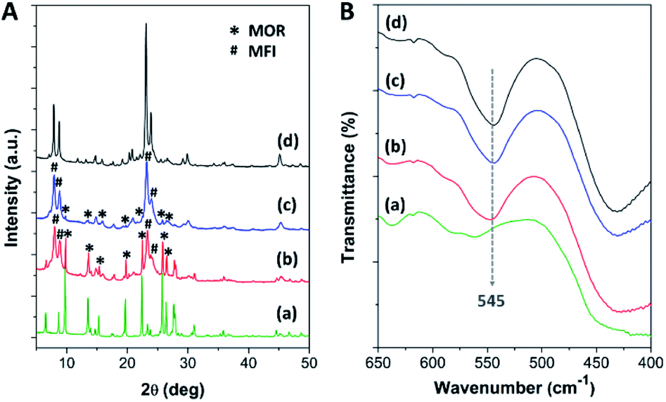 | ||
| Fig. 1 (A) The XRD patterns and (B) the FTIR spectra of (a) mordenite, (b) MOR@ZSM-5(SS), (c) MOR@ZSM-5(CS), and (d) ZSM-5-NS. | ||
The different morphology of the synthesized MOR@ZSM-5 composites is revealed by scanning electron micrographs (SEM) with respect to the isolated mordenite and hierarchical ZSM-5 (Fig. 2(a, b) and S2†). Pristine commercial mordenite is in the form of aggregated non-homogeneous ellipsoidal crystals with the size in the micron range (Fig. S2(a)†). Evidently, a morphology similar to that of pretreated mordenite is still observed with respect to the pristine one (Fig. S2(b)†). Consistent with the XRD results, the small ZSM-5 nanoclusters cannot be observed on the pretreated mordenite likely due to the disordered orientation and limited quantity.34 Meanwhile, the pure hierarchical ZSM-5 presents spherical assemblies of ZSM-5 nanosheets with the particle size in the range of 150–200 nm (Fig. S2(c)†) and it is similar to that described in the previous report.18
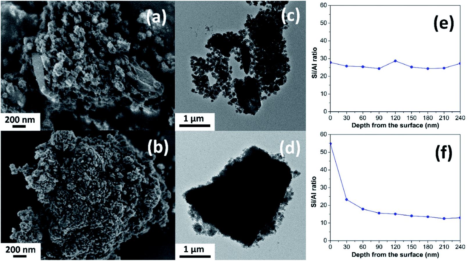 | ||
| Fig. 2 SEM images (a and b), TEM images (c and d), and the Si/Al ratio as a function of depth from the surface obtained from the XPS depth profile analyses (e and f) of (a, c and e) MOR@ZSM-5(SS) and (b, d and f) MOR@ZSM-5(CS). | ||
In addition, the morphology of both MOR@ZSM-5(SS) and MOR@ZSM-5(CS) composites is obviously different due to the different number of ZSM-5 crystallization cycles. For instance, in the case of MOR@ZSM-5(SS), which is obtained by the single-step crystallization of ZSM-5 on mordenite surfaces, the full coverage of mordenite by nanocrystalline ZSM-5 cannot be accomplished (Fig. 2a), demonstrating that some parts of mordenite are exposed together with the isolated ZSM-5 nanoparticles. On the other hand, in the case of MOR@ZSM-5(CS) prepared by repeated ZSM-5 crystallization, mordenite crystals are entirely covered by ZSM-5 nanocrystals and the complete overgrowth of nanocrystalline ZSM-5 on mordenite surfaces is eventually achieved (Fig. 2b). These observations can be explained by the fact that ZSM-5 partly overgrown on mordenite obtained from the first crystallization step can act as seeds or nuclei, which can induce the growth of the ZSM-5 layer in further crystallization steps, thus eventually leading to the formation of a continuous nanocrystalline ZSM-5 shell on the mordenite core.33,34 Noticeably, the ZSM-5 phase at the external surface of MOR@ZSM-5(CS) composites is mainly present as very highly dispersed nanocrystals on mordenite surfaces.
To further confirm the structure of the zeolite composites, transmission electron microscopy (TEM) was employed. As shown in Fig. 2(c and d), the external surface of the zeolite composites is rather rough compared to pristine mordenite (Fig. S3(a)†), indicating that the mordenite crystals are covered by nanocrystalline ZSM-5 layers. Although there are many spherical nanoparticles of ZSM-5 observed on the mordenite surface for MOR@ZSM-5(SS), some parts of mordenite are still exposed at the outermost surfaces of the composite. On the other hand, the full coverage of nanocrystalline ZSM-5 on mordenite was achieved only in the case of the MOR@ZSM-5(CS) sample. In addition, the interface between two zeolite components as well as the stacking of nanosized ZSM-5 crystals in MOR@ZSM-5(CS) are observed in the TEM images with higher magnification (100 kX) (Fig. S4†). Based on the representative TEM images (Fig. S4†), the ZSM-5 phase of MOR@ZSM-5(SS) and MOR@ZSM-5(CS) is composed of nanoparticles with the size of ca. 6.5 and 11.5 nm, respectively. However, it is difficult to clearly observe the core–shell structure of the MOR@ZSM-5(CS) sample by using the TEM image. Therefore, other characterization techniques are required to further prove the core–shell structure of the composite.
Indeed, the Si/Al ratios of the isolated mordenite and ZSM-5 nanosheets are significantly different (Table 1). Fortunately, XPS depth profile analysis can be used to obtain the information regarding the coverage of ZSM-5 on the mordenite crystals by monitoring the Si/Al ratio of the zeolite composites as a function of etching time, which is related to the depth from the surface (Fig. 2(e and f)). In case of the MOR@ZSM-5(CS) samples, the highest Si/Al ratio can be observed at the outermost surface (e.g., 0 nm) with the value close to that of isolated ZSM-5 and it decreases with increasing depth from the surface and eventually becomes constant at the value close to that of bare mordenite, demonstrating that the nanocrystalline ZSM-5 phase is dominant at the outermost surface, while the mordenite phase is dominant at the inner core (Fig. 2f). In strong contrast to this, for the MOR@ZSM-5(SS) sample, the Si/Al ratio is constant along the depth from the surface with the value close to the average Si/Al ratio estimated from the XRF technique (Fig. 2e and Table 1), indicating the non-homogeneous growth of ZSM-5 on the mordenite surface and confirming that the complete overgrowth of nanocrystalline ZSM-5 on the mordenite crystals cannot be achieved for this sample.
| Sample | Si/Al ratioa | S BET (m2 g−1) | S micro (m2 g−1) | S ext (m2 g−1) | V total (cm3 g−1) | V micro (cm3 g−1) | V ext (cm3 g−1) | V ext/Vtotal | HFh |
|---|---|---|---|---|---|---|---|---|---|
| a Si/Al ratio determined by the XRF technique. b BET specific surface area. c Microporous surface area. d External surface area. e Total pore volume. f Micropore volume. g V ext = Vtotal − Vmicro. h Hierarchy factor defined as (Vmicro/Vtotal) × (Sext/SBET). | |||||||||
| Mordenite | 9 | 521 | 500 | 21 | 0.27 | 0.19 | 0.08 | 0.30 | 0.028 |
| MOR@ZSM-5(SS) | 24 | 569 | 335 | 234 | 0.91 | 0.15 | 0.76 | 0.84 | 0.068 |
| MOR@ZSM-5(CS) | 42 | 645 | 488 | 157 | 0.73 | 0.22 | 0.51 | 0.70 | 0.073 |
| ZSM-5-NS18 | 67 | 542 | 296 | 246 | 0.86 | 0.12 | 0.74 | 0.86 | 0.063 |
In addition, to further confirm the homogeneity of the nanocrystalline ZSM-5 layers, SEM-EDS elemental analysis was also performed. As expected, the surface composition in terms of the Si/Al ratio of the MOR@ZSM-5(SS) sample is varied across the surface with a value of 10 to 40 and it relates to that region in which mordenite is dominant and exhibits lower Si/Al ratio, while the region in which nanocrystalline ZSM-5 is dominant presents higher Si/Al ratio (Fig. S5(a)†). In strong contrast to this, the Si/Al ratio of MOR@ZSM-5(CS) is uniform over the entire surface of the particles (Fig. S5(b)†), indicating the homogeneous distribution of ZSM-5 crystals over the external surface of mordenite.
The formation pathways of MOR@ZSM-5(SS) and MOR@ZSM-5(CS) illustrated in Scheme 1 are proposed based on SEM and TEM images. During the composite fabrication, there are two possible nucleation centers competing with each other for the growth of ZSM-5 crystals in the system: one is in the synthesis gel and the other is on the external surface of the mordenite crystals (Scheme 1A).45 For the first crystallization cycle, ZSM-5 is preferably grown at the nucleation centers in the synthesis gel instead of on the mordenite surfaces due to the incompatible framework structures and compositions of mordenite and ZSM-5 (Scheme 1B), thus resulting in partially covered mordenite by ZSM-5 together with the presence of the separated ZSM-5 phase (Scheme 1C), as evidenced by the SEM and TEM images of MOR@ZSM-5(SS). Interestingly, with a further increase in the number of crystallization steps, ZSM-5 growth on mordenite crystals became more dominant as ZSM-5 partly overgrown on mordenite obtained from the first crystallization can act as the seeds, which can induce the further growth of ZSM-5, thus eventually leading to a continuous nanocrystalline ZSM-5 coating over the entire mordenite surfaces (Scheme 1D), as evidenced by the SEM and TEM images of MOR@ZSM-5(CS).
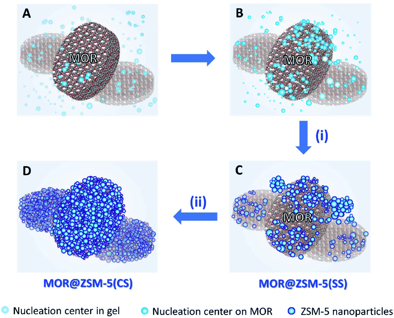 | ||
| Scheme 1 Illustration of the proposed formation pathways of MOR@ZSM-5(SS) and MOR@ZSM-5(CS) via (i) single-step crystallization (via A, B, and C); (ii) continuous crystallization of nanocrystalline ZSM-5 on the mordenite surfaces (D). | ||
To examine the textural properties of the zeolite composites, N2 adsorption/desorption isotherms of the zeolite composites, along with those of pure mordenite and hierarchical ZSM-5 nanosheet, are illustrated in Fig. 3A. Commercial mordenite typically displays a type I N2 isotherm with a steep N2 uptake at low relative pressure (P/P0 < 0.01), corresponding to the micropore filling in the microporous structure.68 Meanwhile, the ZSM-5 nanosheet and all the composite samples exhibit a combination of type I and type IV N2 isotherms with a hysteresis loop at high relative pressure (P/P0 > 0.90), which contributes to capillary condensation in open large pores due to inter-crystal porosity.39,69 Moreover, the BJH pore size distribution derived from the adsorption branch of the isotherm reveals a broad peak in the range between 30 and 80 nm for the zeolite composites and between 30 and 120 nm for ZSM-5-NS (Fig. 3B), indicating the presence of macro/mesopores created from the assemblies of nanosized ZSM-5 crystals and the interparticle voids.
 | ||
| Fig. 3 (A) N2 adsorption/desorption isotherms and (B) BJH pore size distribution of (a) mordenite, (b) MOR@ZSM-5(SS), and (c) MOR@ZSM-5(CS). | ||
The corresponding textural properties of all the samples were summarized in Table 1. Interestingly, the BET specific surface area (SBET), the external surface area (Sext), the total pore volume (Vtotal), as well as the macro/mesopore volume (Vext) of the composites were significantly enhanced in comparison to pristine mordenite due to a higher fraction of meso/macroporosity. Interestingly, a lower fraction of macro/mesopore volume (Vext/Vtotal) of MOR@ZSM-5(CS) with respect to MOR@ZSM-5(SS) and the ZSM-5 nanosheet can be directly related to its morphology, in which the ZSM-5 phase is present as nanocrystals and are densely stacked on mordenite surfaces (Fig. 2(b and d)).
However, one can anticipate that the use of external surface area (Sext) and macro/mesopore volume (Vext) values to evaluate the catalytic performance of the synthesized zeolite composites is not sufficient, as the interplay between the catalytic function due to the micropores and the accessible function provided by mesopores/macropores is important.70 Therefore, hierarchy factor (HF), defined as the product of the relative micropore volume (Vmicro/Vtotal) and the relative external surface area (Sext/SBET), is a powerful tool to investigate the hierarchical porosity.70 Interestingly, hierarchy factor is significantly enhanced in case of the MOR@ZSM-5(CS) sample (Table 1) with respect to the others, demonstrating that the external surface area is clearly improved due to highly dispersed ZSM-5 nanocrystals on the mordenite crystals, while the micropore volume is not severely penalized upon the fabrication of the zeolite composite. This makes it clear that the textural properties as well as the hierarchical porosity of the zeolite can be tailored by the overgrowth of nanocrystalline ZSM-5 on mordenite crystals.
The coordination of Al atoms in the zeolite samples was investigated by 27Al MAS NMR spectroscopy (Fig. S6(A)†). Typically, the peak at 55 ppm is assigned to tetrahedrally coordinated Al in the zeolite framework, while the peak at 0 ppm is assigned to octahedrally coordinated Al or extra-framework Al.71,72 Therefore, an intense band at 55 ppm with a very weak band at 0 ppm indicates that most of the aluminium can be incorporated into the zeolite framework.
To further investigate the acidic properties in terms of acidic density and acidic strength of the synthesized zeolite composites, the NH3-TPD profiles of all the zeolite samples present two main NH3 desorption features centered at about 180–200 °C and 400–550 °C, which are attributed to the desorption of NH3 from weak and strong acid sites, respectively, as shown in Fig. 4A. The corresponding desorption temperatures as well as the weak/strong acidic densities of each sample are summarized in Table 2.
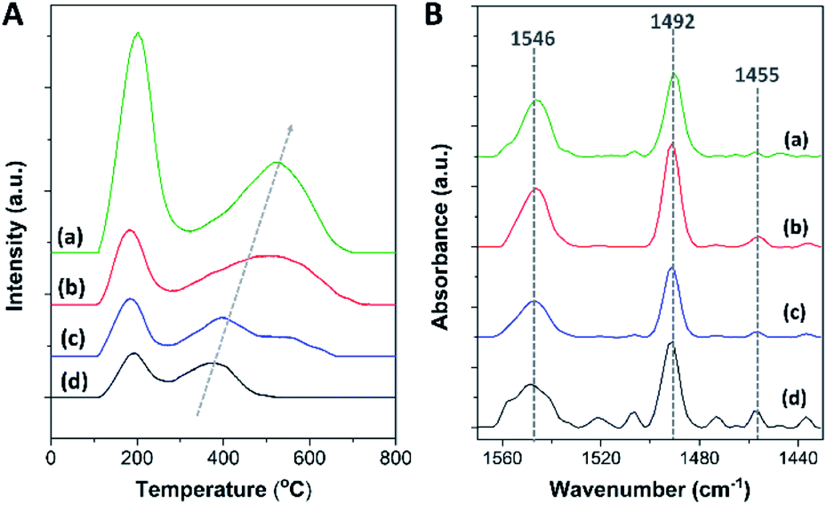 | ||
| Fig. 4 (A) NH3-TPD profiles and (B) FTIR spectra obtained after the desorption of pyridine at 150 °C of (a) mordenite, (b) MOR@ZSM-5(SS), (c) MOR@ZSM-5(CS), and (d) ZSM-5-NS. | ||
| Sample | Acid amounta (mmol g−1) | Amount of Brønsted acidityb (mmol g−1) | ||
|---|---|---|---|---|
| Weak (180–200 °C) | Strong (400–550 °C) | Total | ||
| a Determined by Gaussian deconvolution of the NH3-TPD profiles. b Estimated based on the NH3-TPD and Py-IR data. | ||||
| Mordenite | 0.48 | 0.53 | 1.01 | 0.98 |
| MOR@ZSM-5(SS) | 0.15 | 0.38 | 0.53 | 0.48 |
| MOR@ZSM-5(CS) | 0.12 | 0.22 | 0.34 | 0.31 |
| ZSM-5-NS | 0.07 | 0.11 | 0.18 | 0.16 |
According to the NH3-TPD data, it is demonstrated that bare mordenite exhibits the highest acidic density and acidic strength, while the pure ZSM-5 nanosheet presents the lowest acidic density and acidic strength, which is attributed to their different Si/Al ratios and zeolite topologies. Interestingly, the total acidity as well as the acidic strength of all the synthesized zeolite composites are in between those of the isolated mordenite and hierarchical ZSM-5 nanosheets, and also depend on the fraction of each zeolite component in the composite. For example, a lower acid amount as well as acidic strength of MOR@ZSM-5(CS) than that of MOR@ZSM-5(SS) is related to its higher fraction of lower acidity of the nanocrystalline ZSM-5 coating at the outermost surfaces of the composite. The above results suggest that the acidic properties of the zeolites are adjustable according to the different degree of surface coverage of nanocrystalline ZSM-5 on mordenite surfaces.
In general, the amount of strong Brønsted acid sites is related to the number of tetrahedral Al in the zeolite framework (i.e., chemical shift at 55 ppm in the 27Al MAS NMR spectra), as the acidic protons are required to compensate the negative charges caused by Al substitution for Si atoms in the zeolite framework.4,73 Therefore, in order to obtain more information about the different types of acidic sites, the FTIR analysis of pyridine adsorption (Py-IR) was also performed. Besides bridged hydroxyl groups in the zeolite framework, there are other types of acidic sites formed in the zeolite structure such as silanol groups and hydroxyl groups associated with extra-framework Al.74 Typically, these different types of acidic sites can be observed in the OH vibration region of the FTIR spectrum. As displayed in Fig. S6(B),† three negative bands are detected in the FTIR spectra for pyridine adsorption at about 3745 cm−1, 3660–3672 cm−1, and 3570–3600 cm−1, corresponding to the terminal silanol groups, hydroxyl groups linked to extra-framework Al and/or partially hydrolyzed framework Al, and acidic bridged hydroxyl groups in the zeolite framework, respectively.74–76 The negative feature of these bands is due to the consumption of OH groups on pyridine adsorption. It is noteworthy that only a trace amount of octahedral Al is detected in all the zeolite samples according to the 27Al NMR spectra (Fig. S6(A)†). Therefore, with a significant intensity of the IR peak at 3600–3672 cm−1 and a trace amount of octahedral Al, this band is likely attributed to the partially extra-framework Al anchored to the zeolitic framework with tetrahedral coordination. Interestingly, three hierarchical zeolite samples (MOR@ZSM-5(SS), MOR@ZSM-5(CS), and ZSM-5-NS) exhibit an intense IR band at 3745 cm−1, whereas mordenite presents this band with a significantly lower intensity. Hence, the above observations demonstrate that silanol groups are more relevant in these hierarchical zeolites in comparison to mordenite.
In addition, as shown in Fig. 4B, three IR bands are detected at about 1455, 1492, and 1546 cm−1, corresponding to pyridine adsorbed on different acidic sites. For instance, the IR peaks at 1455 and 1546 cm−1 are attributed to pyridine adsorbed on Lewis acidic sites (L) and Brønsted acidic sites (B), respectively.75 Meanwhile, the IR peak at 1492 cm−1 is assigned to pyridine coordinated to both Lewis and Brønsted acidic sites.75 The results demonstrate that a low amount of Lewis acidic sites is observed in all the samples, suggesting that most of the acidic sites in all the samples are Brønsted acidic sites, in accordance with the 27Al MAS NMR spectra. Accordingly, the amount of Brønsted acidic sites can be estimated using the NH3-TPD data together with Py-IR analysis (Table 2). A lower amount of Brønsted acidic sites in the composites with respect to bare mordenite is directly related to their higher Si/Al ratios, as a lower amount of framework Al can lead to a lower number of acidic protons for charge compensation due to the increased fraction of high silica ZSM-5.
Catalytic performance testing via the alkylation of benzene with ethanol
To illustrate the benefits of the synthesized zeolite composites with their tailored properties, the alkylation of benzene with ethanol was used as the model reaction. Generally, benzene alkylation with ethanol proceeds via electrophilic substitution on the aromatic ring through a carbenium ion-type mechanism over an acidic catalyst.61,77,78 Primarily, ethanol dehydration on Brønsted acidic sites is required for the formation of ethyl cation or ethylene, which can subsequently react with benzene to form ethylbenzene (EB) as the desired product.78 However, this reaction involves many complicated processes, for instance, alkylation of benzene with ethylene to ethylbenzene, isomerization and further alkylation of ethylbenzene, oligomerization of ethylene, followed by cracking, as well as the generation of other aromatics.59 To avoid the interference by further reactions, the ratio of benzene to ethanol is fixed at 2:1. It was reported that a lower volume fraction of benzene can induce the formation of diethylbenzene owing to the higher alkylation activity of ethylbenzene caused by the positive inductive effect of the ethyl group and eventually, the catalyst can be easily deactivated.79
Accordingly, the catalytic performance in benzene alkylation, in terms of reactant conversion and product selectivity of all the samples, was tested at 450 °C as a function of time on stream (TOS) for 24 h, as shown in Fig. 5 and S7.† To elucidate the effect of the full coverage of mordenite by nanocrystalline ZSM-5 on the catalytic performance, physically mixed mordenite and ZSM-5, denoted as MOR-ZSM-5(mix), with a Si/Al ratio comparable to that of MOR@ZSM-5(CS) was also investigated. The results demonstrate that ethanol conversion of about 90–100% was achieved for all the samples (Fig. 5A, S7(A) and Table S2†), suggesting that most of the ethanol was consumed under the present circumstance. However, the difference in benzene conversion over various catalysts is observed in the order MOR@ZSM-5(CS) > MOR@ZSM-5(SS) ∼ MOR-ZSM-5(mix) > ZSM-5-NS > mordenite. Indeed, a high ratio of ethanol to benzene conversion is related to the fact that a fraction of ethanol is converted by other reactions instead of alkylation78 and probably gives other by-products such as ethylene, oligomerization products, and coke species. Notably, in spite of its highest acidic density, mordenite shows the lowest benzene conversion, indicating low accessibility of the active sites and mass transfer restriction due to the microporous structure of conventional mordenite.10–12 As expected, benzene conversion is improved over all the zeolite composites with respect to pristine mordenite. This observation is related to the presence of mesopores created between the adjacent ZSM-5 nanosized crystals that can promote the accessibility of the active sites and mass transport in the zeolite. Compared to the pure ZSM-5 nanosheet, only the MOR@ZSM-5(CS) sample presents a significant improvement in the benzene conversion with the average value of 44.9%, whereas other zeolite composites give a significantly lower average value of ca. 34%. This observation indicates that the full coverage of nanocrystalline ZSM-5 on mordenite can play a crucial role in the enhancement of the catalytic activity towards benzene alkylation.
Interestingly, the product distribution observed over different catalysts is obviously different (Fig. 5B, S7(B) and Table S2†). Indeed, ethylbenzene is considered as the main product over all the samples except for pristine mordenite, which gives ethylene as the main product (e.g., average ethylene selectivity of 89.4%) with a very low ethylbenzene selectivity (ca. 6.2%). The low catalytic performance of pristine mordenite in benzene ethylation is likely related to its very high concentration of Brønsted acidic sites coinciding with a large crystal size. Although Brønsted acidic sites are the active sites for this reaction, it was reported that with a very high number of strong Brønsted acid sites and a large crystal size, the produced ethylbenzene would be strongly adsorbed on the zeolite and subsequently, is easy to crack into benzene or transform into coke species, resulting in lower benzene conversion as well as ethylbenzene selectivity.57 It was also reported that the high ethylene selectivity over mordenite was accounted for by its unique structural features, namely, the so-called “side pockets”, where likely only one molecule of ethanol can enter, thus favoring ethanol dehydration to ethylene.80 The above results demonstrate that the catalytic performance towards benzene alkylation is not only affected by acidity but also the crystal size as well as the textural properties.
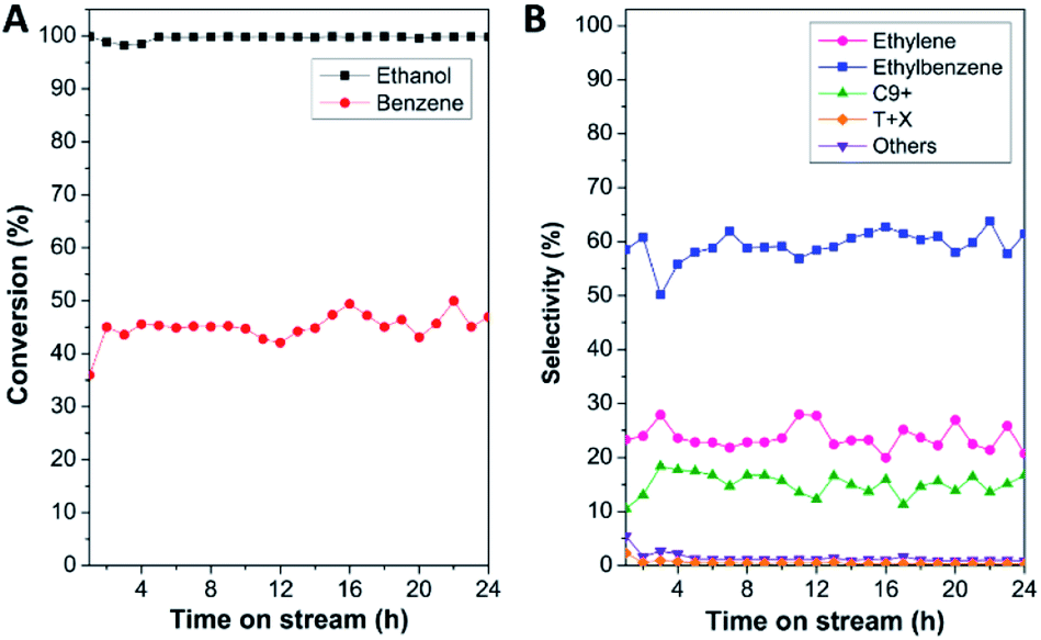 | ||
| Fig. 5 (A) Reaction conversion (%) and (B) product selectivity (%) over the MOR@ZSM-5(CS) sample in benzene alkylation at 450 °C as a function of time on stream (TOS) for 24 h. | ||
Contrary to mordenite, the pure ZSM-5 nanosheet presents a higher ethylbenzene selectivity (ca. 42.4%) with a comparable value of ethylene selectivity (ca. 49.7%), suggesting that a higher fraction of ethylene produced from ethanol dehydration can further react with benzene and eventually promote ethylbenzene formation. Moreover, in the case of zeolite composites, ethylbenzene becomes the main product, illustrating that the zeolite composites are more selective towards ethylbenzene formation with respect to bare mordenite and the ZSM-5 nanosheet. However, in the case of partially overgrown composite (MOR@ZSM-5(SS)), the ethylbenzene selectivity is not significantly improved with respect to ZSM-5-NS as well as in the case of the MOR-ZSM-5(mix) sample, whose mordenite and ZSM-5 are phase separated. In strong contrast to this, for the MOR@ZSM-5(CS) sample, the selectivity of ethylbenzene as well as heavy aromatics (C9+) is clearly enhanced, while the ethylene selectivity is significantly decreased with respect to other samples, demonstrating that alkylation can be considerably promoted via the complete coverage of nanocrystalline ZSM-5 on the mordenite crystals. This observation confirms that a reasonable acidity of MOR@ZSM-5(CS) for benzene alkylation can be achieved through the complete overgrowth of low acidity nanocrystalline ZSM-5 on the mordenite surfaces. Indeed, ethylbenzene can further react with ethylene via secondary reactions to generate further alkylated products such as heavy aromatics (C9+). As a result, the generation of heavy aromatics is at the expense of ethylbenzene.61 This makes it clear that the product distribution in the alkylation of benzene can be tuned with the view of controlling the physicochemical properties of the zeolite composites via the complete overgrowth of another zeolite.
As discussed above, the alkylation performance of the catalyst can be directly affected by both the acidic properties and the hierarchical porosity of the catalysts. Therefore, the relationship between the ethylbenzene yield and the catalyst properties (the Brønsted acid amount and the hierarchy factor) of different catalysts is illustrated in Fig. 6. The lowest ethylbenzene yield obtained over pristine mordenite can be explained by the fact that its microporous structure and very large amount of strong Brønsted acidic sites can facilitate ethylbenzene cracking to benzene and ethylene or coke due to a longer contact time between ethylbenzene and the Brønsted acidic sites. Therefore, with a reasonable amount of acidic sites and the presence of mesopores, which can facilitate mass diffusion in the zeolite, the hierarchical ZSM-5 nanosheet shows a higher ethylbenzene yield than that of mordenite.
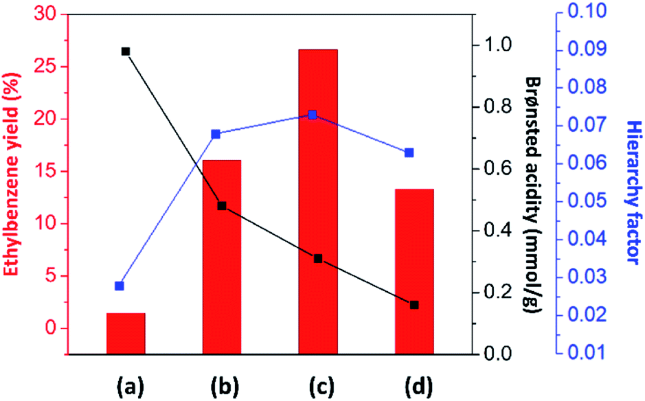 | ||
| Fig. 6 Relationship between the ethylbenzene yield (%) and the catalyst properties in terms of the amount of Brønsted acidic sites and the hierarchy factor of (a) mordenite, (b) MOR@ZSM-5(SS), (c) MOR@ZSM-5(CS), and (d) ZSM-5-NS. | ||
In the case of zeolite composites, the ethylbenzene yield is increased when compared to that of pure zeolites. However, the ethylbenzene yield over MOR@ZSM-5(SS) is not significantly improved with respect to the ZSM-5 nanosheet even though it has a higher Brønsted acid amount. This can be directly related to its morphology, in which some parts of mordenite are still exposed and can drive the formation of ethylene and coke. Interestingly, with the complete overgrowth of ZSM-5 nanocrystals on the mordenite crystals (MOR@ZSM-5(CS)), the ethylbenzene yield is considerably enhanced due to the improved hierarchical porosity as well as the reasonable Brønsted acidity provided by the fully dispersed nanocrystalline ZSM-5 on the entire area of the mordenite surfaces. Mordenite surfaces can serve as the supporting material† for nanocrystalline ZSM-5 to grow and disperse on and eventually, highly dispersed nanocrystalline ZSM-5 layer can be achieved via repeated ZSM-5 crystallization (Fig. 2(b and d)).
Interestingly, although conventional mordenite itself does not seem to be very selective for benzene alkylation due to its micropores and very high acidity, it can contribute to the enhanced catalytic activity of the overgrown zeolite composites owing to the modified hierarchical porosity and acidity of the composites. Therefore, the above results emphasize the crucial roles of the engineering of the zeolite surface via the overgrowth of nanocrystalline ZSM-5 on mordenite to control the catalyst properties with the view of improving the hierarchy factor and obtaining reasonable acidity to fine-tune the product distribution in the alkylation of benzene. Moreover, the MFI and MOR frameworks as well as the morphology of the synthesized composites are still preserved after being used in the reaction for 24 h (Fig. S8†).
Coke formation
To analyze the formation of coke species during benzene alkylation, O2-TPO profiles of all the spent catalysts at 24 h of TOS were recorded, which display oxidation peaks at different temperatures centered at about 150–200 °C, 400–450 °C, and 500–600 °C, corresponding to the oxidation of carbonate species,73 more hydrogenated coke species, which are likely aliphatic (coke I), and more carbonaceous coke species, which are likely aromatics (coke II) (Fig. 7 and Table S3†).81,82 Usually, coke I having a higher H/C ratio is deposited less selectively in the macro/mesopores, whereas coke II having a lower H/C ratio is deposited in the micropores undergoing diffusional restriction and/or outside the zeolite crystals.82 Therefore, the intense peak at about 500–600 °C in the TPO profiles suggests that coke species in all the spent catalysts is mainly present in the form of aromatics.83 Interestingly, the intense peak in the TPO profile of MOR@ZSM-5(SS) splits into two different peaks, indicating the sequential oxidation of coke deposited at different locations,84 which are likely the micropores and the external surfaces. In addition, it can be clearly observed that the oxidation temperature of the aromatic species shifts to higher temperature for spent mordenite when compared to ZSM-5-NS, demonstrating that coke deposited on mordenite is likely located within the micropores and is more difficult to be removed.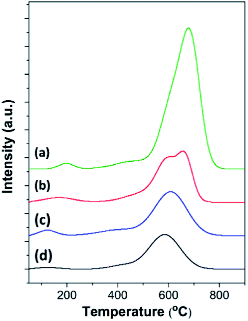 | ||
| Fig. 7 O2-TPO profiles of the spent catalysts: (a) mordenite, (b) MOR@ZSM-5(SS), (c) MOR@ZSM-5(CS), and (d) ZSM-5-NS taken after the catalytic test for the alkylation of benzene with ethanol at 450 °C for 24 h. | ||
The amount of coke deposited on different catalysts was observed to be in the order mordenite > MOR@ZSM-5(SS) > MOR@ZSM-5(CS) > ZSM-5-NS. For example, lower coke formation on the zeolite composites is related to their lower acidity and higher fraction of mesopores contributed by low acidity hierarchical nanocrystalline ZSM-5. Among all the zeolite composites, MOR@ZSM-5(CS) shows the lowest coke formation due to its highest hierarchical porosity along with suitable acidity due to the overgrowth of ZSM-5 nanocrystals, thus confirming its highest catalytic performance in ethylbenzene production.
In addition, the nature of coke formed over different catalysts was investigated using Raman spectroscopy. Unfortunately, with the use of a 532 nm laser source, the spectral features can be obscured by fluorescence.85 However, all the spent catalysts exhibited typical Raman spectra dominated by two bands associated with extended carbonaceous species86 (Fig. S9†). Apart from the two main bands, the band at 1179 cm−1 was also observed and was reported to appear only in poorly organized carbonaceous compounds; however, its assignment is still the subject of controversy.86 Due to the overlapping bands, the main two peaks were deconvoluted into four Gaussian peaks with the following assignments: (i) 1382 cm−1, “the breathing mode” of disordered aromatic clusters (D1 band); (ii) 1505–1516 cm−1, out-of-plane defects of the aromatic domains with poor organization (D3 band); (iii) 1565–1582 cm−1, in-plane stretching of the sp2 carbons of the structured aromatic clusters or graphitic-like coke (G band); and (iv) 1610 cm−1, disordered aromatics (D2 band).87 The corresponding results of the deconvolution are summarized in Table S4.†
As shown in Fig. S9 and Table S4,† it can be observed that the G band of all the zeolite composites and the ZSM-5 nanosheet is narrower (i.e., smaller Gw) and shifts towards higher wavenumber compared (i.e., larger Gp) with that of mordenite, demonstrating that the coke deposited on the zeolite composites and the ZSM-5 nanosheet is more structured.81 Furthermore, the D1/G ratio is a useful parameter that can be correlated to the growth of carbonaceous species according to the Ferrari–Robertson expression:88
| D1/G = 0.55La2 | (4) |
As presented in Table S4,† the results reveal a higher coke particle size of the structured coke on the composites and ZSM-5 nanosheet than that on mordenite. According to the Raman results, the coke deposited on the ZSM-5 nanosheet is preferably located on the external surfaces and the particle size of the structured coke is larger. Meanwhile, the low capability of mordenite for sweeping alkylated aromatic compounds towards the exterior owing to its microporous structure can lead to a higher fraction of internal coke, as revealed by the higher oxidation temperature in the TPO profile. As a result, internal coke can block the active sites and subsequently hinder the catalytic performance. However, in the case of the incomplete overgrowth (MOR@ZSM-5(SS)), coke is deposited both within the micropores and on the external surfaces, as evidenced by the two different peaks at 500–600 °C in the O2-TPO profile (Fig. 7). Interestingly, in the case of the full coverage sample (MOR@ZSM-5(CS)), the coke particle size is a bit smaller than that of ZSM-5-NS and the oxidation temperature of aromatic coke species is close to that of ZSM-5-NS, suggesting that coke deposited on MOR@ZSM-5(CS) is preferably located on the external surfaces.
To further investigate the pore blockage by cokes and to confirm the location of the cokes, N2 physisorption was performed on the spent catalysts obtained after benzene alkylation at 450 °C for 24 h (Fig. S10†). The results show that the surface area as well as the pore volume of the spent catalysts decreased with respect to the fresh ones (Tables 1 and S5†). Noticeably, the surface area and the pore volume of mordenite are completely lost after the reaction at 450 °C for 24 h, as evidenced by a trace N2 uptake in the N2 isotherm (Fig. S10†). This result indicates complete pore blocking by the coke species and demonstrates that the coke formed on mordenite is the internal coke deposited within the micropores. In strong contrast to this, all the hierarchical zeolite samples (MOR@ZSM-5(SS), MOR@ZSM-5(CS), and ZSM-5-NS) still exhibit a reasonable surface area as well as a pore volume, suggesting that the coke formed on these samples does not severely block the pores of the zeolites and the coke species is likely the external coke located on the external surfaces of catalysts. Moreover, the loss of micropore volume of different spent catalysts is in the order: mordenite > MOR@ZSM-5(SS) > MOR@ZSM-5(CS) > ZSM-5-NS and this order is reverse of the coke particle size estimated from Raman spectroscopy (Table S4†), again confirming that coke deposited on the ZSM-5 nanosheet is preferably located on the external surfaces and thus, the coke particle size is large, whereas the coke formed on mordenite is the internal coke deposited within the micropores and has a small particle size.
Conclusively, with the improved external surface area as well as the hierarchical porosity and a suitable amount of the acidic sites, the composites show good anti-coking performance and bring about simultaneously high activity and stability.
Conclusions
To demonstrate the concept of design of hierarchical zeolite composites with two different incompatible frameworks so as to improve the catalytic performance of benzene alkylation with ethanol, in this study, a MOR@ZSM-5 zeolite composite with full coverage by nanocrystalline ZSM-5 has been successfully fabricated via repeated ZSM-5 crystallization on mordenite pretreated using TBAOH as the structure-directing agent. The complete overgrowth of nanocrystalline ZSM-5 on mordenite crystals cannot be achieved by using single-step crystallization. However, ZSM-5 partly overgrown on mordenite obtained from the first crystallization can induce the further growth of ZSM-5 nanocrystals on mordenite surfaces, which can serve as the supporting material for nanosized ZSM-5 deposition, thus, eventually leading to continuous nanocrystalline ZSM-5 coating over the entire mordenite surfaces. As a result, the synthesized composite with a complete coverage of nanocrystalline ZSM-5 on mordenite exhibits significantly improved hierarchical porosity as well as reasonable acidic density and strength due to fully dispersed ZSM-5 nanocrystals on the mordenite surfaces.Interestingly, the designed ZSM-5 overgrown on the mordenite composite can considerably enhance the catalytic performance for alkylation of benzene with ethanol in terms of benzene conversion and ethylbenzene selectivity compared to the corresponding isolated zeolites and the physically mixed composite. In addition, the main product obtained over the overgrown zeolite composite is different from that of the isolated mordenite and the ZSM-5 nanosheet, suggesting that the product distribution can be tuned via the fabrication of the completely overgrown zeolite composite. The improved catalytic performance of the designed composite is likely related to its morphology, in which the dispersion of small nanosized ZSM-5 crystals on the mordenite surfaces can lead to promoted hierarchical porosity, more accessibility of the active sites, and suitable acidic properties (e.g., density and strength). Moreover, the coke deposited on the designed composite is likely the exterior coke located at the external surfaces does not significantly affect the catalytic performance. As demonstrated above, the present study illustrates the advantages of the designed overgrown zeolite composite of two different incompatible frameworks for improving the external surface area as well as hierarchical porosity, adjusting the acidic properties, and eventually controlling the product selectivity in acid-catalyzed reactions such as the alkylation of benzene with ethanol.
Conflicts of interest
There are no conflicts to declare.Acknowledgements
This work was supported by the Vidyasirimedhi Institute of Science and Technology, TTSF research project supported by Thailand Toray Science Foundation, Thailand Research Fund (MRG6180099), and the Office of Higher Education Commission. In addition, this work has been partially supported by the National Nanotechnology Center (NANOTEC), NSTDA, Ministry of Science and Technology, Thailand, through its program of Research Network NANOTEC.References
- A. Corma, Chem. Rev., 1997, 97, 2373–2420 CrossRef CAS PubMed.
- M. E. Davis and R. F. Lobo, Chem. Mater., 1992, 4, 756–768 CrossRef CAS.
- C. S. Cundy and P. A. Cox, Chem. Rev., 2003, 103, 663–702 CrossRef CAS PubMed.
- T. Yokoi, H. Mochizuki, S. Namba, J. N. Kondo and T. Tatsumi, J. Phys. Chem. C, 2015, 119, 15303–15315 CrossRef CAS.
- A. Corma, Chem. Rev., 1995, 95, 559–614 CrossRef CAS.
- N. Y. Chen and W. E. Garwood, Catal. Rev., 1986, 28, 185–264 CrossRef CAS.
- K. Tanabe and W. F. Hölderich, Appl. Catal., A, 1999, 181, 399–434 CrossRef CAS.
- N. Rahimi and R. Karimzadeh, Appl. Catal., A, 2011, 398, 1–17 CrossRef CAS.
- J. Rouquerol, D. Avnir, C. W. Fairbridge, D. H. Everett, J. M. Haynes, N. Pernicone, J. D. F. Ramsay, K. S. W. Sing and K. K. Unger, Recommendations for the Characterization of Porous Solids (Technical Report), Pure Appl. Chem., 1994, 66, 1739 CAS.
- A. Corma, J. Catal., 2003, 216, 298–312 CrossRef CAS.
- J. C. Groen, W. Zhu, S. Brouwer, S. J. Huynink, F. Kapteijn, J. A. Moulijn and J. Pérez-Ramírez, J. Am. Chem. Soc., 2007, 129, 355–360 CrossRef CAS PubMed.
- M. Choi, K. Na, J. Kim, Y. Sakamoto, O. Terasaki and R. Ryoo, Nature, 2009, 461, 246–249 CrossRef CAS PubMed.
- J. Kim, M. Choi and R. Ryoo, J. Catal., 2010, 269, 219–228 CrossRef CAS.
- L.-H. Chen, X.-Y. Li, J. C. Rooke, Y.-H. Zhang, X.-Y. Yang, Y. Tang, F.-S. Xiao and B.-L. Su, J. Mater. Chem., 2012, 22, 17381–17403 RSC.
- W. Chaikittisilp, Y. Suzuki, R. R. Mukti, T. Suzuki, K. Sugita, K. Itabashi, A. Shimojima and T. Okubo, Angew. Chem., Int. Ed., 2013, 52, 3355–3359 CrossRef CAS PubMed.
- C. J. H. Jacobsen, C. Madsen, J. Houzvicka, I. Schmidt and A. Carlsson, J. Am. Chem. Soc., 2000, 122, 7116–7117 CrossRef CAS.
- Y. Tao, H. Kanoh, L. Abrams and K. Kaneko, Chem. Rev., 2006, 106, 896–910 CrossRef CAS PubMed.
- W. Wannapakdee, C. Wattanakit, V. Paluka, T. Yutthalekha and J. Limtrakul, RSC Adv., 2016, 6, 2875–2881 RSC.
- P. Dugkhuntod, T. Imyen, W. Wannapakdee, T. Yutthalekha, S. Salakhum and C. Wattanakit, RSC Adv., 2019, 9, 18087–18097 RSC.
- J. Shao, T. Fu, Z. Ma, C. Zhang, H. Li, L. Cui and Z. Li, Catal. Sci. Technol., 2019, 9, 6647–6658 RSC.
- Z. Chen, L. Dong, C. Chen, Y. Wang, Y. Wang, J. Zhang, W. Qian and M. Hong, Nanoscale, 2019, 11, 16667–16676 RSC.
- S. Mintova, J.-P. Gilson and V. Valtchev, Nanoscale, 2013, 5, 6693–6703 RSC.
- Y. Fang, F. Yang, X. He and X. Zhu, Front. Chem. Sci. Eng., 2019, 13, 543–553 CrossRef CAS.
- Q. Zhao, B. Qin, J. Zheng, Y. Du, W. Sun, F. Ling, X. Zhang and R. Li, Chem. Eng. J., 2014, 257, 262–272 CrossRef CAS.
- J. Kim, C. Jo, S. Lee and R. Ryoo, J. Mater. Chem. A, 2014, 2, 11905–11912 RSC.
- A. Inayat, I. Knoke, E. Spiecker and W. Schwieger, Angew. Chem., Int. Ed., 2012, 51, 1962–1965 CrossRef CAS PubMed.
- A. Sachse and J. García-Martínez, Chem. Mater., 2017, 29, 3827–3853 CrossRef CAS.
- P. Wuamprakhon, C. Wattanakit, C. Warakulwit, T. Yutthalekha, W. Wannapakdee, S. Ittisanronnachai and J. Limtrakul, Microporous Mesoporous Mater., 2016, 219, 1–9 CrossRef CAS.
- T. Yutthalekha, C. Wattanakit, C. Warakulwit, W. Wannapakdee, K. Rodponthukwaji, T. Witoon and J. Limtrakul, J. Cleaner Prod., 2017, 142, 1244–1251 CrossRef CAS.
- Y. Kim, J.-C. Kim, C. Jo, T.-W. Kim, C.-U. Kim, S.-Y. Jeong and H.-J. Chae, Microporous Mesoporous Mater., 2016, 222, 1–8 CrossRef CAS.
- L. Meng, B. Mezari, M. G. Goesten and E. J. M. Hensen, Chem. Mater., 2017, 29, 4091–4096 CrossRef CAS PubMed.
- Y. Shen, H. Li, X. Zhang, X. Wang and G. Lv, Nanoscale, 2020, 12, 5824–5828 RSC.
- Y. Bouizi, L. Rouleau and V. P. Valtchev, Microporous Mesoporous Mater., 2006, 91, 70–77 CrossRef CAS.
- D. Kong, J. Zheng, X. Yuan, Y. Wang and D. Fang, Microporous Mesoporous Mater., 2009, 119, 91–96 CrossRef CAS.
- A. Lombard, A. Simon-Masseron, L. Rouleau, A. Cabiac and J. Patarin, Microporous Mesoporous Mater., 2010, 129, 220–227 CrossRef CAS.
- J.-H. Kim, A. Ishida, M. Okajima and M. Niwa, J. Catal., 1996, 161, 387–392 CrossRef CAS.
- S. Zheng, H. R. Heydenrych, A. Jentys and J. A. Lercher, J. Phys. Chem. B, 2002, 106, 9552–9558 CrossRef CAS.
- C. Liu, X. Gao, Z. Zhang, H. Zhang, S. Sun and Y. Deng, Appl. Catal., A, 2004, 264, 225–228 CrossRef CAS.
- Y. Lv, X. Qian, B. Tu and D. Zhao, Catal. Today, 2013, 204, 2–7 CrossRef CAS.
- A. Ghorbanpour, A. Gumidyala, L. C. Grabow, S. P. Crossley and J. D. Rimer, ACS Nano, 2015, 9, 4006–4016 CrossRef CAS PubMed.
- K. Miyake, Y. Hirota, K. Ono, Y. Uchida, S. Tanaka and N. Nishiyama, J. Catal., 2016, 342, 63–66 CrossRef CAS.
- F. Goodarzi, I. P. Herrero, G. N. Kalantzopoulos, S. Svelle, A. Lazzarini, P. Beato, U. Olsbye and S. Kegnæs, Microporous Mesoporous Mater., 2020, 292, 109730 CrossRef CAS.
- M. Razavian and S. Fatemi, Microporous Mesoporous Mater., 2015, 201, 176–189 CrossRef CAS.
- X. Li, F. Rezaei, D. K. Ludlow and A. A. Rownaghi, Ind. Eng. Chem. Res., 2018, 57, 1446–1453 CrossRef CAS.
- J. Zheng, G. Wang, M. Pan, D. Guo, Q. Zhao, B. Li and R. Li, Microporous Mesoporous Mater., 2015, 206, 114–120 CrossRef CAS.
- Q. Zhang, C. Li, S. Xu, H. Shan and C. Yang, J. Porous Mater., 2013, 20, 171–176 CrossRef CAS.
- Y. Fan, D. Lei, G. Shi and X. Bao, Catal. Today, 2006, 114, 388–396 CrossRef CAS.
- S. Liu, H. Zhang, H. Chen, Z. Chen, L. Zhang, J. Ren, X. Wen, Y. Yang and Y.-W. Li, Catal. Sci. Technol., 2020, 10, 1281–1291 RSC.
- Y. Bouizi, I. Diaz, L. Rouleau and V. P. Valtchev, Adv. Funct. Mater., 2005, 15, 1955–1960 CrossRef CAS.
- J. Zheng, Q. Zeng, Y. Zhang, Y. Wang, J. Ma, X. Zhang, W. Sun and R. Li, Chem. Mater., 2010, 22, 6065–6074 CrossRef CAS.
- Y. Bouizi, L. Rouleau and V. P. Valtchev, Chem. Mater., 2006, 18, 4959–4966 CrossRef CAS.
- D. V. Vu, M. Miyamoto, N. Nishiyama, S. Ichikawa, Y. Egashira and K. Ueyama, Microporous Mesoporous Mater., 2008, 115, 106–112 CrossRef CAS.
- Z. Shen, C. Ma, J. He, D. Wang, H. Sun, Z. Zhu and W. Yang, Appl. Catal., A, 2019, 577, 20–27 CrossRef CAS.
- L. Zhang, Z.-X. Jiang, Y. Yu, C.-S. Sun, Y.-J. Wang and H.-Y. Wang, RSC Adv., 2015, 5, 55825–55831 RSC.
- Z. Xu, J. Li, W. Qian, H. Ma, H. Zhang and W. Ying, RSC Adv., 2017, 7, 54866–54875 RSC.
- V. R. Vijayaraghavan and K. J. A. Raj, J. Mol. Catal. A: Chem., 2004, 207, 41–50 CrossRef CAS.
- J. Gao, L. Zhang, J. Hu, W. Li and J. Wang, Catal. Commun., 2009, 10, 1615–1619 CrossRef CAS.
- C. Martínez and A. Corma, Coord. Chem. Rev., 2011, 255, 1558–1580 CrossRef.
- B. Zhang, Y. Ji, Z. Wang, Y. Liu, H. Sun, W. Yang and P. Wu, Appl. Catal., A, 2012, 443–444, 103–110 CrossRef CAS.
- D. Wang, C.-M. Wang, G. Yang, Y.-J. Du and W.-M. Yang, J. Catal., 2019, 374, 1–11 CrossRef CAS.
- T. Odedairo and S. Al-Khattaf, Catal. Today, 2013, 204, 73–84 CrossRef CAS.
- M. Yamamura, K. Chaki, T. Wakatsuki, H. Okado and K. Fujimoto, Zeolites, 1994, 14, 643–649 CrossRef CAS.
- Y. Jin, Y. Li, S. Zhao, Z. Lv, Q. Wang, X. Liu and L. Wang, Microporous Mesoporous Mater., 2012, 147, 259–266 CrossRef.
- Y. Yang, J. Ding, C. Xu, W. Zhu and P. Wu, J. Catal., 2015, 325, 101–110 CrossRef CAS.
- M. M. J. Treacy and J. B. Higgins, Collection of Simulated XRD Powder Patterns for Zeolites, Published on Behalf of The Structure Commission of The International Zeolite Association, Elsevier, 5th revised edn, 2007 Search PubMed.
- J. C. Jansen, F. J. van der Gaag and H. van Bekkum, Zeolites, 1984, 4, 369–372 CrossRef CAS.
- Y. Wang, J. Ma, F. Ren, J. Du and R. Li, Microporous Mesoporous Mater., 2017, 240, 22–30 CrossRef CAS.
- K. Sing, Colloids Surf., A, 2001, 187–188, 3–9 CrossRef CAS.
- P. Schneider, Appl. Catal., A, 1995, 129, 157–165 CrossRef CAS.
- J. Pérez-Ramírez, D. Verboekend, A. Bonilla and S. Abelló, Adv. Funct. Mater., 2009, 19, 3972–3979 CrossRef.
- J. Klinowski, Prog. Nucl. Magn. Reson. Spectrosc., 1984, 16, 237–309 CrossRef CAS.
- V. N. Shetti, J. Kim, R. Srivastava, M. Choi and R. Ryoo, J. Catal., 2008, 254, 296–303 CrossRef CAS.
- T. Imyen, W. Wannapakdee, J. Limtrakul and C. Wattanakit, Fuel, 2019, 254, 115593 CrossRef CAS.
- P. Waller, Z. Shan, L. Marchese, G. Tartaglione, W. Zhou, J. C. Jansen and T. Maschmeyer, Chem.–Eur. J., 2004, 10, 4970–4976 CrossRef CAS PubMed.
- L. H. Ong, M. Dömök, R. Olindo, A. C. van Veen and J. A. Lercher, Microporous Mesoporous Mater., 2012, 164, 9–20 CrossRef CAS.
- S. Schallmoser, T. Ikuno, M. F. Wagenhofer, R. Kolvenbach, G. L. Haller, M. Sanchez-Sanchez and J. A. Lercher, J. Catal., 2014, 316, 93–102 CrossRef CAS.
- Y. Du, H. Wang and S. Chen, J. Mol. Catal. A: Chem., 2002, 179, 253–261 CrossRef CAS.
- A. Corma, F. J. Llopis, C. Martínez, G. Sastre and S. Valencia, J. Catal., 2009, 268, 9–17 CrossRef CAS.
- S. K. Saxena and N. Viswanadham, Appl. Mater. Today, 2016, 5, 25–32 CrossRef.
- T. K. Phung, L. Proietti Hernández, A. Lagazzo and G. Busca, Appl. Catal., A, 2015, 493, 77–89 CrossRef CAS.
- E. Epelde, M. Ibañez, A. T. Aguayo, A. G. Gayubo, J. Bilbao and P. Castaño, Microporous Mesoporous Mater., 2014, 195, 284–293 CrossRef CAS.
- M. Ibáñez, M. Artetxe, G. Lopez, G. Elordi, J. Bilbao, M. Olazar and P. Castaño, Appl. Catal., B, 2014, 148–149, 436–445 CrossRef.
- A. T. Aguayo, P. Castaño, D. Mier, A. G. Gayubo, M. Olazar and J. Bilbao, Ind. Eng. Chem. Res., 2011, 50, 9980–9988 CrossRef CAS.
- X. Xian, C. Ran, C. Nai, P. Yang, S. Zhao and L. Dong, Appl. Catal., A, 2017, 547, 37–51 CrossRef CAS.
- D. S. Wragg, R. E. Johnsen, M. Balasundaram, P. Norby, H. Fjellvåg, A. Grønvold, T. Fuglerud, J. Hafizovic, Ø. B. Vistad and D. Akporiaye, J. Catal., 2009, 268, 290–296 CrossRef CAS.
- J. A. Botas, D. P. Serrano, A. García, J. de Vicente and R. Ramos, Catal. Today, 2012, 195, 59–70 CrossRef CAS.
- Á. Ibarra, A. Veloso, J. Bilbao, J. M. Arandes and P. Castaño, Appl. Catal., B, 2016, 182, 336–346 CrossRef.
- A. C. Ferrari and J. Robertson, Phys. Rev. B: Condens. Matter Mater. Phys., 2000, 61, 14095–14107 CrossRef CAS.
Footnote |
| † Electronic supplementary information (ESI) available: SEM images, TEM images, SEM-EDS elemental point analyses, BJH pore size distribution, 27Al MAS NMR spectra, catalytic performance in terms of reaction conversion and product selectivity, XRD patterns of spent catalysts, Raman spectra with representative parameters, and the coke content in spent catalysts. See DOI: 10.1039/d0na00391c |
| This journal is © The Royal Society of Chemistry 2020 |