
 Open Access Article
 This Open Access Article is licensed under a Creative Commons Attribution-Non Commercial 3.0 Unported Licence
Carbon nanotube columns for flow systems: influence of synthesis parameters†
Jonathan
Quinson‡§
 *a,
Thomas
Bottein‡¶
a,
Frank
Dillon
a,
Seyyed Shayan
Meysami||
a and
Nicole
Grobert
ab
*a,
Thomas
Bottein‡¶
a,
Frank
Dillon
a,
Seyyed Shayan
Meysami||
a and
Nicole
Grobert
ab
aDepartment of Materials, University of Oxford, Parks Road, OX1 3PH Oxford, UK. E-mail: jonathan.quinson@chem.ku.dk
bWilliams Advanced Engineering, Grove, Oxfordshire, OX12 0DQ, UK
First published on 19th November 2020
Abstract
Flow reactors are expected to play an increasingly important role in the production of chemicals. A simple carbon-based scaffold to easily develop flow systems is here detailed. Using a chemical vapour deposition technique, the controlled in situ growth of vertically aligned (VA) multi-wall carbon nanotubes (MWCNTs) into quartz columns with 2 mm inner diameter is achieved. Several of the described MWCNT columns (CNCs) can be produced at a time. The influence of synthesis parameters on the formation of these VA-MWCNT scaffolds is reported and discussed (e.g. injection time of the precursor, carrier gas flow rate, inner diameter and length of the quartz column, position in the furnace during synthesis). Raman spectroscopy, optical microscopy, scanning and transmission electron microscopy are used to assess the coverage of the inner channel of the quartz column with VA-MWCNTs and their overall quality. The length of the CNCs together with the carrier gas flow rate are found to be key parameters to control the MWCNT length profile within the CNCs. Fluoresceinamine molecules and platinum nanoparticles are successfully immobilised within these MWCNT scaffolds. The benefits of the CNCs for flow system design are summarised as the controlled filling with MWCNTs makes the detailed CNCs versatile scaffolds for flow catalysis and filtration.
1. Introduction
The benefits of flow systems over batch processes in the chemical sciences are multiple: continuous operation, better control over experimental parameters, minimised waste and energy, etc.1–4 Due to their outstanding mechanical, chemical and surface properties, carbon nanotubes (CNTs) have attracted interest for various flow systems like filters,5 membranes,6,7 or chromatography.8,9 However, their implementation in flow catalysis10–12 is more limited despite being intensively investigated as supports for various catalysts13 including particles,14,15 molecules16 or enzymes,17–20 and for various chemical reactions. The relatively limited use of CNTs in flow systems can be inferred to the challenging dispersion of CNTs21 especially in aqueous solutions and the related complex processing.21,22 In addition, the integration of CNTs in flow devices using classical methods is not straightforward and may require multiple steps including high pressures, e.g. for packing a column,23 substrate pre-treatments11 and/or the use of sacrificial templates and etching agents.12By chemical vapour deposition (CVD) methods, CNTs can be grown directly on a substrate as vertically aligned (VA) ‘forests’ or ‘carpets’.10 A simple approach to fill a column with VA-CNTs is to use the column itself as reactor. This approach was reported to develop stationary phases in chromatography.24,25 This is conceptually close to the development of ‘inner wall-functionalised’ flow reactors.11,26,27 The direct growth of CNTs within a column does not require any supportive binder or frit28 to immobilise CNTs since VA-CNTs are typically in good mechanical contact with the surface they are grown on.10 However, in most reports, the hydrocarbon flow required to grow the CNTs is forced to pass through the column during synthesis. As a consequence, only one column is obtained at a time.5,9,24,25,29 Mini reactors (channel size between 0.5 and 2 mm) compared to micro reactors (channel of size inferior to 0.5 mm)26 require lower pressure to pass a flow through under operating conditions. Mini-rector systems also appear more attractive to synthesise VA-CNTs in a column by CVD without high pressure requirement.
To simply transpose CNTs to flow devices, a simple and versatile approach to obtain multi-wall CNT (MWCNTs) columns (CNCs) was introduced.30 It consists in growing VA-MWCNTs31 into 2 mm inner diameter (ID) column-like quartz substrates. So doing, the challenging dispersion of the CNTs is avoided, several columns can be obtained in a single experiment, and there is no need for any sacrificial template or etching step. Moreover the CNCs obtained are readily suitable scaffolds for flow catalysis.30 In addition, it offers the benefits of miniaturised flow systems27,32,33 such as continuous production, possibility of working with small volumes and hence higher concentrations, whilst minimizing waste and energy consumption. Since controlling CNT growth into substrate with column-like geometries is important for optimising CNC filling and further applications, the influence of various experimental parameters over VA-MWCNT length profile and graphitic structure in a CNC is here detailed. The properties and benefits of CNCs for flow system design are highlighted.
2. Experimental
2.1. Chemicals
Ethanol (CH3OH, 99.8%, Fisher Scientific), toluene (C6H5CH3, 99.9%, Fluka), fluoresceinamine (6-aminofluorescein, ≥90%, Aldrich), chloroplatinic acid hexahydrate (H2PtCl6·6H2O, ACS reagent, Sigma-Aldrich), formic acid (98%, Fluka), sulfuric acid (H2SO4, 98%, Fisher Scientific) were all used as received. Ferrocene (C10H10Fe, 98%, Aldrich) was resublimed at 90 °C prior to use. Argon (Ar, 99.99%), was obtained from BOC. Ultra-high purity water (Millipore MilliQ, 18 MΩ cm) was used for all aqueous solutions.2.2. CNC synthesis
VA-MWCNTs were synthesised using aerosol assisted chemical vapour deposition via a previously reported general method.20,34,35 Briefly, a precursor mixture of toluene and ferrocene (5 wt%) was used together with argon as a carrier gas at a flow rate of 2500 sccm, unless otherwise specified. Syntheses were run at 800 °C. Quartz tubes (Robson Scientific, UK) with 1 mm, 2 mm or 4 mm ID and outer diameters 8 mm, 4 mm and 6 mm respectively were used as column substrates. These columns were cleaned by sonication for at least one minute in ethanol prior to use. Without any other pre-treatment, they were positioned in a quartz tube of 21 mm ID playing the role of the reactor during synthesis. The columns were positioned in such a way that one extremity of the column (the IN extremity detailed below) was placed at 17, 23, 27, 29, 39 or 45 cm inside the furnace in the direction of the gas flow during synthesis, as detailed in Fig. S1 in ESI.† The longest dimension of the column was aligned with the axis of the reactor and several columns could be placed at a same position. Up to three columns could be placed per position and so up to twenty five CNCs can be obtained per experiment. Post-synthesis, the furnace was left to cool down to below 300 °C under an argon atmosphere before collecting the columns covered with a black deposit.2.3. CNC cross-sections
VA-MWCNT length profiles in CNCs were measured after achieving cross sections of the quartz columns. A diamond pen or a tungsten carbide blade was used to scratch the outer part of the CNC and the cross section made by simply ‘snapping’ the CNC at the desired position. To un-ambiguously identify the columns and to define the entrance (IN) and exit (OUT) of a column relative to the flow of carrier gas during MWCNT growth, columns were marked at one extremity with a diamond pen. Positions along the CNCs are defined relative to the extremity facing the hydrocarbon flow during synthesis, define as position 0 cm (entrance, IN). The other extremity of the column, not facing directly the flow of hydrocarbon during synthesis, is defined as the exit (OUT). This is schematically represented in Fig. S2.† VA-MWCNT length profiles along a column were obtained by measuring the VA-MWCNT length on various cross-sections of a same column.2.4. CNC characterisation
The CNCs were characterised by scanning electron microscopy (SEM, Jeol 840F operated at 5 kV), transmission electron microscopy (TEM Jeol 2000FX operated at 200 kV) and optical microscopy (VMS-004 Deluxe microscope, with a ×10 objective). Samples for SEM were placed in specially designed SEM holders. TEM samples were prepared by dispersing MWCNTs collected in a CNC by sonication in ethanol for five minutes prior to depositing few drops of the solution on a carbon TEM grid. Raman spectroscopy was performed with a JY Horiba Labram Aramis imaging confocal Raman microscope (532 nm laser excitation and using a ×50 objective) on CNC cross sections. Energy dispersive X-ray spectroscopy (EDS) was performed with a Hitachi TM-3000 table top SEM operated at 15 kV and equipped with an EDS detector. The VA-MWCNT length profiles inside the CNCs were obtained using images recorded with ×10 or ×50 optical lenses. Selected areas were studied by SEM to confirm the results with higher resolution. It was found that the analysis using images recorded with a simple optical microscope was sufficient for the purposes of this study.2.5. Fluoresceinamine adsorption
A saturated solution of fluoresceinamine was prepared in water. The fluoresceinamine solution was then flushed through CNCs by 10 uptake–outtake cycles with a syringe whereby the needle was made of a CNC, Fig. S3.† The CNCs were left in the fluoresceinamine solution for 12 to 36 hours. Columns used were 1 cm or 2 cm long. The columns were then thoroughly washed with ultra-high purity water and a cross section performed for characterisation.2.6. Platinum salt chemical reduction
Platinum (Pt) nanoparticles were deposited by chemical reduction of a platinum salt.36 To do so, CNCs obtained with a synthesis time of 90 minutes were left in concentrated sulfuric acid for 24 hours and subsequently thoroughly washed with high purity water. The CNCs were then left for another 24 hours in 10 mL of an aqueous solution of H2PtCl6·6H2O (21 mM) before 0.5 mL of formic acid were added. After further 12 hours, the samples were thoroughly washed with ultra-high purity water. During all steps a magnetic stirrer was used to stir the solutions. Cross sections were then performed for imaging and analysis.3. Results and discussion
3.1. Multi-wall carbon nanotubes columns (CNCs): general synthesis and characterisation
The flow chart of the process to obtain CNCs is illustrated in Fig. S4.† During aerosol assisted CVD, all surfaces exposed to the precursor (here toluene and 5 wt% ferrocene) in the hot region of the furnace are covered with CNTs during synthesis. This includes the external surfaces of the quartz column with 2 mm diameter used here as substrate. After synthesis, the quartz columns are covered with a black deposit. Removing this black deposit from the outside surface of the column is achieved by simply mechanically scratching the surface. A schematic representation of a quartz column then obtained is given in Fig. 1a. It is possible to see light through the columns. This is a first evidence that the columns are not blocked by VA-MWCNTs. The inner part of the column is also covered with a black deposit. | ||
| Fig. 1 (a) Schematic representation of a CNC and associated sections. (b) SEM micrograph of a cross section performed in the middle of a CNC showing VA-MWCNTs. The quartz surface appears as white background, the MWCNTs are dark grey and the black inner channel is due to the partial filling of the column. (c) SEM micrograph of a longitudinal section of a CNC showing an inner channel free of MWCNTs. (d) Higher magnification SEM micrograph. (e) Raman spectrum and (f) TEM micrograph of MWCNTs grown inside the CNCs. | ||
SEM micrographs of the structures grown in the middle of a column after cross and longitudinal sections, see Fig. 1a, are reported in Fig. 1b and c, respectively. The typical ‘forest’ or ‘carpet’ geometry expected for VA-MWCNTs grown by aerosol assisted CVD is observed. The MWCNTs grow perpendicular to the inner diameter surface of the quartz column. This is consistent with reports of VA-MWCNTs growing perpendicular to flat substrates.11,35 The quartz column appears as a white background in the SEM cross section in Fig. 1b whereas the MWCNTs are dark grey. The black centre in the middle of the image corresponds to a zone without material in agreement with Fig. 1c. The full coverage of the quartz column inner wall is confirmed since there is no part of the column without MWCNTs. An inner channel without material is formed since the VA-MWCNTs are not grown long enough to fill the column inner diameter. The full coverage but partial filling account for the ability to see-through CNCs despite VA-MWCNT deposition.
A higher magnification SEM micrograph of the structures grown is reported in Fig. 1d. It further confirms that the structures developed are indeed tubular nanomaterials. The MWCNT structure is equally confirmed by Raman spectroscopy performed on various cross sections of CNCs for which a typical spectrum is reported in Fig. 1e. The three expected characteristics Raman peak of MWCNTs37 around 1340 cm−1 (D peak), 1565 cm−1 (G peak) and 2680 cm−1 (2D peak) are observed for all samples on all cross sections. Finally, a transmission electron microscope (TEM) micrograph of the materials collected within a column is reported in Fig. 1f. TEM analysis confirms a hollow tube-like material grown into the column with a majority of tubes showing an inner diameter (whiter part of the tube) between 8 and 20 nm with thick outer walls (darker part of the tubes) leading to an outer diameter in the range 25–60 nm. The MWCNTs obtained do not differ from VA-MWCNTs obtained by similar approach but without using a quartz column as a substrate.20,34,38 All the presented characterisations, together with picture reported in Fig. S5,† confirm full coverage of the inner channel of the column with VA-MWCNTs.
3.2. Control over CNC filling: a parametric study
To control the filing of CNCs with VA-MWCNTs, several parameters were investigated and their effects on the length and graphitic structure of the MWCNTs inside the columns assessed. The diameter of the columns (e.g. 1, 2, 4 mm ID) is found not to be a limiting factor to grow VA-MWCNTs within the CNCs. In order to develop mini reactors26 a detailed study was performed on columns with 1 mm and 2 mm ID. Using flat quartz substrate, we documented the influence of the position of substrates inside the furnace and how this affects the properties of the as produced VA-MWCNTs.34 The influence of the position of the columns quartz substrate in the furnace was then studied. The position in the furnace where MWCNT length within the CNCs was the most homogeneous were located between 23 and 29 cm into the furnace. The other experimental parameters investigated and found to have a pronounced impact on the CNT growth – therefore on the filling of the CNCs – are (1) the time of precursor injection during MWCNT synthesis, (2) the length of the quartz column used as substrate and (3) the flow rate of carrier gas.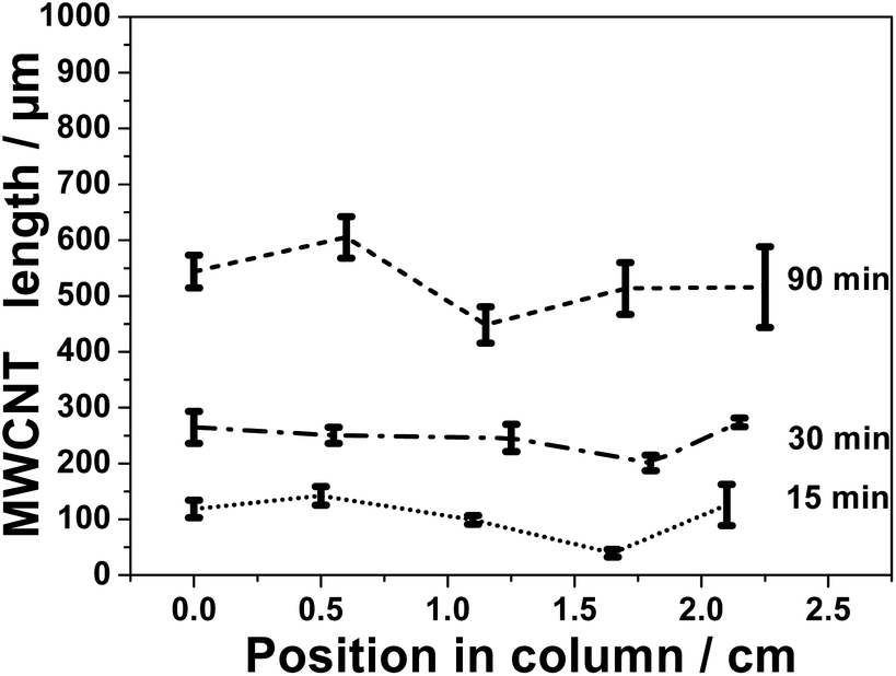 | ||
| Fig. 2 Length profile of the VA-MWCNTs grown inside a 2 cm long 2 mm ID column as a function of the position into the column and as a function of the time of synthesis. The carrier gas flow rate was 2500 sccm and results obtained for a column used as substrate placed 29 cm inside the furnace. | ||
For time of synthesis longer than 90 minutes, the complete filling of the column could not be achieved (total length of the MWCNTs < 1000 μm, see also Fig. S6†). Nevertheless, MWCNTs longer than 500 μm are easily grown on most of the inner surface of the column with an injection time of 90 minutes. This means that more than 75% of the inner channel surface on a column cross section is made of MWCNTs. A time of 90 minutes was considered enough to achieve an optimal filling of the CNCs.
The same study using smaller 1 mm ID CNCs gives in-homogenous column filling. In particular the middle of the column is nearly free of VA-MWCNTs whereas entrance (IN) and exit (OUT) are usually completely filled, see Fig. S7.† Due to the small inner diameter of the column, the column core is blocked by VA-MWCNTs that can grow long enough to connect with the MWCNTs grown diametrically opposed, Fig. S8.† It is concluded that the best inner diameter for the column to develop mini rectors is 2 mm. The use of 1 mm ID columns was not studied in greater details to develop mini reactors. With 2 mm ID columns, for synthesis time of 150 minutes, CNCs with only their OUT extremity blocked are observed. In such case, VA-MWCNTs were protruding out of the column, see Fig. S9.† Whilst such ‘blockage’ was noticed to hinder liquids to pass through the column, these CNCs might still be relevant for high pressure filtration.
 | ||
| Fig. 3 Length profiles of VA-MWCNTs grown inside quartz columns as a function of the position in the column for 2, 3 and 4 cm long columns with 2 mm ID. The carrier gas flow rate was 2500 sccm and the synthesis time was 90 minutes. All column-substrates were located between 23 and 29 cm within the furnace. | ||
For 1 mm ID CNCs, the filling is generally inhomogeneous, and the extremities of the columns are usually more filled than the middle of the column, see Fig. S10 and S11.† This trend in the filling has been observed for various experimental conditions and for a number of experiments detailed in ESI.† Therefore, it is concluded that 2 cm is the optimal length to prepare CNCs.
3.2.3.1. Fixed carrier gas flow rate. Three different carrier gas flow rates were investigated: 1000, 2500 and 5000 sccm. In the case of 2500 sccm a better global filling is observed compared to the case of 1000 sccm, as reported in Fig. 4 and S12.† In the plain set of data obtained with 2500 sccm flow of carrier gas, the shortest VA-MWCNTs are ca. 300 μm whereas for 1000 sccm on the dashed set of data they are ca. 50 μm. In both cases, the longest VA-MWCNTs observed are around 700 μm in length. For 5000 sccm, the zone in the furnace giving more homogeneous CNC filling is between 39 and 45 cm, Fig. S13.† However, while consuming more precursors for a same time of hydrocarbon injection, a flow rate of 5000 sccm does not bring any significant advantage over the control on CNC filling.
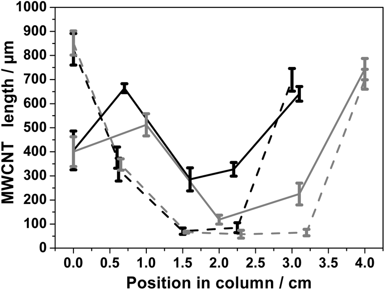 | ||
| Fig. 4 Length profile of the VA-MWCNTs grown into columns as a function of the position inside 2 mm ID and 3 cm (black) or 4 cm (grey) long columns. The carrier gas flow rate was 1000 sccm (dashed) or 2500 sccm (plain) and results obtained for columns placed at 27 cm within the furnace. The synthesis time was 90 minutes. | ||
For experiments performed with flow rates of 2500 sccm, the VA-MWCNTs formed at the IN position (0 cm) are shorter than those at the OUT position, Fig. 3 and plain line in Fig. 4. This difference is more pronounced for CNC with a column length longer than 2 cm. The opposite observation is made for the experiments carried out with a carrier gas flow rate of 1000 sccm, see dashed lines in Fig. 4. In experiments conducted with a flow rate of 1000 sccm, the VA-MWCNTs are longer at the column gas inlet (IN) than at the opposite end (OUT). Therefore, the carrier gas flow rate is an important parameter to control the VA-MWCNT properties along the column. Possible reasons for this observation are discussed in Section 3.4.
3.2.3.2. Change in the carrier gas flow rate. Since 2500 and 1000 sccm lead to a reasonable filling of the CNCs, the carrier gas flow rate was changed during synthesis in order to optimize CNC filling further. Results are shown in Fig. 5. A minimum VA-MWCNT length around 600 μm for a maximum length around 700 μm is achieved for CNCs placed at 23 cm within the furnace. With 2 mm ID and 2 cm long columns, the MWCNTs length profile is more homogenous across the column. However this approach of changing flow rates during synthesis, does not result in better filling of longer columns, Fig. S14.† An important difference when a change of flow rate of carrier gas is performed, compared to a case without flow rate change, is the shape of the grown VA-MWCNTs. SEM imaging of a CNC cross section obtained with a flow change during synthesis, reveal that the shape of the VA-MWCNTs forest is no longer concentric with respect to the column axis, Fig. 5b, and as it was the case with a fixed value for the career gas flow rate, see Fig. 1b. This observation adds evidence to the importance of controlling the flow rate the process in order to control the nature of the CNC filling. It is, however, beyond the scope of this work to further study and firmly conclude on what drove this unusual geometry of the VA-MWCNT deposit prepared with different flow rates during synthesis. See Section 3.4 for further discussion.
 | ||
| Fig. 5 (a) Length profile VA-MWCNTs grown inside a 2 cm long 2 mm ID column as a function of the position in the column. A change of carrier gas flow was performed during synthesis. The precursor injection time was 20 minutes at 2500 sccm followed by 100 minutes at 1000 sccm. Samples were placed at 23 cm (black solid line) or 29 cm (grey, dashed line) in the furnace. (b) SEM micrograph of a cross section of a 2 mm ID CNC obtained during a synthesis where the carrier gas flow rate was changed from 2500 to 1000 sccm. | ||
3.3. Controlling VA-MWCNT graphitisation in CNC
Raman spectra of MWCNTs typically display three peaks: D, G and 2D peak at 1340, 1565 and 2675 cm−1 respectively, as illustrated already in Fig. 1e. The ‘quality’, i.e. graphitisation, of a MWCNT can be evaluated by the intensity (I) ratio of the D and G peak. In simple terms, a small ID/IG intensity ratio is a result of low defect MWCNT.38 By systematically recording Raman spectra at the IN and OUT positions on various CNCs, it is observed for number of experimental conditions (including different inner diameter columns) that the ID/IG ratio is statistically different at those two positions on a same CNC. This observation is illustrated in Fig. 6 for 2 mm ID 4 cm long column: the Raman spectra at the IN positions shows a relatively higher D peak intensity and smaller 2D peak intensity compared to the spectra recorded at the OUT position. The ID/IG ratio is then significantly higher at the IN than the OUT position. The intensity ratios obtained at cross sections of the columns were however statistically not significantly different from IN or OUT positions and so were not investigated further.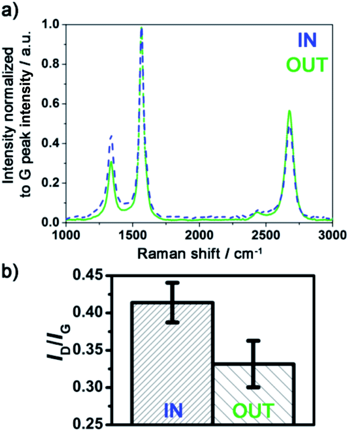 | ||
| Fig. 6 (a) Raman spectra at the IN and OUT position of a 2 mm ID and 4 cm long column. Synthesis was performed with a carrier gas flow rate of 2500 sccm for 90 minutes. The substrate was placed 27 cm within the furnace. (b) Representative Raman intensity ratio ID/IG at the IN and OUT positions of the CNC. | ||
The difference between the IN and OUT position is to be correlated with the difference in VA-MWCNT length observed at these positions for the same CNC, for which the MWCNT length profile is reported in Fig. 4 (solid dark line). The VA-MWCNT length is significantly longer at the OUT than the IN position. This combination of lower ID/IG value and longer VA-MWCNTs at the OUT positions compared to higher ID/IG value and shorter VA-MWCNTs at the IN positions was almost always observed for samples produced with a carrier gas flow rate of 2500 sccm. In contrast, for samples produced at flow rates of 1000 sccm, the inverse trend is observed: the VA-MWCNTs ID/IG ratio are smaller at the IN rather than the OUT position of the CNC, Fig. S15,† whilst the VA-MWCNTs are now longer at the entrance than the exit, e.g. dashed line in Fig. 4. A flow of 5000 sccm did not lead to significant difference in the ID/IG ratio at the IN or OUT positions.
3.4. Discussion
Since the VA-MWCNT length profiles are less homogeneous as the length of the column increases, Fig. 4, and the difference in length and graphitisation more pronounced for longer columns, Fig. 6, an experiment with a 10 cm long 1 mm ID was performed with a carrier gas flow rate of 2500 sccm, see Fig. S16.† For this set of experimental parameters, most of the column remained free of VA-MWCNTs. These results suggest that most of the hydrocarbon precursor flow does not go through the column efficiently, thus preventing catalyst particles deposition and VA-MWCNT formation inside the column. Nevertheless, in agreement with results presented in this study, the length of the VA-MWCNTs was longer at the OUT than the IN position and the ID/IG value lower at the OUT than the IN position. It is then likely that a change in the flow distribution at the IN and OUT position of the column happens, possibly a back flow phenomenon or a more turbulent flow at the OUT position. For a flow of 2500 sccm, this ‘perturbation’ in the flow induced by non-flat substrate is responsible for the growth of longer and more graphitic VA-MWCNTs at the OUT position of the CNC.The strong dependence of VA-MWCNT length and ID/IG values to the flow rate value of the carrier gas also supports the previous explanation. Depending on the carrier gas flow rate, different conditions for the formation of the catalyst particles responsible for VA-MWCNT nucleation and growth are likely induced at the IN and OUT positions, leading to different growth conditions, and hence resulting in different properties of the VA-MWCNTs grown in terms of length and graphitisation. This explanation also accounts for the different filling of the CNCs obtained with a flow change during synthesis, Fig. 5b. Changing the flow rate of carrier gas likely promotes different growth conditions along the column as the VA-MWCNTs form, and this could account for the slightly more homogenous filling observed. This finally account for the different length of MWCNTs observed in a same section of the column if a flow rate change is induced.
Moreover, VA-MWCNTs produced with flow rates of 2500 sccm not only exhibited different lengths and graphitisation, but also different oxidation behaviour, Fig. S17.† The VA-MWCNTs obtained on the part of the column closer to the OUT position show better oxidation resistance than VA-MWCNTs collected closer to the IN position. This can be related to the more graphitic structure of the MWCNTs that correlates with higher oxidation resistance.38 This result supports the different in nature of the MWCNTs grown at these different locations. This gives an example of a facile approach for tuning VA-MWCNTs properties by careful consideration of the substrate geometry together with the control of the carrier gas flow rate during synthesis.
3.5. CNCs: towards flow systems
CNCs were previously reported as suitable scaffolds for flow bio-catalysis.30 This section illustrates the relevance of CNCs for flow systems in more general terms, e.g. filtration and heterogeneous catalysis. Cross sections of the CNCs are performed without disconnecting the VA-MWCNTs from the quartz surface as observed in Fig. 1. This suggests a relatively strong mechanical link between the VA-MWCNTs and the column inner surface. As a consequence, the CNCs can withstand a flow of liquid passing through the column. This is confirmed by using a CNC as ‘needle’ for a syringe as reported in Fig. S3.† The liquid is passed through the CNC without noticeable loss of the VA-MWCNTs and with low pressure requirement (a simple syringe without pumps is enough). VA-MWCNTs were suggested to lead to more individualised nanotubes,9,24 possibly promoting better wettability28 as well as better flow distribution within the carbon scaffold.11,39 Another important property expected from MWCNT networks is to allow facile penetration and immobilisation of species. E.g. from an aqueous solution and so despite the hydrophobic nature of MWCNTs.22Fluoresceinamine has a Raman signature distinct from the MWCNT peaks.40,41 Optical images of a CNC extremities and cross section are reported in Fig. 7a–c as well as Raman spectra in Fig. 7d before and after exposure to fluoresceinamine. After exposure to a fluoresceinamine solution (detailed in the Experimental section), the presence of immobilised or trapped fluoresceinamine within the CNC carbon network is established by presence of a pronounced Raman feature at 1179 cm−1. The presence of fluoresceinamine in the carbon network is also marked by peaks at 1414, 1474, 1504 and 1634 cm−1. This is especially clear at both ends of the CNC in direct contact with the solution (fine line) but is also observed on a cross section within the column (bold line). The peak at 1340 cm−1 and 1565 cm−1 are characteristic of the MWCNTs (dotted line) in Fig. 7d. Similar results were obtained with CNC of different length. The Raman spectra recorded directly at both ends of the column as well as on cross sections performed in the middle of the column, reveal peaks characteristic of the probe molecule fluoresceinamine in all cases.
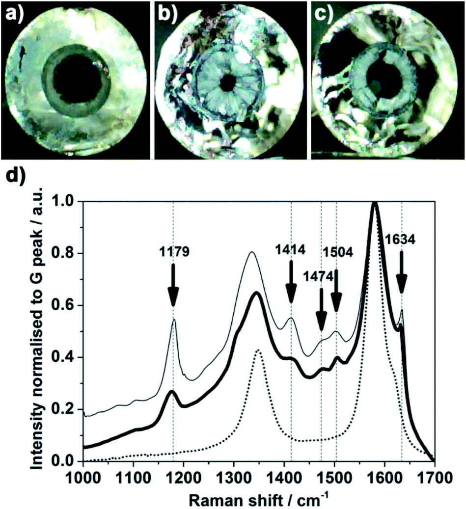 | ||
| Fig. 7 (a–c) Photographs of a 1 cm long 2 mm ID column. (a) and (c) are the extremities of the CNC. (b) is a cross section performed in the middle of the CNC. (d) On this same CNC, Raman spectra were recorded after exposure to a solution of fluoresceinamine: at one extremity of the CNC (fine line) and at a cross section in the middle of the CNC (bold line). The Raman features recorded at a cross section of a CNC before exposure to an aqueous solution of fluoresceinamine are also reported (fine dotted black line). The spectra were normalised to the intensity value of the G peak at 1565 cm−1. | ||
Platinum is a catalyst for several reactions and Pt nanoparticles have been reported in flow configuration after immobilisation in CNT forest for hydrosilylation reactions at 50 °C![[thin space (1/6-em)]](https://www.rsc.org/images/entities/char_2009.gif) 11 or hydrogenation at 27 bar.12 Pt nanoparticles are easily reduced chemically in situ within a CNC carbon network, see Experimental section for more details. In Fig. 8a, the whiter dots observed on the carbon network in the backscattered electron micrograph correspond to metal nanoparticles. The EDS data shown in Fig. 8a confirm the presence of Pt species. The iron signal is due residual iron catalysts particles in the MWCNT network.34 However, the presence of iron alone does not account for the density of white dots present in the SEM images. The presence of iron was shown previously to not prevent the use of the scaffolds for bio-catalysis.20,30 This observation can be attributed to the iron being mainly trapped within the tubes as it can be seen in Fig. 1f where darker features are attributed to iron nanoparticles located in the core of the MWCNTs. It must however be kept in mind that presence of iron may play a postitive or negative role in further applications.
11 or hydrogenation at 27 bar.12 Pt nanoparticles are easily reduced chemically in situ within a CNC carbon network, see Experimental section for more details. In Fig. 8a, the whiter dots observed on the carbon network in the backscattered electron micrograph correspond to metal nanoparticles. The EDS data shown in Fig. 8a confirm the presence of Pt species. The iron signal is due residual iron catalysts particles in the MWCNT network.34 However, the presence of iron alone does not account for the density of white dots present in the SEM images. The presence of iron was shown previously to not prevent the use of the scaffolds for bio-catalysis.20,30 This observation can be attributed to the iron being mainly trapped within the tubes as it can be seen in Fig. 1f where darker features are attributed to iron nanoparticles located in the core of the MWCNTs. It must however be kept in mind that presence of iron may play a postitive or negative role in further applications.
 | ||
| Fig. 8 (a) SEM micrograph of the middle of a 2 cm long CNC after cross section revealing presence of conductive particles (whiter dots) on the MWCNTs within the CNC after chemical reduction of an aqueous Pt salt solution. (b) EDS analysis spectrum recorded on the same cross section. | ||
The surface area of the MWCNTs produced from toluene by aerosol assisted CVD is typically around 60 m2 g−1.20 For the MWCNTs obtained in a 2 cm long column the mass of MWCNTs in the column is around 100 mg. The expected surface of carbon in the column is therefore approximately 60000 cm2 whereas the quartz surface in the column is ca. 1.3 cm2 based on geometrical consideration. It means that the surface area after growing the VA-MWCNTs increased by a factor up to 46000 compared to a blank column without VA-MWCNTs. A benefit of the CNCs is then to develop a high surface area of carbon material within the CNC. These results illustrate the general applicability of the CNCs to immobilise catalysts and retain (and ultimately ‘filter’) nanoparticles and molecules.
3.6. Benefits of CNCs: summary and perspectives
CNCs are versatile scaffolds for flow catalysis and other flow applications.(1) Simplicity. An advantage of the CNC design is a template-free synthesis. Plus, there is no need to treat the column before synthesis. Several columns can be obtained per experiment. No chemical or thermal treatment is required after synthesis and prior to the use of a CNC.
(2) Alleviate MWCNT dispersion. The strong advantage of CNCs is to avoid completely the challenging dispersion of MWCNTs. This facilitates MWCNT integration into device and limits steps between synthesis and implementation.
(3) Mechanical stability. MWCNTs are protected within the column: mechanical stress on the column does not damage the MWCNT structures. This fact is a strong advantage compared to MWCNTs grown on flat substrates or after an etching step required to obtain free standing MWCNT forests.
(4) Immobilisation. It is possible to immobilise various species and catalysts: particles, molecules, enzymes, in the high surface area, porous, MWCNT network.
(5) Chemicals compatibility. CNC are compatible with aqueous solutions, despite the hydrophobic nature of MWCNTs. CNCs are compatible with a range of chemicals and organic solvents.
(6) Flow chemistry. CNCs are readily compatible with flow devices: the columns have a natural way-in and way-out. The CNCs are easily handled, connected to tubing, can be dipped into solution and easily removed.
(7) Operation at atmospheric pressure. The vertical alignment of MWCNTs in the CNCs provides an orientation that could not be achieved with dispersed MWCNTs, e.g. in a packed-column configuration. Together with the control over CNC filling, this may contribute to a better flow within the column39 and account for the low pressure required to pass a flow in the mini reactor created.
(8) Thermal stability. CNTs show good heat transfer properties.12 The use of a quartz column together with the high thermal resistance of MWCNTs up to 500–600 °C in air, Fig. S17,† makes the CNCs compatible with high temperature operation.
(9) Further applications. Control over CNC filling could lead to applications in separation, purification or filtration devices, possibly combined to (electro)catalytic reactions.
(10) Simple building block for flow systems. The opportunity to produce several CNCs at a time makes it possible to connect different columns in series or parallel for different chemical steps to take place in each column.
4. Conclusions
A facile design of carbon-based flow mini reactors made of VA-MWCNT columns (CNCs) is detailed. Different parameters influence the formation of VA-MWCNTs inside quartz columns with small inner diameter (2 mm). The main parameter to control over the CNC filling with VA-MWCNTs is the flow rate of the carrier gas. A flow rate of 2500 sccm was found to be a better value than 1000 or 5000 sccm to achieve homogenous filling of the CNCs. The time of precursor injection controls the degree of filling. It was found that 90 minutes of synthesis is optimal to achieve a maximised filling. The optimal length of the column is 2 cm and the optimal inner diameter 2 mm to obtain a rather homogenous VA-MWCNT length profile inside the CNC.VA-MWCNTs with different properties – essentially length and graphitisation – are deposited inside the CNCs. For a flow rate of 2500 sccm, longer and more graphitic VA-MWCNTs are grown on surfaces not directly exposed to the hydrocarbon flow during synthesis (referred to as OUT position in this study). This illustrates a simple way to tune MWCNT properties by simple consideration of substrate geometry and carrier gas flow rate. Finally, the production of fully blocked columns could be relevant for filtration devices, enlarging the scope of applications of CNCs beyond flow catalysis.
Conflicts of interest
There are no conflicts to declare.Acknowledgements
The authors thank Professor Kylie Vincent and Dr Holly Reeve from the Inorganic Chemistry Laboratory at the University of Oxford for fruitful discussions. The work was supported by the DTA-EPSRC EP/J500495/1 (J. Q.), the Royal Society (N. G.), the European Research Council (ERC-2009-StG-240500 (N. G.)) and the Engineering and Physical Sciences Research Council block grant (N. G.).Notes and references
- P. Watts and C. Wiles, J. Chem. Res., 2012, 181–193 CrossRef CAS.
- S. G. Newman and K. F. Jensen, Green Chem., 2013, 15, 1456–1472 RSC.
- N. G. Anderson, Org. Process Res. Dev., 2012, 16, 852–869 CrossRef CAS.
- C. Jimenez-Gonzalez, P. Poechlauer, Q. B. Broxterman, B.-S. Yang, D. A. Ende, J. Baird, C. Bertsch, R. E. Hannah, P. Dell'Orco, H. Noorrnan, S. Yee, R. Reintjens, A. Wells, V. Massonneau and J. Manley, Org. Process Res. Dev., 2011, 15, 900–911 CrossRef CAS.
- A. Srivastava, O. N. Srivastava, S. Talapatra, R. Vajtai and P. M. Ajayan, Nat. Mater., 2004, 3, 610–614 CrossRef CAS.
- C. H. Ahn, Y. Baek, C. Lee, S. O. Kim, S. Kim, S. Lee, S.-H. Kim, S. S. Bae, J. Park and J. Yoon, J. Ind. Eng. Chem., 2012, 18, 1551–1559 CrossRef CAS.
- B. J. Hinds, N. Chopra, T. Rantell, R. Andrews, V. Gavalas and L. G. Bachas, Science, 2004, 303, 62–65 CrossRef CAS.
- A. Fonverne, C. Demesmay, F. Ricoul, E. Rouviere, J. Dijon and F. Vinet, Sens. Actuators, A, 2011, 167, 517–523 CrossRef CAS.
- M. Karwa and S. Mitra, Anal. Chem., 2006, 78, 2064–2070 CrossRef CAS.
- I. Janowska, G. Wine, M.-J. Ledoux and C. Pham-Huu, J. Mol. Catal. A: Chem., 2007, 267, 92–97 CrossRef CAS.
- N. Ishigami, H. Ago, Y. Motoyama, M. Takasaki, M. Shinagawa, K. Takahashi, T. Ikuta and M. Tsuji, Chem. Commun., 2007, 1626–1628 RSC.
- A. Popp and J. J. Schneider, Angew. Chem., Int. Ed., 2008, 47, 8958–8960 CrossRef CAS.
- J. M. Schnorr and T. M. Swager, Chem. Mater., 2011, 23, 646–657 CrossRef CAS.
- Y. Chen, J. Wang, H. Liu, M. N. Banis, R. Li, X. Sun, T.-K. Sham, S. Ye and S. Knights, J. Phys. Chem. C, 2011, 115, 3769–3776 CrossRef CAS.
- M. Cano, A. Benito, W. K. Maser and E. P. Urriolabeitia, Carbon, 2011, 49, 652–658 CrossRef CAS.
- A. Le Goff, V. Artero, B. Jousselme, P. D. Tran, N. Guillet, R. Metaye, A. Fihri, S. Palacin and M. Fontecave, Science, 2009, 326, 1384–1387 CrossRef CAS.
- M. A. Alonso-Lomillo, O. Rudiger, A. Maroto-Valiente, M. Velez, I. Rodriguez-Ramos, F. J. Munoz, V. M. Fernandez and A. L. De Lacey, Nano Lett., 2007, 7, 1603–1608 CrossRef CAS.
- A. De Poulpiquet, A. Ciaccafava, K. Szot, B. Pillain, P. Infossi, M. Guiral, M. Opallo, M.-T. Giudici-Orticoni and E. Lojou, Electroanalysis, 2013, 25, 685–695 CrossRef CAS.
- W. Feng and P. Ji, Biotechnol. Adv., 2011, 29, 889–895 CrossRef CAS.
- J. Quinson, R. Hidalgo, P. A. Ash, F. Dillon, N. Grobert and K. A. Vincent, Faraday Discuss., 2014, 172, 473–496 RSC.
- T. Premkumar, R. Mezzenga and K. E. Geckeler, Small, 2012, 8, 1299–1313 CrossRef CAS.
- O. V. Kharissova, B. I. Kharisov and E. G. de Casas Ortiz, RSC Adv., 2013, 3, 24812–24852 RSC.
- Y. Chu, X. Li, H. Xie, Z. Fu, X. Yang, X. Qiao, X. Cai and J. Chen, J. Hazard. Mater., 2013, 263, 550–555 CrossRef CAS.
- C. Saridara and S. Mitra, Anal. Chem., 2005, 77, 7094–7097 CrossRef CAS.
- A. Speltini, D. Merli and A. Profumo, Anal. Chim. Acta, 2013, 783, 1–16 CrossRef CAS.
- A. Puglisi, M. Benaglia and V. Chiroli, Green Chem., 2013, 15, 1790–1813 RSC.
- C. Wiles and P. Watts, Green Chem., 2012, 14, 38–54 RSC.
- K. B. Mogensen and J. P. Kutter, Lab Chip, 2012, 12, 1951–1958 RSC.
- C. M. Hussain, C. Saridara and S. Mitra, Anal. Chem., 2010, 82, 5184–5188 CrossRef CAS.
- C. Zor, H. A. Reeve, J. Quinson, L. A. Thompson, T. H. Lonsdale, F. Dillon, N. Grobert and K. A. Vincent, Chem. Commun., 2017, 53, 9839–9841 RSC.
- H. Chen, A. Roy, J.-B. Baek, L. Zhu, J. Qu and L. Dai, Mater. Sci. Eng., R, 2010, 70, 63–91 CrossRef.
- C. Wiles and P. Watts, Chem. Commun., 2011, 47, 6512–6535 RSC.
- C. G. Frost and L. Mutton, Green Chem., 2010, 12, 1687–1703 RSC.
- S. S. Meysami, F. Dillon, A. A. Koos, Z. Aslam and N. Grobert, Carbon, 2013, 58, 151–158 CrossRef CAS.
- A. A. Koós, M. Dowling, K. Jurkschat, A. Crossley and N. Grobert, Carbon, 2009, 47, 30–37 CrossRef.
- S. Sun, D. Yang, G. Zhang, E. Sacher and J.-P. Dodelet, Chem. Mater., 2007, 19, 6376–6378 CrossRef CAS.
- A. A. Koós, R. J. Nicholls, F. Dillon, K. Kertesz, L. P. Biro, A. Crossley and N. Grobert, Carbon, 2012, 50, 2816–2823 CrossRef.
- A. A. Koós, F. Dillon, E. A. Obraztsova, A. Crossley and N. Grobert, Carbon, 2010, 48, 3033–3041 CrossRef.
- Y. Liu, I. Janowska, T. Romero, D. Edouard, L. D. Nguyen, O. Ersen, V. Keller, N. Keller and C. Pham-Huu, Catal. Today, 2010, 150, 133–139 CrossRef CAS.
- P. Hildebrandt and M. Stockburger, J. Raman Spectrosc., 1986, 17, 55–58 CrossRef CAS.
- L. L. Wang, A. Roitberg, C. Meuse and A. K. Gaigalas, Spectrochim. Acta, Part A, 2001, 57, 1781–1791 CrossRef CAS.
Footnotes |
| † Electronic supplementary information (ESI) available: Pictures of experimental set up, SEM micrographs, MWCNT length profile, Raman and TGA data. See DOI: 10.1039/d0na00247j |
| ‡ Equally contributing authors. |
| § Present address: Department of Chemistry, 5 Universitetsparken, 2100, Copenhagen, Denmark. |
| ¶ Present address: Carbon Waters, Cheminnov, 14 Avenue Pey Berland, 33600 Pessac, France. |
| || Present address: Faradion Ltd., The Innovation Centre, 217 Portobello, Sheffield S1 4DP. |
| This journal is © The Royal Society of Chemistry 2020 |