
 Open Access Article
 This Open Access Article is licensed under a Creative Commons Attribution-Non Commercial 3.0 Unported Licence
The function of metal–organic frameworks in the application of MOF-based composites
Luning
Chen
,
Xibo
Zhang
,
Xiqing
Cheng
,
Zhaoxiong
Xie
 ,
Qin
Kuang
* and
Lansun
Zheng
,
Qin
Kuang
* and
Lansun
Zheng
Department of Chemistry, State Key Laboratory of Physical Chemistry of Solid Surfaces, College of Chemistry and Chemical Engineering, Xiamen University, Xiamen 361005, P. R. China. E-mail: qkuang@xmu.edu.cn; Tel: +86-592-2183047
First published on 8th May 2020
Abstract
In the last two decades, metal–organic frameworks (MOFs), as a class of porous crystalline materials formed by organic linkers coordinated-metal ions, have attracted increasing attention due to their unique structures and wide applications. Compared to single components, various well-designed MOF-based composites combining MOFs with other functional materials, such as nanoparticles, quantum dots, natural enzymes and polymers with remarkably enhanced or novel properties have recently been reported. To efficiently and directionally synthesize high-performance MOF-based composites for specific applications, it is vital to understand the structural–functional relationships and role of MOFs. In this review, preparation methods of MOF-based composites are first summarized and then the relationship between the structure and performance is determined. The functions of MOFs in practical use are classified and discussed through various examples, which may help chemists to understand the structural–functional relationship in MOF-based composites from a new perspective.
1. Introduction
Metal–Organic Frameworks (MOFs) are crystalline porous materials formed by self-assembly of central metal ions or clusters with bidentate or multidentate organic ligands via coordination bonds.1–4 MOFs have extensively been investigated since their discovery in the early 1990s due to their highly ordered porosity, incredibly elevated internal surface areas, and adjustable structures. Hence, MOFs quickly became popular materials for almost twenty years.5,6 So far, great efforts have been devoted to the design and preparation of MOFs with new structures and functions, as well as exploration of their potential applications in various fields like gas adsorption/separation, catalysis, sensors, drug delivery, magnetic materials and optical devices.7–12 Unfortunately, in some cases, the performance of MOF materials is not very satisfactory, and there is still a long way to go in order to achieve enhanced practicality.13Compared to traditional porous materials, MOFs are advantageous in terms of geometry and properties, where open channels in MOFs can be designed and finely adjusted using different metal nodes/organic ligands according to targeted applications.14,15 Due to their structural diversity and adjustability, MOFs are ideal host platforms for the immobilization or encapsulation of other functional materials, such as nanoparticles (NPs), quantum dots, polyoxometalates, enzymes, and polymers.16–19 Interestingly, MOF composites always exhibit significantly enhanced or even novel properties when compared to single-component materials owing to the synergy between the materials.20–22 Technically, the catalytic activity of embedded NP catalysts could remarkably be enhanced due to the confined environment provided by the MOF cavities.23–25 By taking advantage of the barrier effect in MOF channels on the diffusion of foreign molecules, MOF composites could be designed as sensors with recognition of molecular size.26,27 In addition, it was found that fragile enzymes may exhibit excellent tolerability under harsh conditions while maintaining high activities after encapsulation in MOFs.28–30 Therefore, MOF-based composites have attracted increasing research interest, and great efforts have been devoted to the design and construction of various MOF-based composites in an effort to further enhance their performances and expand their applications. However, despite the great progress, achieving functionality between the MOF host and guest species is still challenging for specific applications of MOF-based composites. Hence, it is vital to identify the structural–functional relationship in MOF composites to efficiently and directionally synthesize specific MOF composites for particular applications.
Numerous excellent reviews discussing the synergistic effect between MOFs and other functional materials have so far been published.31–34 Most of them focused on the synthesis of MOF-based composites or their applications in catalysis or sensing fields.35–37 By contrast, the functions of MOF components determining their practical applications are still not well identified. In fact, some studies suggested that enhanced performances and expansion of MOF-based composite functions essentially result from the unique internal structures and properties of MOFs instead of those of other incorporated functional materials.38,39 Therefore, it is important to clarify the role of MOFs in composites to better understand the relationship between the structure and function of MOF-based materials.
In this review, recent progress in MOF-based composites is summarized in an effort to clarify the structure–performance relationship of MOF-based composites, with particular emphasis on the functions of MOF components for practical applications. Common fabrication methods of MOF-based composites with their advantages and disadvantages are first introduced. Then, the influence of internal composition, structures and properties, as well as external encapsulation status characteristics of MOFs on the performance of composites is then discussed according to the functions of MOF components in applications of MOF-based composites. Finally, current challenging issues of such composites are presented and analyzed. We believe that the review will provide a better understanding of MOF-based composites for better-controlled construction and application to further stimulate the interest of chemistry enthusiasts.
2. Construction methods of MOF-based composites
The application performances of MOF-based composites are closely related to the MOF intrinsic structure, as well as composite apparent morphology and structure. To construct MOF-based composites, numerous synthetic methods have so far been developed, which could be divided into five types: (i) surface modified encapsulation, (ii) in situ generation in MOF's cavities, (iii) self-sacrificed template method, (iv) step-by-step construction of the sandwich-like heterostructure, and (v) one-pot synthetic method (Scheme 1).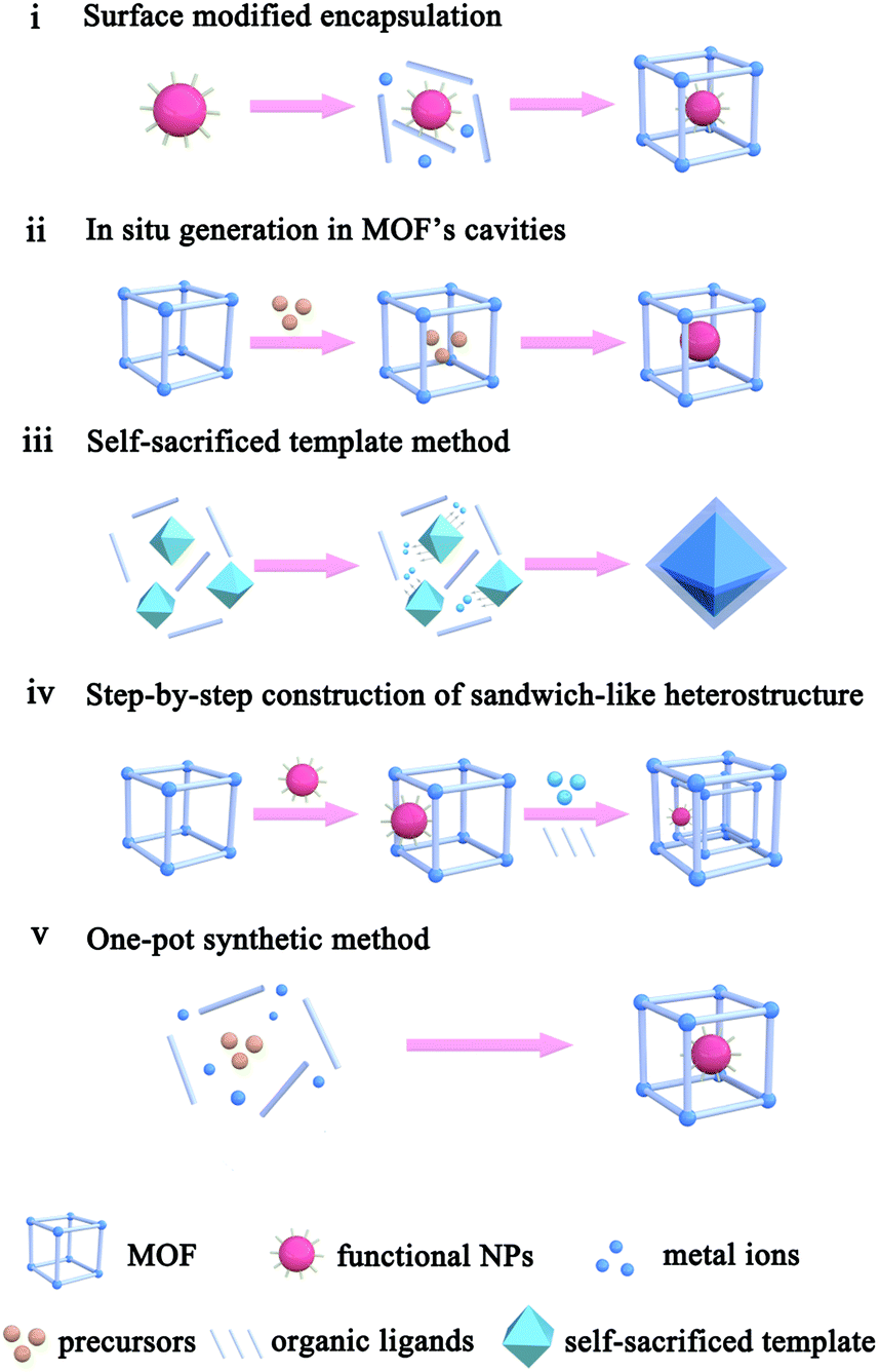 | ||
| Scheme 1 Main approaches used for the construction of MOF-based composites. | ||
2.1. Surface modified encapsulation
The encapsulation method, also called “build-bottle-around-ship”, is based on two main steps: (i) NPs with uniform size, structure and morphology are prepared; (ii) MOF shells are grown on presynthesized NPs. Generally, great lattice structure barriers between MOFs and encapsulated materials often exist, leading to self-nucleation of MOFs instead of forming the encapsulation structure. To overcome such barriers, structure-flexible materials have been used bridges to connect MOFs with encapsulated materials. For instance, Huo et al. and Tsung et al. subsequently modified NPs with surfactants PVP and CTAB to compensate the lattice mismatch at NP@MOF interfaces (Fig. 1).40–42 Using such organic surfactants, MOFs could easily nucleate on the NP surface. Besides surfactants, some metal oxides or hydroxides could be employed to modify NPs and grow MOFs.43–45 Using encapsulation, NPs with various morphologies and sizes can be encapsulated within MOF shells. Apart from NPs, some other functional materials, including carbon materials, molecular catalysts, enzymes and so on, as well can be embedded in MOF cavities via this method.30,46,47 Unfortunately, the activity of embedded NPs reduced to some extent due to the presence of surface capping agents or metal oxide layers. Furthermore, the complicated interfacial structures make it challenging to study the structural–functional relationship in these composite materials.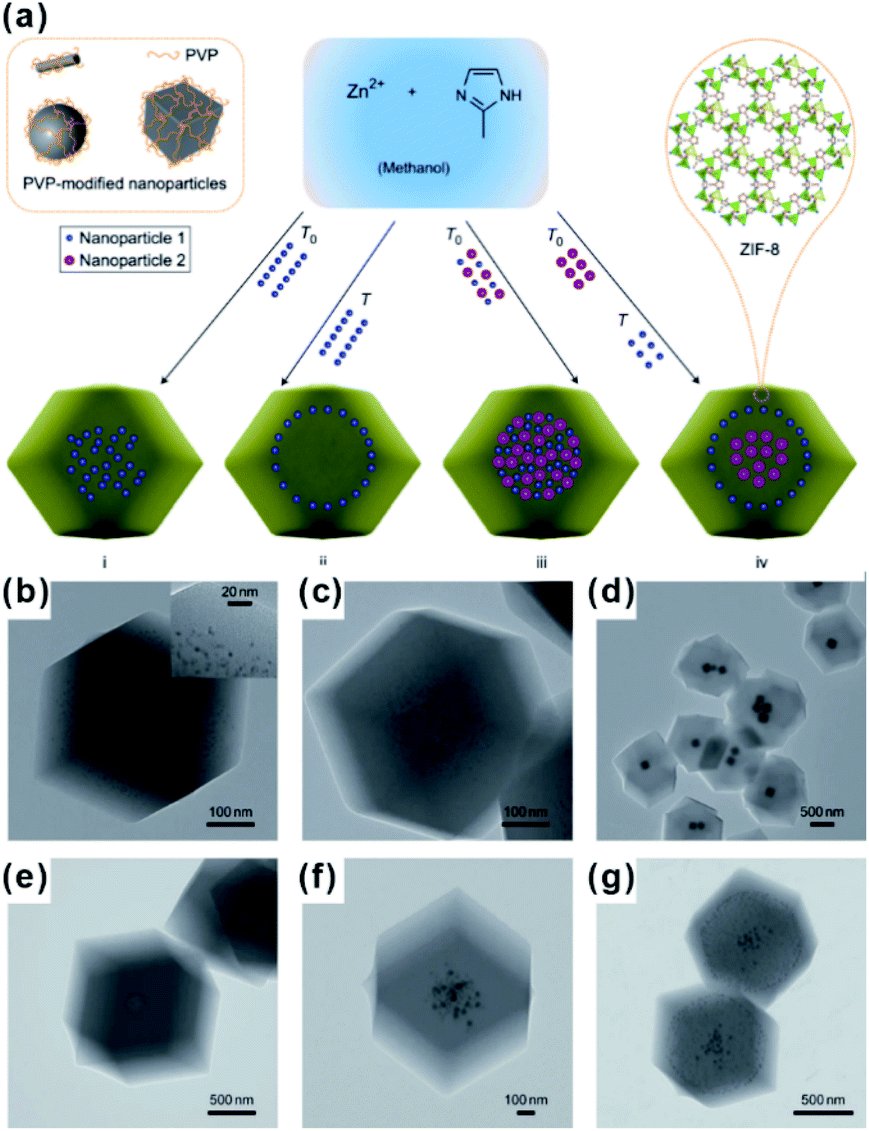 | ||
| Fig. 1 (a) Scheme of controlled encapsulation of NPs in ZIF-8 crystals. Transmission electron microscopy (TEM) images of hybrid crystals containing: (b) 3.4% 3.3 nm Pt NPs, (c) 0.7% 3.3 nm Pt NPs, (d) Ag cubes, (e) 13 nm Au NPs, (f) 13 nm Au and 34 nm Au NPs in the central area, and (g) subsequent 34 nm Au nanoparticle-rich cores and 13 nm Au nanoparticle-rich transition layers. Reproduced with permission.40 Copyright©2012 Nature Publishing Group. | ||
2.2. In situ generation in MOF cavities
The “ship-in-a-bottle” is another common approach to construct MOF-based composites. Using this method, MOFs are first synthesized. Precursors of the embedded material are then introduced into MOF cavities by diffusion or other ways followed by in situ transformations of desired materials in the MOF cavities via chemical reduction, photoreduction or thermolysis, among others.48–51 The challenge of this synthetic route is to restrict the formation of embedded materials inside the MOF matrix and not on their surfaces. Xu et al. developed a double-solvent method to solve this problem, in which all precursors were made to diffuse into MOF cavities.48 MIL-101 is selected as a favorable host material to construct a NP-embedded structure due to its high stability, elevated pore volume, and two large hydrophilic cavities. To this end, MIL-101 was first dispersed in a hydrophobic solvent (hexane). Precursors dissolved in the hydrophilic solvent (water) were then added to n-hexane. The hydrophilicity of MOF cavities led to adsorption of the precursors dissolved in water in the cavities to further in situ transform into desired materials (Fig. 2a). Note that this double-solvent strategy is not only applied to the in situ generation of monometallic NPs in MOF cavities, but also to bimetallic alloys and core–shell structures (Fig. 2b).52–54 Apart from the double-solvent approach, precursors can controllably diffuse into the MOF cavities by other methods, such as solution impregnation, chemical vapor deposition, and solid grinding.55,56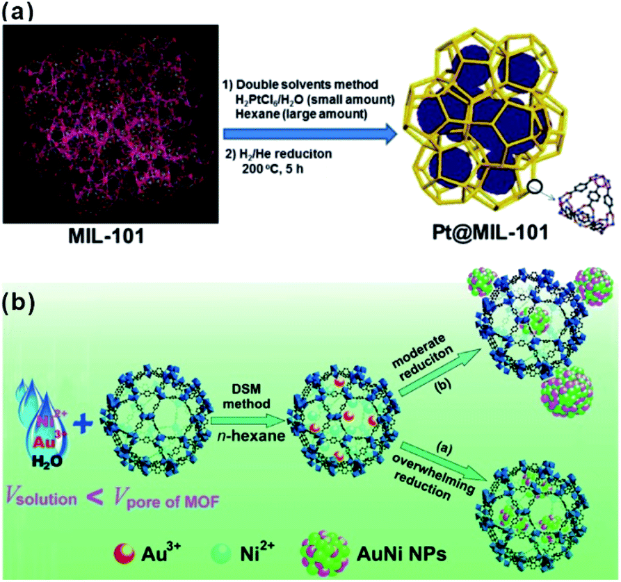 | ||
| Fig. 2 (a) Schematic representation of the synthesis of Pt NPs inside the MIL-101 matrix using the double-solvent method.48 Copyright©2012 American Chemistry Society. (b) Scheme representing the immobilization of AuNi NPs by the MIL-101 matrix using the double-solvent method combined with liquid-phase concentration-controlled reduction (CCR) strategy.52 Copyright©2013 American Chemistry Society. | ||
Without modification with organic surfactants, such as CTAB and PVP, NPs embedded by the in situ generation method have shown clean surface topographies. In addition, NPs restricted by MOF cavities looked very small and uniform in size, beneficial for practical applications. Strikingly, NPs with some special structures and compositions can readily be produced by an in situ reaction in MOF cavities acting as nanoreactors under mild conditions. For instance, Zhou et al. fabricated uniform truncated octahedral face-centered-cubic (fcc) ruthenium (Ru) NPs with exposed {111} and {100} planes, which is often difficult to form by traditional approaches, using a truncated octahedral inner cavity (diameter 2.5 nm) of a porous coordination cage (PCC-2) as the nanoreactor.57 The obtained unique structure of Ru NPs yielded high catalytic activities towards methanolysis of ammonia borane (Fig. 3). Furthermore, the authors successfully constructed super reactive cobalt nanoclusters in highly negatively charged porous coordination cages (PCC-2a) via in situ reduction.58 Chen and Zhou et al. applied ZIF-8 cavities as a confined template to form sub-2 nm atomically ordered intermetallic PdZn NPs by a co-reduction method.59–61
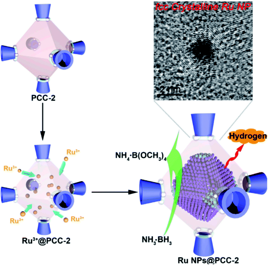 | ||
| Fig. 3 Scheme representing the synthesis of fcc Ru NPs via PCC-2 as the template. Reproduced with permission.57 Copyright©2018 Elsevier Inc. | ||
Nevertheless, in situ generation still suffers from some problems. Firstly, the formation process of embedded materials may destroy the internal structures of MOF templates to some extent. In addition, the morphology, surface structure and density of embedded materials cannot well be controlled, thereby not conducive to understanding the structure–performance relationship of MOF-based composites.
2.3. Self-sacrificed template method
For MOF-based composites, it is very important to control the encapsulation status of embedded materials within the MOF matrix finely, which will significantly affect the practical performances, especially in catalysis and sensing. Although many construction methods of well-defined NP@MOF composites have been attempted, finding generalized routes is quite challenging. The nature of solid reaction and relatively slow kinetics makes the self-sacrificed template strategy effective for the fabrication of core–shell or hollow nanostructures.26,62–64 The key to the successful fabrication of NPs@MOF composites by using a self-sacrificed template is to find appropriate template materials and reaction conditions, in which the release rate of metal ions from the template must match the coordination rate with organic linkers to guarantee the formation of the MOF shell on the self-sacrificed template surface instead of solution. Our group was the first to apply the self-sacrificed template method to fabricate metal oxide semiconductor@MOF composites, where ZnO nanorods did not only act as template but as a Zn source for the formation of ZIF shells (Fig. 4a–c).26,65 The self-sacrificed template method is simple and universal, where both metal oxides and alloys containing transition metals can be utilized as template materials.66–68 For example, Wu and Li et al. employed PtNi alloy NPs as template to successfully fabricate PtNi@MOF-74 composites via a coordination-assisted oxidative etching process (Fig. 4d).62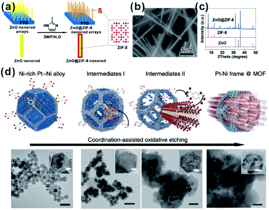 | ||
| Fig. 4 (a) Scheme of ZnO@ZIF-8 nanorods synthesized by the self-template strategy. (b) SEM image and (c) XRD pattern of ZnO@ZIF-8 nanorods. Reproduced with permission.26 Copyright©2013 American Chemistry Society. (d) Scheme and corresponding TEM images of the coordination-assisted oxidative etching process (scale bars represent 50 nm). Insets are magnified TEM images (scale bars represent 5 nm). Reproduced with permission.62 Copyright©2015 Nature Publishing Group. | ||
Compared to other approaches, the self-sacrificed template route suffers from some limitations when it comes to template selection, but it provides a possible route to finely control the structure, thickness and morphology of MOF shells. For example, in the nanoflower-like RhNi@MOF-74(Ni) synthesis, our group successfully controlled the thickness of the MOF shell by tuning the Ni content in the self-sacrificed RhNi alloy template.66 Furthermore, we used 2-methylimidazole or 2,5-dihydroxyterephthalic acid as etching agents to selectively dissolve Ni or Co elements of RhCoNi ternary alloy NCs to respectively form MOF-74(Ni) and ZIF-67(Co) shells on the alloy surface.67 Due to great differences between the two obtained MOF shells in terms of aperture/cavity size, the as-prepared composites looked promising as versatile platforms to systematically study the relationship between performance of composites and structure of MOF shells. Moreover, multi-component MOF shells can be realized by introducing another metal source during the formation of MOFs.69
Apart from constructing MOF-based composite nanoparticles, the self-sacrificed template method was also applied to fabricate some MOF film-based devices in sensor or catalysis applications.70–72 For example, the ZnO@ZIF-CoZn gas senor was prepared by coating a layer of ZIF-CoZn thin film on a ZnO nanowire array via a self-sacrificed template method. In addition to the dissolved Zn2+ from the ZnO nanorod, foreign Co2+ was also involved in the synthesis of ZnO@ZIF-CoZn, leading to the formation of the dual metal MOF thin film on the ZnO nanowire array (Fig. 5).73
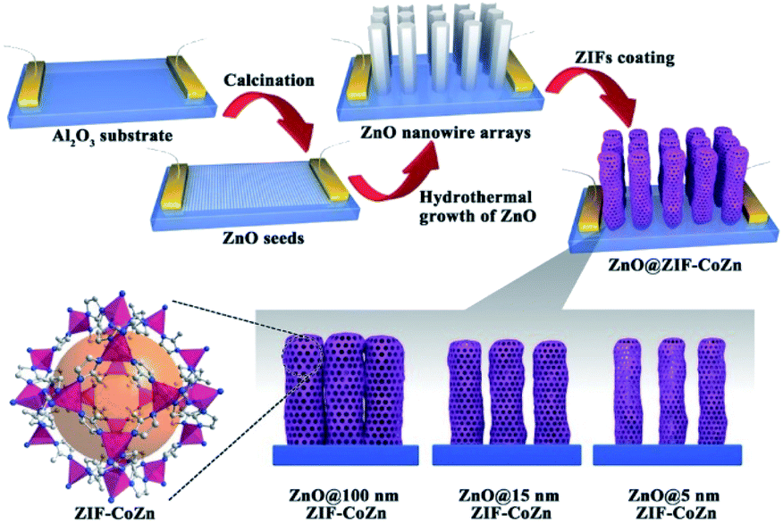 | ||
| Fig. 5 Schematic illustration of the preparation of ZnO@ZIF-CoZn gas sensors Reproduced with permission.73 Copyright©2016 WILEY-VCH Verlag GmbH & Co. KGaA. | ||
Thus, excellent controllability of the self-sacrificed template method provides more space to achieve different structured MOFs on the NP catalyst surface, facilitating in-depth exploration of the structural–functional relationship in MOF-based composites.
2.4. Step-by-step construction of the sandwich-like heterostructure
As mentioned above, restricting the formation of functional materials inside or outside MOF matrices is often challenging. The random distribution of functional NPs in the MOF matrix does not only lead to poor practical repeatability of MOF-based composites but also greatly affect the analysis of the relationship between real structure–function. To solve this problem, Tang et al. fabricated MOF-supported metal catalysts by growing additional MOF layers on the catalysts to form a sandwich-like structure.23,74,75 They first synthesized MIL-101 loaded with Pt NPs and then epitaxially grew another MIL-101 shell with a different thickness outside the as-prepared Pt@MIL-101 particles.23 As a result, all Pt NPs were embedded in the very thin MIL-101 layer, which did not affect the diffusion of substances (Fig. 6). The resulting MIL-101@Pt@MIL-101 sandwich-like catalysts exhibited high selectivity towards the hydrogenation of the C![[double bond, length as m-dash]](https://www.rsc.org/images/entities/char_e001.gif) O functional groups of α,β-unsaturated aldehydes. Note that thickness of the outer MOF shell in sandwich-like heterostructures plays a crucial role in the overall catalytic performance. Thick shells will restrict the diffusions of reactants and products, thereby reducing the reaction conversion significantly although selectivity should be improved to the same extent.75
O functional groups of α,β-unsaturated aldehydes. Note that thickness of the outer MOF shell in sandwich-like heterostructures plays a crucial role in the overall catalytic performance. Thick shells will restrict the diffusions of reactants and products, thereby reducing the reaction conversion significantly although selectivity should be improved to the same extent.75
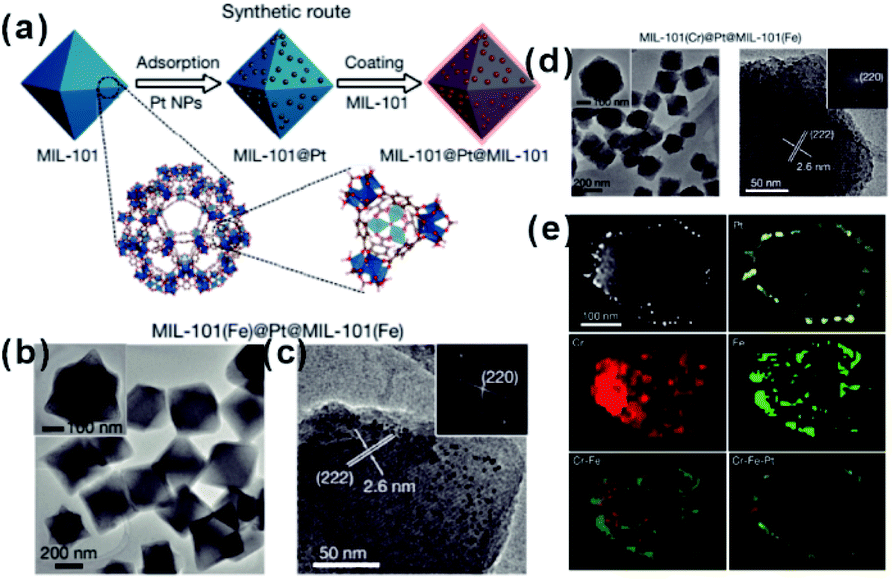 | ||
| Fig. 6 (a) Synthetic route of sandwiched MIL-101@Pt@MIL-101 composites. (b and c) TEM images of the as-prepared MIL-101(Fe)@Pt@MIL-101(Fe). (d) TEM images of the as-prepared MIL-101(Cr)@Pt@MIL-101(Fe) and (e) corresponding HAADF-STEM image and elemental mapping images. Reproduced with permission.23 Copyright©2016 Nature Publishing Group. | ||
2.5. One-pot synthetic method
Each of the above-mentioned methods involves multiple steps. In fact, a few examples demonstrated that MOF-based composites can directly be produced in one step. For example, Liu and Tang et al. synthesized Au@MOF-5 by directly mixing Au precursors with MOF-5 precursors.76 Using one-pot synthesis, the Au precursor was first reduced to Au NPs by dimethyl formamide (DMF), and then MOF-5 spontaneously grew freshly formed Au NP surfaces to yield core–shell structures. One-pot synthesis relies on rationally manipulating the reduction rate of metal ions and/or growth rate of MOFs. Accordingly, Luque and Li et al. succeeded to control the encapsulation of “clean” Pt clusters within UIO-66 by a novel kinetically modulated one-step strategy with the assistance of a H2 reducing agent (Fig. 7).77,78 The success of their method was closely related to that using a DMF solvent. For the formation of Pt/UiO-66 composites, DMF and its trace oxidization product (Me2NCOOH) would act as a “bridge” for connecting MOF precursors to as-reduced Pt clusters, thereby inducing the anisotropic growth of MOFs around the Pt surface. However, unfortunately, one-pot synthesis is not a universal strategy despite being very simple and efficient.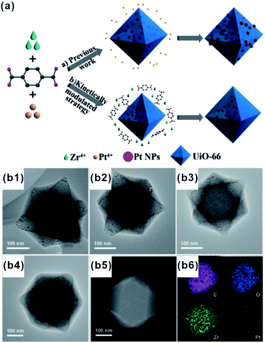 | ||
| Fig. 7 (a) Incorporation of Pt NPs in MOFs through an in situ one-step strategy and a kinetically modulated in situ one-step strategy. (b1–b4) TEM images of Pt@UiO-66 nanocomposites prepared by different volume ratios of H2/air. A (b5 and b6) HAADF-STEM image and corresponding elemental mapping of Pt@UiO-66. Reproduced with permission.77 Copyright©2016 WILEY-VCH Verlag GmbH & Co. KGaA. | ||
3. Functions of MOFs in application of MOF-based composites
To gain a better understanding of performance enhancement of MOF-based composites in practical applications such as catalysis, sensors, adsorption and separation, the roles played by MOF components should be clarified. Thus, the actual functions of MOF components are discussed through specific reported examples.3.1. MOFs as armors to protect embedded catalysts
In the catalytic process, the size effect of catalysts has been extensively investigated. With the decrease of particles in size, more active sites will be exposed, resulting in significantly enhanced activity using ultra-small NPs compared with larger NPs.79–81 However, under real reaction conditions, NPs always prefer to agglomerate to reduce their surface energy, inevitably leading to declined catalytic efficiency. For encapsulation of nanocatalysts within the MOF, the MOF shell may act as an armor to protect the encapsulated NPs from agglomeration. Meanwhile, owing to the adjustable porous structure, the reaction substrates could still diffuse through the MOF shell to active sites. Li and Jiang et al. developed a highly efficient heterogeneous MOF-supported Pd catalyst for water-mediated Suzuki–Miyaura and Ullmann coupling reactions.49 The clean surface and ultra-small size of Pd NPs yielded catalysts with high catalytic efficiency towards all substrates, including aryl chlorides, very stable reactants. Strikingly, the MOF shell armoring around Pd NPs led to stable catalysts with negligible metal loss and activity decrease after many cycles. Xu and co-workers successfully immobilized ultrafine Pt NPs into MIL-101 pores by the double-solvent method.48 The MOF shell armoring around Pt NPs resulted in composites with high activity and stability towards liquid-phase ammonia borane hydrolysis, solid-phase ammonia borane thermal dehydrogenation, and gas-phase CO oxidation. In addition to ultra-small NPs, sub-nanometer clusters might also be immobilized through fabrication of the MOF armor outside to improve stability under reaction conditions.82–85 Pardo and co-workers chemically synthesized sub-nanometer Pt02 clusters within thioether-functionalized MOF channels to overcome problems linked to synthesis and stabilization.84 The obtained Pt02-MOF materials efficiently catalyzed a series of hydrogenation reactions, including NH4CN synthesis at room temperature, CO2 hydrogenation at a low temperature (<140 °C), and alkene hydrogenation at 60 °C. Besides, their strategy can be employed to stabilize relatively unstable functional materials. For instance, cuprous oxide (Cu2O) is an abundant and environmentally friendly catalyst in many application fields. However, the poor stability limited its further application, especially in solution. Hence, Ma and Cheng integrated Cu2O NPs into ZIF-8 via a template protection–sacrifice (TPS) method.86 The resulting yolk–shell structure showed excellent catalytic efficiency towards 4-nitrophenol hydrogenation. After five cycles, the conversion rate after a 20 min reaction still reached 98%, suggesting that the MOF (ZIF-8) shell effectively protected Cu2O cores from inactivation during catalysis and promoted the recycling stability (Fig. 8).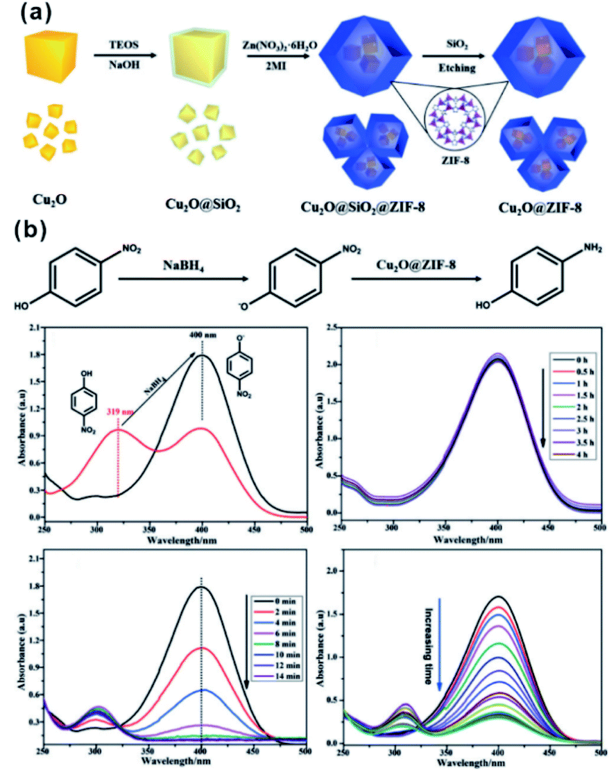 | ||
| Fig. 8 (a) Schematic illustration of synthesis of the Cu2O@ZIF-8 composite, and (b) catalytic reduction equation of 4-nitrophenol to 4-aminophenol using Cu2O@ZIF-8. Reproduced with permission.86 Copyright©2018 WILEY-VCH Verlag GmbH & Co. KGaA. | ||
As natural nanocatalysts, enzymes have long attracted scientists' intense attention because of their excellent selectivity, specificity, and activity. However, enzymes suffer from poor stability and reproducibility, as well as high sensitivity to environmental changes, such as temperature, pH, and presence of toxic chemicals. These factors hinder enzyme usage, especially in industrial applications. Using MOFs as armors provides a promising method to improve the stability and anti-interference ability of enzymes while maintaining their high reactivities.87–89 Tsung et al. employed a de novo approach to embed catalase into ZIF-90.28,29 The resulting MOF-shell did not only prevent catalase leaching but also provided size-selective shelter that increases the enzyme tolerance against protease with a bigger size than that of catalase. In addition, the stability of immobilized enzymes in MOF shells was much higher than that of free enzymes under denaturation media, such as organic solvents and extreme temperature/pH. Further studies have shown that an increase in stability against solvent and thermal conditions has been attributed to confinement of enzymes within MOFs. This, in turn, declines conformation changes of enzymes and enhances their structural rigidity. For example, examination of stabilities of CAT@ZIF-90 and free CAT under urea and a denaturing reagent and at a high temperature (80 °C) showed that exposure to 0.05 M urea decreased the activity of free CAT to 3.5% while that of CAT@ZIF-90 reduced to only 85.5%. Surprisingly, CAT@ZIF-90 still maintained high activity at a urea concentration of 6 M. The structural conformation of embedded CAT has been further studied by fluorescence spectroscopy and the results were consistent with the above experiments (Fig. 9). Zhou and co-workers tested the catalytic efficiency and recyclability of horseradish peroxidase, cytochrome c and microperoxidase-11 encapsulated in PCN-333(Al, Fe) under harsh conditions. The results showed that the catalytic activities of encapsulated enzymes remained almost unchanged after several cycles.90
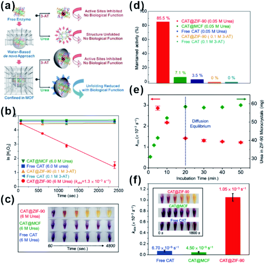 | ||
| Fig. 9 (a) De novo approach and structural confinement of CAT@ZIF-90. (b and c) Kinetic measurements of H2O2 degradation of free CAT, CAT@MCF, and CAT@ZIF-90 incubated with urea and 3-AT. All assays are performed in Tris buffer (pH 7.5, 50 mM). (d) Maintained activity of free CAT, CAT@MCF and CAT@ZIF-90 incubated in 0.05 M urea, and CAT@ZIF-90 incubated in 0.1 M 3-AT. (e) Amounts of urea diffused into ZIF-90 microcrystals (green) and kobs of CAT@ZIF-90 (red) after incubation in 6 M urea for various periods of time. (f) Apparent rate constants after treatment at 80 °C for 3 min (inset shows photographs of time-dependent FOX assay). Reproduced with permission.29 Copyright©2017 American Chemistry Society. | ||
In fact, employing MOFs to protect the embedded materials has been applied for encapsulation of some molecular catalysts. For example, a ruthenium complex molecule catalyst, (tBuPNP)Ru(CO)–HCl (tBuPNP = 2,6-bis((di-tert-butylphosphino)methyl)pyridine) was successfully embedded in UIO-66 (namely Ru@UIO-66) via an aperture-opening process.47 Compared to an analogous homogeneous catalyst, the heterogeneous Ru@UIO-66 catalyst can not only maintain high catalytic activity of CO2 hydrogenation to formic acid but can also be recycled five times without structural decomposition or catalyst poisoning. These features have been attributed to protective aspects of the MOF shell.
3.2. MOFs as filter membranes to screen substrates
MOFs possess uniform and adjustable pore structures, and thereby are widely used as filter membranes for gas separation due to the channel screening effect.91 Such functions are also utilized in practical applications of MOF-based composites in sensors or selective catalysis.In the sensor field, sensing materials with MOFs as shells are usually used as artificial mimetic enzymes to detect specific molecules. During the sensing process, MOFs often act as filter membranes to allow specific molecules to access the surface of embedded sensing materials to generate signals while blocking other incomparable interfering substrates. We previously employed ZnO nanorod arrays as self-sacrificed templates to form ZnO@ZIF-8 core–shell nanorod arrays.26 Note that ZnO is commonly employed as a semiconductor material in photoelectrochemical (PEC) detection. However, ZnO can respond to all hole scavengers during PEC detection due to its high sensitivity, limiting its application in the detection of specific molecules. In ZnO@ZIF-8 core–shell nanorod arrays, ZIF-8 shell plays the role of a molecular size filter to allow smaller sized molecules (H2O2) than ZIF-8 (aperture size of 3.4 Å) to pass through the MOF shell and be captured by photogenerated holes on a ZnO surface to produce an enhanced PEC signal. By contrast, bigger size molecules (AA) did not have a similar effect and they could block MOF channels, leading to declined PEC signals (Fig. 10a–c). Furthermore, we constructed a series of ZnO@ZIF nanorod arrays with different MOF shells (ZnO@ZIF-7 and ZnO@ZIF-71).65 According to PEC detection results, the flexibility of the MOF structure can easily be judged by the PEC response of the sensor towards different sized molecules (Fig. 10d). Moreover, this effect of the MOF shell may also be applied in fluorescence, electrochemical, gas or Raman sensors.73,92–94
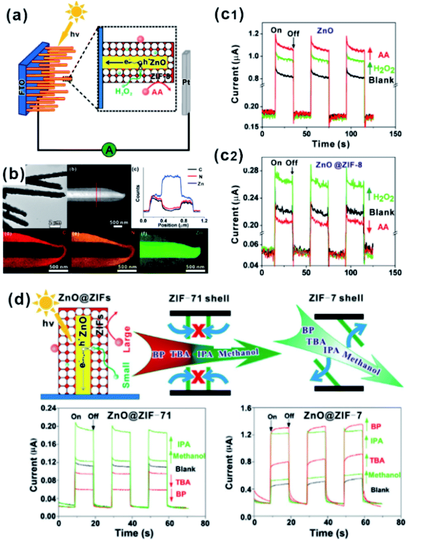 | ||
| Fig. 10 (a) Schematic illustration of the PEC sensor with good selectivity towards H2O2. (b) Low-magnification TEM image, HAADF-STEM image, cross-sectional compositional line profiles and elemental maps of ZnO@ZIF-8 nanorods. (c1 and c2) Photocurrent response of ZnO and ZnO@ZIF-8 nanorod arrays. Reproduced with permission.26 Copyright©2013 American Chemistry Society. (d) Schematic illustration of the ZnO@ZIF based PEC sensor (ZnO@ZIF-7 vs. ZnO@ZIF-71) with molecular size selectivity. Reproduced with permission.60 Copyright©2016 The Royal Society of Chemistry. | ||
The size screening effect of MOFs has well been demonstrated in some size-dependent catalytic systems. Molecules with the same functional groups but different molecule sizes are often employed to test this effect. In the hydrogenation reaction, Jiang's group perfectly demonstrated the enhancement of size-selectivity depending on the size of MOF pores by using different sized olefins. They successfully prepared Pd nanocube@ZIF-8 catalysts with a well-defined porous structure and uniform pore size MOF shell acting as molecular sieves to screen molecules of different sizes.27,44 For example, 1-hexene with a molecular size of ca. 2.5 Å passed well through the ZIF-8 shell and was totally hydrogenated within 90 min. By contrast, the Pd nanocube@ZIF-8 catalyst exhibited negligible activity towards cyclooctene with a molecular size of 5.5 Å as it is larger than ZIF-8 pores (Fig. 11). Straight-chain molecules and corresponding aromatic molecules with the same functional groups have also been used as comparative groups to confirm the role of MOFs as a filter membrane. For instance, Wang and Su et al. utilized a silica mediated sacrificial template strategy to synthesize yolk–shell structured Au@ZIF-8 nanoreactors.95 The as-obtained ZIF-8 shell acted as size-selective filter allowing the passage of smaller sized reactants (1-butanol and 1-hexanol) arriving at Au NPs while blocking 3-phenylpropanol containing benzene groups larger than the ZIF-8 aperture. The as-prepared Au@ZIF-8 nanoreactors delivered excellent size selectivity during catalytic oxidation of alcohols with different molecular sizes. This size selectivity presented in MOF-based composites in turn confirmed completely embedding of the catalysts in the MOF shell instead of its surface.39,45,96,97
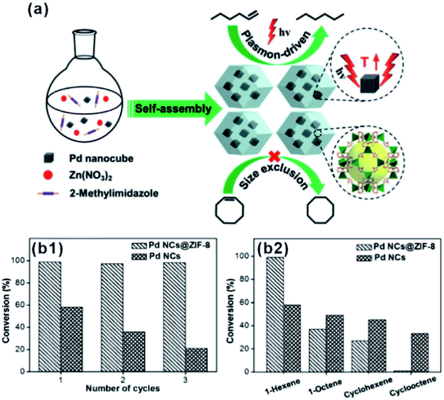 | ||
| Fig. 11 (a) Self-assembly of Pd nanocube@ZIF-8 and plasmon-driven selective hydrogenation catalysis of olefins. (b1 and b2) Selective catalytic performance of the Pd nanocube@ZIF-8 catalyst. Reproduced with permission.27 Copyright©2016 WILEY-VCH Verlag GmbH & Co. KGaA. | ||
Besides the size selection effect, other factors, such as specific interaction with certain molecules and hydrophobicity of MOF pores, also play important roles in the application of MOF based composites.98 For example, Xu’s group successfully fabricated van der Waals heterostructured Cu-TCPP-on-Cu-HHTP thin films on the sensor device, in which the Cu-TCPP top layer can selectively suppress the penetration of NH3 due to strong interactions with polar gas molecules. Benefiting from the novel structure, a molecular sieving Cu-TCPP layer on a chemiresistive sensing Cu-HHTP layer, the as-prepared device realized the highest response to benzene of all reported room temperature chemiresistive sensing materials and reversed the selectivity of Cu-HHTP toward benzene and the strongly interfering molecule, NH3.99
3.3. MOFs as steric modulators to control the over adsorption state of reaction substrates
In addition to filters to screen out molecules with different sizes, MOF shells grown on NPs could act on selectivity by controlling the adsorption state of reaction substrates on the catalyst surface. To obtain target products, previous studies focused on controlling the adsorption state of reactants by adsorbing large steric molecules or constructing porous shells on active site surfaces.100,101 Compared to traditional porous materials and simple molecular adsorption, MOF shells may provide adjustable space to construct suitable cavities to control the adsorption state of reaction substrates.For selective hydrogenation reactions over MOF-based composite catalysts, cinnamaldehyde (CAL) is often used as a model molecule. CAL molecules containing α,β-unsaturated aldehydes with two hydrogenated sites are usually hydrogenated on “CO” and “CC” bonds simultaneously due to their flat adsorption on the NP surface using traditional catalytic processes (Fig. 12a).102–104 After modification of NPs with the MOF shell, CAL molecules would prefer to adsorb vertically on the NP surface containing aldehyde groups (“CO”) due to the confinement effect of MOF channels. Hence, CAL molecules are favorable for the selective hydrogenation to cinnamic alcohol instead of other products. This effect is also manifested in the selective synthesis of other α,β-unsaturated aldehydes and alkanes in the presence of MOF-based heterostructure catalysts.69,105–108 It is worth noting that the inherent structure of MOFs, including cavity size and structural flexibility, would also influence the catalytic effect caused by the special adsorption state of reactants in MOF channels. For example, Huo et al. encapsulated Pt NPs within MOFs (ZIF-8 and UIO-66) containing different pore sizes. Their data showed that a suitable size of the MOF channel can effectively prevent the rotation of molecules, improving the catalytic selectivity.109 On the other hand, we used flexible ZIF-8 and rigid ZIF-71 to encapsulate Pt NPs and studied the influence of MOF structure flexibility on the catalytic selectivity. Compared to flexible ZIF-8, rigid ZIF-71 as a shell may significantly improve the selectivity (Fig. 12b and c).75
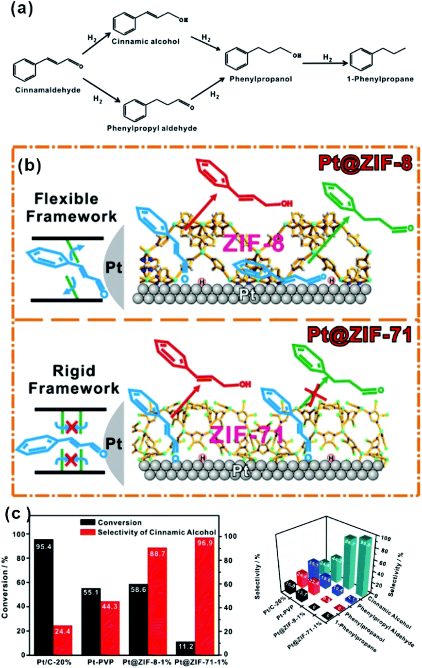 | ||
| Fig. 12 (a) Reaction paths of CAL hydrogenation. (b) Schematic illustration of hydrogenation of CAL on Pt NPs embedded within flexible ZIF-8 and rigid ZIF-71, respectively. (c) Conversions and selectivity of four products of CAL hydrogenation over Pt/C-20%, Pt-PVP, Pt@ZIF-8-1%, and Pt@ZIF-71-1%. Reproduced with permission.75 Copyright©2017 WILEY-VCH Verlag GmbH & Co. KGaA. | ||
In addition to star model molecule CAL, such composite catalysts have also been extensively applied in other selective catalytic processes.62,110–112 For semi-hydrogenation of alkynes, Li and co-workers used a Pd embedded hollow Zn/Co-ZIF (Pd@H-Zn/Co-ZIF) as a catalyst for acetylene hydrogenation. Unlike naked Pd NPs, acetylene could be hydrogenated over a Pd@MOF hybrid catalyst to form ethylene instead of ethane in the presence of MOF shell.113,114 In addition, flower-like RhNi@MOF-74 catalysts for hydrogenation of diphenylacetylene have been successfully prepared, in which Rh–Ni alloy nanoflowers were encapsulated within MOF-74(Ni) shells of different thickness.66 Note that the size of the semi-hydrogenated product (cis-diphenylethene) is similar to that of the MOF-74 aperture. Hence, its generation on the RhNi surface would inhibit cis–trans isomerization and further hydrogenation reactions by MOF shells. As a result, diphenylacetylene in the presence of the catalyst can be selectively hydrogenated to the cis-product instead of trans-product that is thermodynamically preferred.
Since Kim and co-workers first used MOFs in asymmetric catalysis, MOF-based materials have been since applied to asymmetric heterogeneous catalysis owing to their confinement effect.115–117 In 2005, Lin’s group designed for the first time a homochiral MOF for asymmetric catalysis by introducing a privileged chiral ligand into the MOF structure to yield a high ee 1,1′-bi-2-naphthol (BINOL) product116,118,119 In addition, Hupp et al. designed a homochiral MOF with another category of chair catalysts (Mn(salen)) for asymmetric epoxidation.120–122 In 2015, Qi et al. synthesized two new polyoxometalate (POM)-based MOFs: ZnW-PYI1 and ZnW-PYI2, respectively.123 This special composite proved to perform as an effective asymmetric catalyst for conversion of carbon dioxide to cyclic-carbonates in presence of L-BCIP (L-N-tert-butoxycarbonyl-2-(imidazole)-1-pyrrolidine) in MOF pores by controlling the orientation of substrate moieties in the reaction medium (Fig. 13).
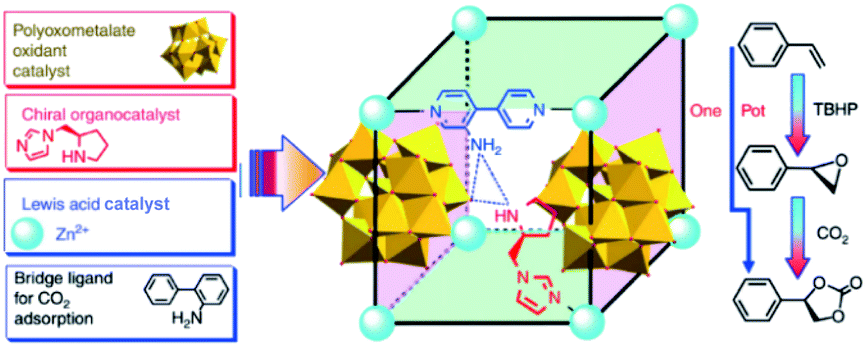 | ||
| Fig. 13 Synthesis of MOF and a tandem catalytic process of asymmetric cyclic carbonate transformation from olefins and carbon dioxide. Reproduced with permission.123 Copyright©2015 Nature Publishing Group. | ||
3.4. MOFs as sponges to enrich reactants
With tunable structure, high surface area and functional group modified organic ligands, MOFs have been intensively investigated as ideal artificial sponge materials for selectively enriching some specific reactants.2,124 As a result, MOF-based composites have been widely applied in catalysis, adsorption separation and sensing, among others.As an excellent hydrogen storage material, some MOFs exhibit specific adsorption to hydrogen, which can be employed to improve the catalytic performance of hydrogenated reactions.125,126 Wu and Li et al. reported a novel Pt–Ni frame@Ni-MOF-74 frame structure prepared by the self-sacrificed template strategy.62 Since the ‘breath shell’ of Ni-MOF-74 could enrich the hydrogen molecules, the as-prepared catalysts showed high reactivity towards the hydrogenation reaction. Strikingly, microporous Ni-MOF-74 grown on a Pt–Ni frame surface can also be used as a molecular sieve with excellent molecular-size selectivity towards different reactants.127 In addition, some MOFs are ideal materials for CO2 absorption due to the presence of abundant Lewis acids. Such properties should improve the catalytic efficiency of MOF-based composites during CO2 reduction processes.128–130 For example, Xiong and co-workers proposed a Cu3(BTC)2@TiO2 core–shell structure for CO2 photocatalytic reduction.131 The synergy between TiO2 microporous shell producing excitons and MOF microporous core capturing gas molecules led to a dramatic enhancement in activity and selectivity of CO2 photocatalytic reduction to CH4 (Fig. 14).132,133
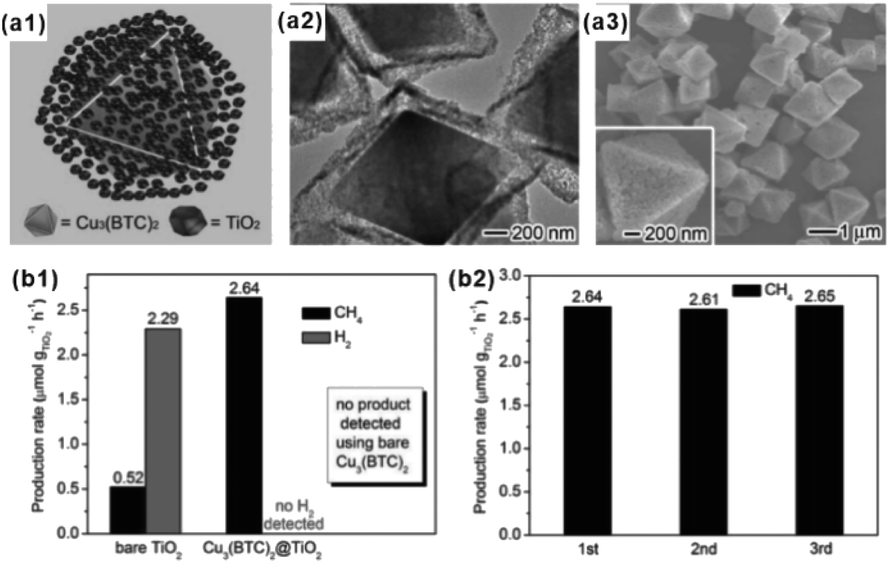 | ||
| Fig. 14 (a1) Structural illustrations: (a2) TEM and (a3) SEM images of synthesized Cu3(BTC)2@TiO2 core–shell structures. (b1) Production yields of CH4 and H2 from CO2 using Cu3(BTC)2@TiO2 core–shell structures and bare TiO2 nanocrystals as photocatalysts. (b2) Recycling tests of the Cu3(BTC)2@TiO2 photocatalyst. Reproduced with permission.131 Copyright©2014 WILEY-VCH Verlag GmbH & Co. KGaA. | ||
Apart from gas-phase reactions, this effect can also be reflected in liquid-phase reactions. For example, core–shell Ag@ZIF-8 nanostructures have been reported for renewable adsorptive separation of low concentrations of butanol from aqueous media under solar light irradiation.134 The selective hydrophobic interaction between butanol and ZIF-8 induced Ag@ZIF-8 composites with high adsorption capacity of low concentration butanol from aqueous solutions. The surface plasmon resonance allowed the Ag core to generate heat under solar light irradiation, leading to butanol release from the ZIF-8 shell (Fig. 15). In addition, the adsorption and separation effect of MOFs has been further confirmed in other environmental fields, such as water purification and dye absorption.135–138 Moreover, after loading some fluorescent molecules, accompanied by the enrichment effect of the MOF structure, these kinds of composite structures are employed in the detection of heavy metal ions and some other molecules as well.139–141
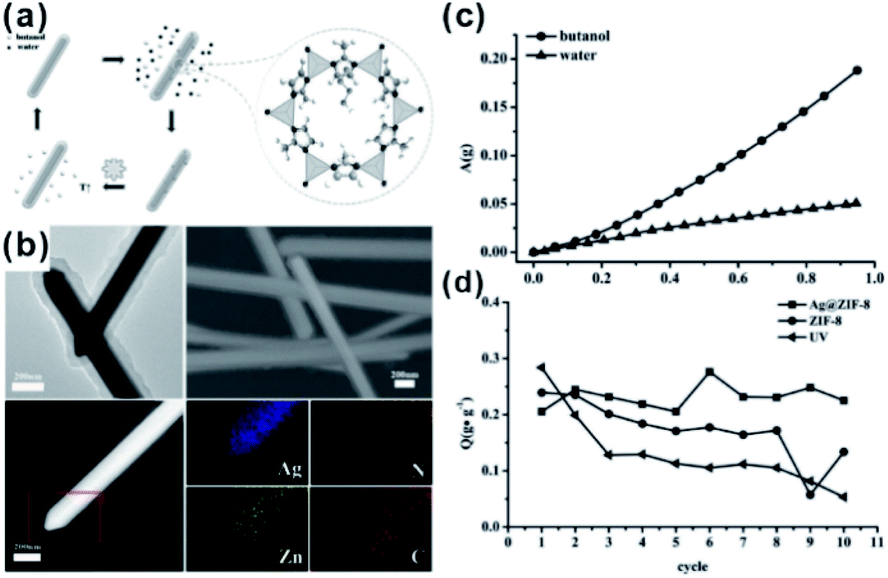 | ||
| Fig. 15 (a) Scheme of a solar-light-driven adsorption/desorption process by core–shell Ag@ZIF-8 nanowires as adsorbents for butanol separation. (b) SEM profiles, TEM images, HAADF-STEM pictures, and EDX elemental mapping of single core–shell Ag@ZIF-8 nanowires. (c) Single-component adsorption isotherms of core–shell Ag@ZIF-8 nanowires toward butanol and water. (d) Comparison of butanol adsorption amount (Q) of different samples after 10 adsorption/desorption cycles. Reproduced with permission.134 Copyright©2015 WILEY-VCH Verlag GmbH & Co. KGaA. | ||
3.5. MOFs as catalysts to provide other active sites
In catalysis, MOFs are promising heterogeneous catalysts due to the presence of unsaturated coordinated metal sites and/or special functional groups of ligands. The active sites are highly dispersed on both the external and internal surfaces of the MOF matrix due to its unique framework structure built with metal nodes and organic linkers. However, metal nodes in the framework of some MOFs are fully coordinated with organic linkers, leading to lack of uncoordinated active sites for reaction. Two common approaches are used to solve this problem. First, special treatment of MOFs (such as heating under vacuum and linker exchange) is required to activate the metal nodes by removing weak-coordinated linkers or solvents (Fig. 16a).142–144 In addition, the apparent morphology of MOF crystals should be regulated elaborately through transformation into two-dimensional nanostructures (e.g., metal–organic monolayer, MOL) to expose more unsaturated coordinated sites (Fig. 16b).145–149 On the other hand, well-designed catalytic sites can be anchored onto the organic linkers of MOFs by introducing specific modification ligands, such as porphyrin, dipyridine, and N,N-dimethylaniline (Fig. 16c and d).150–159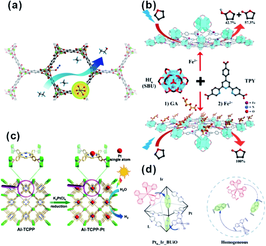 | ||
| Fig. 16 (a) Scheme of ethane oxidation on Fe sites of the MOF. Reproduced with permission.142 Copyright©2014 Nature Publishing Group. (b) Modification of SBUs of FeII-MOLs with gluconic acid for selective oxidation of tetrahydrofuran. Reproduced with permission.149 Copyright©2017 WILEY-VCH Verlag GmbH & Co. KGaA. (c) Scheme showing the synthesis of Al-TCPP-Pt for photocatalytic hydrogen production. Reproduced with permission.153 Copyright©2018 WILEY-VCH Verlag GmbH & Co. KGaA. (d) Scheme representing the operation principle of a self-healing MOF (Ptn_Ir_BUiO) and the corresponding homogeneous system. Reproduced with permission.157 Copyright©2016 American Chemistry Society. | ||
Since highly dispersed active sites are present on MOFs, MOF-based composites with other embedded functional catalysts possess great potentials in tandem reactions. This could better be achieved if synergic catalysis of the MOF matrix and embedded materials is rationally engineered. In most cases, designable functional organic ligands always act as additional Lewis acid or base reactive sites during catalysis. Among these catalysts, amino-modified MOFs have widely been studied, in which –NH2 groups did not only stabilize NPs but also served as active sites in some reactions.160,161 For formic acid dehydrogenation at ambient temperature, the catalyst with amino-functionalized MIL-125 embedding Pd NPs showed higher activity when compared to Pd NPs loaded in pure MIL-125.162 The reason for this has to do with the weakly basic –NH2, which could accept a proton under the reaction conditions to form –+HNH2 and facilitate the dissociation of O–H bonds. Meanwhile, the Pd format intermediately undergoes β-hydride elimination to produce CO2 while leaving the Pd hydride species, subsequently producing H2. The amino group is typically employed in some basic reactions like Knoevenagel condensation due to its weakly alkaline sites. For example, uniform core–shell Pd@IRMOF-3 nanostructures with single Pd nanoparticles surrounded by amino-functionalized IRMOF-3 have been successfully prepared.163,164 The as-obtained composite catalyst showed very high catalytic efficiency in a cascade reaction with 4-nitrobenzaldehyde as the reactant. The Knoevenagel condensation first occurred at the –NH2 group, and the nitro group was subsequently hydrogenated on embedded Pd NPs to produce the final product. Besides the –NH2 group, some acidic groups can as well play the part of second active sites for some tandem reaction by cooperation with embedded functional materials. Our group successfully fabricated highly distributed Pd NPs supported on a sulfonic acid functionalized MOF catalyst, Pd/MIL-101-SO3H, by a simple thermal decomposition. With the cooperation of Pd NPs and –SO3H acidic sites in Pd/MIL-101-SO3H, this catalyst performed outstanding activity in one-pot synthesis of ethyl tetrahydro-2-furoate (ETF) from furoic acid (FA).165
Besides organic linkers alone, some metal-sites anchored on organic linkers might cooperate with embedded species. Lin’s group introduced Pt NPs into stable, porous and phosphorescent metal–organic frameworks built from [Ir(ppy)2(bpy)]+ linkers and Zr based secondary building units by the in situ photoreduction method.166 The as-prepared hybrid catalysts displayed high activity towards photocatalytic hydrogen evolution due to the synergistic photoexcitation of MOFs and electron acceptors of embedded Pt NPs. Coincidentally, Yang and Yaghi et al. anchored ReI(CO)3(BPYDC)Cl (BPYDC = 2,2′-bipyridine-5,5′-dicarboxylate) into zirconium MOFs, UiO-67, (Ren-MOF) near the surface of Ag nanocubes.167 Intensified near-surface electric fields at the Ag nanocube surface led to enhanced CO2-to-CO conversion by about 7-fold under visible light.
The unsaturated coordinated sites of metal nodes could also synergize with embedded materials to facilitate tandem reactions. In general, open metal sites of MOFs serve as Lewis acid sites. Among MOFs, MIL-101 is popular and widely employed as support in cooperative work with embedded materials thanks to its abundant open chromium centers.168,169 A tandem catalyst with Pd NPs supported on MIL-101(Cr) has been prepared to achieve efficient one-step methyl isobutyl ketone (MIBK) synthesis.170 For catalysis, acetone was first converted to mesityl oxide (MO) through high density unsaturated Cr Lewis acid sites. The resulting MO molecule was then further hydrogenated to produce the final product MIBK at Pd active sites. Multi-functional catalysts have also been applied in tandem reactions involving nitroarene reduction and reductive amination of carbonyl compounds.171 In such reactions, nitroarene is first reduced to an aromatic amine on noble metal NPs followed by further reaction with aldehyde or ketone at Cr Lewis acid sites to produce the final secondary arylamine products. For instance, Jiang and Xu et al. encapsulated a PdAg alloy in MIL-101 by cascade reaction.172 Although the doping of Ag slowed down the reaction rate to a certain degree, the selectivity of the target product significantly improved (Fig. 17). Such a construction strategy of synergetic catalysts can also be extended to other MOFs, including UIO-66 with Zr-oxo clusters.173,174 Huang’s group developed bifunctional Zr-MOF based catalysts containing a Pd nanocluster (Pd@UIO-66-NH2) with improved properties reaching 99.9% selectivity and 99% conversion in a one-pot oxidation–acetalization tandem reaction.175 Later, ultrasmall Pt clusters had been introduced into UIO-66-NH2 cavities to fabricate the Pt@UIO-66-NH2 heterostructure. In the one-step synthesis of nitrones, the catalyst exhibited remarkable selectivity and activity due to synergy between selective hydrogenation activity provided by Pt clusters and Lewis acidity/basicity contributed by MOFs.164
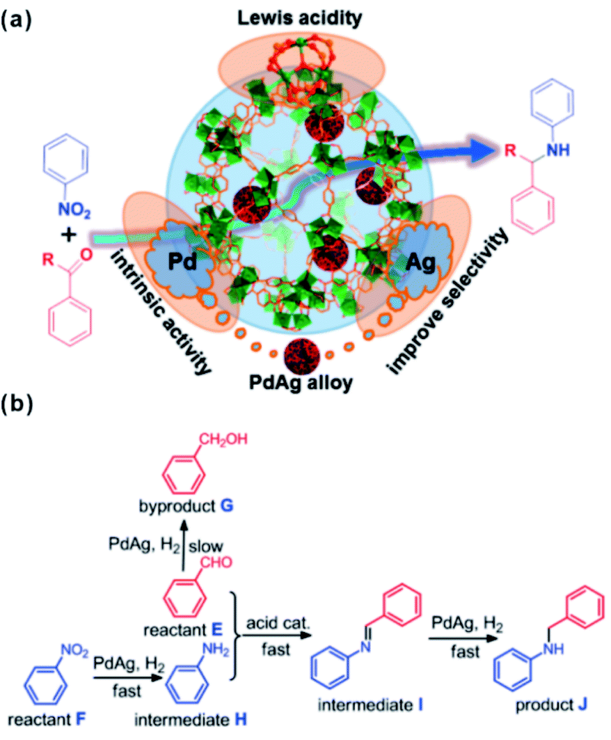 | ||
| Fig. 17 (a) Scheme illustrating the multistep reaction over PdAg@MIL-101. (b) Synthesis of secondary arylamines through hydrogenation of nitrobenzene and reductive amination of benzaldehyde. Reproduced with permission.172 Copyright©2015 American Chemistry Society. | ||
In addition to the function of Lewis acid sites, unsaturated metal-sites of MOFs may influence catalytic performance in other ways.176,177 In 2016, Yaghi and Somorjai et al. showed for the first time the existence of strong interaction between embedded functional species and metal nodes of MOF matrixes.177 Comparison between the activity and selectivity of two MOF-based composite catalysts (Cu NPs dispersed on UIO-66, denoted as Cu-on-UIO-66, and encapsulated within UIO-66, denoted as Cu⊂UIO-66) for CO2 hydrogenation to methanol revealed the performance of Cu⊂UIO-66 to largely exceed that of common Cu/ZnO/Al2O3 catalysts with 8-fold enhanced yield and 100% selectivity towards methanol. The turnover frequency (TOF) of methanol formation was twice that of the Cu-on-UIO-66 catalyst. X-ray photoelectron spectroscopy displayed strong interaction between Cu NPs and Zr oxide secondary building units (SBUs) of MOFs, conducive to enhancement of the catalytic activity. Note that for selective hydrogenation of α,β-unsaturated aldehydes to unsaturated alcohols catalyzed by NP@MOF catalysts, the increase in selectivity was usually attributed to the confinement effect of MOF shells. Later, Tang and co-workers explain the phenomenon according to CAL hydrogenation over sandwich-structured catalyst MIL-101@Pt@MIL-101.23 They found the selectivity of cinnamyl alcohol over MIL-101(Fe)@Pt (86.4%) much higher than that performed over MIL-101(Cr)@Pt (44.0%). Considering the same structure of MIL-101(Fe) and MIL-101(Cr), the increase in product selectivity may be due to interactions between MOF coordinatively unsaturated metal sites (CUBs) and the “CO” bond. From DFT calculations, the adsorption energies of “CO” bonds on Fe3OCl(COO)6H2O and Cr3OCl(COO)6H2O metal nodes were estimated to be −1.26 eV and −1.01 eV, respectively. This led to the different hydrogenation efficiency of “CO” on Fe and Cr metal nodes.95 Recently, Xu and Tsumori et al. successfully prepared a “quasi-MOF” through thermal transformation. The material did not only retain its porous structure but also possessed a large number of unsaturated coordinated nodes, which strengthened the metal-NP/MOF interactions through controlled deligandation of metal/MOF composites.178 In turn, the strengthened interactions between Au NPs and Cr–O nodes of the quasi-MOF dramatically improved the catalytic activity of the prepared Au@quasi-MOF catalyst towards low-temperature CO oxidation (Fig. 18).
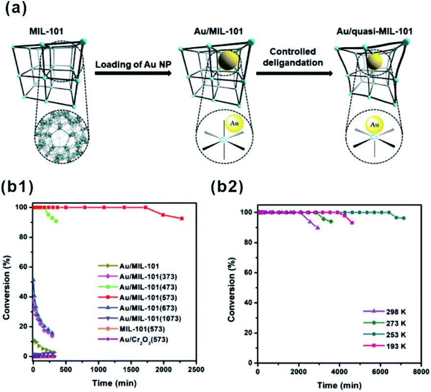 | ||
| Fig. 18 (a) Schematic illustration showing the synthesis of Au/quasi-MIL-101 through controlled deligandation of Au/MIL-101. (b1) Catalytic activity in CO oxidation of different catalysts. (b2) CO oxidation at various temperatures catalyzed by Au/MIL-101(573). Reproduced with permission.178 Copyright©2018 Elsevier Inc. | ||
3.6. MOFs as nano-reactors
In recent decades, nano-reactors with active substances embedded within porous materials to allow specific reaction to take place in limited suitable locations have attracted increasing interest in research and development.179–181 Compared to traditional porous materials, MOFs have more flexible space to immobilize different functional species and create a comfortable micro-environment in the cavity for specific reactions to occur.In 2015, Somorjai and Yaghi et al. incorporated sulfonic acid (–SO3H, S) and ammonium (–NH3+, N), serving as strong acid and weak acid functional groups, into UIO-66 separately or together to regulate the acidity of MOF cavities. After embedding Pt NPs in MOF cavities, all three prepared MOF-based composite catalysts (Pt⊂UIO-66-S, Pt⊂UIO-66-N, and Pt⊂UIO-66-SN) exhibited distinct catalytic performances towards gas-phase conversion of methylcyclopentane (Fig. 19).24 In 2017, the cavity acidity was further regulated by encapsulating considerable amounts of phosphotungstic acid (PTA) in the MIL-101 cavity during the synthetic process of Pt@MIL-101. For hydrogenation isomerization of n-hexane, the prepared MOF composite catalysts with 60% PTA capacity exhibited 100% selectivity towards isoalkanes. Furthermore, mass activity was 9-fold higher than that of traditional aluminosilicate catalysts.25 On the other hand, the activity and selectivity of some reactions are related to the hydrophilicity/hydrophobicity of catalysts, which may also be tuned by modifying the MOF shell. Jiang and co-workers encapsulated Pd NPs in MOF matrixes modified with a hydrophobic polydimethylsiloxane (PDMS) layer to create a hydrophobic micro-environment in MOF cavities. This method greatly enhanced the affinity for hydrophobic substrates.182,183 In addition, Zhang and Huo et al. modified the Pt@UIO-66 catalyst with graphene oxide (GO) to create a hydrophilic environment and promote hydrogenation of hydrophilic substrates, such as 4-nitrophenol.184 Interestingly, the micro-environment of MOF cavities became hydrophobic after the reduction of GO. In turn, this was conducive to reactions with hydrophobic substrates, such as nitrobenzene hydrogenation.185
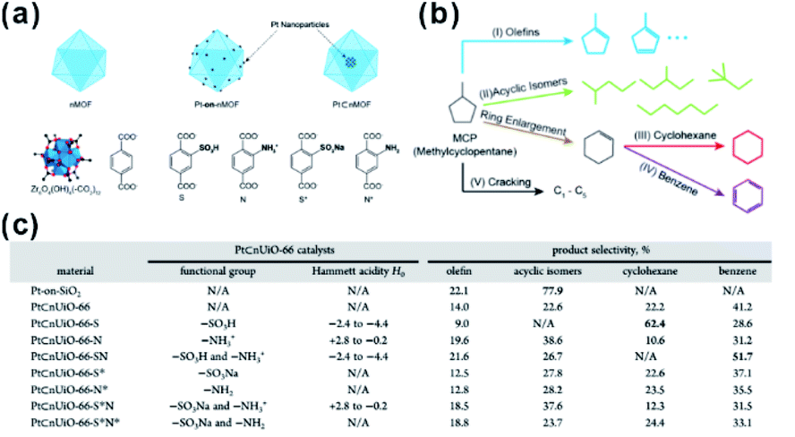 | ||
| Fig. 19 (a) Schematic diagrams of nMOF, Pt-on-nMOF, and Pt⊂nMOF with different functionalized linkers. (b) Scheme showing the reaction diagram of conversion of MCP. (c) Summary of functional groups, Hammett acidity, and product selectivity of Pt⊂nUiO-66 catalysts. Reproduced with permission.24 Copyright©2015 American Chemistry Society. | ||
As nano-reactors, MOFs not only provide a suitable reaction environment but also could integrate different functional catalysts in specific zones by simultaneously constructing multiple active sites in the frameworks or encapsulating different functional active species in the cavities. The diversity of metal ions and functional organic linkers makes MOFs suitable for the design of further multifunctional catalysts for specific reactions. As for MOF-based composites, MOFs always provide second reactive sites to cooperate with guest species as mentioned previously.114,186–194
Compared to designable fabrication of specific multi-site structures, embedding two or more functional materials would help achieve multifunctional catalysts.60,194,195 Zeng and co-workers confined efficient CO2 hydrogenation catalysts, Pt nanocubes and photo-thermal active Au nanocages in a limited space by ZIF-8 encapsulation.196 For hydrogenation of CO2 under light irradiation, MOF shells acted as heat insulators to prevent generated heat by Au nanocages from escaping, generating a localized high-temperature region and improving the reaction conversion.167 On the other hand, MOFs with two or more different functional catalysts in cavities are ideal for cascade reactions that attracted increasing attention owing to a sustainable green process and atom economy efficiency.34 We previously synthesized PtNi@MOF-74-POM catalysts by a facile one-step self-sacrificed template process, in which phosphotungstic acid (POM) was encapsulated during in situ formation of MOF-74 on the surface of branched PtNi NCs.197 The superior hydrogenation activity of the PtNi alloy and esterification activity of the POM yielded PtNi@MOF-74-POM catalysts with superior tandem reaction activity towards one-pot synthesis of amino-ester-type local anesthetic (benzocaine) (Fig. 20).
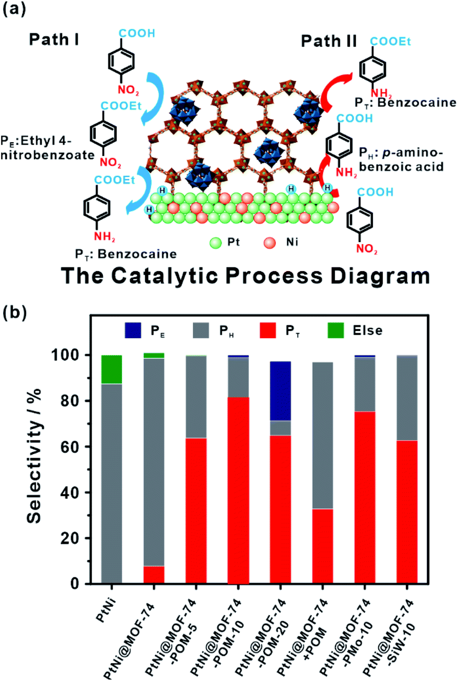 | ||
| Fig. 20 (a) Schematic illustration of tandem catalytic mechanism on PtNi@MOF-74-POM. (b) Catalysis of tandem reaction with different catalysts. Reproduced with permission.189 Copyright©2019 The Royal Society of Chemistry. | ||
Besides traditional inorganic solid catalysts, some enzymes or biocatalytic molecules could also be embedded in MOF cavities to imitate some biocatalytic processes.198,199 Willner et al. imitated the biocatalytic transformation in cells to demonstrate biocatalytic cascades in ZIF-8 cavities by encapsulating two/three enzymes or enzyme/cofactor components.30 Compared to directly dispersed cascade catalysts in solution, high local concentrations of substrates were generated around the enzymes due to the confined environment of MOF cavities, thereby enhancing the efficiency of biocatalytic cascades over enzymes@MOFs. For this reason, the catalytic cascade activity of the two-enzyme system (glucose oxidase and horseradish peroxidase) (Fig. 21a) and three-enzyme system (β-galactosidase, glucose oxidase, and horseradish peroxidase) (Fig. 21b) enhanced by 7.5 and 5.3-fold, respectively. Additionally, NAD+ and NADH operating diffusionally in nature could also enable communication between two enzymes in MOF reactors. Thus, the enzyme@ZIF-8 reactor (alcohol dehydrogenase, NAD+–polymer, and lactate dehydrogenase embedded in ZIF-8) successfully triggered the catalytic reduction of pyruvic acid to lactic acid by ethanol (Fig. 21c and d). Apart from catalysis, MOFs may also be employed for tandem reaction nanoreactors in other fields, such as sensors and drug delivery. Zhang and Dong et al. designed an artificial enzyme system for tandem catalysis using ZIF-8 encapsulated glucose oxidase (GOx) and PdNi NPs.200 The as-prepared GOx@ZIF-8-(NiPd) nanoflowers yielded rapid electrochemical response towards the detection of glucose. In practical applications, glucose is first oxidized to gluconic acid accompanied by generation of H2O2, which then is further oxidized on a NiPd surface to generate electrochemical signals.
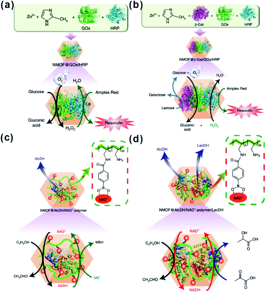 | ||
| Fig. 21 (a) Scheme of the GOx/HRP two-enzyme cascade integrated in ZIF-8 NMOFs. (b) Activation of a three-enzyme biocatalytic cascade encapsulated in ZIF-8 NMOFs. (c) NAD+-mediated biocatalytic cascade of a cofactor-dependent enzyme in ZIF-8 NMOFs. (d) NAD+-mediated two-enzyme biocatalytic cascade in ZIF-8 NMOF nanoreactors. Reproduced with permission.30 Copyright©2018 Nature Publishing Group. | ||
3.7. MOFs as co-catalysts in photocatalysis
Recently, photocatalysis has attracted increasing interest in an effort to solve the energy shortage and environmental problems.201 Some MOFs with semiconductor-like properties are considered as a new kind of photocatalytic material. Compared to traditional inorganic semiconductor materials, the prefect porous crystalline structure of MOFs does not only inhibit the recombination of electron–hole pairs but also facilitate the utilization of charge carriers. Therefore, those MOF materials are promising for photocatalysis, as well as dye degradation, organic transformation, hydrogen production by water splitting, water oxidation, and carbon dioxide reduction.201,202In most photocatalytic processes using MOF-based composites as catalysts, MOFs serve as photosensitizers, absorbing light to generate charge carriers. The photo-excited electrons or holes then transfer to the active sites for further reactions, such as H2-production, O2-production and other organic reactions. Matsuoka et al. first synthesized Ti-MOF-NH2 and then assembled Pt/Ti-MOF-NH2 by photodeposition.203 In visible-light photocatalytic H2 production, light is first absorbed by organic linkers of Ti-MOF-NH2 and the generated electrons then transfer to catalytically active titanium-oxo clusters and further to Pt NPs for producing H2 (Fig. 22a), in a process known as “linker to cluster charge transfer” (LCCT) mechanism. Meanwhile, Rosseinsky’s group presented another linker to metal charge transfer (LMCT) mechanism in the photocatalytic H2 production by an aluminum-porphyrin-MOF (Al-PMOF)/Pt composite catalyst (Fig. 22b).204 Similar phenomena have also been noticed in POM-MOF, dye-MOF, and semiconductor-MOF composites. For instance, Lin and co-workers encapsulated polyoxometalate (POM) inside a porous phosphorescent metal–organic framework (MOF) consisting of [Ru(bpy)3]2+-derived dicarboxylate ligands and Zr6(μ3-O)4(μ3-OH)4 SBUs for visible-light-driven proton reduction. Fontecave and Dolbecq et al. constructed MOF-based composites with POM ([(PW9O34)2Co4(H2O)2]10−) embedded in Zr(IV) porphyritic MOF-545 channels for water oxidation, where MOF played the role of a photosensitizer.205,206
 | ||
| Fig. 22 Scheme illustrating the photocatalytic H2 production reaction over (a) Pt/Ti-MOF-NH2 and (b) Al-PMOF based on LCCT or LCMT mechanisms. Reproduced with permission.203 Copyright©2012, 2015 American Chemistry Society. Reproduced with permission.204 Copyright©2012 WILEY-VCH Verlag GmbH & Co. KGaA. | ||
In addition to photosensitizers, MOFs can greatly accelerate charge transfer by forming heterojunctions with semiconductors. For example, Banerjee et al. successfully in situ synthesized CdS quantum dots in a Zn(II)-based low-molecular-weight metallohydrogel (ZAVA) followed by tuning to form CdS@ZAVA-MOF crystals (Fig. 23).207 In the visible light photocatalysis of H2 production over the CdS@ZAVA-MOF with a Pt co-catalyst, electrons were first separated with holes on CdS QDs and then transported to the MOF LUMO orbit, while leaving holes on CdS. Next, electrons were further transferred to Pt NPs to reduce H+. In this process, CdS QD/MOF heterojunction inhibited electron–hole recombination, thereby leading to improved catalytic performances. To further boost electron–hole separation efficiency, two-dimension materials like rGO and MoS2 have been used to construct MOF-based composites,208–210 due to their excellent electrical conductivity.211 To improve the separation of electrons and holes during CO2 photo-reduction, capture and concentration of MOF toward CO2 is essential. Ye et al. constructed carbon nitride nanosheets (CNNs) and UIO-66 composites (UIO-66/CNNs) for CO2 photo-reduction.212 Benefiting from large surface area and strong CO2 capture ability of UIO-66, the as-prepared UIO-66/CNN heterostructure photocatalyst exhibited much higher photocatalytic activity towards CO2 reduction when compared to naked CNNs.
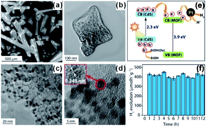 | ||
| Fig. 23 (a) SEM images of CdS@ZAVCl and (b–d) TEM images of CdS@ZAVCl-MOF. (e) Mechanism of water splitting by the CdS@ZAVCl photocatalyst (30 mg) using 0.5 wt% co-catalyst Pt at λ > 420 nm. (f) Stability tests of photocatalyst (CdS@ZAVCl-MOF) for 12 cycles of the water splitting reaction. Reproduced with permission.207 Copyright©2014 American Chemistry Society. | ||
In addition, MOFs have other functions in some photocatalytic systems. For example, Pt@MOF/Au composites have been successfully fabricated by Jiang and co-workers, where the presence of MOF did not only extend the light absorption but accelerated charge transfer from Au to Pt active sites (Fig. 24a). Also, hybrid photocatalysts containing Pt NPs and porphyrinic metal–organic frameworks (MOFs) and Pt/PCN-224(M) have been used for selective oxidation of aromatic alcohols (Fig. 24b). The excellent catalytic performance of Pt/PCN-224(M) resulted from the pronounced photothermal effect and singlet oxygen produced by cooperation between Pt NPs and PCN-224(Zn). In addition, competition between the Schottky junction and plasmonic effect may allow adjustment of the surface electronic state of Pt NPs by controlling the incident light intensity to achieve best catalytic performances.213–215 Luo et al. decorated ZIF-8 on electrostatic spinning TiO2 nanofibers (TiO2 ESNFs) to form a TiO2/ZIF-8 hybrid photocatalyst with great photocatalytic activity towards Rhodamine B (RhB) photodegradation since the N–Ti–O bond reduced the electron–hole pair recombination.216,217
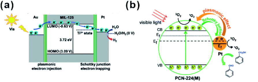 | ||
| Fig. 24 (a) Schematic illustration showing electron migration at two metal–MOF interfaces based on energy levels. Reproduced with permission.213 Copyright©2018 WILEY-VCH Verlag GmbH & Co. KGaA. (b) Proposed mechanism of 1O2 generation and electron transfer between Pt and PCN-224(M) during oxidation of benzyl alcohol over Pt/PCN-224(M) under visible-light irradiation. Reproduced with permission.214 Copyright©2017 American Chemistry Society. | ||
4. Conclusions and perspectives
In this review, we summarized the structure–performance relationships of MOF-based composites from a new perspective, focusing on identifying the functions of MOF moieties in practical applications. With the assistance of MOFs, composites always showed significantly enhanced or even novel properties when compared to single-component materials. For practical applications, MOFs can be employed as armors to protect catalytic species, as membranes to screen substrates or control molecular configuration, as active site supporters, as nanoreactors for some specific reactions, and so on. To be noticed, in many cases MOF components play more than one role.However, despite the progress in functional MOF-based composites, some challenges still limit their practical applications. For instance, the instability of the MOF structure constrains the application and recycling of MOF-based composites in some reactions, especially at high temperatures. Hence, the development of stable MOF structures for fabrication of MOF-based composites is necessary for better applications. On the other hand, despite the large number of synthesis methods of MOF-based composites, all of them still suffer from some limitations. Therefore, exploring novel universal approaches to construct specific functional MOF-based materials is important, especially for the precious control of guest species in MOF matrices. Moreover, more attention has been paid to environmentally sensitive MOF materials with structures responding to external stimuli, such as electrical or optical signals. The preparation of such MOFs will lead to new avenues for constructing intelligent functional materials by integrating environmentally sensitive MOFs with functional materials. In short, further development of MOF-based composites will clarify the structural–functional relationship of MOF-based composites and benefit the future design and fabrication of new MOF-based functional materials for various applications.
Conflicts of interest
There are no conflicts to declare.Acknowledgements
This work was supported by the National Key Research and Development Program of China (2017YFA0206500 and 2017YFA0206801) and the National Natural Science Foundation of China (21671163, 21721001, 21773190, and 21931009).Notes and references
- J. R. Long and O. M. Yaghi, Chem. Soc. Rev., 2009, 38, 1213–1214 RSC.
- J. R. Li, R. J. Kuppler and H. C. Zhou, Chem. Soc. Rev., 2009, 38, 1477–1504 RSC.
- D. J. Tranchemontagne, J. L. Mendoza-Cortes, M. O'Keeffe and O. M. Yaghi, Chem. Soc. Rev., 2009, 38, 1257–1283 RSC.
- M. Eddaoudi, D. B. Moler, H. Li, B. Chen, T. M. Reineke, M. O'Keeffe and O. M. Yaghi, Acc. Chem. Res., 2001, 34, 319–330 CrossRef CAS PubMed.
- H. Li, A. Laine, M. O'Keeffe and O. M. Yaghi, Science, 1999, 283, 1145–1147 CrossRef CAS PubMed.
- H. Li, M. Eddaoudi, M. O'Keeffe and O. M. Yaghi, Nature, 1999, 402, 276–279 CrossRef CAS.
- A. Cadiau, K. Adil, P. M. Bhatt, Y. Belmabkhout and M. Eddaoudi, Science, 2016, 353, 137–140 CrossRef CAS PubMed.
- J. Y. Lin, Science, 2016, 353, 121–122 CrossRef CAS PubMed.
- J. Lee, O. K. Farha, J. Roberts, K. A. Scheidt, S. T. Nguyen and J. T. Hupp, Chem. Soc. Rev., 2009, 38, 1450–1459 RSC.
- M. R. Tchalala, P. M. Bhatt, K. N. Chappanda, S. R. Tavares, K. Adil, Y. Belmabkhout, A. Shkurenko, A. Cadiau, N. Heymans, G. De Weireld, G. Maurin, K. N. Salama and M. Eddaoudi, Nat. Commun., 2019, 10, 1328 CrossRef CAS PubMed.
- I. Abánades Lázaro and R. S. Forgan, Coord. Chem. Rev., 2019, 380, 230–259 CrossRef.
- R. Dong, Z. Zhang, D. C. Tranca, S. Zhou, M. Wang, P. Adler, Z. Liao, F. Liu, Y. Sun, W. Shi, Z. Zhang, E. Zschech, S. C. B. Mannsfeld, C. Felser and X. Feng, Nat. Commun., 2018, 9, 2637 CrossRef PubMed.
- H. C. Zhou, J. R. Long and O. M. Yaghi, Chem. Rev., 2012, 112, 673–674 CrossRef CAS PubMed.
- H. Deng, S. Grunder, K. E. Cordova, C. Valente, H. Furukawa, M. Hmadeh, F. Gandara, A. C. Whalley, Z. Liu, S. Asahina, H. Kazumori, M. O'Keeffe, O. Terasaki, J. F. Stoddart and O. M. Yaghi, Science, 2012, 336, 1018–1023 CrossRef CAS PubMed.
- N. Stock and S. Biswas, Chem. Rev., 2012, 112, 933–969 CrossRef CAS PubMed.
- C. M. Doherty, D. Buso, A. J. Hill, S. Furukawa, S. Kitagawa and P. Falcaro, Acc. Chem. Res., 2014, 47, 396–405 CrossRef CAS PubMed.
- Z. Liang, C. Qu, W. Guo, R. Zou and Q. Xu, Adv. Mater., 2018, 30, 1702891 CrossRef PubMed.
- L. Chen, R. Luque and Y. Li, Chem. Soc. Rev., 2017, 46, 4614–4630 RSC.
- X. Lian, Y. Fang, E. Joseph, Q. Wang, J. Li, S. Banerjee, C. Lollar, X. Wang and H. C. Zhou, Chem. Soc. Rev., 2017, 46, 3386–3401 RSC.
- D. Y. Du, J. S. Qin, S. L. Li, Z. M. Su and Y. Q. Lan, Chem. Soc. Rev., 2014, 43, 4615–4632 RSC.
- A. Rossin, G. Tuci, L. Luconi and G. Giambastiani, ACS Catal., 2017, 7, 5035–5045 CrossRef CAS.
- S. Sundriyal, H. Kaur, S. K. Bhardwaj, S. Mishra, K.-H. Kim and A. Deep, Coord. Chem. Rev., 2018, 369, 15–38 CrossRef CAS.
- M. Zhao, K. Yuan, Y. Wang, G. Li, J. Guo, L. Gu, W. Hu, H. Zhao and Z. Tang, Nature, 2016, 539, 76–80 CrossRef CAS PubMed.
- K. M. Choi, K. Na, G. A. Somorjai and O. M. Yaghi, J. Am. Chem. Soc., 2015, 137, 7810–7816 CrossRef CAS PubMed.
- K. Sabyrov, J. Jiang, O. M. Yaghi and G. A. Somorjai, J. Am. Chem. Soc., 2017, 139, 12382–12385 CrossRef CAS PubMed.
- W. W. Zhan, Q. Kuang, J. Z. Zhou, X. J. Kong, Z. X. Xie and L. S. Zheng, J. Am. Chem. Soc., 2013, 135, 1926–1933 CrossRef CAS PubMed.
- Q. Yang, Q. Xu, S. H. Yu and H. L. Jiang, Angew. Chem., Int. Ed., 2016, 55, 3685–3689 CrossRef CAS PubMed.
- F. K. Shieh, S. C. Wang, C. I. Yen, C. C. Wu, S. Dutta, L. Y. Chou, J. V. Morabito, P. Hu, M. H. Hsu, K. C. Wu and C. K. Tsung, J. Am. Chem. Soc., 2015, 137, 4276–4279 CrossRef CAS PubMed.
- F. S. Liao, W. S. Lo, Y. S. Hsu, C. C. Wu, S. C. Wang, F. K. Shieh, J. V. Morabito, L. Y. Chou, K. C. Wu and C. K. Tsung, J. Am. Chem. Soc., 2017, 139, 6530–6533 CrossRef CAS PubMed.
- W.-H. Chen, M. Vázquez-González, A. Zoabi, R. Abu-Reziq and I. Willner, Nat. Catal., 2018, 1, 689–695 CrossRef CAS.
- Q. Yang, Q. Xu and H. L. Jiang, Chem. Soc. Rev., 2017, 46, 4774–4808 RSC.
- L. Jiao, Y. Wang, H. L. Jiang and Q. Xu, Adv. Mater., 2018, 30, 1703663 CrossRef PubMed.
- Q. L. Zhu and Q. Xu, Chem. Soc. Rev., 2014, 43, 5468–5512 RSC.
- Y. B. Huang, J. Liang, X. S. Wang and R. Cao, Chem. Soc. Rev., 2017, 46, 126–157 RSC.
- C. D. Wu and M. Zhao, Adv. Mater., 2017, 29, 1605446 CrossRef PubMed.
- Y. Liu, W. Xuan and Y. Cui, Adv. Mater., 2010, 22, 4112–4135 CrossRef CAS PubMed.
- A. Dhakshinamoorthy and H. Garcia, Chem. Soc. Rev., 2012, 41, 5262–5284 RSC.
- S. Li and F. Huo, Nanoscale, 2015, 7, 7482–7501 RSC.
- J. Yu, C. Mu, B. Yan, X. Qin, C. Shen, H. Xue and H. Pang, Mater. Horiz., 2017, 4, 557–569 RSC.
- G. Lu, S. Li, Z. Guo, O. K. Farha, B. G. Hauser, X. Qi, Y. Wang, X. Wang, S. Han, X. Liu, J. S. DuChene, H. Zhang, Q. Zhang, X. Chen, J. Ma, S. C. Loo, W. D. Wei, Y. Yang, J. T. Hupp and F. Huo, Nat. Chem., 2012, 4, 310–316 CrossRef CAS PubMed.
- W. Zhang, Y. Liu, G. Lu, Y. Wang, S. Li, C. Cui, J. Wu, Z. Xu, D. Tian, W. Huang, J. S. DuCheneu, W. D. Wei, H. Chen, Y. Yang and F. Huo, Adv. Mater., 2015, 27, 2923–2929 CrossRef CAS PubMed.
- P. Hu, J. Zhuang, L. Y. Chou, H. K. Lee, X. Y. Ling, Y. C. Chuang and C. K. Tsung, J. Am. Chem. Soc., 2014, 136, 10561–10564 CrossRef CAS PubMed.
- Y. Mao, J. Li, W. Cao, Y. Ying, P. Hu, Y. Liu, L. Sun, H. Wang, C. Jin and X. Peng, Nat. Commun., 2014, 5, 5532 CrossRef PubMed.
- C. H. Kuo, Y. Tang, L. Y. Chou, B. T. Sneed, C. N. Brodsky, Z. Zhao and C. K. Tsung, J. Am. Chem. Soc., 2012, 134, 14345–14348 CrossRef CAS PubMed.
- Y. Liu, W. Zhang, S. Li, C. Cui, J. Wu, H. Chen and F. Huo, Chem. Mater., 2014, 26, 1119–1125 CrossRef CAS.
- W. T. Koo, S. J. Kim, J. S. Jang, D. H. Kim and I. D. Kim, Adv. Sci., 2019, 6, 1970126 CrossRef.
- Z. Li, T. M. Rayder, L. Luo, J. A. Byers and C. K. Tsung, J. Am. Chem. Soc., 2018, 140, 8082–8085 CrossRef CAS.
- A. Aijaz, A. Karkamkar, Y. J. Choi, N. Tsumori, E. Ronnebro, T. Autrey, H. Shioyama and Q. Xu, J. Am. Chem. Soc., 2012, 134, 13926–13929 CrossRef CAS PubMed.
- B. Yuan, Y. Pan, Y. Li, B. Yin and H. Jiang, Angew. Chem., Int. Ed., 2010, 49, 4054–4058 CrossRef CAS PubMed.
- J. Yang, H. Ye, F. Zhao and B. Zeng, ACS Appl. Mater. Interfaces, 2016, 8, 20407–20414 CrossRef CAS PubMed.
- Z. Zhang, X. Cui, W. Yuan, Q. Yang, H. Liu, H. Xu and H.-L. Jiang, Inorg. Chem. Front., 2018, 5, 29–38 RSC.
- Q. L. Zhu, J. Li and Q. Xu, J. Am. Chem. Soc., 2013, 135, 10210–10213 CrossRef CAS.
- Y.-Z. Chen, Q. Xu, S.-H. Yu and H.-L. Jiang, Small, 2015, 11, 71–76 CrossRef CAS PubMed.
- Y. H. Zhou, Q. Yang, Y. Z. Chen and H. L. Jiang, Chem. Commun., 2017, 53, 12361–12364 RSC.
- L. Chen, B. Huang, X. Qiu, X. Wang, R. Luque and Y. Li, Chem. Sci., 2016, 7, 228–233 RSC.
- L. Chen, X. Chen, H. Liu and Y. Li, Small, 2015, 11, 2642–2648 CrossRef CAS PubMed.
- Y. Fang, J. Li, T. Togo, F. Jin, Z. Xiao, L. Liu, H. Drake, X. Lian and H.-C. Zhou, Chem, 2018, 4, 555–563 CAS.
- Y. Fang, Z. Xiao, J. Li, C. Lollar, L. Liu, X. Lian, S. Yuan, S. Banerjee, P. Zhang and H.-C. Zhou, Angew. Chem., Int. Ed., 2018, 57, 5283–5287 CrossRef CAS PubMed.
- M. Hu, S. Zhao, S. Liu, C. Chen, W. Chen, W. Zhu, C. Liang, W. C. Cheong, Y. Wang, Y. Yu, Q. Peng, K. Zhou, J. Li and Y. Li, Adv. Mater., 2018, 1801878, DOI:10.1002/adma.201801878.
- M. Li, C. Ma, X. Liu, J. Su, X. Cui and Y. He, Chem. Sci., 2018, 9, 5912–5918 RSC.
- Z. G. Gu, D. J. Li, C. Zheng, Y. Kang, C. Wöll and J. Zhang, Angew. Chem., Int. Ed., 2017, 56, 6853–6858 CrossRef CAS PubMed.
- Z. Li, R. Yu, J. Huang, Y. Shi, D. Zhang, X. Zhong, D. Wang, Y. Wu and Y. Li, Nat. Commun., 2015, 6, 8248 CrossRef CAS PubMed.
- Q. Yang, W. Liu, B. Wang, W. Zhang, X. Zeng, C. Zhang, Y. Qin, X. Sun, T. Wu, J. Liu, F. Huo and J. Lu, Nat. Commun., 2017, 8, 14429 CrossRef CAS PubMed.
- R. Riccò, O. Linder-Patton, K. Sumida, M. J. Styles, K. Liang, H. Amenitsch, C. J. Doonan and P. Falcaro, Chem. Mater., 2018, 30, 5630–5638 CrossRef.
- W. Zhan, Y. He, J. Guo, L. Chen, X. Kong, H. Zhao, Q. Kuang, Z. Xie and L. Zheng, Nanoscale, 2016, 8, 13181–13185 RSC.
- L. Chen, H. Li, W. Zhan, Z. Cao, J. Chen, Q. Jiang, Y. Jiang, Z. Xie, Q. Kuang and L. Zheng, ACS Appl. Mater. Interfaces, 2016, 8, 31059–31066 CrossRef CAS.
- L. N. Chen, H. Q. Li, M. W. Yan, C. F. Yuan, W. W. Zhan, Y. Q. Jiang, Z. X. Xie, Q. Kuang and L. S. Zheng, Small, 2017, 13, 1700683 CrossRef PubMed.
- G. Cai, W. Zhang, L. Jiao, S. H. Yu and H. L. Jiang, Chem, 2017, 2, 791–802 CAS.
- N. Zhang, Q. Shao, P. Wang, X. Zhu and X. Huang, Small, 2018, 14, 1704318 CrossRef PubMed.
- W. T. Koo, S. J. Kim, J. S. Jang, D. H. Kim and I. D. Kim, Adv. Sci., 2019, 6, 1970126 CrossRef.
- M. Drobek, J. H. Kim, M. Bechelany, C. Vallicari, A. Julbe and S. S. Kim, ACS Appl. Mater. Interfaces, 2016, 8, 8323–8328 CrossRef CAS.
- H. Tian, H. Fan, M. Li and L. Ma, ACS Sens., 2016, 1, 243–250 CrossRef CAS.
- M. S. Yao, W. X. Tang, G. E. Wang, B. Nath and G. Xu, Adv. Mater., 2016, 28, 5229–5234 CrossRef CAS.
- J. Zhuang, L. Y. Chou, B. T. Sneed, Y. Cao, P. Hu, L. Feng and C. K. Tsung, Small, 2015, 11, 5551–5555 CrossRef CAS PubMed.
- L. Chen, W. Zhan, H. Fang, Z. Cao, C. Yuan, Z. Xie, Q. Kuang and L. Zheng, Chem.–Eur. J., 2017, 23, 11397–11403 CrossRef CAS.
- L. He, Y. Liu, J. Liu, Y. Xiong, J. Zheng, Y. Liu and Z. Tang, Angew. Chem., Int. Ed., 2013, 52, 3741–3745 CrossRef CAS PubMed.
- H. Liu, L. Chang, C. Bai, L. Chen, R. Luque and Y. Li, Angew. Chem., Int. Ed., 2016, 55, 5019–5023 CrossRef CAS PubMed.
- H. Liu, L. Chang, L. Chen and Y. Li, J. Mater. Chem. A, 2015, 3, 8028–8033 RSC.
- X. F. Yang, A. Wang, B. Qiao, J. Li, J. Liu and T. Zhang, Acc. Chem. Res., 2013, 46, 1740–1748 CrossRef CAS PubMed.
- J. N. Kuhn, W. Huang, C. K. Tsung, Y. Zhang and G. A. Somorjai, J. Am. Chem. Soc., 2008, 130, 14026–14027 CrossRef CAS PubMed.
- L. N. Chen, K. P. Hou, Y. S. Liu, Z. Y. Qi, Q. Zheng, Y. H. Lu, J. Y. Chen, J. L. Chen, C. W. Pao, S. B. Wang, Y. B. Li, S. H. Xie, F. D. Liu, D. Prendergast, L. E. Klebanoff, V. Stavila, M. D. Allendorf, J. Guo, L. S. Zheng, J. Su and G. A. Somorjai, J. Am. Chem. Soc., 2019, 141, 17995–17999 CrossRef CAS PubMed.
- S. Ji, Y. Chen, S. Zhao, W. Chen, L. Shi, Y. Wang, J. Dong, Z. Li, F. Li, C. Chen, Q. Peng, J. Li, D. Wang and Y. Li, Angew. Chem., Int. Ed., 2019, 58, 4271–4275 CrossRef CAS PubMed.
- J. Li, W. Wang, W. Chen, Q. Gong, J. Luo, R. Lin, H. Xin, H. Zhang, D. Wang, Q. Peng, W. Zhu, C. Chen and Y. Li, Nano Res., 2018, 11, 4774–4785 CrossRef CAS.
- M. Mon, M. A. Rivero-Crespo, J. Ferrando-Soria, A. Vidal-Moya, M. Boronat, A. Leyva-Perez, A. Corma, J. C. Hernandez-Garrido, M. Lopez-Haro, J. J. Calvino, G. Ragazzon, A. Credi, D. Armentano and E. Pardo, Angew. Chem., Int. Ed., 2018, 57, 6186–6191 CrossRef CAS PubMed.
- D. Aulakh, L. Liu, J. R. Varghese, H. Xie, T. Islamoglu, K. Duell, C. W. Kung, C. E. Hsiung, Y. Zhang, R. J. Drout, O. K. Farha, K. R. Dunbar, Y. Han and M. Wriedt, J. Am. Chem. Soc., 2019, 141, 2997–3005 CrossRef CAS PubMed.
- B. Li, J. G. Ma and P. Cheng, Angew. Chem., Int. Ed., 2018, 57, 6834–6837 CrossRef CAS PubMed.
- R. J. Drout, L. Robison and O. K. Farha, Coord. Chem. Rev., 2019, 381, 151–160 CrossRef CAS.
- Y. Chen, P. Li, J. A. Modica, R. J. Drout and O. K. Farha, J. Am. Chem. Soc., 2018, 140, 5678–5681 CrossRef CAS PubMed.
- P. Li, Q. Chen, T. C. Wang, N. A. Vermeulen, B. L. Mehdi, A. Dohnalkova, N. D. Browning, D. Shen, R. Anderson, D. A. Gómez-Gualdrón, F. M. Cetin, J. Jagiello, A. M. Asiri, J. F. Stoddart and O. K. Farha, Chem, 2018, 4, 1022–1034 CAS.
- D. Feng, T. F. Liu, J. Su, M. Bosch, Z. Wei, W. Wan, D. Yuan, Y. P. Chen, X. Wang, K. Wang, X. Lian, Z. Y. Gu, J. Park, X. Zou and H. C. Zhou, Nat. Commun., 2015, 6, 5979 CrossRef PubMed.
- H. Bux, C. Chmelik, R. Krishna and J. Caro, J. Membr. Sci., 2011, 369, 284–289 CrossRef CAS.
- J. W. M. Osterrieth, D. Wright, H. Noh, C. W. Kung, D. Vulpe, A. Li, J. E. Park, R. P. Van Duyne, P. Z. Moghadam, J. J. Baumberg, O. K. Farha and D. Fairen-Jimenez, J. Am. Chem. Soc., 2019, 141, 3893–3900 CrossRef CAS PubMed.
- M. M. Wanderley, C. Wang, C. D. Wu and W. Lin, J. Am. Chem. Soc., 2012, 134, 9050–9053 CrossRef CAS PubMed.
- L. Chen, T. Wang, Y. Xue, X. Zhou, J. Zhou, X. Cheng, Z. Xie, Q. Kuang and L. Zheng, Adv. Mater. Interfaces, 2018, 51801168 Search PubMed.
- S. Wang, Y. Fan, J. Teng, Y. Z. Fan, J. J. Jian, H. P. Wang, H. Grützmacher, D. Wang and C. Y. Su, Small, 2016, 12, 5702–5709 CrossRef CAS PubMed.
- Y. Liu, S. Liu, D. He, N. Li, Y. Ji, Z. Zheng, F. Luo, S. Liu, Z. Shi and C. Hu, J. Am. Chem. Soc., 2015, 137, 12697–12703 CrossRef CAS PubMed.
- L. Chen, H. Chen, R. Luque and Y. Li, Chem. Sci., 2014, 5, 3708–3714 RSC.
- M. S. Yao, L. A. Cao, Y. X. Tang, G. E. Wang, R. H. Liu, P. N. Kumar, G. D. Wu, W. H. Deng, W. J. Hong and G. Xu, J. Mater. Chem. A, 2019, 7, 18397–18403 RSC.
- M. S. Yao, J. W. Xiu, Q. Q. Huang, W. H. Li, W. W. Wu, A. Q. Wu, L. A. Cao, W. H. Deng, G. E. Wang and G. Xu, Angew. Chem., Int. Ed., 2019, 58, 14915–14919 CrossRef CAS PubMed.
- X. Zhao, L. Zhou, W. Zhang, C. Hu, L. Dai, L. Ren, B. Wu, G. Fu and N. Zheng, Chem, 2018, 4, 1080–1091 CAS.
- G. Chen, C. Xu, X. Huang, J. Ye, L. Gu, G. Li, Z. Tang, B. Wu, H. Yang, Z. Zhao, Z. Zhou, G. Fu and N. Zheng, Nat. Mater., 2016, 15, 564–569 CrossRef CAS PubMed.
- C. J. Kliewer, M. Bieri and G. A. Somorjai, J. Am. Chem. Soc., 2009, 131, 9958–9966 CrossRef CAS PubMed.
- G. Kennedy, L. R. Baker and G. A. Somorjai, Angew. Chem., Int. Ed., 2014, 53, 3405–3408 CrossRef CAS PubMed.
- B. Wu, H. Huang, J. Yang, N. Zheng and G. Fu, Angew. Chem., Int. Ed., 2012, 51, 3440–3443 CrossRef CAS PubMed.
- Z. Guo, C. Xiao, R. V. Maligal-Ganesh, L. Zhou, T. W. Goh, X. Li, D. Tesfagaber, A. Thiel and W. Huang, ACS Catal., 2014, 4, 1340–1348 CrossRef CAS.
- K. Yuan, T. Song, D. Wang, X. Zhang, X. Gao, Y. Zou, H. Dong, Z. Tang and W. Hu, Angew. Chem., Int. Ed., 2018, 57, 5708–5713 CrossRef CAS PubMed.
- H. Liu, L. Chang, L. Chen and Y. Li, ChemCatChem, 2016, 8, 946–951 CrossRef CAS.
- L. Chen, H. Chen and Y. Li, Chem. Commun., 2014, 50, 14752–14755 RSC.
- W. Zhang, B. Zheng, W. Shi, X. Chen, Z. Xu, S. Li, Y. R. Chi, Y. Yang, J. Lu, W. Huang and F. Huo, Adv. Mater., 2018, 30, 1800643 CrossRef PubMed.
- T. W. Goh, C. K. Tsung and W. Huang, ACS Appl. Mater. Interfaces, 2019, 11, 23254–23260 CrossRef CAS PubMed.
- C. J. Stephenson, C. L. Whitford, P. C. Stair, O. K. Farha and J. T. Hupp, ChemCatChem, 2016, 8, 855–860 CrossRef CAS.
- K. Na, K. M. Choi, O. M. Yaghi and G. A. Somorjai, Nano Lett., 2014, 14, 5979–5983 CrossRef CAS PubMed.
- J. Yang, F. Zhang, H. Lu, X. Hong, H. Jiang, Y. Wu and Y. Li, Angew. Chem., Int. Ed., 2015, 54, 10889–10893 CrossRef CAS PubMed.
- M. Zahmakiran, Dalton Trans., 2012, 41, 12690–12696 RSC.
- J. S. Seo, D. Whang, H. Lee, S. I. Jun, J. Oh, Y. J. Jeon and K. Kim, Nature, 2000, 404, 982–986 CrossRef CAS PubMed.
- M. Yoon, R. Srirambalaji and K. Kim, Chem. Rev., 2012, 112, 1196–1231 CrossRef CAS PubMed.
- S. Bhattacharjee, M. Khan, X. Li, Q.-L. Zhu and X.-T. Wu, Catalysts, 2018, 8, 120 CrossRef.
- C. D. Wu, A. Hu, L. Zhang and W. Lin, J. Am. Chem. Soc., 2005, 127, 8940–8941 CrossRef CAS PubMed.
- F. Song, C. Wang, J. M. Falkowski, L. Ma and W. Lin, J. Am. Chem. Soc., 2010, 132, 15390–15398 CrossRef CAS PubMed.
- T. Bogaerts, A. Van Yperen-De Deyne, Y. Y. Liu, F. Lynen, V. Van Speybroeck and P. Van Der Voort, Chem. Commun., 2013, 49, 8021–8023 RSC.
- S. H. Cho, B. Ma, S. T. Nguyen, J. T. Hupp and T. E. Albrecht-Schmitt, Chem. Commun., 2006, 2563–2565 RSC.
- X. Chen, Y. Peng, X. Han, Y. Liu, X. Lin and Y. Cui, Nat. Commun., 2017, 8, 2171 CrossRef PubMed.
- Q. Han, B. Qi, W. Ren, C. He, J. Niu and C. Duan, Nat. Commun., 2015, 6, 10007 CrossRef PubMed.
- B. Chen, S. Xiang and G. Qian, Acc. Chem. Res., 2010, 43, 1115–1124 CrossRef CAS PubMed.
- N. L. Rosi, J. Eckert, M. Eddaoudi, D. T. Vodak, J. Kim, M. O'Keeffe and O. M. Yaghi, Science, 2003, 300, 1127–1129 CrossRef CAS PubMed.
- J. Sculley, D. Yuan and H.-C. Zhou, Energy Environ. Sci., 2011, 4, 2721 RSC.
- I. Luz, M. Soukri and M. Lail, Chem. Commun., 2018, 54, 8462–8465 RSC.
- C. A. Trickett, A. Helal, B. A. Al-Maythalony, Z. H. Yamani, K. E. Cordova and O. M. Yaghi, Nat. Rev. Mater., 2017, 2, 17045 CrossRef CAS.
- Y. S. Bae and R. Q. Snurr, Angew. Chem., Int. Ed., 2011, 50, 11586–11596 CrossRef CAS PubMed.
- S. Chaemchuen, N. A. Kabir, K. Zhou and F. Verpoort, Chem. Soc. Rev., 2013, 42, 9304–9332 RSC.
- R. Li, J. Hu, M. Deng, H. Wang, X. Wang, Y. Hu, H. L. Jiang, J. Jiang, Q. Zhang, Y. Xie and Y. Xiong, Adv. Mater., 2014, 26, 4783–4788 CrossRef CAS.
- X. Deng, R. Li, S. Wu, L. Wang, J. Hu, J. Ma, W. Jiang, N. Zhang, X. Zheng, C. Gao, L. Wang, Q. Zhang, J. Zhu and Y. Xiong, J. Am. Chem. Soc., 2019, 141, 10924–10929 CrossRef CAS PubMed.
- L. Sun, Y. Yun, H. Sheng, Y. Du, Y. Ding, P. Wu, P. Li and M. Zhu, J. Mater. Chem. A, 2018, 6, 15371–15376 RSC.
- X. Liu, L. He, J. Zheng, J. Guo, F. Bi, X. Ma, K. Zhao, Y. Liu, R. Song and Z. Tang, Adv. Mater., 2015, 27, 3273–3277 CrossRef CAS PubMed.
- G. Zhang, H. Sheng, D. Chen, N. Li, Q. Xu, H. Li, J. He and J. Lu, Chem.–Eur. J., 2018, 24, 15019–15025 CrossRef CAS PubMed.
- M.-X. Wu, J. Gao, F. Wang, J. Yang, N. Song, X. Jin, P. Mi, J. Tian, J. Luo, F. Liang and Y.-W. Yang, Small, 2018, 14, 1704440 CrossRef PubMed.
- M. Angamuthu, G. Satishkumar and M. V. Landau, Microporous Mesoporous Mater., 2017, 251, 58–68 CrossRef CAS.
- F. Ke, L.-G. Qiu, Y.-P. Yuan, X. Jiang and J.-F. Zhu, J. Mater. Chem., 2012, 22, 9497 RSC.
- Y. Cui, R. Song, J. Yu, M. Liu, Z. Wang, C. Wu, Y. Yang, Z. Wang, B. Chen and G. Qian, Adv. Mater., 2015, 27, 1420–1425 CrossRef CAS PubMed.
- D. M. Chen, N. N. Zhang, C. S. Liu and M. Du, ACS Appl. Mater. Interfaces, 2017, 9, 24671–24677 CrossRef CAS PubMed.
- L. Xu, Y. Xu, X. Li, Z. Wang, T. Sun and X. Zhang, Dalton Trans., 2018, 47, 16696–16703 RSC.
- D. J. Xiao, E. D. Bloch, J. A. Mason, W. L. Queen, M. R. Hudson, N. Planas, J. Borycz, A. L. Dzubak, P. Verma, K. Lee, F. Bonino, V. Crocella, J. Yano, S. Bordiga, D. G. Truhlar, L. Gagliardi, C. M. Brown and J. R. Long, Nat. Chem., 2014, 6, 590–595 CrossRef CAS PubMed.
- X. F. Lu, P. Q. Liao, J. W. Wang, J. X. Wu, X. W. Chen, C. T. He, J. P. Zhang, G. R. Li and X. M. Chen, J. Am. Chem. Soc., 2016, 138, 8336–8339 CrossRef CAS PubMed.
- D. Shi, R. Zheng, M. J. Sun, X. Cao, C. X. Sun, C. J. Cui, C. S. Liu, J. Zhao and M. Du, Angew. Chem., Int. Ed., 2017, 56, 14637–14641 CrossRef CAS PubMed.
- S. Zhao, Y. Wang, J. Dong, C.-T. He, H. Yin, P. An, K. Zhao, X. Zhang, C. Gao, L. Zhang, J. Lv, J. Wang, J. Zhang, A. M. Khattak, N. A. Khan, Z. Wei, J. Zhang, S. Liu, H. Zhao and Z. Tang, Nat. Energy, 2016, 1, 16184 CrossRef CAS.
- J. Duan, S. Chen and C. Zhao, Nat. Commun., 2017, 8, 15341 CrossRef CAS PubMed.
- L. Cao, Z. Lin, W. Shi, Z. Wang, C. Zhang, X. Hu, C. Wang and W. Lin, J. Am. Chem. Soc., 2017, 139, 7020–7029 CrossRef CAS PubMed.
- L. Cao, Z. Lin, F. Peng, W. Wang, R. Huang, C. Wang, J. Yan, J. Liang, Z. Zhang, T. Zhang, L. Long, J. Sun and W. Lin, Angew. Chem., Int. Ed., 2016, 55, 4962–4966 CrossRef CAS PubMed.
- W. Shi, L. Cao, H. Zhang, X. Zhou, B. An, Z. Lin, R. Dai, J. Li, C. Wang and W. Lin, Angew. Chem., Int. Ed., 2017, 56, 9704–9709 CrossRef CAS PubMed.
- O. K. Farha, A. M. Shultz, A. A. Sarjeant, S. T. Nguyen and J. T. Hupp, J. Am. Chem. Soc., 2011, 133, 5652–5655 CrossRef CAS PubMed.
- D. Feng, W. C. Chung, Z. Wei, Z. Y. Gu, H. L. Jiang, Y. P. Chen, D. J. Darensbourg and H. C. Zhou, J. Am. Chem. Soc., 2013, 135, 17105–17110 CrossRef CAS PubMed.
- Y. Wang, H. Cui, Z. W. Wei, H. P. Wang, L. Zhang and C. Y. Su, Chem. Sci., 2017, 8, 775–780 RSC.
- X. Fang, Q. Shang, Y. Wang, L. Jiao, T. Yao, Y. Li, Q. Zhang, Y. Luo and H. L. Jiang, Adv. Mater., 2018, 30, 1705112 CrossRef PubMed.
- N. Kornienko, Y. Zhao, C. S. Kley, C. Zhu, D. Kim, S. Lin, C. J. Chang, O. M. Yaghi and P. Yang, J. Am. Chem. Soc., 2015, 137, 14129–14135 CrossRef CAS PubMed.
- H. Zhang, J. Wei, J. Dong, G. Liu, L. Shi, P. An, G. Zhao, J. Kong, X. Wang, X. Meng, J. Zhang and J. Ye, Angew. Chem., Int. Ed., 2016, 55, 14310–14314 CrossRef CAS PubMed.
- L. Meng, Q. Cheng, C. Kim, W. Y. Gao, L. Wojtas, Y. S. Chen, M. J. Zaworotko, X. P. Zhang and S. Ma, Angew. Chem., Int. Ed., 2012, 51, 10082–10085 CrossRef CAS PubMed.
- D. Kim, D. R. Whang and S. Y. Park, J. Am. Chem. Soc., 2016, 138, 8698–8701 CrossRef CAS PubMed.
- L. Ye, J. Liu, Y. Gao, C. Gong, M. Addicoat, T. Heine, C. Wöll and L. Sun, J. Mater. Chem. A, 2016, 4, 15320–15326 RSC.
- T. Kajiwara, M. Fujii, M. Tsujimoto, K. Kobayashi, M. Higuchi, K. Tanaka and S. Kitagawa, Angew. Chem., Int. Ed., 2016, 55, 2697–2700 CrossRef CAS PubMed.
- R. Srirambalaji, S. Hong, R. Natarajan, M. Yoon, R. Hota, Y. Kim, Y. Ho Ko and K. Kim, Chem. Commun., 2012, 48, 11650–11652 RSC.
- J. Chen, R. Liu, Y. Guo, L. Chen and H. Gao, ACS Catal., 2014, 5, 722–733 CrossRef.
- M. Martis, K. Mori, K. Fujiwara, W.-S. Ahn and H. Yamashita, J. Phys. Chem. C, 2013, 117, 22805–22810 CrossRef CAS.
- M. Zhao, K. Deng, L. He, Y. Liu, G. Li, H. Zhao and Z. Tang, J. Am. Chem. Soc., 2014, 136, 1738–1741 CrossRef CAS PubMed.
- X. Li, B. Zhang, L. Tang, T. W. Goh, S. Qi, A. Volkov, Y. Pei, Z. Qi, C. K. Tsung, L. Stanley and W. Huang, Angew. Chem., Int. Ed., 2017, 56, 16371–16375 CrossRef CAS PubMed.
- X. Zhang, L. Chen, Y. Li, H. Li, Z. Xie, Q. Kuang and L. Zheng, Dalton Trans., 2019, 48, 5515–5519 RSC.
- C. Wang, K. E. deKrafft and W. Lin, J. Am. Chem. Soc., 2012, 134, 7211–7214 CrossRef CAS PubMed.
- K. M. Choi, D. Kim, B. Rungtaweevoranit, C. A. Trickett, J. T. Barmanbek, A. S. Alshammari, P. Yang and O. M. Yaghi, J. Am. Chem. Soc., 2017, 139, 356–362 CrossRef CAS PubMed.
- H. Liu, Y. Li, H. Jiang, C. Vargas and R. Luque, Chem. Commun., 2012, 48, 8431–8433 RSC.
- H. Liu, Y. Li, R. Luque and H. Jiang, Adv. Synth. Catal., 2011, 353, 3107–3113 CrossRef CAS.
- Y. Pan, B. Yuan, Y. Li and D. He, Chem. Commun., 2010, 46, 2280–2282 RSC.
- F. G. Cirujano, A. Leyva-Pérez, A. Corma and F. X. Llabrés i Xamena, ChemCatChem, 2013, 5, 538–549 CrossRef CAS.
- Y.-Z. Chen, Y.-X. Zhou, H. Wang, J. Lu, T. Uchida, Q. Xu, S.-H. Yu and H.-L. Jiang, ACS Catal., 2015, 5, 2062–2069 CrossRef CAS.
- S. Ling and B. Slater, Chem. Sci., 2016, 7, 4706–4712 RSC.
- F. Vermoortele, M. Vandichel, B. Van de Voorde, R. Ameloot, M. Waroquier, V. Van Speybroeck and D. E. De Vos, Angew. Chem., Int. Ed., 2012, 51, 4887–4890 CrossRef CAS PubMed.
- X. Li, Z. Guo, C. Xiao, T. W. Goh, D. Tesfagaber and W. Huang, ACS Catal., 2014, 4, 3490–3497 CrossRef CAS.
- R. Limvorapitux, L.-Y. Chou, A. P. Young, C.-K. Tsung and S. T. Nguyen, ACS Catal., 2017, 7, 6691–6698 CrossRef CAS.
- B. Rungtaweevoranit, J. Baek, J. R. Araujo, B. S. Archanjo, K. M. Choi, O. M. Yaghi and G. A. Somorjai, Nano Lett., 2016, 16, 7645–7649 CrossRef CAS PubMed.
- N. Tsumori, L. Chen, Q. Wang, Q.-L. Zhu, M. Kitta and Q. Xu, Chem, 2018, 4, 845–856 CAS.
- Y. Yamada, C. K. Tsung, W. Huang, Z. Huo, S. E. Habas, T. Soejima, C. E. Aliaga, G. A. Somorjai and P. Yang, Nat. Chem., 2011, 3, 372–376 CrossRef CAS PubMed.
- X. Peng, K. Cheng, J. Kang, B. Gu, X. Yu, Q. Zhang and Y. Wang, Angew. Chem., Int. Ed., 2015, 54, 4553–4556 CrossRef CAS PubMed.
- J. H. Bang and K. S. Suslick, Adv. Mater., 2010, 22, 1039–1059 CrossRef CAS PubMed.
- G. Huang, Q. Yang, Q. Xu, S. H. Yu and H. L. Jiang, Angew. Chem., Int. Ed., 2016, 55, 7379–7383 CrossRef CAS PubMed.
- L. Li, Q. Yang, S. Chen, X. Hou, B. Liu, J. Lu and H. L. Jiang, Chem. Commun., 2017, 53, 10026–10029 RSC.
- X. Chen, P. Qian, T. Zhang, Z. Xu, C. Fang, X. Xu, W. Chen, P. Wu, Y. Shen, S. Li, J. Wu, B. Zheng, W. Zhang and F. Huo, Chem. Commun., 2018, 54, 3936–3939 RSC.
- R. Fang, H. Liu, R. Luque and Y. Li, Green Chem., 2015, 17, 4183–4188 RSC.
- M. Ding and H.-L. Jiang, ACS Catal., 2018, 8, 3194–3201 CrossRef CAS.
- J. Park, J. R. Li, Y. P. Chen, J. Yu, A. A. Yakovenko, Z. U. Wang, L. B. Sun, P. B. Balbuena and H. C. Zhou, Chem. Commun., 2012, 48, 9995–9997 RSC.
- B. Li, K. Leng, Y. Zhang, J. J. Dynes, J. Wang, Y. Hu, D. Ma, Z. Shi, L. Zhu, D. Zhang, Y. Sun, M. Chrzanowski and S. Ma, J. Am. Chem. Soc., 2015, 137, 4243–4248 CrossRef CAS PubMed.
- M. H. Beyzavi, N. A. Vermeulen, A. J. Howarth, S. Tussupbayev, A. B. League, N. M. Schweitzer, J. R. Gallagher, A. E. Platero-Prats, N. Hafezi, A. A. Sarjeant, J. T. Miller, K. W. Chapman, J. F. Stoddart, C. J. Cramer, J. T. Hupp and O. K. Farha, J. Am. Chem. Soc., 2015, 137, 13624–13631 CrossRef CAS PubMed.
- F. Zhang, Y. Wei, X. Wu, H. Jiang, W. Wang and H. Li, J. Am. Chem. Soc., 2014, 136, 13963–13966 CrossRef CAS PubMed.
- C. Chizallet, S. Lazare, D. Bazer-Bachi, F. Bonnier, V. Lecocq, E. Soyer, A. A. Quoineaud and N. Bats, J. Am. Chem. Soc., 2010, 132, 12365–12377 CrossRef CAS PubMed.
- P. V. Dau and S. M. Cohen, Inorg. Chem., 2015, 54, 3134–3138 CrossRef CAS PubMed.
- X. Zhang, L. Chen, Y. Li, H. Li, Z. Xie, Q. Kuang and L. Zheng, Dalton Trans., 2019, 48, 5515–5519 RSC.
- A. Carne-Sanchez, I. Imaz, M. Cano-Sarabia and D. Maspoch, Nat. Chem., 2013, 5, 203–211 CrossRef CAS PubMed.
- Y. Ma, G. Xu, F. Wei, Y. Cen, X. Xu, M. Shi, X. Cheng, Y. Chai, M. Sohail and Q. Hu, ACS Appl. Mater. Interfaces, 2018, 10, 20801–20805 CrossRef CAS PubMed.
- W. Zhang, L. Wang, K. Wang, M. U. Khan, M. Wang, H. Li and J. Zeng, Small, 2017, 13, 1602583 CrossRef PubMed.
- L. Chen, X. Zhang, J. Zhou, Z. Xie, Q. Kuang and L. Zheng, Nanoscale, 2019, 11, 3292–3299 RSC.
- J. H. Zhao, Y. Yang, J. X. Che, J. Zuo, X. H. Li, Y. Z. Hu, X. W. Dong, L. Gao and X. Y. Liu, Chem.–Eur. J., 2018, 24, 9903–9909 CrossRef CAS PubMed.
- Z. Xu, G. Xiao, H. Li, Y. Shen, J. Zhang, T. Pan, X. Chen, B. Zheng, J. Wu, S. Li, W. Zhang, W. Huang and F. Huo, Adv. Funct. Mater., 2018, 28, 1802479 CrossRef.
- Q. Wang, X. Zhang, L. Huang, Z. Zhang and S. Dong, Angew. Chem., Int. Ed., 2017, 56, 16082–16085 CrossRef CAS PubMed.
- J.-D. Xiao, D. Li and H.-L. Jiang, Sci. China: Chem., 2018, 48, 1058–1075 Search PubMed.
- Y. Cui, J. Zhang, H. He and G. Qian, Chem. Soc. Rev., 2018, 47, 5740–5785 RSC.
- Y. Horiuchi, T. Toyao, M. Saito, K. Mochizuki, M. Iwata, H. Higashimura, M. Anpo and M. Matsuoka, J. Phys. Chem. C, 2012, 116, 20848–20853 CrossRef CAS.
- A. Fateeva, P. A. Chater, C. P. Ireland, A. A. Tahir, Y. Z. Khimyak, P. V. Wiper, J. R. Darwent and M. J. Rosseinsky, Angew. Chem., Int. Ed., 2012, 51, 7440–7444 CrossRef CAS PubMed.
- X. J. Kong, Z. Lin, Z. M. Zhang, T. Zhang and W. Lin, Angew. Chem., Int. Ed., 2016, 55, 6411–6416 CrossRef CAS PubMed.
- G. Paille, M. Gomez-Mingot, C. Roch-Marchal, B. Lassalle-Kaiser, P. Mialane, M. Fontecave, C. Mellot-Draznieks and A. Dolbecq, J. Am. Chem. Soc., 2018, 140, 3613–3618 CrossRef CAS PubMed.
- S. Saha, G. Das, J. Thote and R. Banerjee, J. Am. Chem. Soc., 2014, 136, 14845–14851 CrossRef CAS PubMed.
- Y. Bu, F. Li, Y. Zhang, R. Liu, X. Luo and L. Xu, RSC Adv., 2016, 6, 40560–40566 RSC.
- P. P. Bag, X.-S. Wang, P. Sahoo, J. Xiong and R. Cao, Catal. Sci. Technol., 2017, 7, 5113–5119 RSC.
- C. W. Zhao, Y. A. Li, X. R. Wang, G. J. Chen, Q. K. Liu, J. P. Ma and Y. B. Dong, Chem. Commun., 2015, 51, 15906–15909 RSC.
- M. Faraji, M. Yousefi, S. Yousefzadeh, M. Zirak, N. Naseri, T. H. Jeon, W. Choi and A. Z. Moshfegh, Energy Environ. Sci., 2019, 12, 59–95 RSC.
- L. Shi, T. Wang, H. Zhang, K. Chang and J. Ye, Adv. Funct. Mater., 2015, 25, 5360–5367 CrossRef CAS.
- J. D. Xiao, L. Han, J. Luo, S. H. Yu and H. L. Jiang, Angew. Chem., Int. Ed., 2018, 57, 1103–1107 CrossRef CAS PubMed.
- Y. Z. Chen, Z. U. Wang, H. Wang, J. Lu, S. H. Yu and H. L. Jiang, J. Am. Chem. Soc., 2017, 139, 2035–2044 CrossRef CAS PubMed.
- Z. Gu, L. Chen, B. Duan, Q. Luo, J. Liu and C. Duan, Chem. Commun., 2016, 52, 116–119 RSC.
- M. Li, Z. Zheng, Y. Zheng, C. Cui, C. Li and Z. Li, ACS Appl. Mater. Interfaces, 2017, 9, 2899–2905 CrossRef CAS PubMed.
- X. Zeng, L. Huang, C. Wang, J. Wang, J. Li and X. Luo, ACS Appl. Mater. Interfaces, 2016, 8, 20274–20282 CrossRef CAS PubMed.
| This journal is © The Royal Society of Chemistry 2020 |