 Open Access Article
Novel mineralized electrospun chitosan/PVA/TiO2 nanofibrous composites for potential biomedical applications: computational and experimental insights†
Walaa A.
Abbas
,
Icell M.
Sharafeldin
,
Mostafa M.
Omar
and
Nageh K.
Allam
 *
*
Energy Materials Laboratory (EML), School of Sciences and Engineering (SSE), The American University in Cairo (AUC), New Cairo 11835, Egypt. E-mail: nageh.allam@aucegypt.edu
First published on 10th March 2020
Abstract
Electrospun nanofibrous materials serve as potential solutions for several biomedical applications as they possess the ability of mimicking the extracellular matrix (ECM) of tissues. Herein, we report on the fabrication of novel nanostructured composite materials for potential use in biomedical applications that require a suitable environment for cellular viability. Anodized TiO2 nanotubes (TiO2 NTs) in powder form, with different concentrations, were incorporated as a filler material into a blend of chitosan (Cs) and polyvinyl alcohol (PVA) to synthesize composite polymeric electrospun nanofibrous materials. Scanning electron microscopy (SEM), transmission electron microscopy (TEM), Raman spectroscopy, X-ray diffraction (XRD), Fourier transform infrared spectroscopy (FTIR), nanoindentation, Brunauer–Emmett–Teller (BET) analysis, and MTT assay for cell viability techniques were used to characterize the architectural, structural, mechanical, physical, and biological properties of the fabricated materials. Additionally, molecular dynamics (MD) modelling was performed to evaluate the mechanical properties of the polymeric PVA/chitosan matrix upon reinforcing the structure with TiO2 anatase nanotubes. The Young's modulus, shear and bulk moduli, Poisson's ratio, Lame's constants, and compressibility of these composites have been computed using the COMPASS molecular mechanics force fields. The MD simulations demonstrated that the inclusion of anatase TiO2 improves the mechanical properties of the composite, which is consistent with our experimental findings. The results revealed that the mineralized material improved the mechanical strength and the physical properties of the composite. Hence, the composite material has potential for use in biomedical applications.
Introduction
The advances in nanotechnology and the availability of a plethora of fabrication techniques have enabled the synthesis of fibrous materials for biomedical applications and introduced several strategies to heal damaged tissues and restore their functions.1–3 Electrospun fibrous materials have emerged as one of the most intriguing routes to develop fibers at the nanoscale. Electrospinning is a versatile nanofiber fabrication technique; its advantages include its simplicity, cost-effectiveness and capability of producing core/shell or hollow random and aligned nanofibers with tuneable mechanical and physical properties.4–6 Electrospun nanofibrous materials can be fabricated to yield high porosity and a high surface area-to-volume ratio, which makes them qualify for several applications such as drug delivery, tissue engineering, wound healing, antibacterial agents, sensing, and food packaging.7–14 Nanofibrous composite materials are composed of either natural or synthetic polymers and play a crucial role especially in tissue attachment and regeneration in the biomedical field owing to a high surface area in addition to their ability to provide high capacity of stabilized seeded cells entrapped on their mesh surfaces.15–18Chitosan (Cs), an amino sugar, is a natural polysaccharide polymer, which exists in nature in the cell walls of Zygomycetes or chitin.19 The chemical composition of chitosan is β (1,4)-linked 2-acetamido-2-deoxy-β-D-glucose (N-acetylglucosamine).20 These surface amines have essential biological properties such as antimicrobial and antioxidant properties and enhance the healing of tissue.21 Chitosan is soluble in an aqueous acidic medium and its solubility relies on its molecular weight, degree of deacetylation, and dissemination of acetyl groups in its structure.22 It has been widely used in many biomedical applications due to its architectural topography and surface charge as well as its anti-inflammatory and antimicrobial activity.23
Polyvinyl alcohol (PVA) is composed of vinyl alcohol-co-vinyl acetate copolymers and it is a physiologically inert, bio-adhesive, biocompatible, and biodegradable synthetic polymer.24 It has outstanding properties such as mechanical strength, water solubility, gas permeability and efficient electrospinnability.25–27 Polymeric nanofibrous materials have received great attention from the scientific community, especially for biomedical applications. However, their mechanical properties hinder their use in some biomedical applications such as tissue engineering.28 Hence, incorporating a filler, such as TiO2 nanotubes, during the fabrication may provide a better surface area, total pore volume, and mechanical properties.29 Therefore, incorporating nanotubes into polymeric nanofibers is considered a novel approach for developing a robust material architecture for various biomedical applications.29
Titanium dioxide (TiO2) is a metal oxide semiconductor material and it is involved in a wide range of biomedical applications such as drug delivery, biosensors and tissue engineering.30 It exhibits several properties including good blood compatibility, anti-coagulation, antibacterial effects, excellent corrosion resistance, and high performance of its surface functional groups.31–33 TiO2 nanotubes (TiO2 NTs) have a large surface to volume ratio and a high strength to weight ratio, which would contribute to the enhancement of the mechanical properties if incorporated into a polymer matrix composite.34,35 In particular, TiO2 NTs in powder form attracted the attention of many researchers as they can be fabricated with controllable dimensions via the rapid breakdown anodization technique.36 It is one of the successful methods of fabricating TiO2 NT powder with highly aligned tubes.37
Herein we report the synthesis of a biocompatible composite material of TiO2 NTs incorporated into a polymeric PVA/chitosan (PC) electrospun nanofibrous matrix for biomedical applications using novel synthesis techniques. The mineralized material showed biocompatibility and provided a suitable environment for cell viability. Additionally, it is a successful composite material that has an increased total pore volume and high surface area in agreement with the MD simulation modelling of the mineralized composite nanofibrous material, which showed high mechanical and physical support characteristics upon TiO2 NTs incorporation.
Experimental
Materials and methods
Titanium metal foil 1 cm × 1 cm with a purity of 99.95% and a thickness of 0.25 mm was purchased from Alfa Aesar, USA. Chitosan (Cs) with medium molecular weight-deacetylated chitin, poly (D-glucosamine), PVA with molecular weight = 89![[thin space (1/6-em)]](https://www.rsc.org/images/entities/char_2009.gif) 000–98
000–98![[thin space (1/6-em)]](https://www.rsc.org/images/entities/char_2009.gif) 000, 99+% hydrolyzed, acetic acid, and platinum foil were purchased from Sigma Aldrich, USA. Perchloric acid (70%) was purchased from SD Fine-Chem Limited, India. Hydrochloric acid (35–38%) was purchased from Alpha Chemika, India. The normal human melanocyte HFB-4 cell line was purchased from American Type Culture Collection. All the biological assessment materials including Dulbecco's Modified Eagle's Medium (DMEM) (purchased from Invitrogen/Life Technologies), Fetal Bovine Serum (FBS), insulin, penicillin streptomycin, MTT, and trypan blue were purchased from Sigma Aldrich and the assay was performed at VACSERA, Egypt.
000, 99+% hydrolyzed, acetic acid, and platinum foil were purchased from Sigma Aldrich, USA. Perchloric acid (70%) was purchased from SD Fine-Chem Limited, India. Hydrochloric acid (35–38%) was purchased from Alpha Chemika, India. The normal human melanocyte HFB-4 cell line was purchased from American Type Culture Collection. All the biological assessment materials including Dulbecco's Modified Eagle's Medium (DMEM) (purchased from Invitrogen/Life Technologies), Fetal Bovine Serum (FBS), insulin, penicillin streptomycin, MTT, and trypan blue were purchased from Sigma Aldrich and the assay was performed at VACSERA, Egypt.
TiO2 NT fabrication via rapid breakdown anodization
Ti foil was sonicated in acetone, ethanol, and deionized water, sequentially. The platinum foil was cleaned in dilute HCl, then in distilled water. Next, the foils were dried under vacuum. For anodization, Ti foil was used as the working electrode, and platinum foil as a counter electrode. Both electrodes were dipped into the 0.1 M perchloric acid electrolyte solution at 0 °C; different voltages (20 and 25 V) were applied using a DC power supply. The distance between the anode and cathode was retained at 1.5 cm. The anodization process ended when the Ti foil was completely consumed and transformed into titania nanotube powder. Then, TiO2 NTs, in the powder form, were washed thoroughly with deionized water to ensure an acid-free powder which was then left in a desiccator overnight to dry. The anodized TiO2 NT powder was thermally annealed in a tube furnace (Lindberg/Blue M ™, Thermo Scientific) at 450 °C with a heating rate of 1 °C min−1 for 3 hours and natural cooling rate.Electrospinning PVA/Cs (PC) and TiO2/Cs/PVA (TCP)
![[thin space (1/6-em)]](https://www.rsc.org/images/entities/char_2009.gif) :
:![[thin space (1/6-em)]](https://www.rsc.org/images/entities/char_2009.gif) Cs weight ratios: 9
Cs weight ratios: 9![[thin space (1/6-em)]](https://www.rsc.org/images/entities/char_2009.gif) :
:![[thin space (1/6-em)]](https://www.rsc.org/images/entities/char_2009.gif) 1, 8
1, 8![[thin space (1/6-em)]](https://www.rsc.org/images/entities/char_2009.gif) :
:![[thin space (1/6-em)]](https://www.rsc.org/images/entities/char_2009.gif) 2, and 7
2, and 7![[thin space (1/6-em)]](https://www.rsc.org/images/entities/char_2009.gif) :
:![[thin space (1/6-em)]](https://www.rsc.org/images/entities/char_2009.gif) 3 (w/w). The PC solution with a weight ratio of 7
3 (w/w). The PC solution with a weight ratio of 7![[thin space (1/6-em)]](https://www.rsc.org/images/entities/char_2009.gif) :
:![[thin space (1/6-em)]](https://www.rsc.org/images/entities/char_2009.gif) 3 (w/w) was selected to blend with TiO2 NTs. Then, different solutions were prepared by incorporating the TiO2 NT filler with three different weight percentages: 0.5, 1, and 3% (w/v) (hereafter named TCP0.5, TCP1, and TCP3, respectively). Then, all TCP samples were stirred for 2 hours to yield a homogeneous solution. Solution viscosity and conductivity were measured to all materials.
3 (w/w) was selected to blend with TiO2 NTs. Then, different solutions were prepared by incorporating the TiO2 NT filler with three different weight percentages: 0.5, 1, and 3% (w/v) (hereafter named TCP0.5, TCP1, and TCP3, respectively). Then, all TCP samples were stirred for 2 hours to yield a homogeneous solution. Solution viscosity and conductivity were measured to all materials.
Characterization techniques
Computational methods
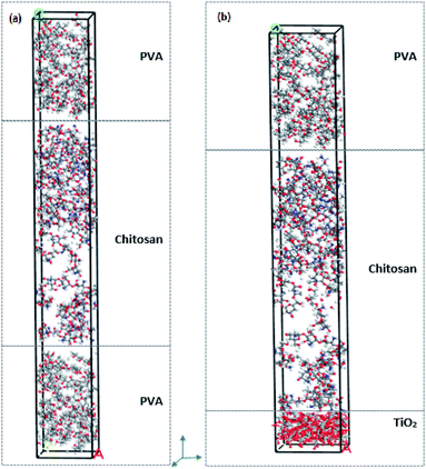
Molecular dynamics simulations were performed using Materials Studio 7. Geometry optimizations were performed for TiO2 (anatase), PVA and chitosan nanocomposites utilizing the smart minimization method in the Forcite module. The quality convergence tolerance was set to ultra-fine and the energy, force and displacement convergence tolerances were customized to 2 × 10⁻⁵ kcal mol−1, 0.001 kcal mol−1 Å−1 and 1 × 10⁻⁵ Å, respectively. The COMPASS force field was used, and the summation methods were atom-based for both the electrostatic and van der Waals forces. COMPASS is a force field for the simulation of common organic molecules, small inorganic molecules and polymers based on ab initio and empirical parametrization techniques.38,39 The “constant strain” approach40 was used to calculate the mechanical properties of the structures. A fixed strain is applied, and the structure is optimized; then the strain is increased and for each step the structure is re-optimized until the maximum strain amplitude is reached, thereby resulting in the optimum geometry for the structure. Four steps for each strain were used with a value of 0.003 for the maximum strain amplitude.40 To simulate and compare the mechanical properties of PVA–chitosan against PVA–chitosan–TiO2, the individual layers were first built and then assembled into 2 different composites. Fig. 1 shows the individual layers of Cs, PVA, and TiO2. Both the PVA and chitosan chains were first constructed from 6 monomers, and then amorphous cells of each material were constructed. A single layer of TiO2 anatase was constructed as the supercell 5 × 5 × 1 – (18.9 × 18.9 × 9.5 Å), such that its angles were fixed at 90 °C. TiO2 anatase contains 200 oxygen and 100 titanium atoms in the supercell. The amorphous cells of the PVA and chitosan were built such that they have the same base size as the TiO2 layer to enable cell matching. The two final structures to be used for comparison were then layered such that the first contains PVA–chitosan–PVA layers and the second PVA–chitosan–TiO2 layers. Fig. 2a shows the PVA–chitosan and Fig. 2b shows the PVA–chitosan–TiO2 composite. We maintained the 3-layer structure and replaced TiO2 with PVA to maintain a constant number of layers in the system.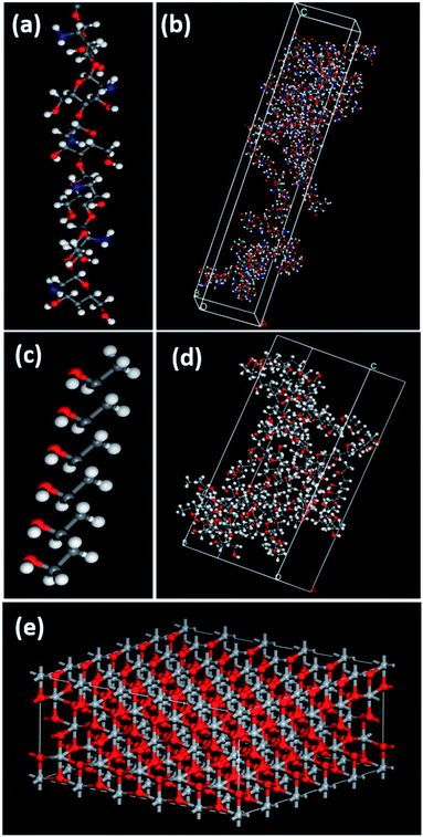 | ||
| Fig. 1 (a) Chitosan 6-monomer polymer chain, (b) amorphous cell configuration of chitosan, (c) PVA 6-monomer polymer chain, (d) amorphous cell configuration of PVA, and (e) TiO2 anatase layer. | ||
In vitro cell culture and MTT assay
The MTT assay was conducted to investigate the influence of electrospun PC and TCP nanofibrous composite materials on the cell viability. The normal human melanocyte (HFB-4) cell line was chosen as a cell model and it was cultured in T75 tissue culture flasks using Dulbecco's Modified Eagle's Medium (DMEM) with 10% Fetal Bovine Serum (FBS), 10 μg ml−1 insulin, and 1% penicillin streptomycin antibiotic. The HFB-4 cell line was incubated in a 5% CO2 incubator at 37 °C for 3 days. When the cells reached 80% confluency, the medium was replaced and trypsinization was carried out where HFB-4 cells were detached using trypsin with EDTA and centrifuged for 5 min at 60 rpm. Then, they were counted using trypan blue and a hemocytometer. The sterilization for PC and TCP nanofibrous composite materials was conducted by washing them with absolute ethanol followed by washing 2 times with PBS buffer and then UV exposure for 2 hours. Before sub-culturing the HFB-4 cells in a 96 well plate, the sterilized PC and TCP nanofibrous materials (12 mg per material) were placed where the HFB-4 cells were seeded on their surfaces at a density of 10 × 103 cells per well/100 μl, followed by adding 100 μl medium on the PC and TCP materials in the 96 well plate and incubating them for 24 hours in a 5% CO2 tissue culture incubator at 37 °C. Then, the MTT assay was conducted to ensure the existence of viable cells, excluding the unattached ones. The MTT test mainly depends on the quantitative determination of the viable cells cultured on the nanofibrous mats. The tetrazolium salt was converted to formazan dye upon reduction by dehydrogenases existing in the HFB-4 cells, which produced a purple dye soluble in the culture medium. The density of the color produced due to the formazan dye in cells is directly proportional to the number of living cells. In the MTT test, the medium was removed and the cells were washed twice using the PBS buffer solution. Each well was filled with 100 μl of MTT solution (10 mg of MTT in 20 ml medium), and then the 96 well-plate was placed back in the incubator. After that, incubating the cells with PC and TCP nanofibers and MTT solution for 4 hours at 37 °C, the MTT solution was evacuated from the wells and dimethyl sulfoxide (DMSO) was added and placed back in the incubator for 30 min. The viability of cells was checked using a microplate reader at an absorbance wavelength of 570 nm, reflecting the optical density (OD) values of the PC and TCP materials with cells and each sample was analyzed in triplicate.Results and discussion
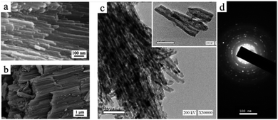
The TCP composite material is a combination of PVA/Cs polymeric nanofibers as a matrix and TiO2 NTs in the powder form as a filler. Firstly, TiO2 NT powder was successfully fabricated in the form of well aligned bundles with a smooth surface texture, a tube length of 6.23 ± 3.7 μm and an outer diameter of 42.7 ± 6.7 nm, as shown in Fig. 3a and b. The TEM images after and before annealing as well as the diffraction pattern of the NTs are shown in Fig. 3c and d, indicating a polycrystalline structure. The hollow structure of the TiO2 NTs (inset) confirms the nano-tubular structure. A comparison between the TEM images before (inset) and after annealing confirms that the nano-tubular structure was maintained even after annealing at high temperature.Moreover, to enhance the electrospinnability of Cs, it is essential to combine it with a water-soluble polymer. PVA is considered one of the best polymer candidates to blend with Cs as it was shown to increase its spinnability.41 Therefore, three different ratios of PVA![[thin space (1/6-em)]](https://www.rsc.org/images/entities/char_2009.gif) :
:![[thin space (1/6-em)]](https://www.rsc.org/images/entities/char_2009.gif) Cs (9
Cs (9![[thin space (1/6-em)]](https://www.rsc.org/images/entities/char_2009.gif) :
:![[thin space (1/6-em)]](https://www.rsc.org/images/entities/char_2009.gif) 1, 8
1, 8![[thin space (1/6-em)]](https://www.rsc.org/images/entities/char_2009.gif) :
:![[thin space (1/6-em)]](https://www.rsc.org/images/entities/char_2009.gif) 2, and 7
2, and 7![[thin space (1/6-em)]](https://www.rsc.org/images/entities/char_2009.gif) :
:![[thin space (1/6-em)]](https://www.rsc.org/images/entities/char_2009.gif) 3 w/w) were examined to identify the optimum nanofibrous morphology (bead-free nanofibers). Accordingly, several trials were conducted to investigate the best weight percentage of PVA to Cs for the TiO2 NT integration. As indicated in Fig. 1 in the ESI,† beaded nanofibers were obtained for the 9
3 w/w) were examined to identify the optimum nanofibrous morphology (bead-free nanofibers). Accordingly, several trials were conducted to investigate the best weight percentage of PVA to Cs for the TiO2 NT integration. As indicated in Fig. 1 in the ESI,† beaded nanofibers were obtained for the 9![[thin space (1/6-em)]](https://www.rsc.org/images/entities/char_2009.gif) :
:![[thin space (1/6-em)]](https://www.rsc.org/images/entities/char_2009.gif) 1 and 8
1 and 8![[thin space (1/6-em)]](https://www.rsc.org/images/entities/char_2009.gif) :
:![[thin space (1/6-em)]](https://www.rsc.org/images/entities/char_2009.gif) 2 (w/w) PVA
2 (w/w) PVA![[thin space (1/6-em)]](https://www.rsc.org/images/entities/char_2009.gif) :
:![[thin space (1/6-em)]](https://www.rsc.org/images/entities/char_2009.gif) Cs ratios, where an unstable jet was noticed during the electrospinning process. Finally, the PC solution with a PVA to Cs weight ratio of 7
Cs ratios, where an unstable jet was noticed during the electrospinning process. Finally, the PC solution with a PVA to Cs weight ratio of 7![[thin space (1/6-em)]](https://www.rsc.org/images/entities/char_2009.gif) :
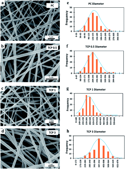
:![[thin space (1/6-em)]](https://www.rsc.org/images/entities/char_2009.gif) 3 (w/w) was selected among other counterparts to represent the plain polymeric matrix owing to its higher Cs concentration, which definitely leads to increasing the natural and bioactive constituents in the nanofibrous matrix. Additionally, it can be seen in Fig. 4a–d that randomly oriented, bead-free nanofibers with a smooth surface architecture and uniform fiber diameter were synthesized from the 7
3 (w/w) was selected among other counterparts to represent the plain polymeric matrix owing to its higher Cs concentration, which definitely leads to increasing the natural and bioactive constituents in the nanofibrous matrix. Additionally, it can be seen in Fig. 4a–d that randomly oriented, bead-free nanofibers with a smooth surface architecture and uniform fiber diameter were synthesized from the 7![[thin space (1/6-em)]](https://www.rsc.org/images/entities/char_2009.gif) :
:![[thin space (1/6-em)]](https://www.rsc.org/images/entities/char_2009.gif) 3 PVA to Cs ratio. Hence, this ratio was chosen for the incorporation of the TiO2 NTs into the PVA/Cs polymeric matrix with three TiO2 NT percentages of 0.5, 1, and 3, respectively. This morphology was maintained even after the incorporation of the TiO2 NTs due to the optimization of the applied voltage and the flow rate, as shown in Fig. 4b–d. Finally, to form the composite, TiO2 NTs were added to the polymeric solution, and then the electrospinning process was conducted for the whole TCP composite and it indicated that the TiO2 NTs were incorporated into the nanofibrous materials successfully as shown in Fig. 4e.
3 PVA to Cs ratio. Hence, this ratio was chosen for the incorporation of the TiO2 NTs into the PVA/Cs polymeric matrix with three TiO2 NT percentages of 0.5, 1, and 3, respectively. This morphology was maintained even after the incorporation of the TiO2 NTs due to the optimization of the applied voltage and the flow rate, as shown in Fig. 4b–d. Finally, to form the composite, TiO2 NTs were added to the polymeric solution, and then the electrospinning process was conducted for the whole TCP composite and it indicated that the TiO2 NTs were incorporated into the nanofibrous materials successfully as shown in Fig. 4e.
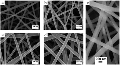 | ||
| Fig. 4 FESEM images of (a) PC, (b) TCP0.5, (c) TCP1, and (d) TCP3. (e) High resolution FESEM image confirming the uniform dispersion of TiO2 in the polymeric nanofibers. | ||
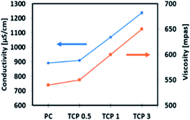
It was observed that the average diameter of the nanofibers increased upon incorporation of TiO2 NTs. As shown in Fig. 5, the histogram indicated that the formed PC, TCP0.5, TCP1, and TCP3 have an average fiber diameter of 149.4 ± 44.2, 228.8 ± 53.2, 297.3 ± 67.2, and 430.7 ± 81.7 nm, respectively. Note also that the viscosity and conductivity of the PC and TCP composite solutions were found to increase upon the addition of TiO2 NTs. As indicated in Fig. 6, the viscosity of the prepared solutions was directly proportional to the amount of TiO2 added. This increase in the solution viscosity can be attributed to the interaction of the functional groups of chitosan, PVA, and TiO2 NTs, resulting in intermolecular and intra-molecular hydrogen bonding formation between TiO2 hydroxyl groups on the surface of TiO2 NTs and the PC functional groups.42 Additionally, it was observed that the increased percentage of the TiO2 NTs was accompanied by an increase in the solution conductivity of the TCP composite nanofibers.43,44 These observations confirmed the successful enforcement of TiO2 NTs as a filler into the polymeric fibrous matrix.
After electrospinning, PC and TCP nanofibrous composite materials were cross-linked in order to enhance their mechanical properties and to improve their resistance when placed in an aqueous medium (Fig. 7a–d). The FESEM images of the cross-linked TCP1 material reveal that the morphology of the reinforcing composite materials with TiO2 NTs has stable and interconnected nanofibers compared to the cross-linked PC material. Moreover, it was also noticed from the ImageJ investigation of the FESEM images of the cross-linked PC and TCP nanofibers that the electrospun nanofiber TCP1 material exhibited the highest average pore diameter of 1970 ± 980 nm, which was higher than that of TCP0.5 (1530 ± 590 nm), TCP3 (1140 ± 340 nm), and the PC plain polymeric matrix (780 ± 440 nm), respectively. The obtained pore diameters, Fig. 7a–d, correlated with those reported by Hausner et al., indicating that porous materials facilitate the tissue integration with the materials and increased their regeneration.45
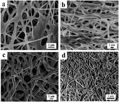 | ||
| Fig. 7 FESEM images of cross-linked (a) chitosan/PVA NFs (PC), (b) TCP1%, (c) TCP0.5%, and (d) TCP3% materials at higher magnification. | ||
Furthermore, the surface area and pore size of the PC and TCP composite materials were evaluated by the Brunauer–Emmett–Teller (BET) method from the adsorption–desorption isotherms using nitrogen gas. The results showed a significant increase in the surface area of the TCP1 nanofibrous material (83.173 m2 g−1) compared to the PC plain composite (44.936 m2 g−1) and other TCP composites, i.e., TCP0.5 (15.052 m2 g−1) and TCP3 (20.207 m2 g−1). Similarly, the TCP1 material showed the highest total pore volume (9.341 × 10⁻² cm3 g−1) while the other composites, PC, TCP0.5, and TCP3, exhibited a lower total pore volume of 6.494 × 10⁻² cm3 g−1, 2.666 × 10⁻² cm3 g−1, and 3.541 × 10⁻² cm3 g−1, respectively. These results confirmed that the incorporation of the TiO2 NTs into the polymeric nanofibrous material enhanced the surface area and the total pore volume of the mineralized composite materials.
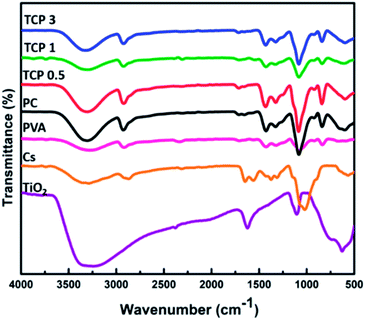
FTIR was carried out to investigate the chemical composition and the functional groups of the prepared materials. As shown in Fig. 8, the FTIR spectra showed that TiO2 nanotube peaks were observed as a broad band between 800 and 400 cm−1, which is characteristic of the Ti–O–Ti skeletal frequency region, while the peak at 590–600 cm−1 corresponds to the vibrations of Ti–O bonds in the TiO2 lattice. The vibrational peak at 1630 cm−1 is assigned to H–O–H and Ti–OH bending vibrational modes of water hydroxyl groups and Ti. The broad and intense band at 3100–3400 cm−1 can be ascribed to the stretching vibrations of the hydroxyl group –OH of TiO2 NTs. Additionally, the broad band near 3421 cm−1 is attributed not only to the presence of hydroxyl groups, but also to a strong interaction through hydrogen bonding between the hydroxyl groups on the surface.46,47 The FTIR spectra of chitosan exhibited a resonance band at 1154 cm−1 representing the saccharide structure band of chitosan, and asymmetrical stretching characteristic vibrations of C–O–C glycosidic linkages were observed at 1074 cm−1. The broad peak at 3328 cm−1 is ascribed to the amine N–H stretching vibrational group (the primary amino groups) and that at 3400 cm−1 is assigned to the OH group of the chitosan chain. The peak at 1560 cm−1 corresponds to the N–H bending of the primary amide groups, while the band at 1650 cm−1 represents the carbonyl stretching (C![[double bond, length as m-dash]](https://www.rsc.org/images/entities/char_e001.gif) O) of the secondary amide band (amide I). A very weak N–H bending of the secondary amides (amide II) appears at 1555 cm−1. Moreover, the resonance peaks at 1380 and 1074 cm−1 represent the C–H in the amide group and C– N bending vibrations, respectively.48,49 For the PVA polymer, the obtained FTIR spectra revealed that there is a characteristic band at 2923 cm−1 for the CH2 group, and the peak at 1082 cm−1 for the (C–O) group indicates the stretching vibrations that support the configuration of PVA. The resonance peak at 3307 cm−1 is assigned to the stretching –OH group and that at 835 cm−1 corresponds to the (C–C) resonance group.48 The FTIR spectra of the blend of PVA and chitosan (PC) showed an absorption band at 3350 cm−1, indicating the overlap between the absorption NH and OH stretching vibrations in chitosan and PVA. The appearance of the peak at 3322–3330 cm−1 in the mixture indicates that the OH group has shifted to a lower wavenumber in the blend samples. These results show that there are some intermolecular bands in the form of hydrogen bonds between the amino and the CH2OH group in Cs and the hydroxyl group of PVA in the blend solutions. Furthermore, the absorption peak at 1559 cm−1 in the PC blend was observed only in the PC spectra and disappeared in other different percentage TCP blends. Compared to that for pure chitosan, it is shifted to a higher wavenumber, which is due to the resonance effect between carbonyl and amino groups because of entanglement of nitrogen non-bonding electrons. An intense band is seen at 1250 cm−1 in blend samples, which is not significant in PVA and chitosan. It could be due to the C–O of the CH2OH group of chitosan which forms hydrogen bonding with the OH group of PVA. The intensity of this bond increased because of resonance; therefore, it shifted to a higher wavenumber while the 1734 cm−1 band belongs to the stretching vibrations of the ν(C
O) of the secondary amide band (amide I). A very weak N–H bending of the secondary amides (amide II) appears at 1555 cm−1. Moreover, the resonance peaks at 1380 and 1074 cm−1 represent the C–H in the amide group and C– N bending vibrations, respectively.48,49 For the PVA polymer, the obtained FTIR spectra revealed that there is a characteristic band at 2923 cm−1 for the CH2 group, and the peak at 1082 cm−1 for the (C–O) group indicates the stretching vibrations that support the configuration of PVA. The resonance peak at 3307 cm−1 is assigned to the stretching –OH group and that at 835 cm−1 corresponds to the (C–C) resonance group.48 The FTIR spectra of the blend of PVA and chitosan (PC) showed an absorption band at 3350 cm−1, indicating the overlap between the absorption NH and OH stretching vibrations in chitosan and PVA. The appearance of the peak at 3322–3330 cm−1 in the mixture indicates that the OH group has shifted to a lower wavenumber in the blend samples. These results show that there are some intermolecular bands in the form of hydrogen bonds between the amino and the CH2OH group in Cs and the hydroxyl group of PVA in the blend solutions. Furthermore, the absorption peak at 1559 cm−1 in the PC blend was observed only in the PC spectra and disappeared in other different percentage TCP blends. Compared to that for pure chitosan, it is shifted to a higher wavenumber, which is due to the resonance effect between carbonyl and amino groups because of entanglement of nitrogen non-bonding electrons. An intense band is seen at 1250 cm−1 in blend samples, which is not significant in PVA and chitosan. It could be due to the C–O of the CH2OH group of chitosan which forms hydrogen bonding with the OH group of PVA. The intensity of this bond increased because of resonance; therefore, it shifted to a higher wavenumber while the 1734 cm−1 band belongs to the stretching vibrations of the ν(C![[double bond, length as m-dash]](https://www.rsc.org/images/entities/char_e001.gif) O) groups, which correspond to the remaining acetate group.50,51 As shown in Fig. 8, the TCP0.5, TCP1, and TCP3 blends showed a peak at 470 cm−1 shifting to a lower wavenumber with the increasing quantity of TiO2 nanotubes in the polymeric blend.
O) groups, which correspond to the remaining acetate group.50,51 As shown in Fig. 8, the TCP0.5, TCP1, and TCP3 blends showed a peak at 470 cm−1 shifting to a lower wavenumber with the increasing quantity of TiO2 nanotubes in the polymeric blend.
To investigate the structural and the vibrational properties of the PC and TCP materials, Raman spectroscopy was used as the Raman signals are very sensitive to the crystal structure and lattice vibrational modes. In Fig. 9a, the Raman spectral shifts indicate that the tetragonal anatase phase of TiO2 with space group D194h (I41/amd) has six Raman active modes: 3 Eg (ν1, ν5, and ν6) at 144, 197 and 639![[thin space (1/6-em)]](https://www.rsc.org/images/entities/char_2009.gif) cm−1
cm−1![[thin space (1/6-em)]](https://www.rsc.org/images/entities/char_2009.gif) +
+![[thin space (1/6-em)]](https://www.rsc.org/images/entities/char_2009.gif) 2 B1g (ν2 and ν4) at 399 and 519
2 B1g (ν2 and ν4) at 399 and 519![[thin space (1/6-em)]](https://www.rsc.org/images/entities/char_2009.gif) cm−1
cm−1![[thin space (1/6-em)]](https://www.rsc.org/images/entities/char_2009.gif) +
+ ![[thin space (1/6-em)]](https://www.rsc.org/images/entities/char_2009.gif) A1g (ν4) at 513
A1g (ν4) at 513![[thin space (1/6-em)]](https://www.rsc.org/images/entities/char_2009.gif) cm−1. Four Raman-active modes were observed as 1 Eg (145 cm−1), 2 B1g (399 and 519 cm−1) and 1 Eg (639 cm−1), confirming the presence of TiO2 in the form of anatase. The intense, low-wavenumber band at 145
cm−1. Four Raman-active modes were observed as 1 Eg (145 cm−1), 2 B1g (399 and 519 cm−1) and 1 Eg (639 cm−1), confirming the presence of TiO2 in the form of anatase. The intense, low-wavenumber band at 145![[thin space (1/6-em)]](https://www.rsc.org/images/entities/char_2009.gif) cm−1 arises from the O–Ti–O bending vibrations, a characteristic feature of the anatase phase of TiO2. The shift and broadening of the observed Raman peaks can be attributed to the phonon confinement. It was observed that the blend of chitosan/PVA and TCP0.5 was not detected by the Raman technique because of the low concentration of TiO2 nanotube powder.52
cm−1 arises from the O–Ti–O bending vibrations, a characteristic feature of the anatase phase of TiO2. The shift and broadening of the observed Raman peaks can be attributed to the phonon confinement. It was observed that the blend of chitosan/PVA and TCP0.5 was not detected by the Raman technique because of the low concentration of TiO2 nanotube powder.52
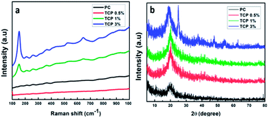 | ||
| Fig. 9 (a) Raman spectra of PC and TCP nanofibrous materials and (b) XRD spectra of PC and TCP composite materials. | ||
XRD was performed to confirm the presence of the crystalline TiO2 NTs as a nano-filler in TCP nanofibrous materials. As indicated in Fig. 9b, the XRD patterns showed characteristic diffraction peaks at 2θ of 25.01°, 37.5°, 47.7°, 54.3°, 62.6°, and 75.2°, corresponding to the (hkl) planes of (101), (004), (200), (211), (213), and (220) of the anatase phase of TiO2 incorporated into polymeric nanofibrous material PC (JCPDS card 01-075-2546), which matches with the Raman results. On the other hand, the peak appearing at 2θ of 19.18° belongs to chitosan, a polysaccharide material. The presence of titania nanotubes in the powder form, especially in the XRD pattern of the TCP3% sample, indicates the existence of the anatase phase of annealed TiO2 nanotubes, and the shift of the polysaccharide peak indicates the robust interaction between TiO2 nanotubes within the polymeric matrix. As in the Raman technique, the XRD resolution was not able to detect TCP0.5 and TCP1 because of the low quantity of TiO2 nanotubes.53,54
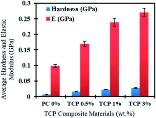
The mechanical properties of the TCP composite materials were tested and it was found that even with increasing the content of TiO2 NTs, the NTs were still evenly distributed within the polymeric matrix. Fig. 10 shows the dependence of both the hardness and Young's modulus on the added percentages of the TiO2 nanotube powder in the polymeric materials. It can clearly be observed that PC has the lowest hardness and Young's modulus compared to the TCP nanocomposite material. In addition, there is a significant increase in the hardness and Young's modulus values of the material as the content of TiO2 NT powder increases. Therefore, the increase of NT content led to enhanced resistance to deformation of the TCP material, as well as higher stiffness for the new composites compared to the PC. This increased stiffness will increase the capability of the fabricated composites to be used as efficient structural composite materials.
For further investigations of the mechanical aspects of the PC and TCP composite materials, the computational simulation results confirmed the mechanical property enhancement. The layer of TiO2 bulk anatase was modelled first and compared with experimental and DFT studies to ensure an efficient methodology to model and compare the hybrid composites. The elastic constant of TiO2 bulk anatase is presented in Table 1.
| Elastic properties | COMPASS | Reference values | Reference values | Ref. | |
|---|---|---|---|---|---|
| Stiffness coefficient, Cij (GPa) | C 11 | 332.0731 | 331.6 | 320 | 55 and 56 |
| C 12 | 106.9368 | 166.9 | 151 | 55 and 56 | |
| C 44 | 31.8996 | 48.8 | 54 | 55 and 56 | |
| Bulk modulus, B (GPa) | B R | 131.8425 | 174 | 56 | |
| B V | 144.8124 | 209–218 | 57 | ||
| B H | 138.3274 | 177 | 58 | ||
| Shear modulus, G (GPa) | G R | 56.3365 | 58 | 56 | |
| G V | 68.6855 | 90–112 | 57 | ||
| G H | 62.5110 | 64.3 | 58 | ||
| Compressibility (1/TPa) | β | 7.5848 | |||
| Young's modulus, E (GPa) | E 11 | 262.6024 | 242.37 | 38 | |
| E 22 | 203.6942 | 230–288 | 57 | ||
| E 33 | 143.9481 | 110–130 | 59 | ||
| Lame constants (GPa) | Λ | 136.5435 | |||
| M | 59.3051 |
In Table 1, it was observed from the simulation and computational calculations that the calculated values of the elastic constant are close to other experimental and theoretically derived elastic contact values for TiO2, suggesting the validity of the use of the developed model to calculate the properties of the PVA–chitosan–PVA and PVA–chitosan–TiO2 composites. In our work, TiO2 was added as nanotubes; however, we modelled them as a surface to be used as a simple proof of concept to investigate the addition of TiO2 to the PVA–chitosan mix. Table 2 compares the elastic properties of PVA–chitosan–PVA with PVA–chitosan–TiO2 to derive the effect of adding TiO2 to the PVA–chitosan mixture. The Young's modulus increased from 0.217 GPa to 16.8417 GPa; this shows that by adding TiO2 the Young's modulus increases significantly to approximately 78-fold in the x-direction and 40-fold in the z-direction. This high increase is similar to that observed by Sharma et al., where they found that a 2% addition of carbon nanofibers in a polypropylene matrix caused a 748% increase.55 The negative Young's modulus observed in the y-direction indicates a negative strain due to the atoms stretching and expanding instead of being compressed.60 Therefore, the effect of the addition of TiO2 increases its mechanical properties in 2 directions.
| Elastic properties | PVA–chitosan–PVA | PVA–chitosan–TiO2 | |
|---|---|---|---|
| Stiffness coefficient, Cij (GPa) | C 11 | 3.0740 | 14.9890 |
| C 12 | 0.7742 | −9.2535 | |
| C 44 | 0.1040 | −1.7252 | |
| Bulk modulus, B (GPa) | B R | 0.0835 | 0.7801 |
| B V | 0.8266 | −7.3690 | |
| B H | 0.4551 | −3.2945 | |
| Shear modulus, G (GPa) | G R | 0.0209 | 1.7747 |
| G V | 0.2593 | −2.0760 | |
| G H | 0.1401 | −0.1507 | |
| Compressibility, β (1/TPa) | β | 11![[thin space (1/6-em)]](https://www.rsc.org/images/entities/char_2009.gif) 976.3987 976.3987 |
1281.9162 |
| Young's modulus, E (GPa) | E 11 | 0.2170 | 16.8417 |
| E 22 | 0.4129 | −58.6396 | |
| E 33 | 0.0200 | 0.8058 | |
| Lame constants (GPa) | Λ | 1.8940 | −15.9205 |
| M | −0.0508 | 0.4079 |
The shear modulus, which measures the stiffness of the material, changes from 0.1401 to −0.1507 GPa and the bulk modulus changes from 0.4551 to −3.2945 GPa. Adding TiO2 changes the stiffness, bulk, shear and Young's modulus values to negative. In thermodynamics, a negative bulk modulus i.e. having an inverse compressibility is forbidden; however, the elasticity theory demonstrates examples of composites that possess negative bulk moduli. The spontaneous volumetric strain that occurs in the free expansion of the composite leads to a negative bulk modulus, which may occur if the transformation is subjected to a volumetric constraint.61 The motion of the interfaces between the TiO2 and polymers causes a spontaneous strain which can make the composite less stable. In our case, we believe that the inverse compressibility caused by adding TiO2 contracts the PVA–chitosan mixture, i.e. causes some atoms to be rearranged and brings them closer together (contraction), thereby making them experience a negative force. This deforms the structure in certain directions. However, this deformation and negative bulk modulus value indicate also a decreased stability of the overall structure even though the Young's modulus shows a significant increase in the composite's overall mechanical properties.
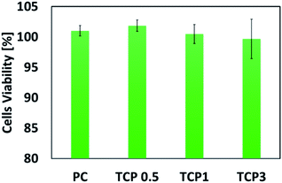
The MTT assay, which evaluates the viability of the cells through a sensitive colorimetric technique, was performed to ensure the biocompatibility of the fabricated nanomaterials for potential biomedical applications. As shown in Fig. 11, the synthesized PC and TCP nanofibrous materials indicated no cytotoxicity when the PC and TCP nanofibrous materials were compared to the negative control (not treated with materials).
Liao et al. developed electrospun nanofibrous materials from PVA–chitosan doped with multi-walled carbon nanotubes and studied the effect of the composite materials on the cell proliferation and regeneration.50 However, recently, it has been recognized that the adverse effects of multi-walled carbon nanotubes are numerous, such as their pro-inflammatory, cytotoxic, and oxidative stress influences on cells and tissues.62,63 On the other hand, Shokrgozar et al. fabricated chitosan–PVA nanofibrous embedded single walled carbon nanotube composite materials and they showed an enhancement for brain derived cells.28 Luanpitpong et al. investigated the cellular effect of carbon nanotubes and highlighted their adverse effects on the cellular behaviour of dermal and lung cells and tissues.64 Interestingly, it was observed from the MTT assessment test that there was no significant difference in the cell viability%. The TCP materials showed an increase in the cell optical density that reveals the viability of HFB-4 cells treated with the TCP materials. This can be ascribed to the high surface area to volume ratio, high total pore volume, and chemical and structural properties of the fabricated materials, especially TCP nanofibers having TiO2 incorporated into the nanofibrous mats. This can lead to a significant enhancement in the materials' biocompatibility, which makes the TCP qualify as a potential material for biomedical applications, such as tissue engineering. The observed optimum concentration of TiO2 nanotubes embedded into the nanofibrous material was 0.5% and 1% to ensure not only the safety and the biocompatibility of the mineralized composite nanofibrous materials, but also enhanced mechanical properties and higher surface area, which are necessary characteristics. Remarkably, tailoring a composite material from TiO2, chitosan, and PVA is expected to have good potential for different biological applications.
Conclusions
Novel nanofibrous composite materials were successfully fabricated using an electrospun blended polymer composite made of PVA and chitosan incorporated with TiO2 nanotube powder. It was observed that TCP composite materials are biocompatible and exhibit high surface area and high total pore volume. The obtained results of the in vitro cell viability test indicated that TCP0.5 and TCP1 were the best candidates compared to the negative control. Also, TiO2 NTs enhanced the mechanical integrity, and chemical, physical, and morphological characteristics of the fabricated composite materials. This was further confirmed via MD simulation, indicating that the inclusion of anatase TiO2 NTs improved the mechanical properties of the composite, which is consistent with the experimental findings. Therefore, the fabricated nanofibrous composite materials hold great potential for use in a plethora of biomedical applications.Conflicts of interest
There are no conflicts to declare.Acknowledgements
This work was supported by the American University in Cairo. We would like to thank Mohamed Ramadan from AUC for his support through the conducted research work.Notes and references
- D. M. Ibrahim, A. Kakarougkas and N. K. Allam, Recent advances on electrospun scaffolds as matrices for tissue-engineered heart valves, Mater. Today Chem., 2017, 5, 11–23 CrossRef.
- S. Pina, et al., Scaffolding Strategies for Tissue Engineering and Regenerative Medicine Applications, Materials, 2019, 12, 1824 CrossRef CAS PubMed.
- K. Zhang, H. Gao, R. Deng and J. Li, Emerging Applications of Nanotechnology for Controlling Cell-Surface Receptor Clustering, Angew. Chem., Int. Ed., 2019, 58, 4790–4799 CrossRef CAS PubMed.
- X. Wang, B. Ding and B. Li, Biomimetic electrospun nanofibrous structures for tissue engineering, Mater. Today, 2013, 16, 229–241 CrossRef CAS PubMed.
- N. Bhardwaj and S. C. Kundu, Electrospinning: A fascinating fiber fabrication technique, Biotechnol. Adv., 2010, 28, 325–347 CrossRef CAS PubMed.
- A. Baji, Y.-W. Mai, S.-C. Wong, M. Abtahi and P. Chen, Electrospinning of polymer nanofibers: Effects on oriented morphology, structures and tensile properties, Compos. Sci. Technol., 2010, 70, 703–718 CrossRef CAS.
- M. A. Mohamed, et al., Smart bi-metallic perovskite nanofibers as selective and reusable sensors of nano-level concentrations of non-steroidal anti-inflammatory drugs, Talanta, 2018, 185, 344–351 CrossRef CAS PubMed.
- N. A. Elsayed, S. Zada and N. K. Allam, Mineralization of electrospun gelatin/CaCO3 composites: A new approach for dental applications, Mater. Sci. Eng., C, 2019, 100, 655–664 CrossRef CAS PubMed.
- W. A. Abbas, et al., Photoactive catalysts for effective water microbial purification: Morphology-activity relationship, Environmental Nanotechnology, Monitoring & Management, 2018, 10, 87–93 Search PubMed.
- J. A. Lopes Da Silva, Functional nanofibers in food processing, Funct. Nanofibers their Appl., 2012, pp. 262–304, DOI:10.1533/9780857095640.2.262.
- S. Ibrahim, et al., Improved genistein loading and release on electrospun chitosan nanofiber blends, J. Mol. Liq., 2016, 223, 1056–1061 CrossRef CAS.
- A. P. Martínez-Camacho, et al., Antimicrobial activity of chitosan nanofibers obtained by electrospinning, Polym. Int., 2011, 60, 1663–1669 CrossRef.
- F. Gelain, et al., Transplantation of Nanostructured Composite Scaffolds Results in the Regeneration of Chronically Injured Spinal Cords, ACS Nano, 2011, 5, 227–236 CrossRef CAS PubMed.
- S. Agarwal, J. H. Wendorff and A. Greiner, Use of electrospinning technique for biomedical applications, Polymer, 2008, 49, 5603–5621 CrossRef CAS.
- Y. J. Son, W. J. Kim and H. S. Yoo, Therapeutic applications of electrospun nanofibers for drug delivery systems, Arch. Pharmacal Res., 2014, 37, 69–78 CrossRef CAS PubMed.
- H. Cao, T. Liu and S. Y. Chew, The application of nanofibrous scaffolds in neural tissue engineering, Adv. Drug Delivery Rev., 2009, 61, 1055–1064 CrossRef CAS PubMed.
- R. Nae Gyune, S. S. Choongsoo and S. Heungsoo, Current approaches to electrospun nanofibers for tissue engineering, Biomed. Mater., 2013, 8, 14102 CrossRef PubMed.
- D. Kai, S. S. Liow and X. J. Loh, Biodegradable polymers for electrospinning: Towards biomedical applications, Mater. Sci. Eng., C, 2014, 45, 659–670 CrossRef CAS PubMed.
- D. Raafat, K. Von Bargen, A. Haas and H. G. Sahl, Insights into the mode of action of chitosan as an antibacterial compound, Appl. Environ. Microbiol., 2008, 74, 3764–3773 CrossRef CAS PubMed.
- M. H. Periayah, A. S. Halim and A. Z. M. Saad, Chitosan: A Promising Marine Polysaccharide for Biomedical Research, Pharmacogn. Rev., 2016, 10, 39–42 CrossRef CAS PubMed.
- R. C. F. Cheung, T. B. Ng, J. H. Wong and W. Y. Chan, Chitosan: An Update on Potential Biomedical and Pharmaceutical Applications, Mar. Drugs, 2015, 13, 5156–5186 CrossRef CAS PubMed.
- K. Yong, L. Jeong, Y. Ok, S. Jin and W. Ho, Electrospinning of polysaccharides for regenerative medicine, Adv. Drug Delivery Rev., 2009, 61, 1020–1032 CrossRef PubMed.
- C. Saikia, P. Gogoi and T. K. Maji, Chitosan: A Promising Biopolymer in Drug Delivery Applications, J. Mol. Genet. Med., 2015, s4, 1–10 Search PubMed.
- M. Abbaspour, B. S. Makhmalzadeh, B. Rezaee and S. Shoja, Evaluation of the Antimicrobial Effect of Chitosan/Polyvinyl Alcohol Electrospun Nanofibers Containing Mafenide Acetate, Jundishapur J. Microbiol., 2015, 8, e24239 Search PubMed.
- Y. O. Kang, et al., Chitosan-coated poly(vinyl alcohol) nanofibers for wound dressings, J. Biomed. Mater. Res., Part B, 2009, 9999, 568–576 Search PubMed.
- A. Rafique, K. Mahmood Zia, M. Zuber, S. Tabasum and S. Rehman, Chitosan functionalized poly(vinyl alcohol) for prospects biomedical and industrial applications: A review, Int. J. Biol. Macromol., 2016, 87, 141–154 CrossRef CAS PubMed.
- J.-C. Park, et al., Electrospun poly(vinyl alcohol) nanofibers: effects of degree of hydrolysis and enhanced water stability, Polym. J., 2010, 42, 273–276 CrossRef CAS.
- M. A. Shokrgozar, F. Mottaghitalab, V. Mottaghitalab and M. Farokhi, Fabrication of porous chitosan/poly(vinyl alcohol) reinforced single-walled carbon nanotube nanocomposites for neural tissue engineering, J. Biomed. Nanotechnol., 2011, 7, 276–284 CrossRef CAS PubMed.
- S. Wang, Y. Zhao, M. Shen and X. Shi, Electrospun hybrid nanofibers doped with nanoparticles or nanotubes for biomedical applications, Ther. Delivery, 2012, 3, 1155–1169 CrossRef CAS PubMed.
- W. A. Abbas, et al., Recent advances in the use of TiO2 nanotube powder in biological, environmental, and energy applications, Nanoscale Adv., 2019, 1, 2801–2816 RSC.
- S. Wu, Z. Weng, X. Liu, K. W. K. Yeung and P. K. Chu, Functionalized TiO2 Based Nanomaterials for Biomedical Applications, Adv. Funct. Mater., 2014, 24, 5464–5481 CrossRef CAS.
- T. C. Lowe, et al., Titanium nanostructures for biomedical applications, Nanotechnology, 2015, 26, 062002 CrossRef PubMed.
- S. Wu, Z. Weng, X. Liu, K. W. K. Yeung and P. K. Chu, Functionalized TiO2 Based Nanomaterials for Biomedical Applications, Adv. Funct. Mater., 2014, 24, 5464–5481 CrossRef CAS.
- Y. Cheng, et al., Progress in TiO2 nanotube coatings for biomedical applications: a review, J. Mater. Chem. B, 2018, 6, 1862 RSC.
- K. Indira, U. K. Mudali and T. N. N. Rajendran, A Review on TiO2 Nanotubes: Influence of Anodization Parameters, Formation Mechanism, Properties, Corrosion Behavior, and Biomedical Applications, Journal of Bio- and Tribo-Corrosion, 2015, 1, 1–22 CrossRef.
- N. F. Fahim and T. Sekino, A Novel Method for Synthesis of Titania Nanotube Powders using Rapid Breakdown Anodization, Chem. Mater., 2009, 21, 1967–1979 CrossRef CAS.
- N. K. Allam, et al., Formation of Vertically Oriented TiO2 Nanotube Arrays using a Fluoride Free HCl Aqueous Electrolyte, J. Phys. Chem., 2007, 111, 13028–13032 CrossRef CAS PubMed.
- A. Fereidoon, S. Aleaghaee and I. Taraghi, Mechanical properties of hybrid graphene/TiO2 (rutile) nanocomposite: A molecular dynamics simulation, Comput. Mater. Sci., 2015, 102, 220–227 CrossRef CAS.
- H. Sun, COMPASS:
![[thin space (1/6-em)]](https://www.rsc.org/images/entities/char_2009.gif) An ab Initio Force-Field Optimized for Condensed-Phase Applications Overview with Details on Alkane and Benzene Compounds, J. Phys. Chem. B, 1998, 102, 7338–7364 CrossRef CAS.
An ab Initio Force-Field Optimized for Condensed-Phase Applications Overview with Details on Alkane and Benzene Compounds, J. Phys. Chem. B, 1998, 102, 7338–7364 CrossRef CAS. - M. Ismail, S. Ibrahim, A. El-Amir, A. M. EL-Rafei, N. K. Allam and A. Abdellatif, Genistein Loaded Nanofibers Protect Spinal Cord Tissue Following Experimental Injury in Rats, Biomedicines, 2018, 6, 96 CrossRef PubMed.
- H. Homayoni, S. A. H. Ravandi and M. Valizadeh, Influence of the molecular weight of chitosan on the spinnability of chitosan/poly(vinyl alcohol) blend nanofibers, J. Appl. Polym. Sci., 2009, 113, 2507–2513 CrossRef CAS.
- S. N. Alhosseini, et al., Synthesis and characterization of electrospun polyvinyl alcohol nanofibrous scaffolds modified by blending with chitosan for neural tissue engineering, Int. J. Nanomed., 2012, 7, 25–34 CAS.
- G. Zhang, et al., Ionic liquid assisted electrospun cellulose acetate fibers for aqueous removal of triclosan, Langmuir, 2015, 31, 1820–1827 CrossRef CAS PubMed.
- J.-D. Jeon, M.-J. Kim and S.-Y. Kwak, Effects of addition of TiO2 nanoparticles on mechanical properties and ionic conductivity of solvent-free polymer electrolytes based on porous P(VdF-HFP)/P(EO-EC) membranes, J. Power Sources, 2006, 162, 1304–1311 CrossRef CAS.
- T. Hausner, R. Schmidhammer, S. Zandieh, R. Hopf, A. Schultz, S. Gogolewski, H. Hertz and H. Redl, Nerve regeneration using tubular scaffolds from biodegradable polyurethane, Acta Neurochir., Suppl., 2007, 100, 69–72 CAS.
- R. Beranek and H. Kisch, Tuning the optical and photoelectrochemical properties of surface-modified TiO2, Photochem. Photobiol. Sci., 2008, 7, 40–48 RSC.
- B. Erdem, et al., XPS and FTIR Surface Characterization of TiO2 Particles Used in Polymer Encapsulation, Langmuir, 2001, 17, 2664–2669 CrossRef CAS.
- R. Sharma, et al., Electrospun chitosan–polyvinyl alcohol composite nanofibers loaded with cerium for efficient removal of arsenic from contaminated water, J. Mater. Chem. A, 2014, 2, 16669–16677 RSC.
- K. A. Gholipour, S. H. Bahrami and M. Nouri, Chitosan-poly(vinyl alcohol) blend nanofibers: Morphology, biological and antimicrobial properties, e-Polym., 2009, 9, 133 Search PubMed.
- H. Liao, et al., Improved cellular response on multiwalled carbon nanotube-incorporated electrospun polyvinyl alcohol/chitosan nanofibrous scaffolds, Colloids Surf., B, 2011, 84, 528–535 CrossRef CAS PubMed.
- M. Koosha, H. Mirzadeh, M. A. Shokrgozar and M. Farokhi, Nanoclay-reinforced electrospun chitosan/PVA nanocomposite nanofibers for biomedical applications, RSC Adv., 2015, 5, 10479–10487 RSC.
- T. Ohsaka, F. Izumi and Y. Fujiki, Raman Spectrum of Anatase, TiO2, J. Raman Spectrosc., 1978, 7, 321–324 CrossRef.
- G. L. Clark and A. F. Smith, X-ray Diffraction Studies of Chitin, Chitosan, and Derivatives, J. Phys. Chem., 1935, 40, 863–879 CrossRef.
- K. Sakurai and M. Mizusawa, X-ray Diffraction Imaging of Anatase and Rutile, Anal. Chem., 2010, 82, 3519–3522 CrossRef CAS PubMed.
- S. Sharma, R. Chandra, P. Kumar and N. Kumar, Molecular level analysis of carbon nanofiber reinforced polymer composites, J. Compos. Mater., 2016, 50, 1787–1804 CrossRef CAS.
- M. Iuga, G. Steinle-Neumann and J. Meinhardt, Ab initio simulation of elastic constants for some ceramic materials, Eur. Phys. J. B, 2007, 58, 127–133 CrossRef CAS.
- Titanium Dioxide–Titania (TiO2), https://www.azom.com/article.aspx?ArticleID=1179, accessed 6 May 2019.
- T. Mahmood, et al., Elastic, electronic and optical properties of anatase TiO2 under pressure: A DFT approach, Chin. J. Phys., 2017, 55, 1252–1263 CrossRef CAS.
- Y. Yoon and J. Park, The effects of nanostructures on the mechanical and tribological properties of TiO2 nanotubes, Nanotechnology, 2018, 29, 165705 CrossRef PubMed.
- H. Zhang and J. F. Banfield, Structural Characteristics and Mechanical and Thermodynamic Properties of Nanocrystalline TiO2, Chem. Rev., 2014, 114, 9613–9644 CrossRef CAS PubMed.
- T. M. Jaglinski and R. S. Lakes, Negative stiffness and negative Poisson's ratio in materials which undergo a phase transformation, Adaptive Structures: Engineering Applications, 2007, DOI:10.1002/9780470512067.ch8.
- R. Girardello, N. Baranzini, G. Tettamanti, M. de Eguileor and A. Grimaldi, Cellular responses induced by multi-walled carbon nanotubes: in vivo and in vitro studies on the medicinal leech macrophages, Sci. Rep., 2017, 7, 8871 CrossRef PubMed.
- L. Tabet, et al., Adverse effects of industrial multiwalled carbon nanotubes on human pulmonary cells, J. Toxicol. Environ. Health, Part A, 2009, 72, 60–73 CrossRef CAS PubMed.
- S. Luanpitpong, L. Wang and Y. Rojanasakul, The effects of carbon nanotubes on lung and dermal cellular behaviors, Nanomedicine, 2014, 9, 895–912 CrossRef CAS PubMed.
Footnote |
| † Electronic supplementary information (ESI) available. See DOI: 10.1039/d0na00042f |
| This journal is © The Royal Society of Chemistry 2020 |

