
 Open Access Article
 This Open Access Article is licensed under a Creative Commons Attribution-Non Commercial 3.0 Unported Licence
Electrochemical performance of a self-assembled two-dimensional heterostructure of rGO/MoS2/h-BN†
Ashwini P.
Alegaonkar
a,
Prashant S.
Alegaonkar
*b and
Satish K.
Pardeshi
 *a
*a
aDepartment of Chemistry, Savitribai Phule Pune University (Formerly University of Pune), Ganeshkhind, Pune 411 007, MS, India. E-mail: skpar@chem.unipune.ac.in
bDepartment of Physics, School of Basic and Applied Sciences, Central University of Punjab, City Campus, Mansa Road, Bathinda 151 001, Punjab, India. E-mail: prashant.alegaonkar@gmail.com
First published on 20th February 2020
Abstract
We report the preparation and electrochemical performance evaluation of a two-dimensional (2D) self-assembled heterostructure of graphene oxide (rGO), molybdenum disulphide (MoS2), and hexagonal boron nitride (h-BN). In the present study, the rGO–MoS2–h-BN (GMH) multi-layered GMH heterostructure is fabricated via an in situ chemical route. Based on material analysis, the composite consists of bond conformations of C–B–C, Mo–S, C–N, B–N, and Mo–C, indicating the layered stacks of rGO/h-BN/MoS2. In electrochemical analysis, the composite showed superior performance in the aqueous medium of cobalt sulphate (CoSO4) over other samples. CV measurements, performed over the range 10 to 100 mV s−1, showed a change in specific capacitance (Csp) from 800 to 100 F g−1. GMH showed almost no degradation up to 20![[thin space (1/6-em)]](https://www.rsc.org/images/entities/char_2009.gif) 000 cycles @ 100 mV s−1. The calculated Csp, energy density (ED), and power density (PD) are discussed in light of Nyquist, Bode, and Ragone analysis. An equivalent circuit is simulated for the cell and its discrete electronic components are discussed. Due to its larger effective electron diffusion length > 1000 μm, broadly, the composite showed battery-like characteristics, as supported by radical paramagnetic resonance and transport response studies. The symmetric electrodes prepared in one step are facile to fabricate, easy to integrate and involve no pre or post-treatment. They possess superior flat cell character, are cost effective, and are favourable towards practicality at an industrial scale, as demonstrated on the laboratory bench. The details are presented.
000 cycles @ 100 mV s−1. The calculated Csp, energy density (ED), and power density (PD) are discussed in light of Nyquist, Bode, and Ragone analysis. An equivalent circuit is simulated for the cell and its discrete electronic components are discussed. Due to its larger effective electron diffusion length > 1000 μm, broadly, the composite showed battery-like characteristics, as supported by radical paramagnetic resonance and transport response studies. The symmetric electrodes prepared in one step are facile to fabricate, easy to integrate and involve no pre or post-treatment. They possess superior flat cell character, are cost effective, and are favourable towards practicality at an industrial scale, as demonstrated on the laboratory bench. The details are presented.
1. Introduction
Today's industrial market requires compact instruments with high energy storage devices, and the demand is ever-increasing for these power backup systems. The widespread usage of lithium-ion batteries is mainly due to advances in this technology. Rechargeable lithium-ion batteries have already acquired a milestone position as dominant energy sources; they power almost all forms of consumer electronics, including electric vehicles, strategic systems, and digital home appliances. This is due to their capability to provide high energy density (ED). In spite of their extensive use, lithium-ion batteries possess several drawbacks, such as poor cycle life, low power performance, fire risk, carcinogenic waste, aging effects, and high cost.1 In recent years, supercapacitors have been considered as alternatives to lithium-ion batteries due to their safety aspects, their capability to deliver ∼10 times more power density (PD) than batteries, and their stability over millions of charge/discharge cycles.2,3 Further, current batteries are not sufficient to enable cars to drive distances comparable to those of combustion energy-driven vehicles. In order to commercially realise the technology of supercapacitors, enormous amounts of research endeavours are being performed to improve their technical specifications, such as ED, PD, and life cycle. A considerable amount of work has been carried out to fabricate electrode materials, select appropriate electrolyte environments, etc. Several two-dimensional (2D) materials, such as graphene, molybdenum disulphide, hexagonal boron nitride, transition metal dichalcogenides (TMDCs), g-C3N4, phosphorene layered double hydroxides and MXenes,4–8 are desirable for energy storage applications due to their outstanding structural-property relationships. In addition to graphene, transition metal dichalcogenides (TMD), post-graphene contenders, and transition metal oxides (TMO)/hydroxides (TMH) are considered as potential candidates. The structures of TMO and TMH in the form of films, flakes, platelets, petals, belts, etc., significantly alter the inherent properties of supercapacitors, showing excellent ED. This is a huge class, among which we have specifically chosen reduced graphene oxide (rGO), MoS2 and h-BN in the form of a blend to investigate their electrochemical performance. Basically, the use of carbon compounds in energy storage devices has its own advantages in the form of superior performance, high surface area, low cost, affordability of large scale applications and facile preparation protocols. There are a number of reports on the use of nanocarbons such as rGO, single-walled carbon nanotubes (CNTs), CNTs/polymers, rGO–TMO, activated carbon, and multi-walled CNTs to achieve superior specific capacitance (Csp, in F g−1). Particularly, rGO showed Csp ∼ 200 @ 1200 cycles in the electrolyte KOH,9,10 >300 @ 1000 cycles in PVA,11 and ∼600 @ 1000 in H2SO4.12Similarly, the MoS2 layers alone show the ability to store electrostatic charge by an electrode double layer capacitance (ELDC) mechanism. However, they suffer from inferior electrochemical performance in terms of poor cyclic life, inherently low charge transport, large volume changes during cycling, and restacking,13,14 yielding Csp ∼ 100 F g−1 @ 1 mV s−1 (scan rate).15 In order to overcome this issue, MoS2 has been mixed, wrapped or deposited with highly conductive/electroactive materials such as carbonaceous materials or conducting polymers using various top-down/bottom-up synthetic methods as well as combinatorial approaches.16–25
Pristine h-BN, being an electrical insulator, is not suitable for this branch of application. However, due to its structural similarity with graphene and comparatively weak van der Waals forces, it offers strong ionic bonds and is expected to provide superior Csp if combined with graphene and MoS2.26
There are many reports of binary composites. Further, binary composites of rGO are reported to show excellent electrochemical properties. In the work carried out by Jiao et al., a MoS2/rGO composite prepared via hydrothermal delivered excellent electrochemical properties with almost 95% capacitance retention.27 In other work reported by Zhao et al., MoS2/rGO showed superior electrochemical properties with a specific capacitance of more than 1200 F g−1.28 A layer-controlled MoS2/graphene aerogel composite was also reported to show reversible capacity, with a specific capacitance of more than 1000 mA g−1 at a current density of 100 mA g−1.29
The focus of our current work is to investigate the electrochemical parameters of a rGO/h-BN/MoS2 heterostructure. This self-assembled composite is prepared by facile addition of equal volume ratios. The blend showed successful formation of the composite 2D material. The electrochemical properties were studied to realize the effects of the blend of all the 2D materials; it showed a Csp > 650 F g−1 (current density) with a highest ED > 90+ W h kg−1 and a PD of 1700 W kg−1. The combination studied herein has not been reported to date for electrochemical applications. The details are presented.
2. Experimental section
2.1 Reagents
Natural graphite flakes were purchased from Sigma Aldrich. All other reagents are analytical grade chemicals.2.2 Preparation of the rGO/MoS2/h-BN multi-layered material: GMH-composite
Initially, graphene oxide (GO) was prepared from a natural graphite precursor by a modified Hummers route.30 GO was washed with DI water several times in order to obtain GO free from acidic moieties. Hexagonal boron nitride (h-BN) was prepared according to the protocols given in ref. 31. For this, around 3 g of boric acid (HBO3) and approximately 9 g of urea were mixed in acetone, and the solution was stirred for approximately 15 m. Following this, the acetone was allowed to evaporate under natural conditions, and the obtained powder was heated for ∼700 °C for 5 h under nitrogen atmosphere. In a round bottom flask, subsequently, GO (500 mg), h-BN (500 mg), ammonium molybdate ((NH4)6Mo7O24–4H2O, (1.25 g)) and thiourea (CH4–NH2S, 2.31 g) were added to DI water.32 To the reaction mixture, hydrazine hydrate (10 ml) was added, and the entire system was maintained with heating at ∼80 °C in an oil bath for about 4 h. After this, the system was allowed to cool to room temperature. During the synthesis of h-BN, the small amount of B2O3 formed may be reduced in the presence of hydrazine hydrate. Moreover, we prepared MoS2in situ during the reduction process of GO. The water was separated using vacuum filtration and the black residue was washed using hot DI water and ethanol, sequentially. The residue was sonicated further for about 4 h to exfoliate the interlayers. Finally, the product was assumed to be multi-layered rGO/MoS2/h-BN and termed GMH-composite. It was further characterized for its structure–property relationships and by electrochemical application studies.2.3 Characterization of GMH-composite
Electron spectroscopy for chemical analysis (ESCA) measurements were performed using an Omicron ESCA probe (Omicron Nanotechnology). X-ray powder diffraction studies were carried out using a Rigaku instrument with Cu Kα radiation (1.5406 Å) over the 2θ range of 10–90° @ a scanning rate of 2° m−1. FTIR measurements were performed from 400 to 4000 cm−1 using a Bruker Tensor 37, and Raman measurements were performed over 200 to 3500 cm−1 using a LABRAM HR 800 (@ λ ∼ 533 nm). Nanostructure imaging was carried out by field emission scanning microscopy (FSEM, S-4700), high resolution transmission electron microscopy (HRTEM, JEOL-2100F) and energy dispersive X-ray (EDAX) elemental mapping. ESR measurements were performed at 9.4 GHz (X-band) with a microwave input of 950 μW.2.4. Electrochemical measurements
The electrochemical performance of GMH was determined using cyclic voltammetry (CV) and galvanostatic charge–discharge (CD) studies. In order to understand the various impedance factors experienced by the electrode/electrolyte interface and the charge transfer process, electrochemical impedance spectroscopy measurements (EIS, Ivium Technology, Vertex) @ 0.1 to 106 Hz were performed. All studies were carried out using an Autolab workstation (PGSTAT 30, Eco Chemie) at room temperature. Electrode preparation was performed as per the protocols given inref. 33. The composite of GMH and polyvinylidene fluoride (PVDF) was mixed with the solvent N-methyl-2-pyrrolidone (NMP) in a ratio of 9:1, and the slurry was dropped onto glassy carbon electrode using the drop cast technique. The electrode was dried to perform CV, CD and EIS measurements. In the CV measurements, the three electrodes used were platinum wire as a counter electrode, Ag/AgCl as a reference electrode, and CNS as a working electrode. The CV curves were obtained in a potential window of 0.2 to 0.8 V @ scan rates of 10, 50, 100, 300, 500 and 1000 mV s−1. In a similar fashion, two-electrode CV measurements were performed in addition to constant CD measurements @ 1.0 to 3.5 A g−1. The electrolytes used were H2SO4 (1 M), Na2SO4 (1 M), and Co2SO4 (1 M). The cyclic stability of the cell was investigated up to 20000 cycles @ 1 A g−1.
3. Results and discussion
3.1 Structure–property relationship: pre-analysis of GMH-composite
Fig. 1(a) shows the recorded FTIR spectra of MoS2, rGO, h-BN, and GMH-composite. For h-BN, a typically broad B–N peak appeared at ∼1400 cm−1, displaying in-plane B–N–B stretching (str.), whereas the peak at ∼750 shows out-of-plane B–N–B stretching. For rGO, the peaks that appeared at 1300 to 1500 cm−1 are assigned to C–C str. and C–H bending, whereas the peak at ∼665 cm−1 shows C–H out-of-plane vibrations. In MoS2, the peak at ∼615 is due to the presence of Mo–S str. In addition, the profile shows small peaks at ∼950 and 850 cm−1 due to Mo–O str., as shown in the inset to the corresponding zoomed region in plot (c). These peaks also shifted to lower wavelengths, supporting the formation of the composite. Their presence may be due to atmospheric handling of the material. However, the IR profile of GMH-composite shows the features of individual components, such as the peak at ∼1600 due to C![[double bond, length as m-dash]](https://www.rsc.org/images/entities/char_e001.gif) C str. In the composites, the peaks associated with B–N, C–C, and C–H appear to overlap due to their similar vibration frequencies; hence, the bands appearing at 1300 to 1500 cm−1 are attributed to their presence. A sharp peak observed at 900 cm−1 is assigned to Mo–O, at 700 cm−1 to B–N–B, and at ∼630 cm−1 to Mo–S stretching vibrations. Primarily, the prepared composite shows the vibration features of individual MoS2, MoO3, h-BN, and reduced graphene oxide 2D layers. Further, the plot (b) is the recorded XRD pattern of the composite obtained on calcination at 350 °C; it shows distinct diffraction peaks associated with rGO, h-BN and MoS2 in the blend. The individual XRD patterns are provided in the ESI.† For MoS2, namely, peaks 1–5 match with JCPDS card no. 37-1492. The values for 2θ are ∼12° (1), 33° (2), 33° (3), 39° (4), and 42° (5), with corresponding Miller planes of (0 0 2), (1 0 0), (1 0 3), (1 0 5) and (1 1 0). The intensity of these lines is observed to be low due to exfoliation and intercalation within the layers of rGO and h-BN and is indicative of lowering of the number of layers.34 Moreover, h-BN and rGO have very similar crystal structures, with a very small lattice constant mismatch of ∼2%. Therefore, the main peaks have similar positions and intensities. For rGO, they are indicated by number 6. The broad peak shifted to sharp crystalline at 2θ = 23.34° is indicative of rGO, corresponding to a d spacing of 0.326 nm. During the formation of the heterostructure, the d spacing of rGO in the blend is reduced by almost half. The lattice structure is significantly different from that of the pristine graphite flakes; this shows substantial exfoliation of the conjugated 2D carbon layers. For h-BN, the XRD pattern matches JCPDs card number 73-2095, as shown in Fig. 7–10. The corresponding matching planes are (1 0 0), (1 0 1), (0 0 4), and (1 1 0), as shown by the numbers.35 To summarize, the composite of GMH shows the presence of the multi-layered heterostructure h-BN/MoS2/rGO, as desired for electrochemical applications. Plot (c) shows the Raman spectrum recorded at an excitation wavelength of 533 nm for the composite. The inset shows the magnified region of 240–450 cm−1, in which 4 peaks were clearly identified for MoS2. The D band at 1340 cm−1 has a higher intensity than the G band at 1590 cm−1, which indicates the presence of impurities induced due to MoS2 and h-BN. In addition, 2D doublets were registered in the blend at ∼2700 cm−1. h-BN shows a characteristic peak at 1370 cm−1, which is due to the E2g phonon mode and is similar to the mode associated with the D band in graphene.36 In the composite samples, their presence is not observed separately due to mutual overlap; however, this resulted in a mixed band at a somewhat lower wavelength of 1340 cm−1. The position of the D band also shifted to a lower wavelength.37 Characteristic bands of MoS2 appeared at 280, 335, 370, and 418 cm−1. The bands at 370 and 418 cm−1 are attributed, respectively, to E12g and A1g modes, while the major characteristic peaks at 280 and 335 cm−1 belong to E1g and longitudinal acoustic phonon modes, respectively. These three peaks are associated with the 1T phase of MoS2. This indicates that during composite formation, 1T phase is formed; this may improve the structural stability of MoS2.38,39
C str. In the composites, the peaks associated with B–N, C–C, and C–H appear to overlap due to their similar vibration frequencies; hence, the bands appearing at 1300 to 1500 cm−1 are attributed to their presence. A sharp peak observed at 900 cm−1 is assigned to Mo–O, at 700 cm−1 to B–N–B, and at ∼630 cm−1 to Mo–S stretching vibrations. Primarily, the prepared composite shows the vibration features of individual MoS2, MoO3, h-BN, and reduced graphene oxide 2D layers. Further, the plot (b) is the recorded XRD pattern of the composite obtained on calcination at 350 °C; it shows distinct diffraction peaks associated with rGO, h-BN and MoS2 in the blend. The individual XRD patterns are provided in the ESI.† For MoS2, namely, peaks 1–5 match with JCPDS card no. 37-1492. The values for 2θ are ∼12° (1), 33° (2), 33° (3), 39° (4), and 42° (5), with corresponding Miller planes of (0 0 2), (1 0 0), (1 0 3), (1 0 5) and (1 1 0). The intensity of these lines is observed to be low due to exfoliation and intercalation within the layers of rGO and h-BN and is indicative of lowering of the number of layers.34 Moreover, h-BN and rGO have very similar crystal structures, with a very small lattice constant mismatch of ∼2%. Therefore, the main peaks have similar positions and intensities. For rGO, they are indicated by number 6. The broad peak shifted to sharp crystalline at 2θ = 23.34° is indicative of rGO, corresponding to a d spacing of 0.326 nm. During the formation of the heterostructure, the d spacing of rGO in the blend is reduced by almost half. The lattice structure is significantly different from that of the pristine graphite flakes; this shows substantial exfoliation of the conjugated 2D carbon layers. For h-BN, the XRD pattern matches JCPDs card number 73-2095, as shown in Fig. 7–10. The corresponding matching planes are (1 0 0), (1 0 1), (0 0 4), and (1 1 0), as shown by the numbers.35 To summarize, the composite of GMH shows the presence of the multi-layered heterostructure h-BN/MoS2/rGO, as desired for electrochemical applications. Plot (c) shows the Raman spectrum recorded at an excitation wavelength of 533 nm for the composite. The inset shows the magnified region of 240–450 cm−1, in which 4 peaks were clearly identified for MoS2. The D band at 1340 cm−1 has a higher intensity than the G band at 1590 cm−1, which indicates the presence of impurities induced due to MoS2 and h-BN. In addition, 2D doublets were registered in the blend at ∼2700 cm−1. h-BN shows a characteristic peak at 1370 cm−1, which is due to the E2g phonon mode and is similar to the mode associated with the D band in graphene.36 In the composite samples, their presence is not observed separately due to mutual overlap; however, this resulted in a mixed band at a somewhat lower wavelength of 1340 cm−1. The position of the D band also shifted to a lower wavelength.37 Characteristic bands of MoS2 appeared at 280, 335, 370, and 418 cm−1. The bands at 370 and 418 cm−1 are attributed, respectively, to E12g and A1g modes, while the major characteristic peaks at 280 and 335 cm−1 belong to E1g and longitudinal acoustic phonon modes, respectively. These three peaks are associated with the 1T phase of MoS2. This indicates that during composite formation, 1T phase is formed; this may improve the structural stability of MoS2.38,39
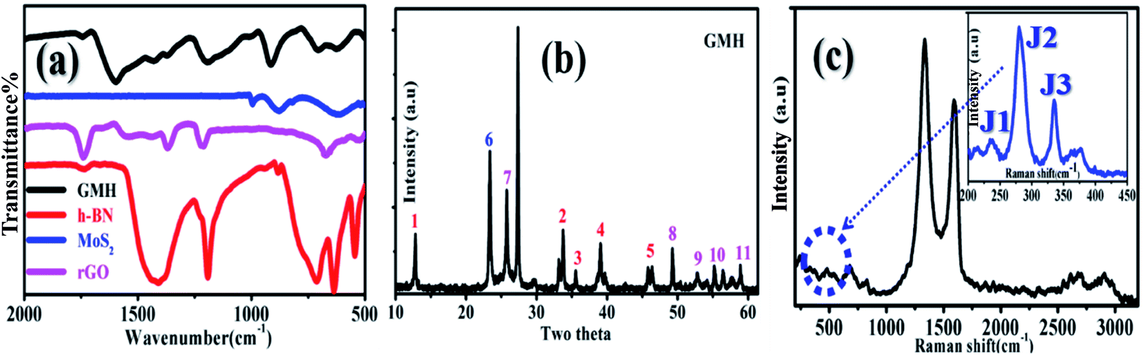 | ||
| Fig. 1 (a) FTIR spectra of the individual components and GMH-composite, (b) XRD pattern of the composite (the coloured numbers show the characteristic peaks of the respective components), and (c) Raman spectra recorded at 533 nm for the composite (the zoomed portion of the dotted circle connects the typical J1, J2 and J3 peaks; the inset shows the characteristic Raman features for 1T-MoS2). | ||
In order to understand the surface chemical composition and the valence state of the GMH blend, XPS analysis was carried out. Fig. 2 shows the corresponding spectra. The inset of plot (a) shows a survey spectrum indicating the coexistence of elements such as B, S, Mo, C, N, and O in GMH. Further, the composition of MoS2 in GMH was confirmed by the high resolution of the MoS2 spectrum, shown in plot (b). The Mo-3d peak can be deconvoluted to four peak fits at binding energies of 226.5, 230.4, 232.8, and 235.2 eV. The peak at 230.4 eV is assigned to Mo (+4) 3d5/2 and that at 232.8 eV is assigned to 3d3/2, with a spin–orbit coupling separation of nearly 2.4 eV. The shift of these additional peaks suggests that they arise from 1T phase. This can be identified to be metallic 1T phase partially mixed with oxidized MoS2, which is consistent with the Raman analysis.39 The peak at 235.05 is assigned to the respective Mo (+6) 3d electronic shell. The emergence of this peak may be due to the exposure of MoS2 to air, showing the presence of MoO3, or may be due to incomplete reduction of Mo (+6).27 In addition, the peak at a binding energy of 226.4 eV corresponds to S 2s of MoS2 and also shows a resemblance to the spectral region of S-2p (plot (f)). For sulphur, the peaks at 161.8 and 163.04 are assigned to Mo–S bonding, with spin–orbit coupling of ∼1.24 eV. Moreover, in (f), the spectrum shows that the binding energy of S-2p3/2 is 161.9, which corresponds to a charge state of S of −2 in MoS2. Further, the peak at 164.3 corresponds to C–S bonding, whereas the peak at 168.5 corresponds to carbon-sulfonate bonding. Meanwhile, in plot (e), O-1s is deconvoluted to three components at 532.2, 531.04, and 530.3 eV; these broadly correspond to C–O and M–O bonding. In plot (a), the C-1s envelope is fitted to three peaks. Particularly, the peak at 284.5 eV appears to be broad and has a asymmetric tail towards the higher binding energy side, which shows a high concentration of sp2 content in rGO. Meanwhile, other peaks at 285.6 and 288.15 eV with a difference of 1–2 eV show the presence of an sp3 fraction emerging from the C–O and CO components, respectively. In plot (d), the N-1s spectrum is fitted for three components, in which the main broad peak at 396.5 is attributed to N–B bonding in h-BN; meanwhile, the other peak centred at ∼400 is attributed to the presence of N–H bonds or amide groups,40 and the peak at ∼401 shows C–N bonds. In plot (c), the deconvoluted B-1s spectrum indicates the existence of sp2-like phase in B–N due to peaks appearing at ∼193 and ∼187 eV. These show the substitution of boron sites that exist in the rGO network of the GMH composite.41,42
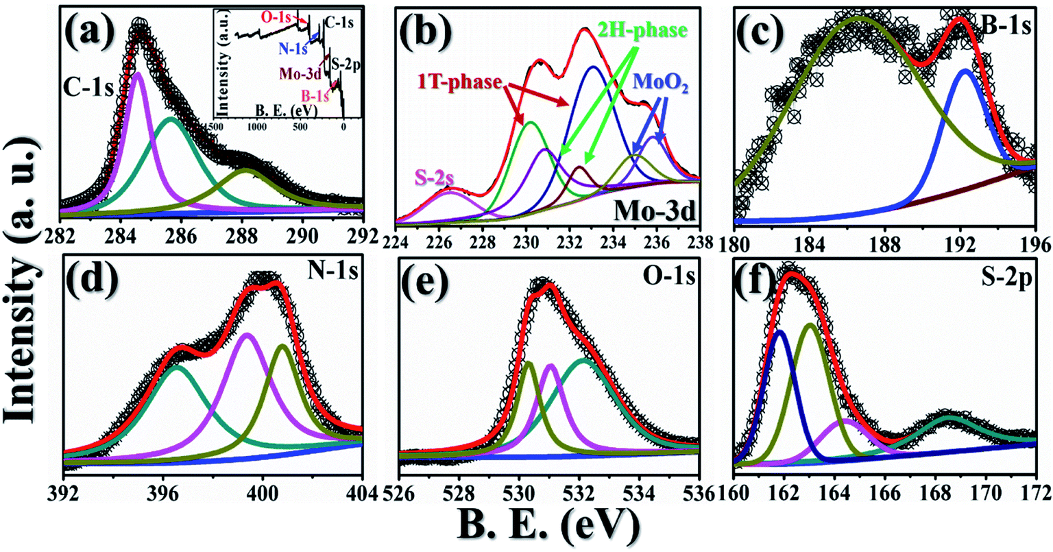 | ||
| Fig. 2 Recorded XPS spectra for GMH-composite: (a) C-1s (inset: elemental survey scan), (b) Mo-3d (indicating 1T, 2H and oxide states), (c) B-1s, (d) N-1s, (e) O-1s, and (f) S-2p. | ||
In the analysis of GMH-composite, broadly, the excess oxygen containing groups are significantly reduced, and only a small amount of oxygen is observed to reside in the 2D multilayers. From the rGO, h-BN and MoS2 sheets, unwanted traces of hydroxide/epoxide, B2O3, and MoO3, respectively, are removed due to the action of hydrazine hydrate as a reducing agent. The blend is found to be rich in C–B–C, Mo–S, C–N, B–N, Mo–C, etc.; this indicates that molecular bonding enabled the formation of composite layers.
3.2 Morphological analysis of GMH-composite
Electron microscopy imaging analysis was carried out in order to investigate the morphology of GMH-composite. Fig. 3 shows typical FESEM images of rGO, MoS2, h-BN and GMH, and the EDX spectrum of GMH-composite. The FESEM image of rGO in Fig. 3(a) shows a smooth, homogeneous surface with typical wrinkles of rGO sheets that cause sheet folding. The corrugation and scrolling represent the intrinsic nature of graphene because the 2D membrane structure becomes thermodynamically stable via blending with the corrugation and scrolling.34,36Fig. 3(b) shows coalesced plate-like MoS2 particles. It can be seen that these microspheres are composed of stacked nanosheets assembled into uniform nanospheres. These nanosphere-like sheets are loosely intercrossed and contain void spaces between them. Part (c) shows an FESEM image of h-BN, indicating sharp edges and a flat, smooth surface. However, the FESEM images of GMH show an entirely different morphology. It is shown in part (d) that layered lump-like structures can be seen. Compact packing can be observed, and the layers of rGO appear to be broken down into small layers. For the GMH micrographs of cross section part (e) and part (f), it can be seen that the 2D planes are tightly stacked and the layered structure is well preserved, with h-BN and MoS2 planes sandwiched in between the layers. The tightly packed layered structure plays a key role in the efficient charge transfer as well as the storing between three nanosheets.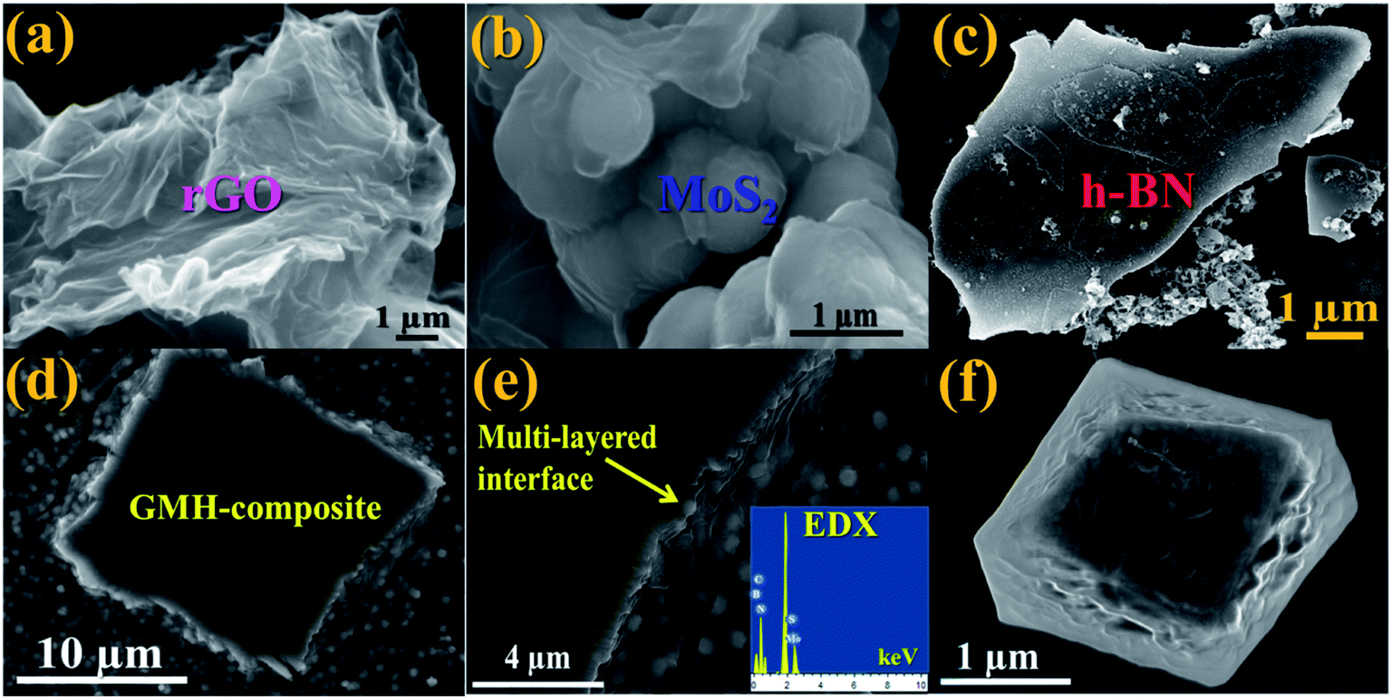 | ||
| Fig. 3 Typical FESEM images. The upper panel shows individual 2D layers of (a) rGO, (b) MoS2, and (c) h-BN. Lower panel: (d) GMH-composite, (e) sandwiched layers (inset: EDAX spectrum revealing the elemental composition), (f) a smaller block of the blend. | ||
Fig. 4(a) shows a typical TEM image of rGO, indicating well-defined stacked graphitic planes, and the respective inset displays higher resolution imaging with lattice fringes. This indicates notable crystallization of the sheets. Image (b) shows two layers of MoS2; it appears that due to stacking faults, the crystallinity is somewhat lost. In (c), crystalline h-BN can be seen, with some structural defects indicated by yellow double circles. These defects can be attributed to the presence of B2O3. They can be passivated by adding more hydrazine hydrate, as discussed previously. The corresponding inset shows the SAED pattern, which confirms the crystallinity of h-BN. Image (d) shows stacked compact layers of rGO, MoS2 and h-BN, and the SAED pattern shows the amorphous nature of the blend. The supercapacitor performance of GMH-composite was investigated by cyclic voltammetry (CV) studies.
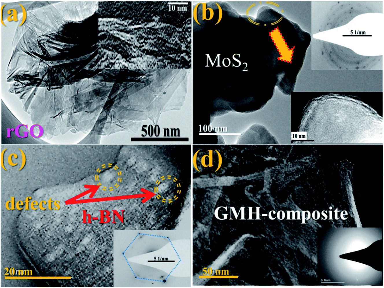 | ||
| Fig. 4 Typical HRTEM images of (a) rGO (inset: higher resolution of layers), (b) MoS2 (inset: higher resolution and SAED pattern), (c) h-BN arrows and double circles showing defects (inset corresponding SAED), and (d) GMH-composite with SAED. | ||
3.4 Electrochemical studies
In Fig. 5, plot (a) shows three electrode CV curves obtained for GMH-composite in different aqueous electrolytes at a scan rate of 10 mV s−1. The values of the specific capacitance, Csp, measured in F g−1, were recorded to be 302.67, 564.18, and 745.18 for electrolytes H2SO4, Na2SO4, and CoSO4, respectively. These were calculated using the relation . The magnitude of Csp in H2SO4 electrolyte is low, and the shape of the CV curve is somewhat distorted. This may be due to the corrosive nature of acid towards the metallic species present in the composite. Acidic and basic electrolytes can act as current collectors and provide connexions. In order to overcome these technical drawbacks, they should be avoided.39 Neutral electrolytes such as Na2SO4 and CoSO4 showed symmetric current potential characteristics, indicating ideal capacitive behaviour. In general, the process of oxidation and reduction during cycling depends on the physical parameters of the cations, such as charge, charge density and size.40 The highest value of Csp was obtained for CoSO4, which was used for further analysis. This is attributed to the smaller cationic radius of Co2+ ion (0.72 Å) than of Na+ (0.99 Å). Plot (b) presents profiles (three electrodes) at various scan rates from 10 to 100 mV s−1 in CoSO4 electrolyte. The CV curves exhibited nearly rectangular shapes, which is indicative of an ideal electrode double layer capacitor. From the device perspective, it is important to investigate two-electrode CV measurements. Therefore, we proceeded to do so; in (c), the variations in Csp with changing scan rate can be observed to study the effective interaction between the ions and the electrode. Further, plot (IV) shows the galvanostatic charge–discharge curves at various current densities from 1 to 3.5 A g−1. The increased scan rate and current density show a decrease in specific capacitance.
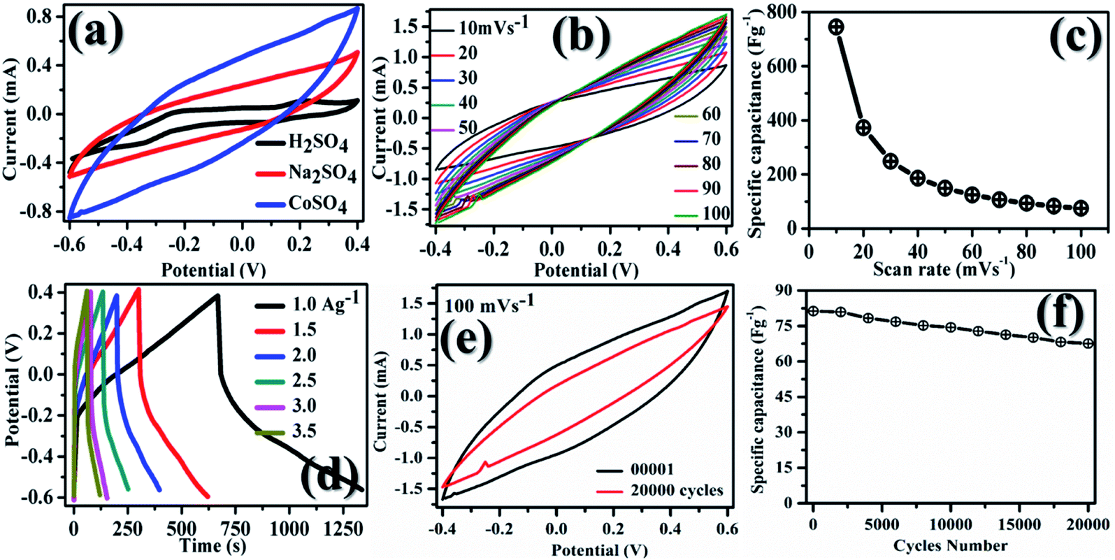 | ||
| Fig. 5 CV measurements on GMH-composite for (a) different aqueous electrolytes (scan rate: 10 mV s−1) with superior performance in CoSO4, (b) variable scan rates between 10 and 100 mV s−1, (c) change in Csp (specific capacitance) with scan rate, (d) stability curves up to 20000 cycles, (e) CV curves recorded after the first and the last cycle, (f) charge–discharge (CD) curves at variable current density (A g−1). Plots (b–f) are CV measurements in CoSO4 electrolyte. | ||
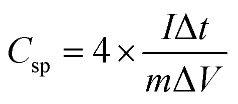
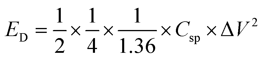
Table 1 shows the specific capacitance, Csp, for the two-electrode technique with the corresponding power, PD, and energy density, ED. The values of Csp for two electrodes are usually lower compared to those of the three-electrode configuration and were calculated using the formulae:
 | (1) |
 | (2) |
 | (3) |
| Current density (A g−1) | 1.0 | 1.5 | 2.0 | 2.5 | 3.0 | 3.5 |
| C sp (F g−1) | 683 | 482 | 401 | 296 | 224 | 214 |
| E D (W h kg−1) | 92.3 | 65.1 | 54.2 | 40.0 | 30.0 | 28.9 |
| P D (W kg−1) | 486 | 729 | 972 | 1213 | 1458 | 1701 |
At lower current density (lower scan rate), both the inner/outer active sites and pores of GMH can be sufficiently accessed by the electrolytic ions, leading to high Csp values. For a high current density or scan rate, only the external surface of the electrode material contributes to the charge/discharge process. It appears that nanosheets significantly shorten the ion diffusion pathways during the CD process and help obtain the high specific capacitance.36Fig. 5(e and f), respectively, show the I–V curves after 1 and 20000 cycles. After 20000 cycles, a slight decrease in the specific capacitance of ∼25% is observed by a reduction in the area under the curve. The good cyclic stability can be attributed to the excellent chemical stability, mechanical strength and flexibility of GMH-composite.43
Table 2 provides a comparison of the performance of other previously reported supercapacitors with the current work. Typically, carbonaceous materials such as graphene, carbon nanotubes, and carbon aerogel have high electrical conductivities and surface areas. Developing TMD hybrids or composite materials with carbon-based materials provides a synergistic effect of the two materials; carbon offers conductive channels and enhanced interfacial contact, while TMDs contribute a short ion diffusion path and successively short electron transport path. GMH-composite shows comparatively good retention stability of 75% up to 20000 cycles.
| Electrode material | Electrolyte | C sp (F g−1) | Cyclic stability | E D (W h kg−1) | P D (kW g−1) | Ref. |
|---|---|---|---|---|---|---|
| MoS2–rGO | 1 M Na2SO4 | 388 @ 1.2 A g−1 | 100% up to 1000 cycles | 44 | ||
| h-BN/rGO | 6 M KOH | 145 @ 6 A g−1 | 89% up to 40000 cycles |
40 | 4200 | 26 |
| Graphene/MnO2 | Ethanol | 315 | 95% up to 5000 cycles | 13 | 110 | 45 |
| Aloe vera-derived carbon | [EMIM][BF4] | 244 | 83% up to 500 cycles | 40 | — | 46 |
| MoS2/rGO | 2 M KOH | 220 @ 1 A g−1 | 91.8% up to 1000 cycles | — | — | 47 |
| Te/rGO | 1 M H2SO4 | 260 F g−1 @ 0.25 A g−1 | ∼80% up to 10000 cycles |
8 | 250 | 48 |
| GMH-composite | CoSO4 | 215 @ 3.5 A g−1 | 75% up to 20000 cycles |
30 | 1700 | Current work |
After cycling, GMH-composite was analysed with XPS, and it was observed that the chemical environment of the heterostructures is the same as that of pristine samples, as shown in Fig. 6.
 | ||
| Fig. 6 Recorded XPS spectra for the GMH heterostructure after 20000 cycles. | ||
It appears that interlayer electrostatic cross-talk plays an important role when one sheds light on the charging–discharging mechanism of this multi-layered blend composed of rGO, MoS2 and h-BN. The inter-layer stacks of MoS2 and h-BN in conjugation with the rGO layers may be mutually acting as spacer molecular layers that prevent restacking. Further, free radical electrons may be responsible for changing the oxidation state of intercalated Mo, B, N and S atoms, which contributes to the additional charge storage capacity of the blend. On the other hand, the intercalated MoS2 provides additional channels for charge transport and increases the overall conductivity of the electrodes.
The re-hybridization of MoS2 may also be possible with h-BN. This may allow the intercalated ions to move swiftly, providing active charging sites. The dominant electrical double layer capacitor (EDLC) behaviour of the composite GMH electrodes is a synergistic effect of the kinetics for non-faradaic proton adsorption at the interface of MoS2/h-BN/rGO. Fig. 7 shows (a) the Nyquist plot and corresponding (b) Bode plot recorded for the GMH blend. Impedance analysis was employed to study the frequency characteristics of the electrode. The EIS was carried out in 2 M CoSO4 solution over the frequency range of 0.01–10000 Hz.
 | ||
| Fig. 7 (a) Nyquist (the arrow shows the inset), (b) Bode and (c) Ragone plots (the dotted circle indicates our results) for the GMH electrode. | ||
The impedance spectrum of GMH in the high frequency region exhibits a semicircle with a low diameter and a straight line in the low frequency region. The intersection of the real axis in the high frequency region represents the solution resistance Rs and the related charge transfer frequency between the electrode material and the electrolyte. The value of Rs was found to be very low (∼5 Ω), indicating the highly conducting nature of the electrode. The low solution resistance suggests that the GMH cell can be assembled in a series for high voltage applications with a minimum loss of energy. Further, the presence of a straight line in the high frequency region shows ideal supercapacitor behaviour. The inset shows that the enlarged plot consists of a broad, curved line instead of a semicircle, which is due to very low faradaic resistance and is indicative of pseudocapacitive behaviour.
In order to understand the frequency-dependent impedance characteristics of the GMH electrode, the logarithm of the absolute impedance |Z| and the phase shift Φ were studied. The almost linear nature is indicative of swift electron exchange at the solution/electrolyte interface. Two phase angles at 30° and 5° were found in the mid and low frequency regions, respectively, showing the pseudocapacitive behaviour of the blend electrode. This may be due to the diffusive characteristic of the electrode electrons.
Ragone plots were used to compare the performance of the current surfaces; they show the relationship between the power density, PD, and the energy density, ED. The calculated power densities are 486, 729, 1213, 1458, and 1701 W kg−1 and the energy densities are 92.3, 65.1, 54.2, 30, 28.9 W h kg−1, respectively, with various current densities @ 1, 1.5, 2, 2.5, 3, and 3.5 A g−1. The values of Cs, PD, and ED are shown in Table 2 and are compared with those of reported forms of carbon. The material shows good performance in aqueous solution, where the pore accessibility limits the energy excitation at higher power. The Ragone plot shows the utility of GMH in the area of battery application. Therefore, the prepared composite material, GMH, is found to be suitable for application as an ideal electrode material for batteries. The parametric values obtained from the fitting are shown in Table 3.
| Parameter | Magnitude with units | Error (%) | Parameter | Magnitude with units | Error (%) |
|---|---|---|---|---|---|
| Z s | 0.30 kΩ | 10.00 | Q S | 0.10 milli stat C | 07.00 |
| Z 1 | 0.50 kΩ | 10.50 | Q S-GMH | 0.32 stat C | 04.50 |
| Z 2 | 1.50 kΩ | 13.00 | Q G | 0.01 stat C | 01.75 |
| Z 3 | 2.50 kΩ | 23.00 | Q eff | 03.18 milli stat C | 16.00 |
| Z 4 | 3.00 kΩ | 06.70 | L 1 | 14.61 mH | 03.82 |
| Z 5 | 3.50 kΩ | 10.00 | L 2 | 28.74 mH | 04.50 |
In the Nyquist study, a semicircle pattern was obtained with a suppressed shape (shown in respective inset) above the real axis. Using the data values of real and imaginary |Z|, a circuit model was simulated and best fitted for discrete components such as impedance (R), inductance (L), and charge accumulated (Q). The simulated circuit was superimposed onto the GMH heterostructure and is schematically shown in Fig. 8. The impedance component, being a complex entity, can be represented in terms of a constant phase element due to the semi-circular pattern obtained in the Nyquist plot.
 | ||
| Fig. 8 Schematic of the GMH-blend electrode in electrolyte superimposed on the simulated equivalent circuit. | ||
From the schematic, one can see that the equivalent circuit is composed of a series of impedances arising because of the GMH interface, its respective surfaces, the capacitive components (neglected during the simulation), the interface with the solution resistance, the mutual inductance arising from highly conducting graphene/MoS2, and the effective charge accumulating at the grain boundaries. Notably, the sequence of the self-assembled heterostructure is immaterial. All this, together with the constant phasor element, leads to the equation:
| Zeff = Z−α × Lβ × Q−1GMH |
The parameters obtained for the discrete components by the circuit simulation are shown in Table 3. One can see that impedance, Z−α, systematically increases from the bulk solution to the self-assembled heterostructure electrodes, including the charge accumulation dynamics, Q−1GMH. Both mutual inductances, Lβ, increased further by a factor of two in the cases of rGO/h-BN and h-BN/MoS2; this indicates strong synergistic effects because of the combination of the two materials, namely MoS2 and h-BN.
Further, electron spin resonance spectroscopy (ESR) revealed the dynamics of radical electrons in a solid system resonating para-magnetically by absorption of microwave energy. The purpose of ESR analysis is to estimate the diffusion dynamics of these radical electrons in the GMH blend vis-a-vis their individual counterparts.
As a first step towards computing the electron transport parameters, the magnitude of the line width determined by the peak to peak distance, ΔHpp, and the shapes of the ESR spectra were investigated. Fig. 9 shows the variation in intensity with applied magnetic field for rGO, MoS2 and GMH-composite at room temperature. The ESR spectrum of h-BN was not obtained. In the cases of rGO and MoS2, the first absorption derivative dY/dH as a function of the applied field shows an unsymmetrical nature, while for GMH-composite, symmetric and homogenous peaks were observed. Further, the principal parameter governing spintronics usability is the spin-lattice relaxation time, Tsl, which characterizes non-thermal spin states around the lattice. From the measured values of ΔHpp and using 1/Tsl = ((28.0 GHz)/T (in K)) × ΔHpp, the Tsl and electron diffusion length, DL, were measured, with the Fermi velocity assumed to be ∼106 m s−1 in all 2D materials.47–50 For MoS2, the DL was estimated to be ∼200 μm, whereas that for rGO is ∼600 μm. The effective DL was found to be ∼1500 μm for GMH-composite. This indicates that on charging, the electron diffusion is quite high for GMH compared with its individual components. This also supports the conductivity measurements.
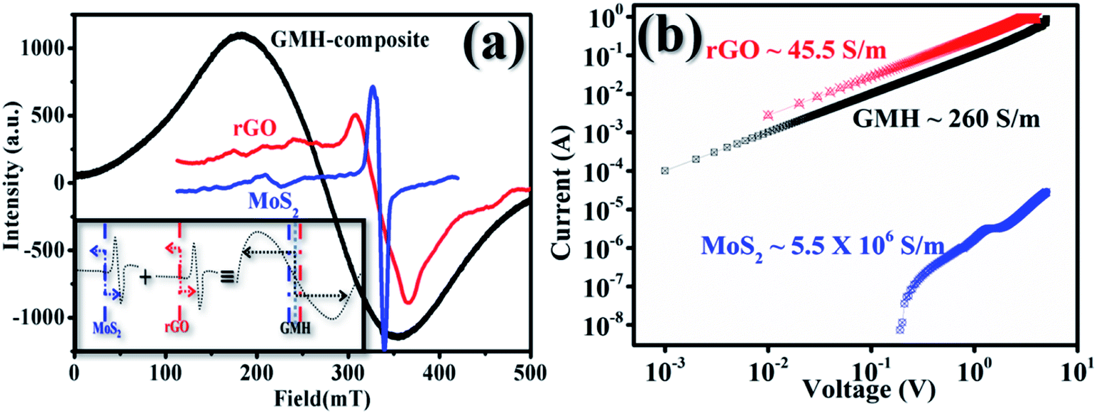 | ||
| Fig. 9 (a) Recorded electron spin resonance profiles for rGO, MoS2, and GMH-composite @ 300 K. The inset shows the scheme of electron diffusion for the individual 2D materials and their composite. The arrows schematically indicate the electron diffusion length, DL, during charging in MOS2, rGO, and GMH-composite, respectively, at 200, 600, and 1500 μm. (b) Recorded I–V profiles for rGO, MoS2, and GMH-composite @ 300 K indicating the specific conductance. In both measurements, profiles for h-BN were not obtained. | ||
Plot (b) shows the IV plots for rGO, MoS2 and GMH using two-probe conductivity measurements at room temperature. In the case of h-BN, no such curve was obtained. The calculated specific conductivity values of prepared pallets of rGO, MoS2 and GMH are 45.5 ± 3.5, 5.5 ± 15 × 106, and 260 ± 30 S m−1 respectively. The specific conductivity of rGO is very high compared to those of GMH and MoS2. The observed decrease is due to the presence of h-BN in the composite. Due to this, the magnitude of Tsl and the implication of DL prove that the composite material is good for energy storage. Therefore, we further prepared a cell with the GMH blend, and its performance was tested.
3.5 GMH cell: performance
GMH-composite was implemented as an active electrode material for a laboratory scale demonstration of blend-cell action. The electrodes were developed as described in ref. 35; Fig. 10(a) shows the corresponding apparatus, starting materials, flat electrodes, etc. The assembly was packed with aluminium foil, as shown in image (b). Prior to charging, the voltage between the two electrodes was measured and was found to be negligibly small (∼0.01 mV). The assembly was connected to croc-clips with conducting wires. The cell was charged for about 1.5 min with a nominal 12.50 V automobile battery. The voltage was instantaneously measured to be ∼12.30 V after charging, as shown in image (c). The voltage decreased gradually with time, indicating recombination of developed charges across the 2D materials. The Helmholtz layer degradation time was found to be very small for such a primitive assembly. The charging measurements were performed repetitively. In one case, we connected the assembly to a commercially available LED equipped with current-carrying wires. The LED was found to be illuminated, as shown in image (c), for a period of approximately 5 min. These results show laboratory scale performance of the fabricated electrode using the GMH molecular blend. No such effect was observed for an rGO specimen prepared and tested in identical fashion.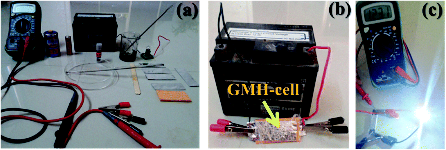 | ||
| Fig. 10 Laboratory scale demonstration of GMH electrode demonstrating LED illumination. (a) Apparatus with the substrate, digital multimeter, 12.4 V commercial automobile battery, active electrode material, carbon powder, PVDF, etc., (b) charging of the blend-cell with a battery, (c) LED illumination after charging, indicating the voltage attained by the fully sealed fabricated blend electrode assembly. | ||
Further ESCA analysis of GMH-composite after 20000 cycles revealed that there was no change in the elemental composition of GMH (ESI Fig. S1†).
4. Conclusions
We have developed a porous self-assembled nano-composite medium of 2D materials comprised of GMH, rGO, MoS2, and h-BN to use as an active material for evaluating supercapacitor performance. The symmetrical EDLC electrodes prepared using the GMH blend showed the highest Csp of ∼683 F g−1 @ 1 A g−1 (current density) with the highest energy density, ED, of ∼90 W h kg−1; meanwhile, the power density, PD, was ∼1700 W kg−1. The ESR studies underline that the diffusion length of the electrons is increased to a large extent, which effectively benefits the migration of electrolytic ions into the multi-layered structures. The presence of a small semicircle in the high frequency region shows favourable solution resistance and an effective charge transfer mechanism between the blend and electrolyte. At high frequency, the electrode shows behaviour of an ideal supercapacitor compounded with marginally low faradaic resistance. The phase angles of 30° and 5° in the mid and low frequency regions, respectively, are indicative of hybrid behaviour as analysed by Bode. The Ragone analysis indicated electrode performance in the battery-like region. The present study suggests that this unique combination of GMH is an ideal material for high performance supercapacitor applications.Conflicts of interest
There is no conflict to declare.References
- K. S. Kumar, N. Choudhary, Y. Jung and J. Thomas, ACS Energy Lett., 2018, 3, 482 CrossRef.
- Z. Yu, L. Tetard, L. Zhai and J. Thomas, Energy Environ. Sci., 2015, 8, 702 RSC.
- N. Choudhary, C. Li, J. Moore, N. Nagaiah, L. Zhai, Y. Jung and J. Thomas, Adv. Mater., 2017, 21, 1605336 CrossRef PubMed.
- M. Chhowalla, Z. Liu and H. Zhang, Chem. Soc. Rev., 2015, 44, 2584 RSC.
- Y. Hou, J. Li, Z. Wen, S. Cui, K. Hippalgaonkar and J. Chen, Nano Energy, 2014, 8, 157 CrossRef.
- Y. Zhang, Y. Zheng, K. Rui, H. Hng, K. Hippalgaonkar, J. Xu, W. Sun, J. Zhu, Q. Yan and W. Huang, Small, 2017, 13, 1700661 CrossRef PubMed.
- S. Zhang, F. Yao, L. Yang, F. Zhang and S. Xu, Carbon, 2015, 93, 143 CrossRef.
- A. Lipatov, M. Alhabeb, M. R. Lukatskaya, A. Boson, Y. Gogotsi and A. Sinitskii, Adv. Electron. Mater., 2016, 2, 1600255 CrossRef.
- Y. Wang, Z. Shi, Y. Huang, Y. Ma, C. Wang, M. Chen and Y. Chen, J. Phys. Chem. C, 2009, 113, 13103 CrossRef.
- V. L. Pushparaj, M. M. Shaijumon, A. Kumar, S. Murugesan, L. Ci, R. Vajtai, R. J. Linhardt, O. Nalamasu and P. M. Ajayan, Proc. Natl. Acad. Sci. U. S. A., 2007, 104, 13574–13577 CrossRef.
- C. Meng, C. Liu, L. Chen, C. Hu and S. Fan, Nano Lett., 2010, 10, 4025 CrossRef.
- Z. S. Wu, D. W. Wang, W. Ren, J. Zhao, G. Zhou, F. Li and H. M. Cheng, Adv. Funct. Mater., 2010, 20, 3595 CrossRef.
- F. Zhang, Y. Tang, H. Liu, H. Ji, J. Jiang, X. Zhang and C. S. Lee, ACS Appl. Mater. Interfaces, 2016, 8, 4691 CrossRef.
- Y. Ge, R. Jalili, C. Wang, T. Zheng, Y. Chao and G. G. Wallace, Electrochim. Acta, 2017, 235, 348 CrossRef.
- J. M. Soon and K. P. Loh, Electrochem. Solid-State Lett., 2007, 10, A250 CrossRef.
- M. Yang, J. M. Jeong, Y. S. Huh and B. G. Choi, Compos. Sci. Technol., 2015, 121, 123 CrossRef.
- C. Yang, Z. Chen, I. Shakir, Y. Xu and H. Lu, Nano Res., 2016, 9, 951 CrossRef.
- M. A. Bissett, I. A. Kinloch and R. A. Dryfe, ACS Appl. Mater. Interfaces, 2015, 7, 17388 CrossRef.
- S. Patil, A. Harle, S. Sathaye and K. Patil, CrystEngComm, 2014, 6, 10845 RSC.
- K. J. Huang, L. Wang, Y. J. Liu, Y. M. Liu, H. B. Wang, T. Gan and L. L. Wang, Int. J. Hydrogen Energy, 2013, 38, 14027 CrossRef.
- J. Wang, Z. Wu, K. Hu, X. Chen and H. Yin, J. Alloys Compd., 2015, 619, 38 CrossRef.
- G. Ma, H. Peng, J. Mu, H. Huang, X. Zhou and Z. Lei, J. Power Sources, 2013, 229, 72–78 CrossRef.
- J. Wang, Z. Wu, H. Yin, W. Li and Y. Jiang, RSC Adv., 2014, 4, 56926 RSC.
- T. W. Lin, T. Sadhasivam, A. Y. Wang, T. Y. Chen, J. Y. Lin and L. D. Shao, ChemElectroChem, 2018, 5, 1024 CrossRef.
- T. W. Lin, M. C. Hsiao, A. Y. Wang and J. Y. Lin, ChemElectroChem, 2017, 4, 620 CrossRef.
- S. Saha, M. Jana, P. Khanra, P. Samanta, H. Koo, N. C. Murmu and T. Kuila, ACS Appl. Mater. Interfaces, 2015, 7, 14211 CrossRef PubMed.
- N. Tronganh, Y. Yang, F. Chen, M. Lu, Y. Jiang, Y. Gao, L. Cheng and Z. Ziao, RSC Adv., 2016, 6, 74436 RSC.
- L. Chen, Y. Yang, Y. Gao, N. Tronganh, F. Chen, M. Lu, Y. Jiang, Z. Jiao and B. Zhao, RSC Adv., 2016, 6, 99833 RSC.
- B. Zhao, Z. Wang, Y. Gao, L. Chen, M. Lu, Z. Jiao, Y. Jiang, Y. Ding and L. Cheng, Appl. Surf. Sci., 2016, 390, 209–215 CrossRef CAS.
- W. S. Hummers and R. E. Offeman, J. Am. Chem. Soc., 1958, 80, 1339 CrossRef CAS.
- L. M. Ansaloni and E. M. de Sousa, Mater. Sci. Appl., 2013, 4, 22 Search PubMed.
- P. K. Panigrahi and A. Pathak, J. Nanopart., 2013, 2013, 671214 Search PubMed.
- S. A. Haladkar, M. A. Desai, S. D. Sartale and P. S. Alegaonkar, J. Mater. Chem. A, 2018, 6, 7246 RSC.
- E. M. E. Mora, New Icosahedral Boron Carbide Semiconductors, Doctoral dissertation, The University of Nebraska-Lincoln, 2017.
- Y. Kang, Z. Chu, D. Zhang, G. Li, Z. Jiang, H. Cheng and X. Li, Carbon, 2013, 61, 200 CrossRef CAS.
- Z. L. Wang, D. Xu, Y. Huang, Z. Wu, L. M. Wang and X. B. Zhang, Chem. Commun., 2012, 48, 976 RSC.
- M. P. Bichat, E. Raymundo-Piñero and F. Béguin, Carbon, 2010, 48, 4351 CrossRef CAS.
- Y. Yao, K. Ao, P. Lv and Q. Wei, Nanomaterials, 2019, 9, 844 CrossRef.
- G. Eda, H. Yamaguchi, D. Voiry, T. Fujita, M. Chen and M. Chhowalla, Nano Lett., 2011, 11, 5111 CrossRef CAS.
- Y. M. Cai, Z. Y. Qin and C. Long, Prog. Nat. Sci.: Mater. Int., 2011, 21, 460–466 CrossRef.
- V. H. Pham, K. H. Kim, D. W. Jung, K. Singh, E. S. Oh and J. S. Chung, J. Power Sources, 2013, 244, 280 CrossRef CAS.
- M. C. Hsiao, C. Y. Chang, L. J. Niu, F. Bai, L. J. Li, H. H. Shen, J. Y. Lin and T. W. Lin, J. Power Sources, 2017, 345, 156 CrossRef CAS.
- H. Li, R. Y. Tay, S. H. Tsang, W. Liu and E. H. T. Teo, Electrochim. Acta, 2015, 166, 197–205 CrossRef CAS.
- M. Saraf, K. Natarajan and S. M. Mobin, ACS Appl. Mater. Interfaces, 2018, 10, 16588 CrossRef CAS.
- G. Yu, L. Hu, M. Vosgueritchian, H. Wang, X. Xie, J. R. McDonough, X. Cui, Y. Cui and Z. Bao, Nano Lett., 2011, 11, 2905 CrossRef CAS.
- M. Karnan, K. Subramani, N. Sudhan, N. Ilayaraja and M. Sathish, ACS Appl. Mater. Interfaces, 2016, 8, 35191 CrossRef CAS PubMed.
- W. Xiao, W. Zhou, T. Feng, Y. Zhang, H. Liu and L. Tian, Materials, 2016, 9, 783 CrossRef PubMed.
- A. P. Alegaonkar, A. Kumar, S. H. Patil, K. R. Patil, S. K. Pardeshi and P. S. Alegaonkar, J. Phys. Chem. C, 2013, 117, 27105 CrossRef CAS.
- A. P. Alegaonkar, M. A. Mahadadalkar, P. S. Alegaonkar, B. B. Kale and S. K. Pardeshi, Electrochim. Acta, 2018, 291, 225 CrossRef CAS.
- S. Saha, M. Jana, P. Khanra, P. Samanta, H. Koo, N. C. Murmu and T. Kuila, ACS Appl. Mater. Interfaces, 2015, 7, 4211 Search PubMed.
Footnote |
| † Electronic supplementary information (ESI) available. See DOI: 10.1039/d0na00021c |
| This journal is © The Royal Society of Chemistry 2020 |