
 Open Access Article
 This Open Access Article is licensed under a Creative Commons Attribution-Non Commercial 3.0 Unported Licence
In situ carbon-supported titanium dioxide (ICS-TiO2) as an electrode material for high performance supercapacitors
Rahul
Kumar
 *ab,
Balwant Kumar
Singh
a,
Ankur
Soam
c,
Smrutiranjan
Parida
a,
Veena
Sahajwalla
b and
Parag
Bhargava
a
*ab,
Balwant Kumar
Singh
a,
Ankur
Soam
c,
Smrutiranjan
Parida
a,
Veena
Sahajwalla
b and
Parag
Bhargava
a
aDepartment of Metallurgical Engineering and Materials Science, Indian Institute of Technology Bombay, Mumbai, 400076, India. E-mail: kumarrahul003@gmail.com
bCentre for Sustainable Materials Research and Technology (SMaRT), School of Materials Science and Engineering, University of New South Wales, NSW 2052, Australia
cDepartment of Mechanical Engineering, Siksha ‘O’ Anusandhan University, Khandagiri Square, Bhubaneswar-751030, Odisha, India
First published on 21st April 2020
Abstract
Supercapacitors have attracted significant attention in the last few years as they have the capability to fulfill the demand for both power and energy density in many energy storage applications. In this study, an in situ carbon-supported titanium oxide (ICS-TiO2) electrode has been prepared using sucrose and TiO2 powder. The ICS-TiO2 powder was prepared by slipcasting, followed by the annealing of the TiO2 slurry. Sucrose was added to the TiO2 slurry as a soluble carbon source, and was converted into carbon at 600 °C then coated on the TiO2 particles. The morphological and structural evolution of the electrode was investigated by FEG-SEM, FEG-TEM, XRD, BET, FTIR, XPS and Raman spectroscopy. The electrochemical characterization of ICS-TiO2 demonstrated that this material exhibits an efficient value of specific capacitance (277.72 F g−1 at 25 mV s−1) for charge storage. ISC-TiO2 also exhibits a specific capacitance of 180 F g−1 at 2 A g−1 in a 1 M Na2SO4 aqueous electrolyte. The results suggest that ICS-TiO2 can be utilized as a high-performance electrode material for supercapacitors with desirable electrochemical properties.
1. Introduction
Electrical energy storage devices are essential in our daily life due to their increasingly vital role.1,2 The current advancement of flexible, wearable and portable electronic devices has been inspired by fast development due to the many advantages such as being thin, light-weight and flexible. These energy storage systems are providing efficient energy management. In particular, flexible energy storage devices have been attracting much attention because of their potential applications in several electronic systems.3–7 Supercapacitors (SCs) are considered one of the most promising power sources for portable systems and various automotive applications because of their high power density, long life cycle fast charge–discharge rates and simple mechanism.8–10 Flexible supercapacitors are easy to fabricate and they have high capacity, long cycle life, low cost of fabrication.11 Moreover, they have a relatively low energy density.12Carbon materials are a good choice for supercapacitors because they possess high electronic conductivity, high specific surface area and excellent stability, and include activated carbon, carbon nanotubes (CNTs), and graphene. Carbon-based supercapacitor electrodes exhibit high power density and are used in flexible electronics because of their high stiffness.13–15 Carbon materials possess low energy density and confined ionic reachability, which is a problem in their consideration as electrode materials.16,17
In contrast, supercapacitors fabricated by transition metal oxide (RuO2, MnO2, NiO, TiO2 and Fe2O3, etc.) have high energy densities and specific capacitance. Among these transition metal oxides for supercapacitors, RuO2 and RuOxHy have exhibited the highest specific capacitance; however, the cost of ruthenium oxide-based materials is very high.18,19 To increase the energy density and specific capacitance of supercapacitors, metal oxides (MnO2, NiO, TiO2 and Fe2O3etc.) in different forms have also been used as efficient materials for supercapacitors.20–28 They are used in supercapacitor electrodes but they have some limitations such as their very low conductivity, and the charge transfer resistance and sheet resistance of the electrode increases due to this. It has been observed that poor flexibility and low power density have been obtained in supercapacitors made by metal oxides due to their intrinsic rigidity.29–31 However, the capacitance of carbon-based supercapacitors could be improved by metal oxides, as they can provide pseudocapacitance despite the double-layer capacitance of carbon materials. The energy storage mechanism in supercapacitors is because of the pseudocapacitance increasing from charge transfer between the electrolyte and electrode via a fast-faradaic redox reaction.32
Titanium dioxide (TiO2) has been considered as a potential candidate for supercapacitor applications due to its natural abundance, low cost, and environmental friendliness.33–35 Nanostructured TiO2 is also an excellent choice as the electrode material for supercapacitor application. The nanostructured material provides enhanced surface area for the adsorption of ions on the electrode. Wang et al. have studied nanocrystalline TiO2 (anatase) for both capacitive and lithium intercalation processes. The non-faradaic storage behaviour of TiO2 has been observed in the aqueous electrolytes. This could be due to the negligible contribution of Ti4+ to Ti3+ redox reactions.36
Kim et al. obtained an areal capacitance of 2.4 mF cm−2 (at 50 mV s−1) and a specific capacitance of 200 F g−1 (at 0.5 mA cm−2).37 It was observed that the charge storage was mainly dependent on the crystallinity, length of the tubes and electrolyte pH value, and the specific capacitance increased on increasing the aspect ratio of the TiO2 nanotubes. A specific capacitance of 1.77 mF cm−2 was obtained with nanotube length 4.95 μm and diameter of 110 nm. The capacitance was enhanced because of the increase in the surface area of the ions.38 A flexible electrode of TiO2 nanowire with reduced graphene oxide was also developed for solid-state supercapacitors. The rGO increases the electrical conductivity of the electrode and the effective surface area to the electrolyte to improve the supercapacitor performance.39 Wang et al. synthesized TiO2–C@polyaniline (PANI) for flexible supercapacitor application. The TiO2–C nanowire arrays enhance the mechanical stability of composites and PANI coated on TiO2–C provides a continuous conductive 3D network.40
TiO2 has had less consideration as a potential electrode material for supercapacitor applications among the various pseudocapacitive materials because of its poor electrochemical activity and low electrical conductivity, due to its wide bandgap semiconductor characteristics.41 TiO2 is generally used in addition to reduced graphene oxide (RGO) as a spacer to inhibit the restacking of RGO sheets.42–44 In 2011, Chen et al. observed that the hydrogenation of TiO2 nanocrystals induced disorder in the surface layer of TiO2 nanocrystals with simultaneous dopant incorporation; this is as a result of the significant decrement in the band gap, which enhances the electrical conductivity of TiO2. The hydroxyl groups formed on the TiO2 surface during hydrogenation could change the electrochemical activity of TiO2 and hence enhance its pseudocapacitance.45 Lu et al. first introduced hydrogenated TiO2 nanotube arrays as electrode materials for supercapacitors.46,47
Unfortunately, it was observed in previous studies that the specific capacitance of metal oxide-based supercapacitors falls considerably with an enhancement in the scan rate due to their poor electronic conductivity. So, it is worth adding metal oxides to carbon materials to fabricate the composites, which can add the merits of both components and reduce the shortcomings of each component.48–54
In the present work, in situ carbon-coated titanium dioxide (ICS-TiO2) has been investigated as an electrode material for supercapacitor application. ICS-TiO2 was prepared by using titanium dioxide slurry and sucrose as a soluble source of carbon. In particular, TiO2 nanoparticles (NPs) were utilized to make the TiO2 slurry. Sucrose was converted into carbon and coated on the TiO2 particles with heat treatment at a moderate temperature (600 °C). The supercapacitor performance of ICS-TiO2 was evaluated using cyclic voltammetry and a charging/discharging process at constant current.
2. Experimental
2.1. Fabrication of ICS-TiO2
The titania slurry was made by using TiO2 nanopowder, (P25, Degussa), polyethylene glycol (Mw = 600) PEG-600 (Thomas Baker) and distilled water. Sucrose (GR-Merck) was added to a solution containing 10 volume % ceramic (TiO2) and upon decomposition at 600 °C, would produce carbon to the extent of 8 wt% with respect to the ceramic. Grinding media (zirconia, 2–3 mm diameter) was added to the slurry and the ratio of the grinding media and titania powder was 1![[thin space (1/6-em)]](https://www.rsc.org/images/entities/char_2009.gif) :1. A polypropylene bottle that had been kept on a pot mill for about 24 h was used to make the slurry.55–57
:1. A polypropylene bottle that had been kept on a pot mill for about 24 h was used to make the slurry.55–57
After preparation of the slurry, ring-shaped plastic molds were used to cast the slurry and these molds were kept on a gypsum base plate and the slurry was cast in the molds. The inner surface of the plastic molds was coated with WD40 (WD Company) to decrease the adhesion between the cast body and the molds. Green body cast samples were disassembled from the plastic molds after drying in ambient conditions for 36 hours. The samples were further dried in an oven at 50 °C for 24 h. The dried samples were disintegrated with a motorized pestle to make a fine powder.50 The annealing of the powder was carried out in flowing argon gas at 600 °C, with heating at 2 °C min−1 up to 600 °C, followed by a dwell time of 2 h at 600 °C to carbonize the sucrose. After the annealing of the powder, we obtained the ICS-TiO2 black powder, which was utilized to prepare the electrodes for the supercapacitor.
2.2. Fabrication of free-standing, flexible, binder-free electrodes
Sonication and drying methods were used to fabricate the free-standing, flexible and binder-free electrodes. In this method, cotton wipes were used to support the active material. Here, 20 mg of ICS-TiO2 black powder was added to 10 mL of ethanol to maintain a concentration of 2 mg mL−1 to make a dispersion of active material. The dispersion was kept in a bath sonicator for about 30 minutes to minimize the agglomerations and to form binder-free black titania ink. A 2 × 2 cm2 cotton wipe was kept in the binder-free black ink prepared by ICS-TiO2 and soaked for a few minutes to fabricate the electrodes. The wipe soaked in ink was then sonicated for a limited time. The active material was homogeneously coated on the fabric of the wipe during this process. The required mass of the active material on the wipe depends on the sonication time, which was optimized for the mass loading of ICS-TiO2. The electrode was dried at 70 °C in an oven after the loading process.58 The mass of ICS-TiO2 black powder was obtained by calculating the difference in weight before and after loading. The active mass of the material was 1.5 mg. ICS-TiO2 (active material) loaded on the cotton-wipe electrodes showed excellent adhesive and mechanical properties; the wipes could be folded and stretched without the detachment of the ICS-TiO2 particles. The schematic of the supercapacitor is shown in Fig. 1.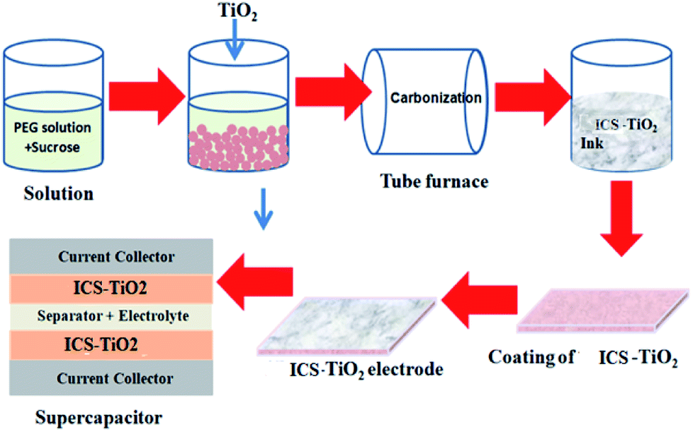 | ||
| Fig. 1 Schematic of ICS-TiO2-based supercapacitors. | ||
2.3. Characterization
The properties of ICS-TiO2 were confirmed by the BET method, field emission gun electron transmission microscopy (FEG-TEM) (JEOL, JEM-2100F), field emission gun electron scanning microscopy (FEG-SEM) (JEOL, JSM-7600F), X-ray powder diffraction (XRD) (Expert Pro, 40 kV, 30 mA, Panalytical), Raman spectroscopy (Jobin-Yvon, France Ramnor HG-2S Spectrometer), Fourier-transform infra-red spectroscopy (FTIR) (Nicolet 5700 spectrometer), thermogravimetric analysis (TGA) (SDTA 851 Mettler-Toledo system), and X-ray photoelectron spectroscopy (XPS) (Kratos Analytical, UK, model-AXIS Supra), independently.2.4. Electrochemical measurements
The cyclic voltammetry (CV) and galvanostatic charge–discharge (GCD) measurements of ICS-TiO2 were performed in a two-electrode symmetric cell configuration compiled into a Swagelok cell. A tea-bag cloth was used as a separator, which was soaked in 1 M Na2SO4 and kept between two active electrodes to separate them. The electrochemical characterization of the device was carried out by CV and GCD measurements using a Biologic Potentiostat SP-300 instrument. The CV measurements were carried out at different scan rates of 10–200 mV s−1 in the potential range of −0.5 to +0.5 V. Galvanostatic charge/discharge curves were obtained at different current densities of 2–5 A g−1 in the potential range of −0.5 to +0.5 V.3. Results and discussion
The morphological properties and the distribution of the particles in ICS-TiO2 were measured using FEG-SEM as demonstrated in Fig. 2(a and b) at two different magnifications. The particles showed some agglomeration. The high magnification SEM image displayed in Fig. 2(b) shows the particle size of ICS-TiO2 in the range of 10–20 nm. The uniform dispersion of carbon particles in the electrodes enhanced the porosity (voids) and the carbon particles and TiO2 particles formed a conducting network for charge transfer. This porous structure could provide more inner surface to the electrolyte ions with enhanced specific capacitance value. For further study, FEG-TEM was performed to determine the morphological and structural features of the as-synthesised ICS-TiO2 sample. The FEG-TEM images of the ICS-TiO2 sample are shown in Fig. 2(c–e). The average particle size was measured using FEG-TEM to be in the range of 8–20 nm, which is almost similar to that calculated from the SEM image. The diffraction pattern of the ICS-TiO2 shows the multi-crystalline nature of the prepared ICS-TiO2 as shown in Fig. 2(f).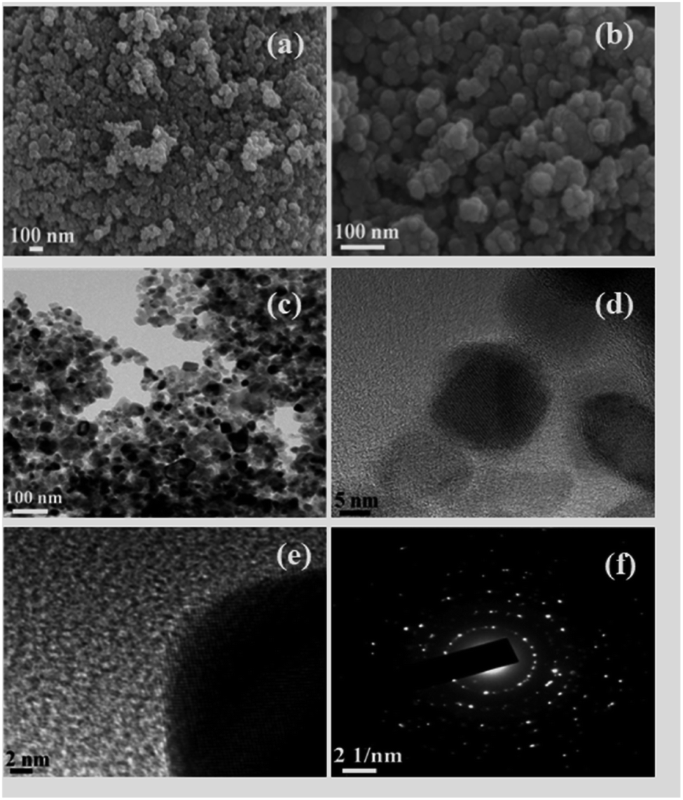 | ||
| Fig. 2 FEG-SEM micrographs of ICS-TiO2 (a) at low magnification and (b) at high magnification; FEG-TEM micrographs (c) at low magnification, and (d) & (e) at high magnification; (f) diffraction pattern of ICS-TiO2. | ||
The surface area of the TiO2 and ICS-TiO2 was measured by the BET method. The Barrett–Joyner–Halenda (BJH) method was used to determine the mesopore surface area, pore volume, and pore diameter of the TiO2 and ICS-TiO2. Nitrogen adsorption/desorption experiments were carried out on the TiO2 and ISC-TiO2. The corresponding isotherms and pore size distributions are shown in Fig. 3(a and b). All the nitrogen adsorption/desorption isotherms are ‘type I’ isotherms as exhibited by the steep rise in the adsorbed volume of N2, indicating the low level of microporosity in TiO2.59
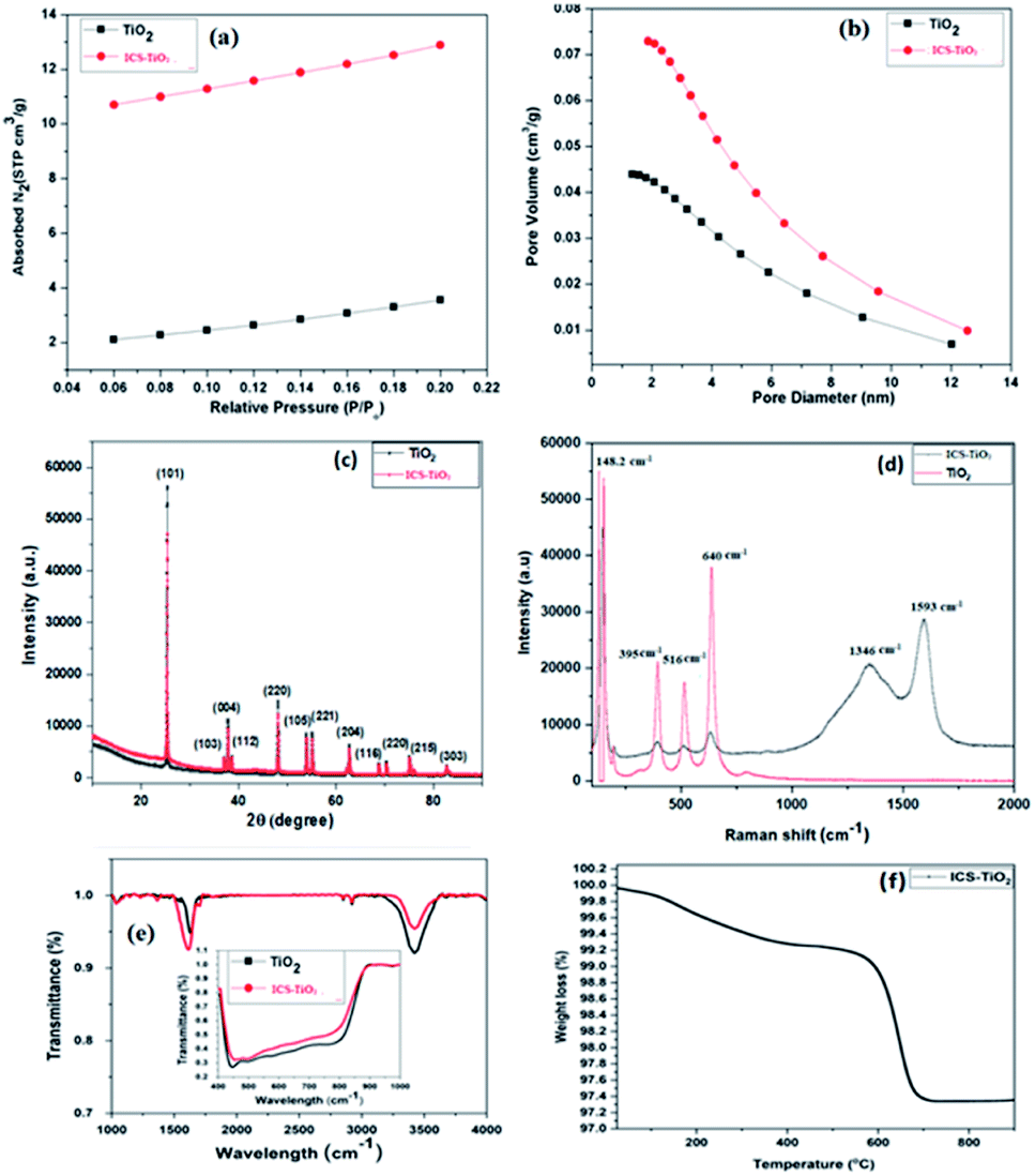 | ||
| Fig. 3 (a) Nitrogen adsorption/desorption isotherms; (b) nitrogen desorption/desorption pore size distribution; (c) XRD pattern, (d) Raman spectra; (e) FTIR spectra of TiO2 and ICS-TiO2; (f) TGA of ICS-TiO2. | ||
TiO2 and ICS-TiO2 exhibited different nitrogen adsorption/desorption isotherms and pore size distributions as shown in Fig. 3(a and b), which is also evident from the obtained SBET (SBET–TiO2 = 14.52 m2 g−1 and SBET–ISC-TiO2 = 45.21 m2 g−1), pore volume (PV–TiO2 = 0.043 cm3 g−1 and PV–ISC-TiO2 = 0.082 cm3 g−1) and average pore size values (PS–TiO2 = 5.09 nm and PS–ISC-TiO2 = 4.61 nm), respectively. The SBET value and pore volume of the ICS-TiO2 sample (SBET = 45.21 m2 g−1, PV–ISC-TiO2 = 0.082 cm3 g−1) are greater than those of TiO2, while the average pore size volume is smaller as compared to TiO2. These changes in the values (surface area, pore volume, and average pore size) of ICS-TiO2 may be due to the coating of carbon derived from sucrose on the TiO2 surface during annealing; the carbon coating enhances the surface area and pore volume of TiO2.
The XRD patterns of TiO2 and ICS-TiO2 (Fig. 3(c)) showed twelve peaks commensurate with the crystalline reflections from the (101), (103), (004), (112), (200), (105), (211), (204), (116), (220), (215) and (303) planes, respectively. The maximum intensity observed for planes for the 2θ values were 25.63, 36.90, 38.05, 38.60, 48.45, 53.88, 54.45, 63.15, 69.25, 70.60, 75.35 and 83.26, respectively. The pattern is an index to anatase TiO2. It can be seen from the XRD data that all the peaks are sharp, indicating crystallites of TiO2. The peak intensities for the planes for the ICS-TiO2 sample were slightly lower as compared to the TiO2 sample. This is may be due to the coating of carbon on the TiO2 surface. The presence of carbon was also confirmed by Raman spectroscopy.
Further structural analysis of TiO2 and ICS-TiO2 was carried out via Raman spectroscopy and the results are demonstrated in Fig. 3(d). Four prominent peaks were observed in the Raman spectrum of TiO2. Three peaks were observed at 395, 516, and 640 cm−1, corresponding to the B1g, A1g and Eg modes of anatase TiO2, respectively. The peak at 395 corresponds to the B1g mode, while the peak at 640 cm−1 mainly originated from the symmetric stretching vibration of O–Ti–O in TiO2. Another peak was observed at 516 cm−1, known as the A1g + B1g peak, due to the antisymmetric bending vibration of O–Ti–O.60 Another major sharp band was observed at 148.2 cm−1, which also corresponds to the Eg mode of anatase TiO2.61 We observed two additional prominent peaks in the Raman spectrum of ICS-TiO2 as shown in Fig. 3(d), which are due to carbon produced by the carbonization of sucrose. For carbon, one peak was seen at 1346 cm−1, corresponding to the D band, which is a characteristic of the disorders (like defects, bond disruption and vacancies, etc.) made in the carbon lattice. The second peak was seen at 1593 cm−1, which is known as the G band, and it is a common indicator of the graphitic structures. This band is generated from the vibrational modes of the sp2-bonded carbon atoms. The intensity ratio of the D and G peaks (ID/IG) represents the degree of disorder in the carbonaceous materials.62–71 The ID/IG ratio for the as-prepared ICS-TiO2 material is 0.85, which indicates a moderate degree of graphitization and long-range ordering of graphitic layers. Raman spectra demonstrated the presence of the anatase phase of TiO2 in the ICS-TiO2. The obtained values of the Raman spectra are in good agreement with the values for anatase, as well as nonstoichiometric titanium oxide containing Ti3+. The Ti3+ ions and oxygen vacancies are common defects that are observed in the surface of ICS-TiO2. This type of defect structure forms Ti3+/oxygen vacancies in black TiO2, which can be uniquely detected by Raman spectroscopy.72
The FTIR spectra of TiO2 and ICS-TiO2 are shown in Fig. 3(e). A peak was observed at 1367 cm−1 in ICS-TiO2, which could be attributed to the C–C stretching in ICS-TiO2 due to the coating of carbon on the TiO2 surface. One peak was seen at 1697 cm−1, indicating the formation of Ti–O–C bonds in ICS-TiO2.73 One band was observed at around 1625 cm−1 in both samples, corresponding to the bending modes of water Ti–OH. The second band was the broadest and was observed at 3425 cm−1 in both samples, corresponding to the stretching vibration of the hydroxyl O–H group of the TiO2. The oxygen functional groups were observed in TiO2 and ICS-TiO2 as confirmed by the intensities of the bands.74 Two peaks were also found between 2850–2950 cm−1 in both samples, arising from hydrogen bonding and due to the OH-containing groups present in both samples.75,76 The presence of the carbon retained in the annealed ICS-TiO2 was measured by TGA as demonstrated in Fig. 3(f) in the temperature range from room temperature (25 °C to 900 °C). The weight loss attributable to the loss of carbon by combustion was lower than expected as per the amount of sucrose added. As shown in Fig. 3(f), the actual amount of carbon that must have been incorporated into ICS-TiO2 from the carbonization of sucrose was equivalent to around 35% yield. In ICS-TiO2, around 2.84 wt% carbon was obtained with the sucrose addition of 8 wt% equivalent carbon. The lower weight loss observed in TGA or the lower amount of carbon incorporated in ICS-TiO2 could be due to the loss of some carbon during the annealing step, even though it was carried out in flowing argon.55
The effect of carbon coating on the chemical compositions and chemical bonding of ICS-TiO2 was examined by XPS measurements. Fig. 4(a) shows the XPS survey spectrum of ICS-TiO2. It was expected that C, Ti and O elements would be present. The C 1s spectrum (Fig. 4(b)) shows a broad, asymmetric peak, indicating the coexistence of distinguishable models. The C 1s peak can be divided into four peaks with binding energies at 284.4, 286.3, 288.2 and 290.0 eV, respectively. The main C 1s peak situated at 284.4 eV is attributed to carbon and sp2 carbon from the carbon produced from sucrose. The peak located at 286.3 eV is attributed to defect-containing sp2 carbon. There is a relatively weak peak situated at 288.2 eV, compatible with Ti–O–C bonds. In addition, there is another weak peak observed at 290 eV, commensurate with O–C![[double bond, length as m-dash]](https://www.rsc.org/images/entities/char_e001.gif) O units.77–79 The peaks (Fig. 4(c)) at the binding energies of 459.0 and 464.8 eV can be attributed to Ti 2p3/2 and Ti 2p1/2, respectively. The binding energy values are very close to those reported in the literature, suggesting that the valence state of Ti is +4.80 The O 1s XPS spectrum is shown in Fig. 4(d) and can be divided into three peaks. The peak at 532.2 eV is due to Ti–OH and/or CO and O–CO species, and the peaks at 530.0 eV are commensurate with oxygen anions in the lattice (Ti–O–Ti). The peak at 533.6 eV may be attributed to the carbonyl oxygen of OC–O–Ti bonds or residual –COOH. This is compatible with the result obtained from the C 1s spectrum.81–84
O units.77–79 The peaks (Fig. 4(c)) at the binding energies of 459.0 and 464.8 eV can be attributed to Ti 2p3/2 and Ti 2p1/2, respectively. The binding energy values are very close to those reported in the literature, suggesting that the valence state of Ti is +4.80 The O 1s XPS spectrum is shown in Fig. 4(d) and can be divided into three peaks. The peak at 532.2 eV is due to Ti–OH and/or CO and O–CO species, and the peaks at 530.0 eV are commensurate with oxygen anions in the lattice (Ti–O–Ti). The peak at 533.6 eV may be attributed to the carbonyl oxygen of OC–O–Ti bonds or residual –COOH. This is compatible with the result obtained from the C 1s spectrum.81–84
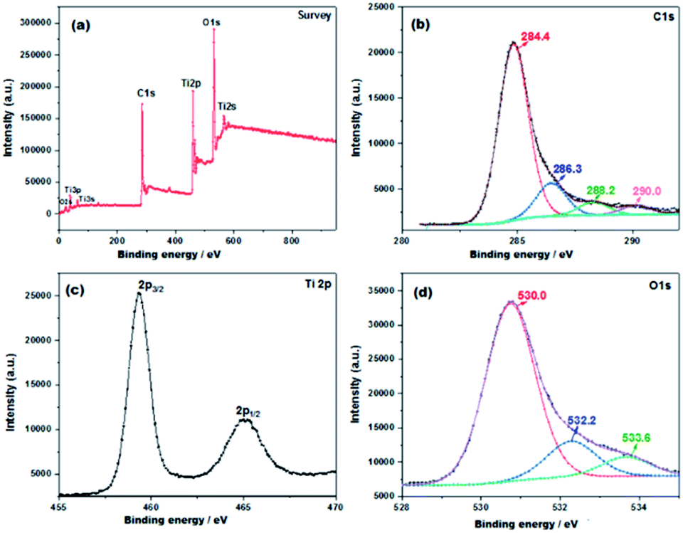 | ||
| Fig. 4 XPS spectra of the ICS-TiO2 (a) XPS survey spectrum; (b) high-resolution C 1s spectrum; (c) high-resolution Ti 2p spectrum; (d) high-resolution O 1s spectrum. | ||
Electrochemical characterization of ICS-TiO2
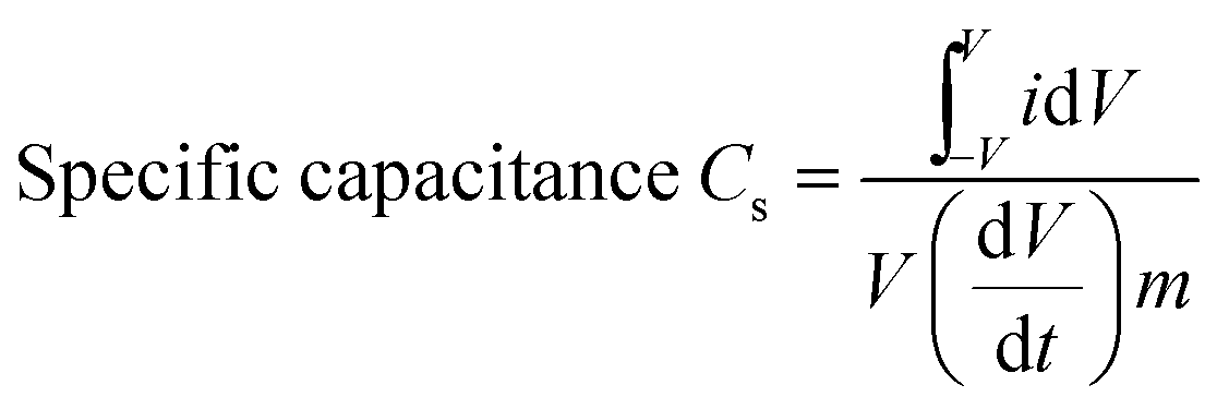
Cyclic voltammetry (CV) measurements were done to determine the capacitive performance of TiO2 and ICS-TiO2 electrodes. CV measurements of TiO2 and ICS-TiO2 were done in 1 M Na2SO4 within the potential window of −0.5 V to +0.5 V as shown in Fig. 5(b). Fig. 5(a) compares the CV curves at the scan rate of 100 mV s−1 of bare TiO2 and the ICS-TiO2-based supercapacitor. It clearly shows that ICS-TiO2 has a larger curve than bare TiO2. ICS-TiO2 has a specific capacitance of 227 F g−1, which is much larger than that of pure TiO2 (53 F g−1). Further, CV curves were recorded for ICS-TiO2 at different scan rates in the range 25–200 mV s−1 as shown in Fig. 5(b). It can be seen from the CV curves of ICS-TiO2 that they have a distorted rectangular shape and consist of redox peaks, which suggest a typical pseudocapacitive nature of the electrodes. The CV curves for the ICS-TiO2 exhibited stable pseudocapacitive properties at different scan rates within the working voltage range of −0.5 to 0.5 V. It can also be seen that anodic peaks shifted negatively and the cathodic peaks shifted positively with the enhancement of the potential sweep rates from 25 to 200 mV s−1. This was due to the variation in the thickness of the diffusion layer on changing the scan rates.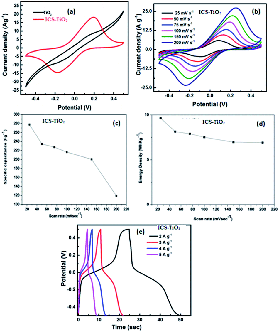 | ||
| Fig. 5 (a) CV curves of TiO2 and ICS-TiO2 recorded at 100 mV s−1. (b) CV curves of ICS-TiO2 recorded at scan rates of 25, 50, 75, 100, 150 and 200 mV s−1. (c) Specific capacitance as a function of scan rate; (d) energy density as a function of the scan rate of ICS-TiO2. (e) Charge and discharge curves of ICS-TiO2 measured at current densities of 2, 3, 4, and 5 A g−1. | ||
The obvious enhancement of current with scan rates indicates a good rate capability for the ICS-TiO2 electrode. The nature of the CV is identical to that reported in an earlier study of TiO2-coated multiwalled carbon nanotubes/graphene/polyaniline nanocomposites.75 The pair of anodic and cathodic peaks within −0.25 V to +0.25 V can be attributed to the faradaic redox reaction of TiO2, similar to previously reported results. In this process, Ti4+ was converted into Ti3+ during charging and the reverse process occurred during discharging, showing the pseudo capacitive behaviour of ICS-TiO2.85 TiO2 is an n-type semiconductor and the surface charge is greater than in the other regions because of the effective contribution of the positively charged depletion region.72
The specific capacitance is directly proportional to the integrated area under the CV curve and it was calculated by using the following eqn (1):86
 | (1) |
 , is the area under the CV curve, V is the potential window (V),
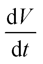 is the scan rate (V s−1) and m is the total mass loading in one electrode.
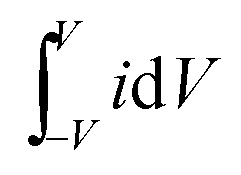
In a symmetrical two-electrode cell configuration, the flexible and binder-free ICS-TiO2 electrode showed the specific capacitances of 277.72, 234.53, 227.49, 216.37, 200.50, and 199.17 F g−1 at scan rates of 25, 50, 75, 100, 150, and 200 mV s−1, respectively. The calculated specific capacitance at different scan rates is plotted in Fig. 5(c). The ICS-TiO2 electrode exhibited a maximum specific capacitance of 277.27 F g−1 at a scan rate of 25 mV s−1 and it decreased on increasing the scan rate. This decrease in the capacitance value with the enhancement in the scan rate is normally due to insufficient time for the ions to penetrate the deep pores. Therefore, at higher scan rates, the ions can participate at the outer surface of the electrode material where the redox reaction takes place. The capacitance is larger at lower scan rates since the ions from the electrolyte could reach into the bulk and access almost all the pores of the electrode material, resulting in the larger value of the capacitance for the same electrode material. The obtained capacitance values are comparable to the reported values for different electrode materials.16,17,85–87 Moreover, the ICS-TiO2 electrode prepared in the present work exhibited specific capacitance values larger than the values recently reported for the TiO2-based electrode. Parastoo Agharezaei et al. fabricated a flexible supercapacitor electrode based on the TiO2/rGO/TiO2 sandwich structure, which showed a capacitance value of 83.7 F g−1 at 5 mV s−1 scan rate.88 The enhanced electrochemical performance may be attributed to two major improvements in the ICS-TiO2 electrode. First, the addition of sucrose enhanced the electrical conductivity of the composite electrode, which improved the charge transport. Second, the surface area of the electrode was enhanced due to the coating of carbon on the TiO2 surface.89,90
The ICS-TiO2 electrode showed the energy densities of 9.64, 8.14, 7.89, 7.51, 6.96, and 6.91 W h kg−1 at scan rates of 25, 50, 75, 100, 150, and 200 mV s−1, respectively, as demonstrated in Fig. 5(d). ICS-TiO2 exhibited the maximum energy density of 9.64 W h kg−1 at a scan rate of 25 mV s−1. ICS-TiO2 also exhibited the power densities of 867.90, 1465.86, 2028.47, 2843.73, 3759.50, and 4979.45 W kg−1 at scan rates of 25, 50, 75, 100, 150, and 200 mV s−1, respectively. ICS-TiO2 showed a higher power density 4979 W kg−1 at a scan rate of 200 mV s−1.
Fig. 5(e) represents the galvanostatic charge/discharge curves of the ICS-TiO2 electrode at different current densities. The curves are not linear, which suggests the charge storage contribution from the pseudocapacitive charge storing mechanism. This is well matched with the results as observed from CV. The charge/discharge duration is reduced with the current densities ranging from 2 to 5 A g−1. There are two clear voltage stages associated with the curves: −0.5 to −0.1 and 0.1 to 0.5 V, respectively. The double layer capacitance is explained by the short charge/discharge duration. The combination of the double-layer capacitance and faradaic capacitance is responsible for the double-layer charging process and the longer charge/discharge duration is because of the faradaic charge-transfer. These results are in accord with the CV tests.91 The specific capacitance of the ICS-TiO2 electrode was calculated according to the following formula:92–94
| Cg = 2A × I/(ΔV)2 × m | (2) |
The power density and energy density are the most vital parameters for any energy storage device. Ragone plots are utilized to explain the energy density of a supercapacitor as a function of the power density. The power density and energy density of ICS-TiO2 electrodes are calculated as per eqn (3) and (4), respectively:92–94
| Power density Pd (W kg−1) = E/Δt | (3) |
 | (4) |
The GCD measurements were recorded over a potential range of −0.5 to +0.5 V with current densities of 2, 3, 4, and 5 A g−1 (Fig. 5(e)). All the GCD curves exhibited symmetrical voltage–time profiles at constant current densities. This is an indicator of high-quality capacitive behaviour with unsurpassed electrochemical reversibility over the entire charge–discharge process. The ICS-TiO2-based supercapacitor device exhibited the specific capacitances of 180, 117, 98, and 83 F g−1 at current densities of 2, 3, 4, and 5 A g−1, respectively. ICS-TiO2 exhibited the maximum specific capacitance of 180 F g−1 at a current density of 2 A g−1, which can be seen from Fig. 6(a). The ICS-TiO2-based supercapacitor device also exhibited the energy densities of 6.25, 4.06, 3.40, and 2.88 W h kg−1 at the current densities of 2, 3, 4, and 5 A g−1, respectively, as shown in Fig. 6(b).
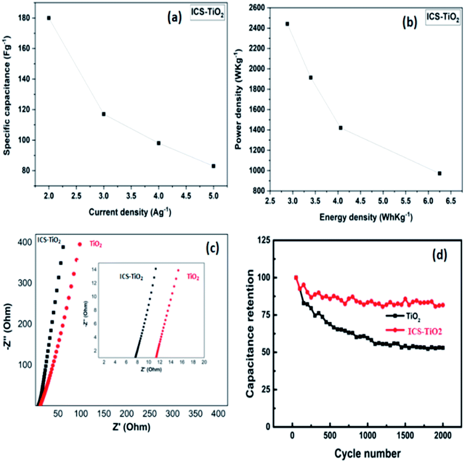 | ||
| Fig. 6 (a) Specific capacitance vs. current density, and (b) power density vs. energy density for ICS-TiO2. (c) EIS spectra of TiO2 and ICS-TiO2; (d) cyclic stability of TiO2 and ICS-TiO2. | ||
The power density and energy density are two important parameters for estimating supercapacitor performance; the Ragone plot of the ICS-TiO2 electrode is shown in Fig. 6(b). The energy density decreases with increasing power density, which may be related to the diffusion limit of ions in the electrolyte and electrodes. The ICS-TiO2 electrode fabricated in the present work showed improved performance in terms of power and energy density as compared to the TiO2 nanofiber-based electrode reported previously.91 The performances of the carbon–TiO2 composites from literature are given in Table 1.88,92,95–98 The improvement in the performance is because of the increased electrical conductivity and surface area of the ISC-TiO2 electrode with the coating of the sucrose-derived carbon.
| Material | C max (F g−1) | Scan rate | Electrolyte | Cell type | Reference |
|---|---|---|---|---|---|
| TiO2/rGO/TiO2 | 83.7 | 5 mV s−1 | 1 M KOH | Two electrodes | 88 |
| rGO–TiO2 nanobelts | 200 | 2 mV s−1 | 1 M Na2SO4 | Two electrodes | 92 |
| rGO/TiO2 nanosheet composite | 305 | 5 mV s−1 | 0.2 M K3[Fe(CN)6] in 1 M Na2SO4 | Two electrodes | 95 |
| C-doped porous TiO2 | 485 | 1 A g−1 | 2 M KOH | Two electrodes | 96 |
| TiO2 commercial | 32 | 10 mV s−1 | 1 M LiPF6 | Two electrodes | 97 |
| TiO2 (synthesized)/rGO | 52 | 10 mV s−1 | 1 M LiPF6 | Two electrodes | 97 |
| rGO–TiO2 composite | 200 | 2 mV s−1 | 1 M Na2SO4 | Two electrodes | 98 |
| ICS-TiO2 | 277.7 | 25 mV s−1 | 1 M Na2SO4 | Two electrodes | Present work |
Electrochemical impedance spectroscopy (EIS) measurements were also conducted in the frequency range from 0.01 to 100 kHz with alternate amplitude voltage of 5 mV (Fig. 6(c)). The series resistance for TiO2 and ICS-TiO2 electrodes were determined to be 7.5 and 11.3 Ω, respectively. The above results clearly indicate the reduction of the series resistance of the ICS-TiO2 electrode as compared with the bare TiO2. Fig. 6(d) shows the capacitance retention of TiO2 and ICS-TiO2 over 2000 cycles. It can be seen that the ICS-TiO2 electrodes exhibited better capacitance retention as compared to TiO2 electrodes while charging/discharging the device many times. These results showed that ICS-TiO2 exhibited better electrochemical stability than TiO2 over prolonged cycles. The above results suggest that the ICS-TiO2 electrode may be used for high-performance supercapacitors.
4. Conclusions
In conclusion, we have synthesized ICS-TiO2 black powder to function as an advanced electrode material for supercapacitors. ICS-TiO2 black powder was obtained after annealing sucrose-coated TiO2 powder in an argon atmosphere at 600 °C. ICS-TiO2-based supercapacitors operated stably in the voltage window of −0.5 V to +0.5 V using 1 M Na2SO4 as an electrolyte. ICS-TiO2 exhibited the specific capacitance of 180 F g−1 at a current density of 2 A g−1. The ICS-TiO2 performance in terms of capacitance, power, and energy density is higher than that reported for the two-electrode cell configuration, which suggests that ICS-TiO2 is a high-performance electrode material for supercapacitors.Conflicts of interest
There are no conflicts to declare.Acknowledgements
This work was supported by IIT Bombay. The authors acknowledge the access to experimental facilities at the Centre for Research in Nanotechnology and Science (CRNTS) and the Metallurgical Engineering and Materials Science (MEMS) Department, IIT Bombay.References
- L. Li, Z. Wu, S. Yuan and X. B. Zhang, Advances and challenges for flexible energy storage and conversion devices and systems, Energy Environ. Sci., 2014, 7, 2101–2122 RSC.
- Y. M. He, W. J. Chen, C. T. Gao, J. Y. Zhou, X. D. Li and E. Q. Xie, An overview of carbon materials for flexible electrochemical capacitors, Nanoscale, 2013, 5, 8799–8820 RSC.
- Y. Z. Zhang, Y. Wang, T. Cheng, W. Y. Lai, H. Pang and W. Huang, Flexible supercapacitors based on paper substrates: a new paradigm for low-cost energy storage, Chem. Soc. Rev., 2015, 44, 5181–5199 RSC.
- T. Cheng, Y. Zhang and W. Y. Lai, Stretchable Thin-Film Electrodes for Flexible Electronics with High Deformability and Stretchability, Adv. Mater., 2015, 27, 3349–3376 CrossRef CAS PubMed.
- R. Kumar, B. Singh, A. Soam, S. Parida and P. Bhargava, In-situ carbon coated manganese oxide nanorods (ISCC-MnO2NRs) as an electrode material for supercapacitors, Diamond Relat. Mater., 2019, 94, 110–117 CrossRef CAS.
- F. Liu, S. Song and D. Xue, Folded Structured Graphene Paper for High Performance Electrode Materials, Adv. Mater., 2012, 24, 1089–1094 CrossRef CAS PubMed.
- H. Gwon, H. S. Kim and K. U. Lee, Flexible energy storage devices based on graphene paper, Energy Environ. Sci., 2011, 4, 1277–1283 RSC.
- P. Simon and Y. Gogotsi, Materials for electrochemical capacitors, Nat. Mater., 2008, 7, 845–854 CrossRef CAS PubMed.
- J. Yan, Q. Wang, T. Wei and Z. Fan, Recent Advances in Design and Fabrication of Electrochemical Supercapacitors with High Energy Densities, Adv. Energy Mater., 2014, 4, 1300816 CrossRef.
- C. Zhong, Y. Deng, W. Hu, J. Qiao, L. Zhang and J. A. Zhang, A review of electrolyte materials and compositions for electrochemical supercapacitors, Chem. Soc. Rev., 2015, 44, 7484–7539 RSC.
- Z. Ling, C. E. Ren, M. Q. Zhao, J. Yang, J. M. Giammarco, J. Qiu, M. W. Barsoum and Y. Gogotsi, Flexible and conductive MXene films and nanocomposites with high capacitance, Proc. Natl. Acad. Sci. U. S. A., 2014, 25, 16676–16681 CrossRef PubMed.
- A. S. Arico, P. Bruce, B. Scrosati, J. M. Tarascon and W. Van Schalkwijk, Nanostructured materials for advanced energy conversion and storage devices, Nat. Mater., 2005, 4, 366–377 CrossRef CAS PubMed.
- Y. Zhai, Y. Dou, D. Zhao, P. F. Fulvio, R. T. Mayes and S. Dai, Carbon Materials for Chemical Capacitive Energy Storage, Adv. Mater., 2011, 23, 4828–4850 CrossRef CAS PubMed.
- F. Zhang, T. Zhang, X. Yang, L. Zhang, K. Leng, Y. Huang and Y. Chen, A high-performance supercapacitor-battery hybrid energy storage device based on graphene-enhanced electrode materials with ultrahigh energy density, Energy Environ. Sci., 2013, 6, 1623–1632 RSC.
- T. Chen and L. Dai, Flexible supercapacitors based on carbon nanomaterials, J. Mater. Chem. A, 2014, 2, 10756–10775 RSC.
- R. Kumar, A. Soam, R. O. Dusane and P. Bhargava, Sucrose derived carbon coated silicon nanowires for supercapacitor application, J. Mater. Sci.: Mater. Electron., 2018, 28, 1947–1954 CrossRef.
- S. Nayak, A. Soam, J. Nanda, C. Mahinder, M. Singh and R. Kumar, Sol–gel synthesized BiFeO3–graphene nanocomposite as efficient electrode for supercapacitor application, J. Mater. Sci.: Mater. Electron., 2018, 29, 9361–9368 CrossRef CAS.
- J. H. Park and O. O. Park, Morphology and electrochemical behaviour of ruthenium oxide thin film deposited on carbon paper, J. Power Sources, 2002, 109, 121–126 CrossRef CAS.
- C. C. Hu, K. H. Chang, M. C. Lin and Y. T. Wu, Design and Tailoring of the Nanotubular Arrayed Architecture of Hydrous RuO2 for Next Generation Supercapacitors, Nano Lett., 2006, 6, 2690–2695 CrossRef CAS PubMed.
- C. D. Lokhande, D. P. Dubal and O. S. Joo, Metal oxide thin film based supercapacitors, Current Applied Physics, 2011, 11, 255–270 CrossRef.
- P. C. Chen, G. Shen, Y. Shi, H. Chen and C. Zhou, Preparation and Characterization of Flexible Asymmetric Supercapacitors Based on Transition-Metal-Oxide Nanowire/Single-Walled Carbon Nanotube Hybrid Thin-Film Electrodes, ACS Nano, 2010, 4, 4403–4411 CrossRef CAS PubMed.
- X. Zhao, C. Johnston and P. S. Grant, A novel hybrid supercapacitor with a carbon nanotube cathode and an iron oxide/carbon nanotube composite anode, J. Mater. Chem., 2009, 19, 8755–8760 RSC.
- D. W. Wang, F. Li and H. M. Cheng, Hierarchical porous nickel oxide and carbon as electrode materials for asymmetric supercapacitor, J. Power Sources, 2008, 185, 1563–1568 CrossRef CAS.
- X. Du, C. Wang, M. Chen, Y. Jiao and J. Wang, Electrochemical Performances of Nanoparticle Fe3O4/Activated Carbon Supercapacitor Using KOH Electrolyte Solution, J. Phys. Chem. C, 2009, 113, 2643–2646 CrossRef CAS.
- H. Jiang, J. Ma and C. Li, Mesoporous Carbon Incorporated Metal Oxide Nanomaterials as Supercapacitor Electrodes, Adv. Mater., 2012, 24, 4197–4202 CrossRef CAS PubMed.
- A. L. M. Reddy and S. Ramaprabhu, Nanocrystalline Metal Oxides Dispersed Multiwalled Carbon Nanotubes as Supercapacitor Electrodes, J. Phys. Chem. C, 2007, 11, 7727–7734 CrossRef.
- R. K. Selvan, I. Perelshtein, N. Perkas and A. Gedanken, Synthesis of Hexagonal-Shaped SnO2 Nanocrystals and SnO2@C Nanocomposites for Electrochemical Redox Supercapacitors, J. Phys. Chem. C, 2008, 112, 1825–1830 CrossRef CAS.
- K. R. Prasad, K. Koga and N. Miura, Electrochemical Deposition of Nanostructured Indium Oxide: High-Performance Electrode Material for Redox Supercapacitors, Chem. Mater., 2004, 16, 1845–1847 CrossRef CAS.
- J. K. Chang and W. T. Tsai, Material Characterization and Electrochemical Performance of Hydrous Manganese Oxide Electrodes for Use in Electrochemical Pseudocapacitors, J. Electrochem. Soc., 2003, 150, A1333–A1338 CrossRef CAS.
- M. Zhi, C. Xiang, J. Li, M. Li and N. Wu, Nanostructured carbon–metal oxide composite electrodes for supercapacitors: a review, Nanoscale, 2013, 5, 72–88 RSC.
- X. Lang, A. Hirata, T. Fujita and M. Chen, Nanoporous metal/oxide hybrid electrodes for electrochemical supercapacitors, Nat. Nanotechnol., 2011, 6, 232–236 CrossRef CAS PubMed.
- G. Arabale, D. Wagh, M. Kulkarni, I. S. Mulla, S. P. Vernekar, K. Vijayamohanan and A. M. Rao, Enhanced supercapacitance of multiwalled carbon nanotubes functionalized with ruthenium oxide, Chem. Phys. Lett., 2003, 376, 207–213 CrossRef CAS.
- M. Salari, S. H. Aboutalebi, K. Konstantinov and H. K. Liu, A highly ordered titania nanotube array as a supercapacitor electrode, Phys. Chem. Chem. Phys., 2011, 13, 5038–5041 RSC.
- A. Elmouwahidi, E. Bailón-García, J. Castelo-Quibén, A. F. Pérez-Cadenas, F. J. Maldonado-Hódar and F. Carrasco-Marín, Carbon–TiO2 composites as high-performance supercapacitor electrodes: synergistic effect between carbon and metal oxide phases, J. Mater. Chem. A, 2018, 6, 633–644 RSC.
- A. Hodaei, A. S. Dezfuli and H. R. Naderi, A high-performance supercapacitor based on N-doped TiO2 nanoparticles, J. Mater. Sci.: Mater. Electron., 2018, 29, 14596–14604 CrossRef CAS.
- A. J. Wang, J. Polleux, J. Lim and B. Dunn, Pseudocapacitive contributions to electrochemical energy storage in TiO2 anatase nanoparticles, J. Phys. Chem. C, 2007, 111, 14925–14931 CrossRef.
- B. M. S. Kim, T. W. Lee and J. H. Park, Controlled TiO2 nanotube array as an active material for high power energy storage devices, J. Electrochem. Soc., 2009, 156, A584 CrossRef.
- C. C. Clement Raj, R. Sundheep and R. Prasanth, Enhancement of electrochemical capacitance by tailoring the geometry of TiO2 nanotube electrodes, Electrochim. Acta, 2015, 176, 1214–1220 CrossRef.
- J. Huo, Y. Xue, C. Cheng and S. Guo, A flexible electrode of TiO2 nanowire arrays modified with graphene for solid-state cable-type supercapacitors, Ionics, 2020, 26, 971–979 CrossRef CAS.
- Q. Wang, J. Wang, H. Wang, J. Zhan, Y. Zhu, Q. Zhang, Q. Shen and H. Yang, TiO2–C nanowire arrays@polyaniline core–shell nanostructures on carbon cloth for high performance supercapacitors, Appl. Surf. Sci., 2019, 493, 1125–1133 CrossRef CAS.
- M. Salari, K. Konstantinov and H. K. Liu, Enhancement of the capacitance in TiO2 nanotubes through controlled introduction of oxygen vacancies, J. Mater. Chem., 2011, 21, 5128–5133 RSC.
- X. Sun, M. Xie, G. Wang, H. Sun, A. S. Cavanagh and J. J. Travis, Atomic Layer Deposition of TiO2 on Graphene for Supercapacitors, J. Electrochem. Soc., 2012, 159, A364–A369 CrossRef CAS.
- A. Ramadoss, G. S. Kim and S. J. Kim, Fabrication of reduced graphene oxide/TiO2 nanorod/reduced graphene oxide hybrid nanostructures as electrode materials for supercapacitor applications, CrystEngComm, 2013, 15, 10222–10229 RSC.
- Z. Zhang, F. Xiao, Y. Guo, S. Wang and Y. Liu, One-Pot Self-Assembled Three-Dimensional TiO2-Graphene Hydrogel with Improved Adsorption Capacities and Photocatalytic and Electrochemical Activities, ACS Appl. Mater. Interfaces, 2013, 5, 2227–2233 CrossRef CAS PubMed.
- X. Chen, L. Liu, P. Y. Yu and S. S. Mao, Increasing Solar Absorption for Photocatalysis with Black Hydrogenated Titanium Dioxide Nanocrystals, Science, 2011, 331, 746–750 CrossRef CAS PubMed.
- X. Lu, G. Wang, T. Zhai, M. Yu, J. Gan and Y. Tong, Hydrogenated TiO2 Nanotube Arrays for Supercapacitors, Nano Lett., 2012, 12, 1690–1696 CrossRef CAS PubMed.
- C. Clement Raj and R. Prasanth, Review—Advent of TiO2 Nanotubes as Supercapacitor Electrode, J. Electrochem. Soc., 2018, 9, E345–E358 Search PubMed.
- S. H. Kim, Y. Kim, J. H. Park and J. M. Ko, Cobalt-Manganese Oxide/Carbon-nanofiber Composite Electrodes for Supercapacitors, Int. J. Electrochem. Sci., 2009, 4, 1489–1496 CAS.
- A. Yuan, X. Wang, Y. Wang and J. Hu, Comparison of nano-MnO2 derived from different manganese sources and influence of active material weight ratio on performance of nano-MnO2/activated carbon supercapacitor, Energy Convers. Manage., 2010, 51, 2588–2594 CrossRef CAS.
- Y. H. Lin, T. Y. Wei, H. C. Chien and S. Y. Lu, Manganese Oxide/Carbon Aerogel Composite: An Outstanding Supercapacitor Electrode Material, Adv. Energy Mater., 2011, 1, 901–907 CrossRef CAS.
- H. Q. Wang, Z. S. Li, Y. G. Huang, Q. Y. Li and X. Y. Wang, A novel hybrid supercapacitor based on spherical activated carbon and spherical MnO2 in a non-aqueous electrolyte, J. Mater. Chem., 2010, 20, 3883–3889 RSC.
- L. Hu, W. Chen, X. Xie, N. Liu, Y. Yang, H. Wu, Y. Yao, M. Pasta, H. N. Alshareef and Y. Cui, Symmetrical MnO2–Carbon Nanotube–Textile Nanostructures for Wearable Pseudocapacitors with High Mass Loading, ACS Nano, 2011, 5, 8904–8913 CrossRef CAS PubMed.
- Q. T. Qu, S. B. Yang and X. L. Feng, 2D Sandwich-like Sheets of Iron Oxide Grown on Graphene as High Energy Anode Material for Supercapacitors, Adv. Mater., 2011, 23, 5574–5580 CrossRef CAS PubMed.
- H. W. Wang, Z. A. Hu, Y. Q. Chang, Y. L. Chen, Z. Y. Zhang, Y. Y. Yang and H. Y. Wu, Preparation of reduced graphene oxide/cobalt oxide composites and their enhanced capacitive behaviors by homogeneous incorporation of reduced graphene oxide sheets in cobalt oxide matrix, Mater. Chem. Phys., 2011, 130, 672–679 CrossRef CAS.
- R. Kumar and P. Bhargava, Synthesis and characterization of low specific resistance alumina-clay–carbon composites by colloidal processing using sucrose as a soluble carbon source for electrical applications, RSC Adv., 2016, 6, 8705–8713 RSC.
- R. Kumar and P. Bhargava, Fabrication of low specific resistance ceramic carbon composites by colloidal processing using glucose as soluble carbon source, Bull. Mater. Sci., 2017, 40, 1197–1202 CrossRef CAS.
- R. Kumar and P. Bhargava, Fabrication of low specific resistance ceramic carbon composites by slip casting, Journal of Asian Ceramic Societies, 2015, 3, 262–265 CrossRef.
- D. Mohapatra, S. Badrayyana and S. Parida, Designing binder-free, flexible electrodes for high-performance supercapacitors based on pristine carbon nano-onions and their composite with CuO nanoparticles, RSC Adv., 2016, 6, 14720–14729 RSC.
- L. Miao, D. Zhu, Y. Zhao, M. Liu, H. Duan, W. Xiong, Q. Zhu, L. Li, Y. Lv and L. Gan, Design of carbon materials with ultramicro, supermicro, and mesopores using solvent- and self-template strategy for supercapacitors, Microporous Mesoporous Mater., 2017, 253, 1–9 CrossRef CAS.
- F. Tian, Y. Zhang, J. Zhang and C. Pan, Raman Spectroscopy: A New Approach to Measure the Percentage of Anatase TiO2 Exposed (001) Facets, J. Phys. Chem. C, 2012, 116, 7515–7519 CrossRef CAS.
- P. Pazhamalai, K. Krishnamoorthy, V. K. Marriappan and S. J. Kim, Blue TiO2 nanosheets as a high-performance electrode material for supercapacitors, J. Colloid Interface Sci., 2019, 536, 62–70 CrossRef CAS PubMed.
- C. T. Hsieh, B. H. Yang and J. Y. Lin, One- and two-dimensional carbon nanomaterials as counter electrodes for dye-sensitized solar cells, Carbon, 2011, 49, 3092–3097 CrossRef CAS.
- R. Kumar, V. More, S. P. Mohanty, S. S. Nemala, S. Mallick and P. Bhargava, A simple route to making counter electrode for dye sensitized solar cells (DSSCs) using sucrose as carbon precursor, J. Colloid Interface Sci., 2015, 459, 146–150 CrossRef CAS PubMed.
- R. Kumar, S. S. Nemala, S. Mallick and P. Bhargava, Synthesis and characterization of carbon based counter electrode for dye sensitized solar cells (DSSCs) using sugar free as a carbon material, Sol. Energy, 2017, 144, 215–220 CrossRef CAS.
- R. Kumar and P. Bhargava, Fabrication of a counter electrode using glucose as carbon material for dye sensitized solar cells, Mater. Sci. Semicond. Process., 2015, 40, 331–336 CrossRef CAS.
- R. Kumar, S. S. Nemala, S. Mallick and P. Bhargava, High efficiency dye sensitized solar cell made by carbon derived from sucrose, Opt. Mater., 2017, 64, 401–405 CrossRef CAS.
- A. Soam, R. Kumar, P. Sahoo, C. Mahender, B. K. Singh, N. Arya, M. Singh, S. Parida and R. O. Dusane, Synthesis of Nickel Ferrite Nanoparticles Supported on Graphene Nanosheets as Composite Electrodes for High Performance Supercapacitor, ChemistrySelect, 2019, 4, 9952–9958 CrossRef CAS.
- R. Kumar and P. Bhargava, Synthesis and characterization of carbon based counter electrode for dye sensitized solar cells (DSSCs) using organic precursor 2-2′ bipyridine (Bpy) as a carbon material, J. Alloys Compd., 2018, 748, 905–910 CrossRef CAS.
- A. Soam, R. Kumar, C. Mahender, M. Singh, D. Thatoi and R. O. Dusane, Development of paper-based flexible supercapacitor: bismuth ferrite/graphene nanocomposite as an active electrode material, J. Alloys Compd., 2019, 813, 152145 CrossRef.
- R. Kumar, V. Sahajwalla and P. Bhargava, Fabrication of a counter electrode for dye-sensitized solar cells (DSSCs) using carbon material produced by organic ligand 2-methyl-8-hydroxyquinolinol (Mq), Nanoscale Adv., 2019, 1, 3292–3299 RSC.
- R. Kumar, A. Raj, S. Mitra and P. Bhargava, Carbon derived from sucrose as anode material for lithium-ion batteries, J. Electron. Mater., 2019, 48, 7389–7395 CrossRef CAS.
- H. Zhang, X. J. Lv, Y. M. Li, Y. Wang and J. H. Li, TiO2–Graphene Nanocomposites for Gas-Phase Photocatalytic Degradation of Volatile Aromatic Pollutant: Is TiO2–Graphene Truly Different from Other TiO2–Carbon Composite Materials, ACS Nano, 2010, 4, 380–386 CrossRef CAS PubMed.
- Y. G. Wang, H. Q. Li and Y. Y. Xia, Ordered Whiskerlike Polyaniline Grown on the Surface of Mesoporous Carbon and Its Electrochemical Capacitance Performance, Adv. Mater., 2006, 18, 2619–2623 CrossRef CAS.
- K. Zhang, K. C. Kemp and V. Chandra, Homogeneous anchoring of TiO2 nanoparticles on graphene sheets for waste water treatment, Mater. Lett., 2012, 81, 127–130 CrossRef CAS.
- H. Abdullah, M. Z. Razali, S. Shaari and M. RaihanTaha, Manipulation of MWCNT Concentration in MWCNT/TiO2 Nanocomposite Thin Films for Dye-Sensitized Solar Cell, Int. J. Photoenergy, 2014, 2014, 673712 CrossRef.
- N. V. Qui, P. Scholz, T. Krech, T. F. Keller, K. Pollok and B. Ondruschka, Multiwalled carbon nanotubes oxidized by UV/H2O2 as catalyst for oxidative dehydrogenation of ethylbenzene, Catal. Commun., 2011, 12, 464–469 CrossRef CAS.
- L. Bin and H. C. Zeng, Three-Dimensional Wormhole and Ordered Mesostructures and Their Applicability as Optically Ion-Sensitive Probe Templates, Chem. Mater., 2008, 20, 2711–2718 CrossRef.
- F. Wang and K. Zhang, Physicochemical and photocatalytic activities of self-assembling TiO2 nanoparticles on nanocarbons surface, Current Applied Physics, 2012, 12, 346–352 CrossRef.
- B. K. Vijayan, N. M. Dimitrijevic, D. F. Shapiro, J. S. Wu and K. A. Gray, Coupling Titania Nanotubes and Carbon Nanotubes To Create Photocatalytic Nanocomposites, ACS Catal., 2012, 2, 223–229 CrossRef CAS.
- G. M. An, W. H. Ma, Z. Y. Sun, Z. M. Liu, B. X. Han, S. D. Miao, Z. J. Miao and K. L. Ding, Preparation of titania/carbon nanotube composites using supercritical ethanol and their photocatalytic activity for phenol degradation under visible light irradiation, Carbon, 2007, 45, 1795–1801 CrossRef CAS.
- J. Zhong, F. Chen and J. L. Zhang, Photocatalytic H2 Evolution on MoS2/CdS Catalysts under Visible Light Irradiation, J. Phys. Chem. C, 2010, 114, 933–939 CrossRef CAS.
- L. J. Chen, F. Chen, Y. F. Shi and J. L. Zhang, Preparation and Visible Light Photocatalytic Activity of a Graphite-Like Carbonaceous Surface Modified TiO2 Photocatalyst, J. Phys. Chem. C, 2012, 116, 8579–8586 CrossRef CAS.
- R. Arrigo, M. Hävecker, S. Wrabetz, R. Blume, M. Lerch, J. McGregor, E. P. J. Parrott, J. A. Zeitler, L. F. Gladden, A. Knop-Gericke, R. Schlögl and D. S. Su, Tuning the Acid/Base Properties of Nanocarbons by Functionalization via Amination, J. Am. Chem. Soc., 2010, 132, 9616–9630 CrossRef CAS PubMed.
- X. Ping, S. B. Zheng, J. L. You, G. C. Jiang, H. Chen and H. Zeng, Spectral Anal., 2007, 27, 936–939 Search PubMed.
- F. Fabregat-Santiago, I. Mora-Seró, G. Ga and J. Bisquert, Cyclic voltammetry studies of nanoporous semiconductors. Capacitive and reactive properties of nanocrystalline TiO2 electrodes in aqueous electrolyte, J. Phys. Chem. B, 2003, 3, 758–768 CrossRef.
- B. K. Singh, A. Shaikh, S. Badrayyana, D. Mahapatra, R. O. Dusane and S. Parida, Nanoporous gold–copper oxide based all-solidstate micro-supercapacitors, RSC Adv., 2016, 6, 100467–100475 RSC.
- S. S. Raut, G. P. Patil, P. G. Chavan and B. R. Sankapal, Vertically aligned TiO2 nanotubes: highly stable electrochemical supercapacitor, J. Electroanal. Chem., 2016, 78, 197–200 CrossRef.
- P. Agharezaei, H. Abdizadeh and M. R. Golobostanfard, Flexible supercapacitor electrodes based on TiO2/rGO/TiO2 sandwich type hybrids, Ceram. Int., 2018, 44, 4132–4141 CrossRef CAS.
- P. Pazhamalai, K. Krishnamoorthy, S. Sahoo, V. K. Mariappan and S. J. Kim, Understanding the Thermal Treatment Effect of Two-Dimensional Siloxene Sheets and the Origin of Superior Electrochemical Energy Storage Performances, ACS Appl. Mater. Interfaces, 2019, 11, 624–633 CrossRef CAS PubMed.
- J. Yan, T. Wei, B. Shao, Z. Fan, W. Qian, M. Zhang and F. Wei, Preparation of a graphene nanosheet/polyaniline composite with high specific capacitance, Carbon, 2010, 48, 487–493 CrossRef CAS.
- X. He, C. P. Yang, G. L. Zhang, D. W. Shi, Q. A. Huang, H. B. Xiao, Y. Liu and R. Xiong, Supercapacitor of TiO2 nanofibers by electrospinning and KOH treatment, Mater. Des., 2016, 106, 74–80 CrossRef CAS.
- C. Xiang, M. Li, M. Zhi, A. Manivannan and N. Q. Wu, Reduced graphene oxide/titanium dioxide composites for supercapacitor electrodes: shape and coupling effect, J. Mater. Chem., 2012, 22, 19161–19167 RSC.
- Q. Wu, Y. Xu, Z. Yao, A. Liu and G. Shi, Supercapacitors Based on Flexible Graphene/Polyaniline Nanofiber Composite Films, ACS Nano, 2010, 4, 1963–1970 CrossRef CAS PubMed.
- C. Xiang, M. Li, M. Zhi, A. Manivannan and N. Wu, A reduced graphene oxide/Co3O4 composite for supercapacitor electrode, J. Power Sources, 2013, 226, 65–70 CrossRef CAS.
- S. Sundriyal, V. Shrivastav, M. Sharma, S. Mishra and A. Deep, Significantly enhanced performance of rGO/TiO2 nanosheet composite electrodes based 1.8 V symmetrical supercapacitor with use of redox additive electrolyte, J. Alloys Compd., 2019, 790, 377–387 CrossRef CAS.
- J. Chan, F. Qiu, Y. Zhang, J. Liang, H. Zhu and S. Cao, Enhanced supercapacitor performances using C-doped porous TiO2 electrodes, Appl. Surf. Sci., 2015, 356, 553–560 CrossRef.
- H. Kim, M. Y. Cho, M. H. Kim, K. Y. Park, H. Gwon, Y. Lee, K. C. Roh and K. Kang, A Novel High-Energy Hybrid Supercapacitor with an Anatase TiO2–Reduced Graphene Oxide Anode and an Activated Carbon Cathode, Adv. Energy Mater., 2013, 3, 1500–1506 CrossRef CAS.
- C. Xiang, M. Li, M. Zhi, A. Manivannan and N. Wu, Reduced graphene oxide/titanium dioxide composites for supercapacitor electrodes: shape and coupling effects, J. Mater. Chem., 2012, 22, 19161–19167 RSC.
| This journal is © The Royal Society of Chemistry 2020 |