DOI:
10.1039/C9NA00741E
(Paper)
Nanoscale Adv., 2020,
2, 1161-1167
When finite-size effects dictate the growth dynamics on strained freestanding nanomembranes
Received
23rd November 2019
, Accepted 11th January 2020
First published on 13th January 2020
Abstract
We investigate the influence of strain-sharing and finite-size effects on the morphological instability of hetero-epitaxial nanomembranes made of a thin film on a thin freestanding substrate. We show that long-range elastic interactions enforce a strong dependence of the surface dynamics on geometry. The instability time-scale τ is found to diverge as (e/H)−α with α = 4 (respectively 8) in thin (resp. thick) membranes, where e (resp. H) is the substrate (resp. nanomembrane) thickness, revealing a huge inhibition of the dynamics as strain sharing decreases the level of strain on the surface. Conversely, τ vanishes as H2 in thin nano-membranes, revealing a counter-intuitive strong acceleration of the instability in thin nanomembranes. Similarly, the instability length-scale displays a power-law dependence as (e/H)−β, with β = α/4 in both the thin and thick membrane limits. These results pave the way not only for experimental investigation, but also, for the dynamical control of the inescapable morphological evolution in epitaxial systems.
1 Introduction
A huge amount of research has been devoted in the past decade to investigate nanomembranes (NM) and apply them in innovative devices especially in flexible electronics.1,2 They represent a credible alternative especially for group IV semiconductors to extend Moore's law and circumvent its collapse due to size reduction. Of special interest, NM allow strain-engineering of electronic properties, which is one of the most promising routes to bypass the physical limits of Si.3–8 They are also characterized by easy shapeability and transferability that are a serious advantage for their integration in new micro-electronic devices. Different techniques are available for the production of crystalline NM on different kinds of support.9–13 The resulting NM can be deformed and are attractive for flexible optoelectronics, photonics and nanoelectronics, e.g. in radiofrequency or thermally degradable devices, magnetotransport systems, micromechanical systems, infrared phototransistors and also for biological applications.14–23
We consider in the following a hetero-epitaxial nano-membrane where a thin crystalline film of thickness h is coherently deposited on a thin substrate of thickness e that is supposed to be freestanding and flat. The lattice mismatch between the film and substrate generates strain, and the long-range elastic field penetrates throughout the system, building an explicit dependence on geometry. First, strain sharing occurs between the film and substrate and is quantified by the ratio e/H (with H the system thickness H = e + h). Second, any modulation of the surface with a lateral extension λ produces a field that extends also down to λ in the film and substrate, leading to a dependence on H (or more precisely on H/λ).24 These two strain-sharing and finite-size effects introduce a new way to tune strain at will thanks to geometry. In addition, it is known that the strain thus produced may cause the morphological evolution of the surface when surface diffusion is active. This is basically described by the Asaro–Tiller–Grinfeld (ATG) instability25,26 that is especially at work in SiGe systems at low strain27 (as opposed to the nucleation occurring at higher strain28). We therefore revisit this instability to investigate the influence of finite-size effects and strain sharing on the dynamics of the growth of a film deposited on a nanomembrane substrate. We thence focus on the growth dynamics of the film, and not on equilibrium effects such as the ones for example that rationalize ordering of quantum dots on nanomembranes thanks to energetic considerations, see e.g.ref. 29–31.
In the following, we compute first the strain field generated in a hetero-epitaxial nanomembrane with free boundary conditions, corresponding to ultra-high vacuum conditions. We compute strain both in the flat film geometry and for a modulation with small slopes. This solution at linear order allows us to compute analytically the surface dynamics due to surface diffusion for a single harmonic. By Fourier decomposition, we then compute the surface evolution during annealing. We show that the dynamics is strongly affected by both finite-size and strain-sharing effects, with a possible dynamical inhibition or conversely strong acceleration of the morphological instability. The characteristic time and length scales are then shown to behave algebraically as a function of e/H and H.
2 Finite-size elasticity
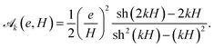
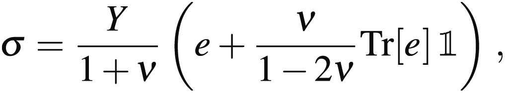
We first turn to the computation of the elastic strain and energy in a hetero-epitaxial nanomembrane where the substrate is supposed to be flat and freestanding. It may correspond to experiments on a freestanding crystalline-sheet substrate or on a thin sheet with very weak interactions with its underlying substrate. We consider a thin film of thickness h on a thin substrate of thickness e, with H = h + e, the membrane thickness, see Fig. 1. The film surface is characterized by its free boundary at z = H(r) where r = (x, y), while the substrate lower surface is located at z = 0. In isotropic elasticity, the displacement e and stress σ tensors are related by32| | 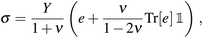 | (1) |
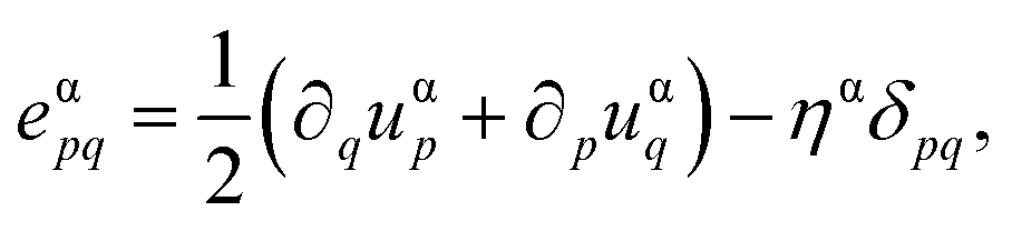
where Y and ν are the Young's modulus and Poisson's ratio of the film and substrate, supposed to be identical at the lowest order. When the interface is coherent, stress arises in the whole system from the lattice mismatch between the film and substrate, that is quantified by the misfit m = 1 − af/as, with af(s) the film (substrate) lattice parameter. Using the reference state defined with the substrate lattice parameter, the strain tensor is 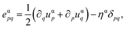 with ηs = 0 in the substrate (α = s) and ηf = m in the film (α = f). Mechanical equilibrium enforces the local relationshipbut the strain state is fully determined by the boundary conditions. We assume that the substrate is freestanding, and that the nanomembrane is embedded in an ultra-high vacuum. As a consequence, both the substrate lower surface and the film upper are supposed to be free of stress (we also neglect surface-stress33). The surface boundary conditions are thencewhere nz is the unit vector in the z direction, and n, the unit vector normal to the film surface. Finally, when the interface is coherent, the displacement u and forces are continuous
| | | u(z = e−) = u(z = e+), | (4a) |
| | | σ·nz(z = e−) = σ·nz(z = e+). | (4b) |
 |
| | Fig. 1 Geometry of a nanomembrane with a film coherently deposited on a thin substrate of finite thickness. | |
The computation of the stress field may be done as a power-law expansion in the small-slope approximation where |∇H| ≪ 1. Its results depend crucially on the level of stress in the zeroth-order flat-film geometry34 where H(r) = H when the system is invariant by translation or rotation in the (x, y) plane. Hence, all the measurable properties such as forces, stress tensor and displacement gradients are independent of x and y, but not necessarily the displacement vector defined only up to an arbitrary reference state. In this geometry, the displacement vector u0 satisfies
| |  | (5) |
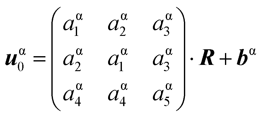
Given the invariance of σ on x and y, Navier eqn (2) projected on the x direction leads to the fact that σxz, and thence exz and ∂u0,x/∂x, are constant both in the film and substrate. Similarly, the projection of (2) on the z-direction leads to a constant σzz and ∂uz/∂z in the film and in the substrate, and to the same conclusion for ∂u0,z/∂x and ∂u0,z/∂y (after differentiation of σzz with respect to x). The general solution for the mechanical equilibrium accounting for the flat geometry is then
| | 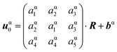 | (6) |
in the film and substrate (α = f or s), where
R = (
x,
y,
z)
T and choosing a reference state symmetric with respect to
x and
y. The stress-free surface boundary conditions
(3a) and
(3b) give
aα4 = −
aα3 while
aα5 = −2
νaα1/(1 −
ν) +
ηα(1 +
ν)/(1 −
ν). We choose a reference state such as
bsi = 0 in the substrate. The continuity relation
(4a) leads to
afi =
asi,
bf1 = 0 while
bf2 = −
me(1 +
ν)/(1 −
ν). At this point, one is left with three unknowns,
as1,
as2 and
as3 that cannot be set by the remaining boundary condition
(4b). Indeed, the Navier equation combined with the invariance along
x and
y leads to the invariance of
σ·
nz along
z. Thence, for a flat film where
n =
nz, if
(3a) and
(3b) are satisfied,
(4b) is automatically satisfied. To go further, we first set
as3 = 0 thanks to an irrelevant rotation of the reference state around the
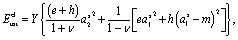
z axis. Then, the solution for equilibrium is found by minimizing the total elastic energy. The latter reads per unit surface
| |  | (7) |
in which a minimum is found for
as1 =
mh/(
e +
h) and
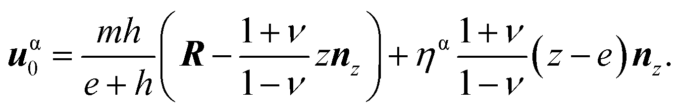
as2 = 0. Eventually, for a flat film, the displacement vector is at equilibrium
| | 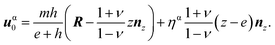 | (8) |
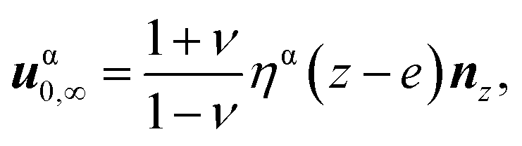
In the limit of a semi-infinite substrate, eqn (8) leads to the known result 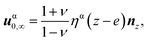 that vanishes in the substrate and displays the Poisson's dilatation in the film. In the opposite limit e → 0, one finds the symmetric case
 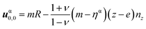 where the film is fully relaxed while the substrate displays the Poisson's dilatation in the opposite direction. In between, the solution (8) quantifies the strain shared between the film and the substrate. Finally, the elastic energy density
  associated with (8) is in the film
| |  | (9) |
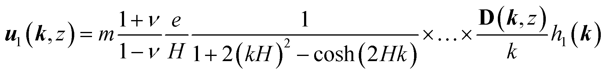
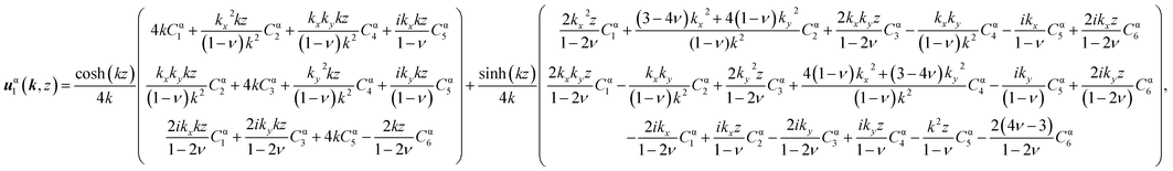
We now turn to the case where the film is corrugated and displays small slopes. Writing H(r) = H + h1(r) with H = 〈H(r)〉, one may find the solution for the displacement vector as an expansion u = u0 + u1 +…, supposing that h1 (in fact |∇h1|) is a small parameter. At equilibrium, u1 may be conveniently found in Fourier space in the x and y directions, with the result given in Table 1.
Table 1 General solution for the displacement vector in a nanomembrane
|
(10) |
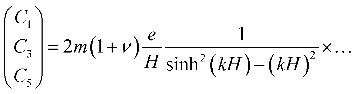
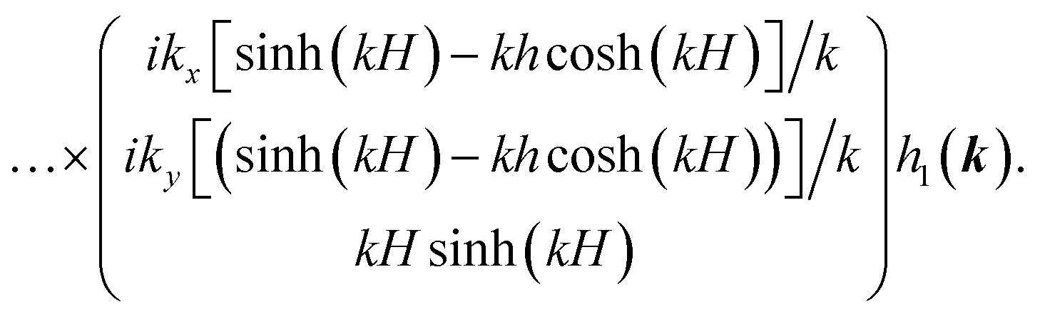
We find there are six unknown Cαis both in the film and substrate, and, contrarily to the semi-infinite case, both ekz and e−kz terms, with the wavevector k and k = |k|. The boundary conditions at the interface (4a) and (4b) give Cfi = Csi ≡ Ci (independent of the film or substrate) for i = 1…6, that lead to uf1 = us1, an identity resulting from the hypothesis of an identical film and substrate elastic constants.† The boundary condition (3a) gives C2 = ikxC5, C4 = ikyC5 and C6 = iν(kxC1 + kyC3)/(1 − ν). Eventually, the surface boundary condition (3b) gives
| | 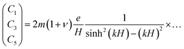 | (11) |
| |  | (12) |
Given this solution for the Cis and thence for u (given explicitly in Appendix), one can compute the elastic energy density on the film surface at z = H(r), that reads  with
with  given in (9) and
| | 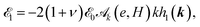 | (13) |
where
| |  | (14) |
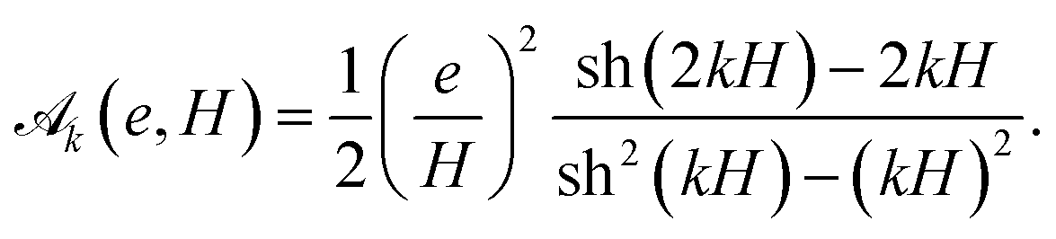
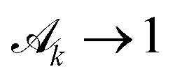
In the limit of a semi-infinite substrate (where e ≫ h and kH ≫ 1), one finds  as expected.35 Otherwise
  describes the influence of strain-sharing and of finite-size effects on elasticity.
3 Dynamical evolution
3.1 Fourier analysis
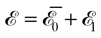
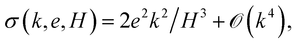
The elastic stress may be relieved by the morphological change of the film free surface when surface diffusion is at work, as described by the Asaro–Tiller–Grinfeld instability.25,26,36 This corresponds to experiments where the film free surface is in contact with vacuum so that the surface diffusion is activated, while the surface diffusion on the lower substrate surface is inhibited, e.g. by contact with porous materials, or occurs on a larger time scale. Mass conservation on the film surface thence enforces the diffusion equation37 ∂h/∂t = DΔsμ where D is the diffusion constant, and Δs, the surface Laplacian. The chemical potential μ is the sum of the elastic energy density on the surface  and of the capillary term γκ, where γ is the surface energy (we neglect here the surface energy anisotropy38) and κ = −(hxx + hyy) is the surface local mean curvature. Given the solution (13), one finds that a modulation of wave-vector k evolves in the linear approximation as h1(k, t) = eik·r+σt with
| |  | (15) |
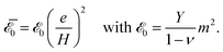
in units of the space and time scales  and t0 = l04/(Dγ).
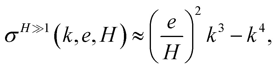
We plot in Fig. 2, the resulting growth rate as a function of k and e for different membrane thicknesses H. It is first noted that σ can be either strongly increased or lowered depending on finite-size effects (ruled by H) and strain sharing (ruled by e/H). To quantify this, we compute the maximum of σ for a given e and H, that occurs at (kmax, σmax), see Fig. 3. We take as a reference, the infinite-substrate limit σ∞(k) = k3 − k4 for which σ∞max = 27/256 ≃ 0.105 and k∞max = 3/4 (this limit occurs when both H ≫ 1 and e/H ≃ 1, i.e. e ≫ h). This limit is already nearly achieved when H = 10 and when strain sharing vanishes (e/H ≃ 1). By decreasing the membrane thickness, one finds a ten-fold increase in σmax for H = 1 without strain sharing (σmax ≃ 1.15 when e/H ≃ 1) and a 103-fold increase for H = 0.1 (σmax ≃ 101 when e/H ≃ 1). Hence, for a given e/H, the maximum growth rate increases with H, showing the a priori counter-intuitive influence of finite-size effects that enforce a faster relaxation for a thinner membrane. Conversely, for a given H, the growth rate significantly decreases when strain sharing occurs (i.e. when e/H decreases from 1). For H = 10, one finds respectively σmax = 0.105, 9.5 × 10⁻⁴ and 1.0 × 10⁻⁶ for e/H = 1, 1/2 and 1/10. Similarly, for H = 0.1, one finds respectively σmax = 101, 6.27 and 1.0 × 10⁻² for e/H = 1, 1/2 and 1/10. Therefore, the stronger strain-sharing is (i.e. the lower e/H is), the slower the instability occurs, as the less strained the system is.
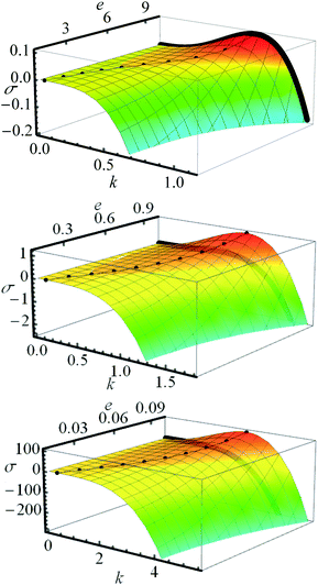 |
| | Fig. 2 Growth rate σ(k, e, H) for H = 10 (top), H = 1 (middle) and H = 0.1 (bottom). The black thick solid line represents the reference σ∞(k) corresponding to the semi-infinite substrate limit. The dots locate the maximum value (kmax, σmax) of σ(k, e, H) for given e and H. | |
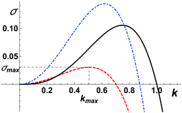 |
| | Fig. 3 (Dashed red line) Typical growth rate σ(k, e, h) of the morphological instability as a function of its wavevector k when strain sharing is at work, for e/H = 5/6 and H = 6 in dimensionless units; (dot-dashed blue line) the same curve for e/H = 1/2 and H = 2/3; (black solid line) infinite substrate limit σ∞(k). | |
The second conclusion regarding σ(k, e, H) is the variation of the maximum wavelength kmax as a function of finite-size and strain-sharing effects. We find, see Fig. 2, that for a given H, kmax decreases when strain-sharing increases (i.e. when e/H decreases) while, for a given e/H, kmax increases when finite-size effects increase (i.e. when H decreases). Numerically, we find for H = 10, respectively kmax = 0.75, 0.19 and 0.032 for e/H = 1, 1/2 and 1/10, while for H = 0.1, kmax = 3.18, 1.58 and 0.32 for e/H = 1, 1/2 and 1/10. The decreases of kmax with strain-sharing corroborate the fact that the film is globally less strained in this case. Conversely, the increase in kmax with finite-size effects is consistent with the increase in σ, signaling the increase in the surface strain in this case. Globally, even if the variation of kmax with e/H and H is quantitatively less pronounced than for σmax, it is nonetheless significant and leads to variations that are expected to be important in experimental systems.
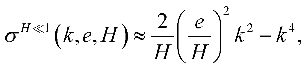
We note that for given strain-sharing and finite-size effects, the growth rate eqn (15) always displays a positive maximum so that the morphological instability should always occur (we neglect here the influence of wetting effects that can lead to the existence of a critical thickness,35 in order to focus solely on the influence of strain-sharing and finite-size effects). Indeed, for given e/H and H, we find at low-k ‡ while σ(k, e, H) ≈ −k4 at large k.§ Another interesting limit is the thin-membrane limit (when H ≪ 1), where
 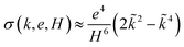 with
with ![[k with combining tilde]](https://www.rsc.org/images/entities/i_char_006b_0303.gif) = k/kt and kt = e/H3/2. When both e and H are of order ε, kmax diverges as
= k/kt and kt = e/H3/2. When both e and H are of order ε, kmax diverges as  while σmax behaves as 1/ε2.
3.2 Real-space analysis
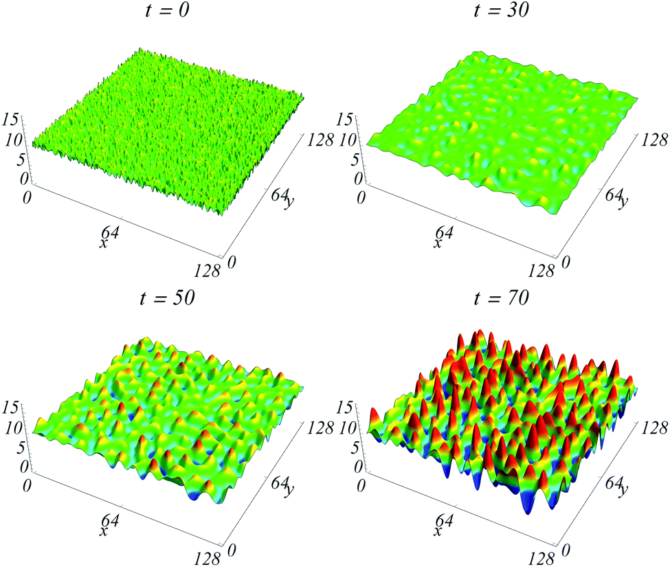
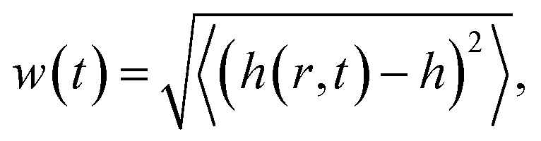
We now investigate an evolution that shows experimental systems where the ATG instability is at work, with the deposition of a film of a given thickness, followed by instability during a subsequent annealing. The initial condition is a film with a given thickness h on top of a thin substrate of thickness e, with an additional surface roughness on the film free surface. The latter stands for the deposition noise and thermal fluctuations, that is described here by an initial white noise with an amplitude of one monolayer. We then study surface diffusion during annealing. In this case, the surface is not characterized by a unique wave-vector, but may be decomposed as the sum of different Fourier modes with equal amplitude at t = 0 (describing a white noise). We consider only the linear regime of the surface diffusion equation (that is relevant in the small-slope approximation) where elasticity is given at first order in h by eqn (13). Hence, the different Fourier modes evolve independently following eqn (15), starting with equal amplitude, and evolving with different growth rates. We expect the fastest growing mode kmax to mainly rule the long-time behavior,39 nevertheless within a time-scale where the linear regime applies, i.e. when the surface slope remains small.
The resulting typical evolution on top of a membrane is shown in Fig. 4. We characterize the surface geometry with the length-scale λ that can be related to the average wave-vector
| | 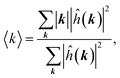 | (16) |
(where the summation runs over the different Fourier modes), thanks to
λ = 2π/〈
k〉. On the other hand, the dynamical evolution may be associated with a characteristic time
τ, defined through the surface roughness
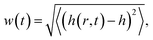
by
w(
t =
τ) =
ew(
t = 0). This time-scale rules the initial exponential increase in the surface roughness in the linear regime. In addition, these scales can be compared to the scales associated with the fastest growing mode
kmax,
λmax = 2π/
kmax and
τmax =
αN/
σmax where
accounts for the initial random noise uniformly distributed on
N Fourier modes.
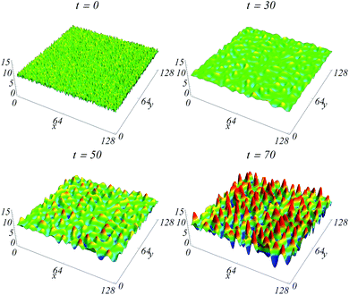 |
| | Fig. 4 Evolution of the film surface h(x, y, t) for H = 10 and e/H = 0.9. | |
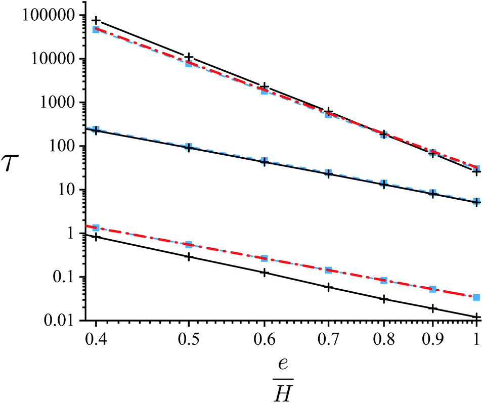
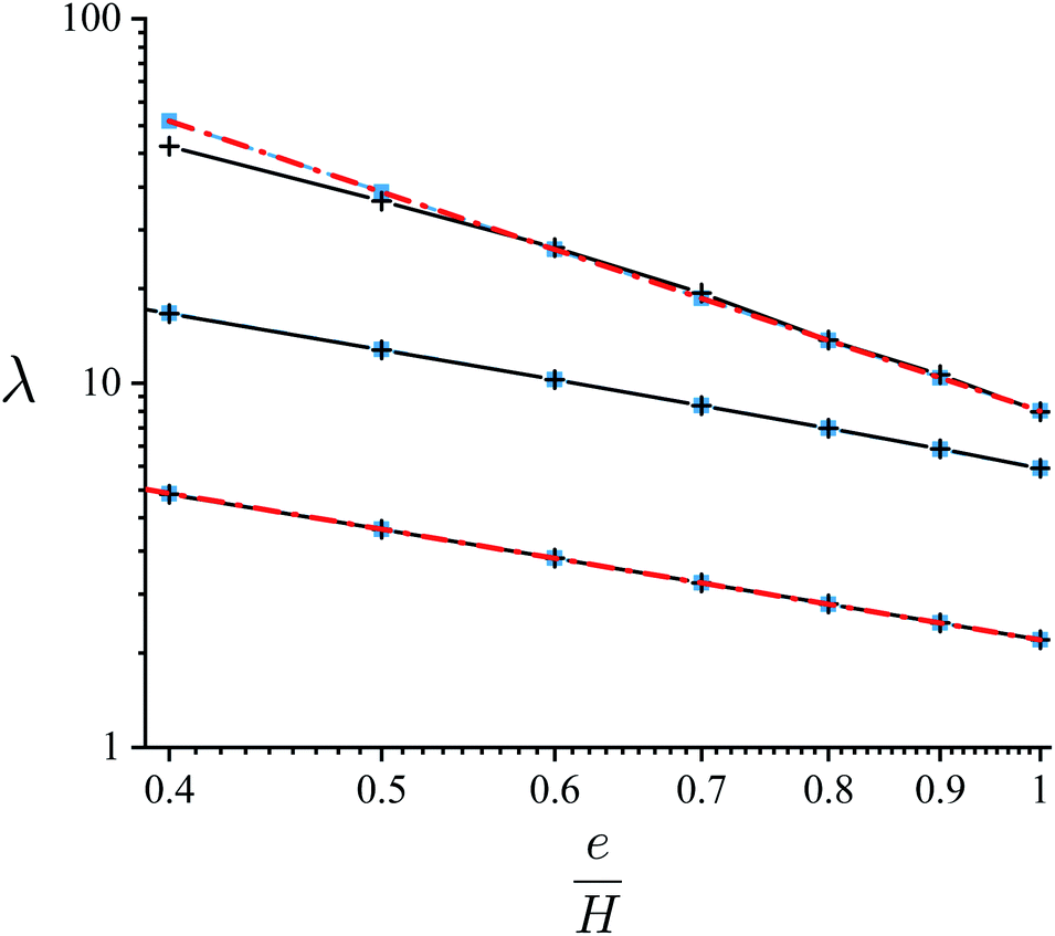
We plot in Fig. 5 and 6, the resulting characteristic scales for H = 100, 1 and 0.1. It is noteworthy that the typical time scale τ displays huge variations as a function of strain sharing and finite-size effects. For a given H, it shows a 104 (respectively 102) increase when e/H decreases from 1 to 0.4 for H = 100 (resp. 0.1), describing a strong slowdown of the instability evolution. This sensitivity is naturally related to the decrease in the global strain with strain-sharing, as described above for the growth rate σ. But we also find that τ decreases strongly when H decreases for a given e/H: we find e.g. a decrease from 30 down to 0.012 in between H = 100 and 0.1 for e/H = 1. This reveals the counter-intuitive result of these finite-effects, coherently related to their influence on the growth rate σ: a thinner membrane leads to a much faster surface dynamics, and the acceleration of the instability. Similarly, the typical wave-length of the instability is also ruled by strain-sharing and finite-size effects, but with a lower amplitude, see Fig. 6. The increase in λ when e/H decreases is again related to the decrease in the global strain but with a factor at most around 3 to 4, while its decrease when H decreases is also related to the counter-intuitive finite-size effects. In addition, we find that the resulting length and time scales λ and τ are very well approximated by λmax and τmax, showing that the fastest growing mode is quickly driving the surface dynamics. It is nonetheless not a perfect approximation, especially for τ and at low thickness H where the maximum of σ(k) is less sharp.
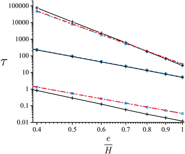 |
| | Fig. 5 Characteristic time-scale τ (black solid line) as a function of the strain-sharing ratio e/H and numerical estimate (dashed-blue line) for (top curve) H = 100, (middle) H = 1 and (bottom) H = 0.1. For the top and bottom curves, analytical approximation τmax (dot-dashed red line) respectively for H ≫ 1 and H ≪ 1. | |
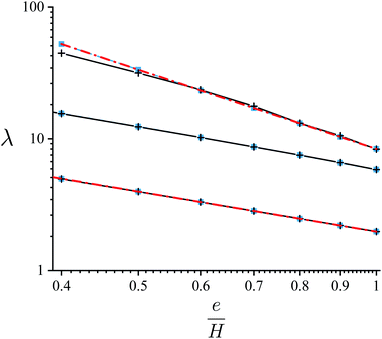 |
| | Fig. 6 Characteristic length-scale λ (black solid line) for large time t (nevertheless within the small-slope approximation) as a function of the strain-sharing ratio e/H and numerical estimate (dashed-blue line) for (top curve) H = 100, (middle) H = 1 and (bottom) H = 0.1. For the top and bottom curves, analytical approximation τmax (dot-dashed red line) respectively for H ≫ 1 and H ≪ 1. | |
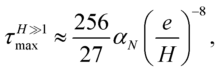
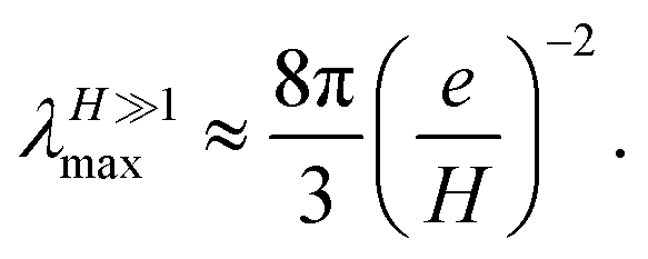
To get some analytical insights on these evolutions, we find that the previous results can be well approximated in some limits, see Fig. 5 and 6. When finite-size effects vanish, i.e. for H ≫ 1, one finds
| | 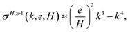 | (17) |
that can be maximized, giving the approximate
| |  | (18a) |
| |  | (18b) |
These approximations are plotted in Fig. 5 and 6 and do indeed perfectly capture the numerical estimate of τmax and λmax, and approximate well the global time and length scales τ and λ. In the other limit of strong finite-size effects, i.e. for H ≪ 1, we find the Laurent series
| | 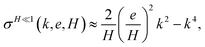 | (19) |
leading to the approximates
| | 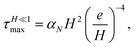 | (20a) |
| | 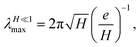 | (20b) |
that again approximate well both the numerical estimates
τmax and
λmax, and more importantly the global values
τ and
λ, see
Fig. 5 and
6. Hence, these power-laws characterize well the strong variations of
τ and
λ as a function of strain-sharing and finite-size effects. Finally, we also plot the results of the intermediate case for
H = 1 in
Fig. 5 and
6, that is characterized here by
τH=1 = 5.6(
e/
H)
−4.0 while
λH=1 ≈ 6.0(
e/
H)
−1.0 with exponents close to the
H ≪ 1 limit. Note that in all cases, as
t0 scales as
l04, it is natural to find here that the dependence of
τ on
e/
H is as
λ4.
4 Conclusion
As a conclusion, we have investigated the influence of strain-sharing and finite-size effects on the morphological instability at work in strained nano-membranes. We have shown that geometric parameters can tune the nanomembrane surface dynamics and rule either its strong acceleration in thin nanomembranes, or its strong inhibition when strain is significantly shared. This theoretical study may serve as a guide to rationalize and control experiments on such systems. One of its natural extension concerns the study of sandwiched film/substrate/film geometries where corrugations grow on both sides of the NM. The initial linear evolution in such geometries should correspond to the results of the present analysis, while correlations between the NM both sides are expected to arise at non-linear order and are currently under investigation.
5 Appendix
The full solution for the displacement vector at first order in the surface slope is eventually| |  | (21) |
with| | Dx = i2kx{k![[thin space (1/6-em)]](https://www.rsc.org/images/entities/char_2009.gif) sinh(kz) × … × [((2ν − 1)H − z)sinh(kH) + kHzcosh(kH)] − cosh(kz)[(k2Hz − 2(ν − 1))sinh(kH) + 2(ν − 1)kHcosh(kH)]} sinh(kz) × … × [((2ν − 1)H − z)sinh(kH) + kHzcosh(kH)] − cosh(kz)[(k2Hz − 2(ν − 1))sinh(kH) + 2(ν − 1)kHcosh(kH)]} | (22) |
and a symmetric definition for Dy, while| | | Dz = −k{sinh(kH) × … × [sinh(kz)(kz − k2Hz − 2(ν − 1)) − 2cosh(kz)(kz − 2(ν − 1)kH)] + 2kHcosh(kH)[(2ν − 1)sinh(kz) + kzcosh(kz)]} | (23) |
Conflicts of interest
There are no conflicts to declare.
Acknowledgements
The authors thank Isabelle Berbezier for fruitful discussions.
References
- Q. Guo, Z. Di, M. G. Lagally and Y. Mei, Mater. Sci. Eng., R, 2018, 128, 1 CrossRef , ISSN 0927-796X.
- G. Huang and Y. Mei, Small, 2018, 14, 1703665 CrossRef PubMed.
- M. Huang, C. Boone, M. Roberts, D. E. Savage, M. G. Lagally, N. Shaji, H. Qin, R. Blick, J. A. Nairn and F. Liu, Adv. Mater., 2005, 17, 2860 CrossRef CAS , ISSN 1521-4095.
- L. Zhang, E. Ruh, D. Grützmacher, L. Dong, D. J. Bell, B. J. Nelson and C. Schönenberger, Nano Lett., 2006, 6, 1311 CrossRef CAS PubMed.
- D. Y. Khang, H. Jiang, Y. Huang and J. A. Rogers, Science, 2006, 311, 208 CrossRef CAS PubMed.
- A. Malachias, Y. Mei, R. K. Annabattula, C. Deneke, P. R. Onck and O. G. Schmidt, ACS Nano, 2008, 2, 1715 CrossRef CAS PubMed.
- D. M. Paskiewicz, B. Tanto, D. E. Savage and M. G. Lagally, ACS Nano, 2011, 5, 5814, DOI:10.1021/nn201547k.
- J. N. Aqua, L. Favre, A. Ronda, A. Benkouider and I. Berbezier, Cryst. Growth Des., 2015, 15, 3399, DOI:10.1021/acs.cgd.5b00485.
- C. Xu, X. Wu, G. Huang and Y. Mei, Adv. Mater. Technol., 2019, 4, 1800486 Search PubMed.
- S. A. Scott and M. G. Lagally, J. Phys. D: Appl. Phys., 2007, 40, R75 CrossRef CAS , http://stacks.iop.org/0022-3727/40/i=4/a=R01.
- J. A. Rogers, M. G. Lagally and R. G. Nuzzo, Nature, 2011, 477, 45, DOI:10.1038/nature10381.
- I. Berbezier, J. N. Aqua, M. Aouassa, L. Favre, S. Escoubas, A. Gouyé and A. Ronda, Phys. Rev. B: Condens. Matter Mater. Phys., 2014, 90, 035315, DOI:10.1103/PhysRevB.90.035315.
- T. David, J. Aqua, K. Liu, L. Favre, A. Ronda, M. Abbarchi, J. Claude and I. Berbezier, Sci. Rep., 2018, 8, 2891 CrossRef PubMed , https://www.nature.com/articles/s41598-018-21299-9.
- A. Ghaffari, A. Hosseini, X. Xu, D. Kwong, H. Subbaraman and R. T. Chen, Opt. Express, 2010, 18, 20086 CrossRef CAS PubMed.
- J. Viventi, D. H. Kim, L. Vigeland, E. S. Frechette, J. A. Blanco, Y. S. Kim, A. E. Avrin, V. R. Tiruvadi, S. W. Hwang, A. C. Vanleer, D. F. Wulsin, K. Davis, C. E. Gelber, L. Palmer, J. Van der Spiegel, J. Wu, J. Xiao, Y. Huang, D. Contreras, J. A. Rogers and B. Litt, Nat. Neurosci., 2011, 14, 1599, DOI:10.1038/nn.2973.
- M. Ying, A. P. Bonifas, N. Lu, Y. Su, R. Li, H. Cheng, A. Ameen, Y. Huang and J. A. Rogers, Nanotechnology, 2012, 23, 344004 CrossRef , http://stacks.iop.org/0957-4484/23/i=34/a=344004.
- H. Fang, H. A. Bechtel, E. Plis, M. C. Martin, S. Krishna, E. Yablonovitch and A. Javey, Proc. Natl. Acad. Sci. U. S. A., 2013, 110, 11688 CrossRef CAS , ISSN 0027-8424.
- H. Zhou, J. H. Seo, D. M. Paskiewicz, Y. Zhu, G. K. Celler, P. M. Voyles, W. Zhou, M. G. Lagally and Z. Ma, Sci. Rep., 2013, 3, 1291 CrossRef.
- J. S. Vorobyova, A. B. Vorob'ev, V. Y. Prinz, A. I. Toropov and D. K. Maude, Nano Lett., 2015, 15, 1673 CrossRef CAS PubMed.
- G. Li, E. Song, G. Huang, Q. Guo, F. Ma, B. Zhou and Y. Mei, Adv. Funct. Mater., 2018, 28, 1801448 CrossRef.
- R. Pan, Q. Guo, J. Cao, G. Huang, Y. Wang, Y. Qin, Z. Tian, Z. An, Z. Di and Y. Mei, Nanoscale, 2019, 11(36), 16844, 10.1039/C9NR05189A.
- M. Vutukuru, J. W. Christopher, C. Pollock, D. J. Bishop and A. K. Swan, J. Microelectromech. Syst., 2019, 28, 550 CAS.
- B. L. T. Rosa, C. A. Parra-Murillo, T. Chagas, A. J. Garcia Junior, P. S. S. Guimarães, C. Deneke, R. Magalhães-Paniago and A. Malachias, ACS Appl. Nano Mater., 2019, 2, 4655 CrossRef CAS.
- J. N. Aqua and X. Xu, Surf. Sci., 2015, 639, 20 CrossRef CAS , http://www.sciencedirect.com/science/article/pii/S0039602815001016.
- R. J. Asaro and W. A. Tiller, Metall. Trans., 1972, 3, 1789 CrossRef CAS.
- M. A. Grinfeld, Sov. Phys. Dokl., 1986, 31, 831 Search PubMed.
- K. Liu, I. Berbezier, T. David, L. Favre, A. Ronda, M. Abbarchi, P. W. Voorhees and J. N. Aqua, Phys. Rev. Mater., 2017, 1(5), 053402, DOI:10.1103/PhysRevMaterials.1.053402.
- K. Liu, I. Berbezier, L. Favre, A. Ronda, M. Abbarchi, P. Donnadieu, P. W. Voorhees and J. N. Aqua, Nanoscale, 2019, 11, 7798–7804 RSC.
- M. Huang, P. Rugheimer, M. G. Lagally and F. Liu, Phys. Rev. B: Condens. Matter Mater. Phys., 2005, 72, 085450, DOI:10.1103/PhysRevB.72.085450.
- H. J. Kim-Lee, D. E. Savage, C. S. Ritz, M. G. Lagally and K. T. Turner, Phys. Rev. Lett., 2009, 102(22), 226103, DOI:10.1103/PhysRevLett.102.226103.
- G. Vastola, V. B. Shenoy and Y. W. Zhang, ACS Nano, 2012, 6, 3377, DOI:10.1021/nn3003983.
-
L. Landau and E. Lifchitz, Theory of Elasticity, USSR Academy of Sciences, Moscow, USSR, 1986 Search PubMed.
- M. S. Levine, A. A. Golovin, S. H. Davis and P. W. Voorhees, Phys. Rev. B: Condens. Matter Mater. Phys., 2007, 75, 205312, DOI:10.1103/PhysRevB.75.205312.
- K. Liu, I. Berbezier, L. Favre, A. Ronda, T. David, M. Abbarchi, P. Gaillard, T. Frisch, B. Croset and J. N. Aqua, Phys. Rev. Mater., 2019, 3, 023403 CrossRef CAS.
- J. N. Aqua, T. Frisch and A. Verga, Phys. Rev. B: Condens. Matter Mater. Phys., 2007, 76, 165319, DOI:10.1103/PhysRevB.76.165319.
- B. J. Spencer, P. W. Voorhees and S. H. Davies, J. Appl. Phys., 1993, 73, 4955 CrossRef CAS.
- B. J. Spencer, P. W. Voorhees and S. H. Davis, Phys. Rev. Lett., 1991, 67, 3696, DOI:10.1103/PhysRevLett.67.3696.
- J. N. Aqua, A. Gouyé, T. Auphan, T. Frisch, A. Ronda and I. Berbezier, Appl. Phys. Lett., 2011, 98, 161909, DOI:10.1063/1.3576916.
- X. Xu, J. N. Aqua and T. Frisch, J. Phys.: Condens. Matter, 2012, 24, 045002 CrossRef CAS PubMed , http://stacks.iop.org/0953-8984/24/i=4/a=045002.
Footnotes |
| † This was also proven in the semi-infinite substrate case. |
| ‡ Note that the k → 0 and H → ∞ limits do not commute. |
| § Subsequently, there exists k+ such as σ < 0 for k > k+, and the instability will occur only if no lateral finite-size effect occurs, i.e. only if L > 2π/k+. |
|
| This journal is © The Royal Society of Chemistry 2020 |
Click here to see how this site uses Cookies. View our privacy policy here. 
 Open Access Article
 This Open Access Article is licensed under a Creative Commons Attribution-Non Commercial 3.0 Unported Licence
 *
*
 with ηs = 0 in the substrate (α = s) and ηf = m in the film (α = f). Mechanical equilibrium enforces the local relationship
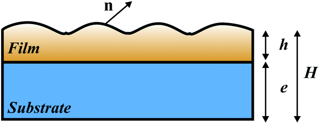
 that vanishes in the substrate and displays the Poisson's dilatation in the film. In the opposite limit e → 0, one finds the symmetric case
 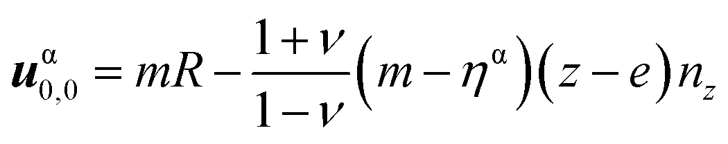 where the film is fully relaxed while the substrate displays the Poisson's dilatation in the opposite direction. In between, the solution (8) quantifies the strain shared between the film and the substrate. Finally, the elastic energy density
 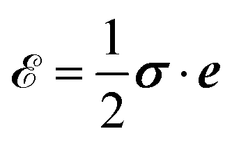 associated with (8) is in the film
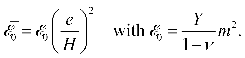

 with
with  given in (9) and
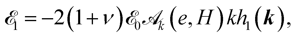
 as expected.35 Otherwise
  describes the influence of strain-sharing and of finite-size effects on elasticity.
 and of the capillary term γκ, where γ is the surface energy (we neglect here the surface energy anisotropy38) and κ = −(hxx + hyy) is the surface local mean curvature. Given the solution (13), one finds that a modulation of wave-vector k evolves in the linear approximation as h1(k, t) = eik·r+σt with
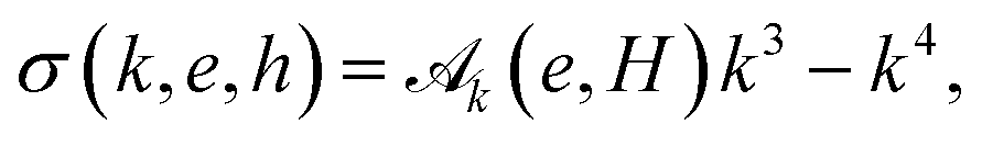
 and t0 = l04/(Dγ).


 ‡ while σ(k, e, H) ≈ −k4 at large k.§ Another interesting limit is the thin-membrane limit (when H ≪ 1), where
 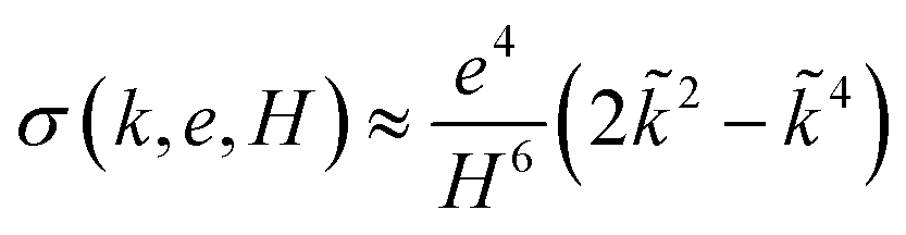 with
with  while σmax behaves as 1/ε2.
 by w(t = τ) = ew(t = 0). This time-scale rules the initial exponential increase in the surface roughness in the linear regime. In addition, these scales can be compared to the scales associated with the fastest growing mode kmax, λmax = 2π/kmax and τmax = αN/σmax where
  accounts for the initial random noise uniformly distributed on N Fourier modes.