
 Open Access Article
 This Open Access Article is licensed under a Creative Commons Attribution-Non Commercial 3.0 Unported Licence
The effect of in situ nitrogen doping on the oxygen evolution reaction of MXenes†
Yi
Tang
 ,
Chenhui
Yang
,
Yapeng
Tian
,
Yangyang
Luo
,
Xingtian
Yin
and
Wenxiu
Que
*
,
Chenhui
Yang
,
Yapeng
Tian
,
Yangyang
Luo
,
Xingtian
Yin
and
Wenxiu
Que
*
Electronic Materials Research Laboratory, Key Laboratory of the Ministry of Education & International Center for Dielectric Research, Shaanxi Engineering Research Center of Advanced Energy Materials and Devices, School of Electronic & Information Engineering, Xi'an Jiaotong University, Xi'an 710049, Shaanxi, People's Republic of China. E-mail: wxque@mail.xjtu.edu.cn
First published on 11th February 2020
Abstract
The development of non-noble metal electrocatalysts with high performance for the oxygen evolution reaction (OER) is highly desirable but still faces many challenges. Herein, we report a facile and controllable strategy to fabricate N-doped titanium carbide flakes (Ti3C1.8N0.2 and Ti3C1.6N0.4) using an in situ nitrogen solid solution, followed by an etching process. The introduction of nitrogen is beneficial to the Ti3C1.6N0.4 flakes for more exposed active sites, accelerated charge transfer upon an electrochemical reaction, and improved wettability for more accessible sites. As a result, the as-obtained Ti3C1.6N0.4 catalyst exhibits enhanced electrocatalytic properties for OER, which include a small ηonset of 245.8 mV, low Tafel slope of 216.4 mV dec−1, and relatively good catalytic stability. The present work not only deepens the understanding of in situ N-doped MXene electrocatalysts, but also provides a guideline for the preparation of other N-doped MXene-based hybrid materials for other renewable energy applications.
1. Introduction
Due to the increasing energy consumption and serious pollution, we are eager to develop sustainable energy sources to lessen the reliance on fossil fuels. Renewable energy storage and conversion techniques such as fuel cells, metal–air batteries, and water splitting systems, which have high efficiency, excellent reliability, and zero pollution, are promising alternatives for traditional fossil fuels.1,2 The oxygen evolution reaction (OER) is one of the most fundamental and important reactions in the above-mentioned renewable energy technologies. However, this reaction is currently constrained by sluggish kinetics and large overpotential; thus, efficient electrocatalysts are in demand. To date, precious metal-based catalysts, such as IrO2 and RuO2, are the best due to their optimum binding with essential intermediates, but their applicability is hampered due to their high cost and scarcity.3 Hence, tremendous efforts have been devoted to search for alternative electrocatalysts constructed from low-cost and earth-abundant elements to efficiently conduct OER with a minimum overpotential.4MXenes, as an emerging family of two-dimensional (2D) transition metal carbide, nitride and carbonitride nanomaterials, have attracted significant attention. Their formula is Mn+1XnTz, where M is an early transition metal, X represents C and/or N, and T represents surface termination groups (–O, –OH, and –F).5,6 Moreover, MXenes can be achieved by the selective etching of the A element from the MAX phases, where A is a group IIIA or IVA element. For the sake of simplicity, MXenes are usually expressed as Mn+1Xn. MXenes are regarded as promising supporting materials by virtue of their high electrical conductivity, unique hydrophilicity, relatively good chemical stability, and high surface area as well as their ultralow work function.7 In particular, in the field of electrocatalysis, MXenes ensure fast electron transport during electrochemical reactions and may alter the electrophilicity of the active centers of the catalysts, thus tuning the catalytic properties of multicomponent catalyst systems. Ti3C2, as a promising member of MXenes, is commonly used in the field of electrocatalysis. Nevertheless, it should be mentioned here that the inherent catalytic activity of Ti3C2 is relatively low, which may be due to its low number of catalytic active sites and the tendency to stack.
To improve its catalytic activity, one commonly used strategy is to combine Ti3C2 with materials that have high catalytic activity. On the basis of this principle, Ti3C2-based hybrid electrocatalysts, such as Ni1−xFexPS3@Ti3C2,8 NiCoS/Ti3C2Tx,9 FeNi-LDH/Ti3C2-MXene,10 MoS2/Ti3C2-MXene@C,11 and Ti3C2Tx-CoBDC,7 appear constantly and exhibit superb OER/HER activity. Additionally, the chemical doping of heteroatoms is an effective strategy to improve the electrochemical properties of materials. Notably, nitrogen-containing functional groups can significantly enhance the electrochemical performance of the materials by increasing the electrical conductivity for faster ion transport and improvement in surface wettability for more active sites.12,13 For example, our previous studies have demonstrated that nitrogen-doped Ti3C2 nanosheets possess superior electrochemical performance.14–16 Jiang and co-workers have demonstrated that the synthesized nitrogen-doped ultrathin carbon nanosheets (NCNs) with an ultrathin sheet structure, ultrahigh specific surface area, and rich edge defects exhibit extraordinary trifunctional activity toward ORR, OER, and HER.17 Sheng et al. have shown that the developed self-supported nitrogen-doped carbon hydrogel films also have outstanding OER activity.18 Moreover, dual-atom (N and P) co-functionalized porous carbon materials possess superior electrocatalytic activity.19,20
In this work, nitrogen-doped few-layered Ti3C2 nanosheets with different nitrogen concentrations (Ti3C1.8N0.2 and Ti3C1.6N0.4) have been synthesized using an in situ nitrogen solid solution, followed by an HCl and LiF-assisted etching process. The results prove that the introduction of nitrogen is beneficial for electrical conductivity and wettability. Besides, the fresh Ti3C1.6N0.4 electrocatalysts with relatively higher electrical conductivity, better wettability, and more active sites are favorable for OER activity. This work expands the understanding of the effect of in situ nitrogen doping on the catalytic performance of MXenes and also contributes to the preparation of N-doped MXene hybrid structures with higher catalytic activity.
2. Results and discussion
A previous work has indicated that nitrogen can be easily introduced into the Ti3C2 flakes by achieving the corresponding nitrogen solid solution (Ti3AlC1.8N0.2 and Ti3AlC1.6N0.4 powders).15 Additionally, Ti3C2, Ti3C1.8N0.2 and Ti3C1.6N0.4 flakes are obtained using a wet-chemical method, as presented in Fig. S1,† and the atomic structure of the Ti3C1.6N0.4 phase is schematically presented in Fig. 1. It can be seen that a certain number of nitrogen atoms dispersed into the Ti3C1.6N0.4 atom structure not only provide abundant active sites, but also effectively improve the electrical conductivity and wettability, thus enhancing the electrocatalytic activity. All of these advancements endow Ti3C1.6N0.4 with enhanced electrocatalytic performance for OER in an alkaline solution (4OH−![[left over right harpoons]](https://www.rsc.org/images/entities/char_21cb.gif) 2H2O(l) + O2(g) + 4e−).
2H2O(l) + O2(g) + 4e−).
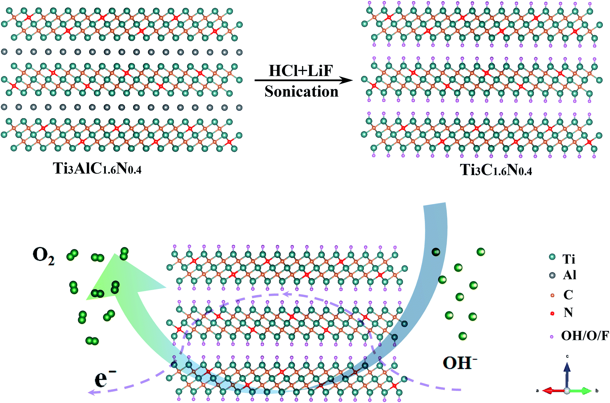 | ||
| Fig. 1 Schematic illustration of the fabrication of the Ti3C1.6N0.4 electrocatalyst with an atomic structure. | ||
Actually, the flexible and free-standing films produced by the vacuum filtration of few-layered MXene flake suspensions are beneficial for the characterization of their own features. Scanning electron microscopy (SEM) and transmission electron microscopy (TEM) were employed to observe the morphological and microstructural properties of the Ti3C2, Ti3C1.8N0.2, and Ti3C1.6N0.4 films. From the top-view SEM images (Fig. 2a–c), similar morphologies with considerable wrinkles can be found on the surfaces of the Ti3C2, Ti3C1.8N0.2, and Ti3C1.6N0.4 films. Fig. 2d shows the cross-sectional view SEM image of the Ti3C1.6N0.4 film. It can be clearly seen that the flexible Ti3C1.6N0.4 film with a well-aligned layered structure self-assembles from the Ti3C1.6N0.4 flakes via the vacuum filtration method, which is consistent with previous results.6,15 Further observation of the Ti3C1.6N0.4 flakes shows that they have a lateral size of several microns and thickness of several nanometers, as shown in Fig. 2e. The corresponding EDS elemental mappings (Fig. 2f) reveal that Ti, C, and especially N are evenly distributed in the Ti3C1.6N0.4 film, which is also good evidence for the successful introduction of nitrogen. X-ray diffraction (XRD) was employed to examine the crystal structures of the three ceramic powders and films (Fig. S2† and 2g). It can be seen that the XRD patterns of the three ceramic powder samples show similar characteristic peaks, which can be assigned to the diffraction peaks of Ti3AlC2 (PDF card #52-0875). Moreover, with the increase in the nitrogen doping content, the typical peaks of (104) gradually shift to the right, indicating the successful introduction of nitrogen (Fig. S2†). The XRD patterns of the three films are similar, indicating that the three films have similar crystal structures. However, the inset shows that the characteristic peaks of the (002) plane of the Ti3C1.8N0.2 and Ti3C1.6N0.4 films shift to a lower angle, which confirms the enhancement in the d-spacing caused by nitrogen doping. Besides, the shift in the typical (002) peak of the Ti3C1.6N0.4 film is relatively inconspicuous compared with that of the Ti3C1.8N0.2 film, which may be due to different types of nitrogen. The above-mentioned results demonstrate that nitrogen has been successfully introduced into the Ti3C1.6N0.4 flakes.
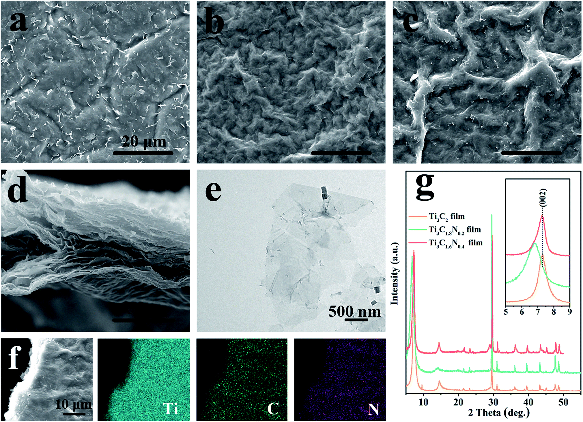 | ||
| Fig. 2 Top-view SEM images of the Ti3C2 (a), Ti3C1.8N0.2, (b) and Ti3C1.6N0.4 (c) films. (d) A cross-sectional view SEM image of the Ti3C1.6N0.4 film. (e) The TEM image of the few-layered Ti3C1.6N0.4 flakes. (f) SEM image and the corresponding elemental mappings of Ti, C, and N in the Ti3C1.6N0.4 film. (g) XRD patterns of the Ti3C2, Ti3C1.8N0.2, and Ti3C1.6N0.4 films; the inset shows the diffraction peaks at around (002) for the three films. | ||
To detect the chemical composition and bonding states of the as-synthesized samples, X-ray photoelectron spectroscopy (XPS) was subsequently performed for these samples. The survey region (0–1200 eV) shown in Fig. 3a indicates the presence of the common peaks of C 1s, N 1s, O 1s, F 1s, and Ti 2p, manifesting the presence of the Ti3C2, Ti3C1.8N0.2, and Ti3C1.6N0.4 films together with –O, –OH, and –F terminated groups due to the use of an HCl + LiF aqueous solution. Specifically, additional N 1s peaks for the Ti3C1.8N0.2 and Ti3C1.6N0.4 films further indicate the successful introduction of nitrogen into these films, which is in good agreement with the EDS results. The elemental composition via XPS presented in Table S1† reveals that the concentrations of N 1s are 3.76 at% and 5.72 at% for Ti3C1.8N0.2 and Ti3C1.6N0.4, respectively. More nitrogen atoms improve the electronegativity of Ti3C1.6N0.4, which is beneficial for the electron-withdrawing effect. To further analyze the location of nitrogen, the deconvolutions of the N 1s region spectra are shown in Fig. 3b. The three peaks located at 397.1 eV, 399.8 eV, and 401.9 eV correspond to the N–Ti (nitride), N-5 (pyrrolic nitrogen), and N–Q (quaternary nitrogen) species.21 The presence of the N–Ti peaks provides confirmation of the in situ substitution of C atoms with N atoms in the octahedral interstice of the Ti3C1.8N0.2 structure. The N–Ti bond in the N 1s spectra is consistent with the Ti–N peak centered at 457.3 eV in the Ti 2p spectra (Fig. S3†). In particular, the Ti3C1.6N0.4 structure exhibits more N species, including of N–Ti, N-5, N–Q species, and an extra N-6 (pyridinic nitrogen) bond at 398.5 eV.22 In addition, the concentrations of the different nitrogen species in the two samples are quantified based on the integrated peak areas and presented in Table S2.† It can be seen that N–Ti is the dominant N species in the Ti3C1.8N0.2 (52.46 at%) and Ti3C1.6N0.4 (61.75 at%) samples; in contrast, compared with that of the Ti3C1.8N0.2 sample, the loading of N-5 in the Ti3C1.6N0.4 sample diminishes markedly accompanied by an increase in N–Q and the emergence of N-6. Based on the above-mentioned results and previously reported findings,19,23–27 the properties of the various N bonds are as follows: (1) the N–Ti and N-5 species have little effect on the improvement in the electrocatalytic performance. (2) N–Q, where N is bonded with three C neighbors, provides a larger contribution to enhance the electrocatalytic activity. (3) N-6, where N is incorporated into a six-membered heterocyclic ring, brings about electron–donor properties, which may be the main reason for the enhanced OER activity. Therefore, higher contents of both N–Q (13.52 at%) and N-6 (2.88 at%) in the Ti3C1.6N0.4 sample endow it with higher catalytic activity.
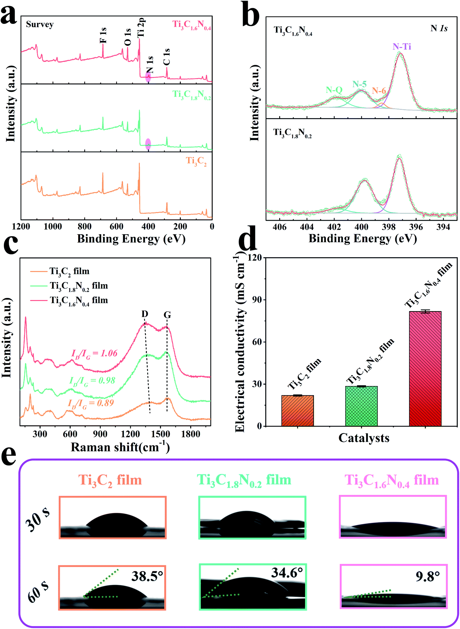 | ||
| Fig. 3 (a) XPS spectra of the Ti3C2, Ti3C1.8N0.2, and Ti3C1.6N0.4 films. (b) High-resolution XPS N 1s spectra of the Ti3C1.8N0.2 and Ti3C1.6N0.4 films. Raman spectra (c) and electrical conductivities (d) of the three films. (e) The contact angles of the dynamic 1 M KOH electrolyte for the three films. | ||
Fig. 3c shows the Raman spectra of the three films and the peaks are consistent with those reported in our previous works.6,15 In particular, the characteristic peak at ∼1364 cm−1 is related to the D-band and is attributed to the disordered graphite formed by the defects in carbon-based materials. The other characteristic peak located at ∼1549 cm−1 is related to the G-band, which corresponds to the vibration of the sp2-hybridized carbon atoms in a 2D hexagonal lattice. The values of ID/IG calculated from the intensities of the D-band and G-band peaks were 0.89 for Ti3C2, 0.98 for Ti3C1.8N0.2, and 1.06 for Ti3C1.6N0.4. A higher value of ID/IG implies the insertion of N atoms and indicates the formation of more disorder and defects (heterogeneous atoms and vacancies) in the carbon structure, which contribute to additional active sites for the improvement in catalytic activity.28 In addition, the distinct redshift in the D peak of the Ti3C1.6N0.4 sample indicates the restoration of the conjugate structure after the nitrogen atoms are doped into the graphitic lattice. As indexed in the Raman spectra, the rich defect sites observed among the crystal lattices of Ti3C1.6N0.4 can tune its electronic and surface properties and thus optimize the adsorption energies of the electrochemical catalysis steps.
It has been reported that the structural defects caused by heterogeneous atom doping in materials have a significant influence on their electrical properties.29,30 The electrical conductivities of the films are shown in Fig. 3d and S5.† As expected, doping nitrogen atoms is indeed helpful to improve the conductivity of the sample. The electrical conductivities were 81.74 ± 1.16 mS cm−1 for Ti3C1.6N0.4, 28.42 ± 0.43 mS cm−1 for Ti3C1.8N0.2, and 21.90 ± 0.39 mS cm−1 for Ti3C2. It is worth mentioning that Ti3C1.6N0.4 has the highest electrical conductivity among the three measured films, which can result in efficient electron transfer during the electrocatalytic reaction process. In addition, the contact angle of a dynamic 1 M KOH aqueous electrolyte was measured for the three films. As illustrated in Fig. 3e, the introduction of nitrogen has a positive effect on wettability. Obviously, the Ti3C1.6N0.4 film shows a smaller contact angle of 9.8° with the electrolyte, which indicates that Ti3C1.6N0.4 is more hydrophilic compared with Ti3C1.8N0.2 and Ti3C2. Better hydrophilicity can improve the accessibility of the catalyst to the electrolyte and increase the available sites, thus leading to enhanced catalytic performance.
To obtain further insights in the effect of nitrogen doping on electrocatalytic performance, we studied the fresh Ti3C2, Ti3C1.8N0.2 and Ti3C1.6N0.4 flakes towards OER in a 1 M KOH alkaline solution in a typical three-electrode system, where the potential was compensated by solution resistance (iRs). Before the electrochemical measurements, the electrode underwent an activation treatment using several linear sweep voltammetry (LSV) until a stable curve was achieved. Fig. 4a presents the LSV curves of the Ti3C2, Ti3C1.8N0.2 and Ti3C1.6N0.4 electrodes at a scan rate of 5 mV s−1. The bare carbon fiber paper (CFP) substrate showed no catalytic activity. In contrast, the fresh Ti3C2 flakes showed minimal catalytic activity, while the fresh Ti3C1.8N0.2 flakes exhibited enhanced catalytic activity. Apparently, the fresh Ti3C1.6N0.4 flakes showed the best OER activity, which may be because of the synergistic effect of more exposed active sites, higher electrical conductivity, and better wettability due to the introduction of nitrogen. However, it is also worth mentioning here that N doping improves activity, but it can result in reduced stability of the material structure at the same time, as reflected in the literature.31 The corresponding Tafel plots are also provided to investigate the OER kinetics of the electrocatalysts. As shown in Fig. 4b, the Tafel slopes are 243.4 mV dec−1, 234.7 mV dec−1, and 216.4 mV dec−1 for the fresh Ti3C2, Ti3C1.8N0.2, and Ti3C1.6N0.4 catalysts, respectively. Obviously, the Ti3C1.6N0.4 flakes exhibited the smallest Tafel slope, indicating the best OER catalytic kinetics.
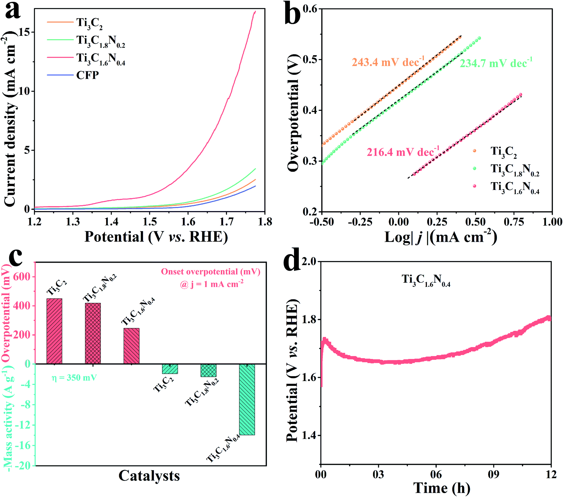 | ||
| Fig. 4 (a) LSV curves of the Ti3C2, Ti3C1.8N0.2, and Ti3C1.6N0.4 electrocatalysts and bare CFP substrate. (b) Tafel plots of the three electrocatalysts. (c) Comparison of the Ti3C2, Ti3C1.8N0.2, and Ti3C1.6N0.4 electrocatalysts at an onset overpotential of 1.0 mA cm−2 and mass activity of η = 350 mV. (d) Durability tests of the Ti3C1.6N0.4 electrocatalyst at a constant current density of 10 mA cm−2 for 12 h. | ||
The overpotential is an important index to evaluate the electrocatalytic performance of the as-fabricated electrocatalysts. The onset overpotential is defined as the overpotential when the current density reaches 1.0 mA cm−2. As shown in Fig. 4c, the onset overpotentials (ηonset) are 449.0, 418.7, and 245.8 mV for the fresh Ti3C2, Ti3C1.8N0.2, and Ti3C1.6N0.4 electrocatalysts, respectively. The smaller ηonset of the Ti3C1.6N0.4 electrocatalyst implies its superior electrocatalytic activity, which means that a low additional potential is required to sustainably drive an electrochemical reaction from its reversible potential. In addition, the mass activity, which is the current normalized by the loaded mass of a catalyst, is currently gaining importance for the evaluation of nanostructured electrocatalysts for HER. The mass activity of the Ti3C1.6N0.4 electrocatalyst at η = 350 mV was 14.0 A g−1, which was 7.7-fold and 5.6-fold higher than those of the Ti3C2 and Ti3C1.8N0.2 electrocatalysts, respectively. The much higher mass activity (A g−1) at the same overpotential (η) further demonstrates that Ti3C1.6N0.4 is the best among the three electrocatalysts. Besides indispensable higher activity, the excellent stability of electrocatalysts toward OER is another critical factor for their practical application. The long-term durability of the electrocatalyst was estimated via chronopotentiometry at 10 mA cm−2. It can be observed from Fig. 4d that the Ti3C1.6N0.4 electrode shows a fluctuating potential curve over a period of 12 h. The Ti3C1.6N0.4 electrode requires ∼1.68 V to afford an OER current density of 10 mA cm−2. The initial high potential is due to incomplete electrode activation and partial wettability of the electrode surface. However, it is worth mentioning that the continuous increase in potential after 9.0 h is due to the reduced stability of the Ti3C1.6N0.4 flakes, which might be due to the combined effects of the prolonged alkaline environment, released oxygen and electricity.
To gain a better understanding of the superior electrocatalytic activity of the Ti3C1.6N0.4 catalyst, the electrochemically active surface area (ECSA) of the catalyst was estimated by determining the electrochemical double layer capacitance (Cdl) since ECSA is generally proportional to Cdl.32 A small potential range from 1.17 V to 1.27 V without an apparent faradaic reaction was selected to calculate Cdl (Fig. S4†). Thus, the final Cdl was obtained by extracting the slope of the linear relationship between the current density difference and the scan rate. As shown in Fig. 5a, the Cdl values are 2.51 mF cm−2 for the Ti3C2 catalyst, 3.09 mF cm−2 for Ti3C1.8N0.2, and 6.08 mF cm−2 for Ti3C1.6N0.4. Compared with Ti3C2 and Ti3C1.8N0.2, Ti3C1.6N0.4 has a larger Cdl value, indicating that it has more active sites, which are useful for catalyzing OER.
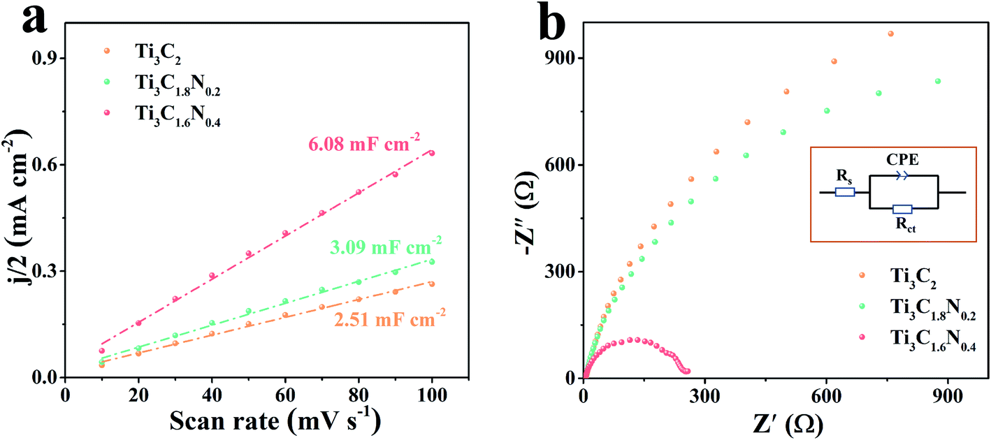 | ||
| Fig. 5 (a) Double-layer capacitances (Cdl) of the Ti3C2, Ti3C1.8N0.2, and Ti3C1.6N0.4 electrocatalysts. (b) Nyquist plots of the above-mentioned electrocatalysts measured at a potential of 1.62 V vs. RHE; the inset shows the equivalent electrical circuit image. | ||
It is widely accepted that the OER performance in the electrolyte is dominated by ionic and transport resistances.33 As shown in Fig. 5b, to further probe the possible reason for the enhanced performance of the Ti3C1.6N0.4 catalyst, the corresponding Nyquist plots at 1.62 V have been recorded to pinpoint the resistance during experimental OER. The equivalent circuit model is leveraged to obtain the values of the ionic and charge transfer resistances of the OER catalyst in a 1 M KOH electrolyte (inset of Fig. 5b). In a high frequency region, the diameter of the semicircular arc is related to the charge transfer resistance (Rct), which originates from the ion transfer across the entire interface between the electrode material and the electrolyte accessible area. The real-axis intercept of the impedance spectra in the high frequency region corresponds to the internal resistance (Rs) of the test device. The simulated Rs, Rct, and CPE values of the Ti3C2, Ti3C1.8N0.2, and Ti3C1.6N0.4 catalysts are shown in Table S3.† Notably, the Ti3C1.6N0.4 catalyst has relatively small Rs (3.12 ohm) compared to the Ti3C2 (Rs = 4.88 ohm) and Ti3C1.8N0.2 (Rs = 5.39 ohm) catalysts, indicating a decrease in the internal resistance and thus a better electronic response. Furthermore, the Ti3C1.6N0.4 catalyst exhibits the lowest Rct (279.20 ohm), which can reduce the potential barrier to drive the current transport across the catalyst. To this end, the resistances acquired from the Nyquist plots of the three catalysts reveal that the Ti3C1.6N0.4 catalyst with significantly lower impedance markedly enhances OER kinetics. In a word, the improved OER activity of the Ti3C1.6N0.4 catalyst is ascribed to the synergetic effect of high electrical conductivity, good wettability, and more exposed active sites.
3. Conclusions
In summary, we have successfully synthesized N-doped titanium carbide nanosheets (Ti3C1.8N0.2 and Ti3C1.6N0.4) using an in situ nitrogen doping solid solution method with the merits of facile and controllable features. The results indicate that the introduction of nitrogen can increase exposed active sites and improve electrical conductivity and wettability, thus enhancing the electrocatalytic activity. As a result, the Ti3C1.6N0.4 catalyst with a higher nitrogen concentration exhibits better catalytic properties for OER, including a small ηonset of 245.8 mV, low Tafel slope of 216.4 mV dec−1, and relatively good catalytic stability. The enhanced electrocatalytic activity of the Ti3C1.6N0.4 catalyst is attributed to the synergetic effects of abundant catalytic active sites, high conductivity, low resistance, and good wettability. This work contributes to the field of in situ nitrogen-doped MXene electrocatalysts and also provides a guideline for the preparation of other N-doped MXene-based hybrid materials for renewable energy applications.4. Experimental section
Detailed experimental information is available in the ESI.†Conflicts of interest
There are no conflicts to declare.Acknowledgements
This work was supported by the National Natural Science Foundation of China (61774122), the Science and Technology Developing Project of Shaanxi Province (2015KW-001), and the 111 Project of China (B14040). The SEM and TEM work was conducted at the International Center for Dielectric Research, Xi'an Jiaotong University. We also thank Dr Jiamei Liu at the Instrument Analysis Center of Xi'an Jiaotong University for her assistance with the X-ray photoelectron spectrometer (XPS, ESCALAB Xi+, Thermo Fisher Scientific, USA) analysis.References
- T. Zhang, Y. Zhu and J. Y. Lee, J. Mater. Chem. A, 2018, 6, 8147–8158 RSC.
- F. Lyu, Q. Wang, S. M. Choi and Y. Yin, Small, 2019, 15, 1804201 CrossRef PubMed.
- M. Tahir, L. Pan, F. Idrees, X. Zhang, L. Wang, J.-J. Zou and Z. L. Wang, Nano Energy, 2017, 37, 136–157 CrossRef CAS.
- A. Eftekhari, Materials Today Energy, 2017, 5, 37–57 CrossRef.
- J. Pang, R. G. Mendes, A. Bachmatiuk, L. Zhao, H. Q. Ta, T. Gemming, H. Liu, Z. Liu and M. H. Rummeli, Chem. Soc. Rev., 2018, 48, 72–133 RSC.
- C. Yang, Y. Tang, Y. Tian, Y. Luo, Y. He, X. Yin and W. Que, Adv. Funct. Mater., 2018, 28, 1705487 CrossRef.
- L. Zhao, B. Dong, S. Li, L. Zhou, L. Lai, Z. Wang, S. Zhao, M. Han, K. Gao, M. Lu, X. Xie, B. Chen, Z. Liu, X. Wang, H. Zhang, H. Li, J. Liu, H. Zhang, X. Huang and W. Huang, ACS Nano, 2017, 11, 5800–5807 CrossRef CAS PubMed.
- C.-F. Du, K. N. Dinh, Q. Liang, Y. Zheng, Y. Luo, J. Zhang and Q. Yan, Adv. Energy Mater., 2018, 8, 1801127 CrossRef.
- H. Zou, B. He, P. Kuang, J. Yu and K. Fan, ACS Appl. Mater. Interfaces, 2018, 10, 22311–22319 CrossRef CAS PubMed.
- M. Yu, S. Zhou, Z. Wang, J. Zhao and J. Qiu, Nano Energy, 2018, 44, 181–190 CrossRef CAS.
- X. Wu, Z. Wang, M. Yu, L. Xiu and J. Qiu, Adv. Mater., 2017, 29, 1607017 CrossRef PubMed.
- W. Zhou, J. Jia, J. Lu, L. Yang, D. Hou, G. Li and S. Chen, Nano Energy, 2016, 28, 29–43 CrossRef CAS.
- J. Duan, S. Chen, M. Jaroniec and S. Z. Qiao, ACS Catal., 2015, 5, 5207–5234 CrossRef CAS.
- C. Yang, W. Que, X. Yin, Y. Tian, Y. Yang and M. Que, Electrochim. Acta, 2017, 225, 416–424 CrossRef CAS.
- C. Yang, Y. Tang, Y. Tian, Y. Luo, M. Faraz Ud Din, X. Yin and W. Que, Adv. Energy Mater., 2018, 8, 1802087 CrossRef.
- Y. Tang, J. Zhu, W. Wu, C. Yang, W. Lv and F. Wang, J. Electrochem. Soc., 2017, 164, A923–A929 CrossRef CAS.
- H. Jiang, J. Gu, X. Zheng, M. Liu, X. Qiu, L. Wang, W. Li, Z. Chen, X. Ji and J. Li, Energy Environ. Sci., 2019, 12, 322–333 RSC.
- S. Chen, J. Duan, M. Jaroniec and S.-Z. Qiao, Adv. Mater., 2014, 26, 2925–2930 CrossRef CAS PubMed.
- H. Jiang, Y. Wang, J. Hao, Y. Liu, W. Li and J. Li, Carbon, 2017, 122, 64–73 CrossRef CAS.
- J. Zhang, L. Qu, G. Shi, J. Liu, J. Chen and L. Dai, Angew. Chem., 2016, 128, 2270–2274 CrossRef.
- Y. Wen, T. E. Rufford, X. Chen, N. Li, M. Lyu, L. Dai and L. Wang, Nano Energy, 2017, 38, 368–376 CrossRef CAS.
- C. Lei, Y. Wang, Y. Hou, P. Liu, J. Yang, T. Zhang, X. Zhuang, M. Chen, B. Yang, L. Lei, C. Yuan, M. Qiu and X. Feng, Energy Environ. Sci., 2018, 12, 149–156 RSC.
- W. Niu, S. Pakhira, K. Marcus, Z. Li, J. L. Mendoza-Cortes and Y. Yang, Adv. Energy Mater., 2018, 8, 1800480 CrossRef.
- M. Liu, X. Lu, C. Guo, Z. Wang, Y. Li, Y. Lin, Y. Zhou, S. Wang and J. Zhang, ACS Appl. Mater. Interfaces, 2017, 9, 36146–36153 CrossRef CAS PubMed.
- X. Cui, S. Yang, X. Yan, J. Leng, S. Shuang, P. M. Ajayan and Z. Zhang, Adv. Funct. Mater., 2016, 26, 5708–5717 CrossRef CAS.
- W. Niu, L. Li, X. Liu, N. Wang, J. Liu, W. Zhou, Z. Tang and S. Chen, J. Am. Chem. Soc., 2015, 137, 5555–5562 CrossRef CAS PubMed.
- Z. Luo, S. Lim, Z. Tian, J. Shang, L. Lai, B. MacDonald, C. Fu, Z. Shen, T. Yu and J. Lin, J. Mater. Chem., 2011, 21, 8038–8044 RSC.
- Y. Tian, L. Xu, J. Bao, J. Qian, H. Su, H. Li, H. Gu, C. Yan and H. Li, J. Energy Chem., 2019, 33, 59–66 CrossRef.
- J. Ye, H. Zhao, W. Song, N. Wang, M. Kang and Z. Li, J. Power Sources, 2019, 412, 606–614 CrossRef CAS.
- C. Xu, S. Peng, C. Tan, H. Ang, H. Tan, H. Zhang and Q. Yan, J. Mater. Chem. A, 2014, 2, 5597–5601 RSC.
- F. Du, H. Tang, L. Pan, T. Zhang, H. Lu, J. Xiong, J. Yang and C. Zhang, Electrochim. Acta, 2017, 235, 690–699 CrossRef CAS.
- Q. Liang, L. Zhong, C. Du, Y. Luo, Y. Zheng, S. Li and Q. Yan, Nano Energy, 2018, 47, 257–265 CrossRef CAS.
- Y. Pei, Y. Yang, F. Zhang, P. Dong, R. Baines, Y. Ge, H. Chu, P. M. Ajayan, J. Shen and M. Ye, ACS Appl. Mater. Interfaces, 2017, 9, 31887–31896 CrossRef CAS PubMed.
Footnote |
| † Electronic supplementary information (ESI) available. See DOI: 10.1039/c9na00706g |
| This journal is © The Royal Society of Chemistry 2020 |