
 Open Access Article
 This Open Access Article is licensed under a Creative Commons Attribution-Non Commercial 3.0 Unported Licence
Advanced technologies for the fabrication of MOF thin films
Chiara
Crivello†
 a,
Semih
Sevim†
b,
Octavio
Graniel
a,
Carlos
Franco
b,
Salvador
Pané
*c,
Josep
Puigmartí-Luis
*abde and
David
Muñoz-Rojas
*a
a,
Semih
Sevim†
b,
Octavio
Graniel
a,
Carlos
Franco
b,
Salvador
Pané
*c,
Josep
Puigmartí-Luis
*abde and
David
Muñoz-Rojas
*a
aLaboratoire des Matérieaux et do Génie Physique (LMGP), Grenoble, France. E-mail: david.munoz-rojas@grenoble-inp.fr
bInstitute of Chemical and Bioengineering, ETH Zurich, Vladimir Prelog Weg 1, 8093 Zurich, Switzerland
cMulti-Scale Robotics Lab (MSRL), Institute of Robotics and Intelligent Systems (IRIS), ETH Zurich, Tannenstrasse 3, 8092 Zurich, Switzerland
dDepartament de Ciència dels Materials i Química Física, Institut de Química Teòrica i Computacional, 08028 Barcelona, Spain
eICREA, Pg. Lluís Companys 23, 08010 Barcelona, Spain
First published on 28th September 2020
Abstract
Metal–organic framework (MOF) thin films represent a milestone in the development of future technological breakthroughs. The processability of MOFs as films on surfaces together with their major features (i.e. tunable porosity, large internal surface area, and high crystallinity) is broadening their range of applications to areas such as gas sensing, microelectronics, photovoltaics, and membrane-based separation technologies. Despite the recent attention that MOF thin films have received, many challenges still need to be addressed for their manufacturing and integrability, especially when an industrial scale-up perspective is envisioned. In this brief review, we introduce several appealing approaches that have been developed in the last few years. First, a summary of liquid phase strategies that comprise microfluidic methods and supersaturation-driven crystallization processes is described. Then, gas phase approaches based on atomic layer deposition (ALD) are also presented.
 Chiara Crivello | Chiara Crivello received her degree in Materials Chemistry at the University of Studies of Palermo, Italy (UNIPA, 2018). She is currently doing her PhD in Materials Science at the Laboratoire des Matériaux et du Génie Physique (LMGP) in Grenoble, France. Her current research interests include synthesis of MOF thin films and their properties. |
 Salvador Pané | Salvador Pané is a Professor of Materials for Robotics and co-director of the Multi-Scale Robotics Lab (MSRL) of ETH Zürich from 2020. He received his PhD in chemistry from the UB (Barcelona) in 2008, then he became a postdoctoral researcher in 2008 and a senior scientist at MRSL in 2013. In 2012 and 2017, he was awarded the highly competitive ERC-StG and ERC-CoG grants, respectively. His research is focused on bridging materials science, chemistry, and electrochemistry with small-scale robotics for biomedical and environmental applications. |
 Josep Puigmartí-Luis | Josep Puigmartí-Luis (Artés, 1978) obtained his PhD at the Materials Science Institute in Barcelona and did his postdoctoral research at ETH Zürich, where in 2009 he was made a Postdoctoral ETH Fellow. His research interests include the synthesis and controlled assembly of functional organic and inorganic materials (in solution and at surfaces) via microfluidic technologies. In 2015, he was awarded an ERC starting grant to study, control, and understand the self-assembly processes of metal–organic crystalline materials. In 2019, he was appointed an ICREA Research Professor. |
 David Muñoz-Rojas | David Muñoz-Rojas obtained his degree in Organic Chemistry at the Instituto Químico de Sarrià (IQS, Barcelona, 1999) and his PhD in Materials Science (2004) at the Instituto de Ciencia de Materiales de Barcelona. Thereafter, he worked as a postdoc at the Laboratoire de Réactivité et Chimie des Solides in Amiens, the Research Centre for Nanoscience and Nanotechnology in Barcelona and at the University of Cambridge. He is currently a CNRS researcher at Laboratoire des Matériaux et du Génie Physique in Grenoble. His research focuses on using and developing cheap and scalable chemical approaches for the fabrication of novel functional materials for electronic and optoelectronic applications. |
MOFs: moving from the bulk towards thin films
Metal–organic frameworks (MOFs) are porous hybrid crystalline materials consisting of metal-based nodes connected through organic ligands.1 The intrinsic porous architecture of MOFs yields large surface areas, from a few hundreds of m2 g−1 to above ten thousand m2 g−1,2–4 resulting in excellent adsorption capabilities.5,6 Furthermore, the plethora of MOF lattice structures available and their exquisite chemical tunability, both associated with the ample menu of metal nodes and organic linkers, make them multifunctional platforms with tailorable capabilities.7–9 MOFs are conventionally obtained as polycrystalline micro-powders with very low processability. However, their integration onto surfaces and devices is highly desired for a large variety of applications, e.g. volatile organic compound (VOC) sensors, membranes for water desalination, or organic field effect transistors, to mention only a few.10–14 In this vein, MOF thin films are attractive systems for unprecedented technological breakthroughs as they can endow surfaces with enticing properties and advanced functionalities while minimizing the amount of material used.15,16 However, the general lack of understanding of growth mechanisms and the poor structural control have limited their widespread application in emerging products and/or existing markets. Also, it is necessary to say that the use of MOF thin films in applications is still not a completely mature field.17In general, MOF thin films are prepared by the following three different approaches:
(I) Layer-by-layer (LbL) methods
These techniques are based on surface chemistry, where a self-assembled monolayer (SAM) is used as a template for the growth of MOF crystals. In this case, MOFs grow as a result of sequential reactions between the organic ligand and the inorganic nodes. Frequently, the reactions are conducted in conventional glassware (non-confined conditions) where turbulent environments dominate. Additionally, a washing step is required between each reaction to eliminate surplus reagents. Consequently, while the orientation and thickness of MOF thin films can be controlled to some extent with LbL methods, these protocols are time-consuming and labour intensive.15,18–20(II) Electrically driven synthesis
This approach consists of inducing the formation of MOFs on electrodes by means of electrochemical reactions or electrophoresis. There are basically two electrochemical strategies. One consists of using a metal anode as the source of metal nodes to form the MOF. In this approach, the metal oxidizes and the resulting ions react with the ligands present in the electrolyte, thus leading to the formation of a MOF film on the electrode. A second approach consists of inducing the cathodic electrodeposition of the MOF by placing both the metal salts and the ligands in the electrolyte. In this method, electrogenerated hydroxyl ions at the cathode (due to the hydrogen evolution reaction) deprotonate the organic ligands, which ultimately leads to the formation of the MOF film. MOF films can also be formed on substrates by means of electrophoretic deposition of colloidally stable charged MOF nanoparticles.21,22 Nevertheless, the success of this methodology is strongly determined by the intrinsic properties of the building blocks (e.g. electron/proton conductivity), a feature that has limited its widespread application to different MOF systems. Note that only a limited number of MOFs have been processed by electrically driven deposition approaches.16,23,24(III) Casting of MOF powders
The dispersion of MOF crystals synthesized by solvothermal methods is deposited over substrates using classical casting techniques such as spray coating, spin coating, and/or drop-casting.17 Even though these techniques can be applied to cast a broad number of MOFs, the quality of the films obtained is, in general, low. Besides, oriented thin films are extremely difficult to achieve due to the poor control of the nucleation and crystal growth offered by these approaches.As all of these methods have been extensively reviewed in the past,15,19,25–30 this minireview will focus exclusively on two of the most recent approaches reported to obtain MOF thin films: liquid phase approaches operating under high surface-to-volume ratio conditions (i.e. microfluidic technologies and blade coating) and gas phase techniques (Fig. 1). As it will be discussed in the following sections, both the liquid phase and gas phase methods allow for the synthesis of MOF thin films where not only the orientation of the crystal faces can be controlled but also the film thickness. Moreover, gas phase approaches do not require the use of solvents, which makes them quite enticing for the fabrication of microelectronic devices.5
 | ||
| Fig. 1 Illustration showing the different approaches discussed in this work. | ||
Liquid phase approaches
In nature, single crystals with complex and hierarchical structures can be readily obtained from solution by allocating the building block units to a desired place at the right time (i.e. spatiotemporal assembly).31 However, despite the vast number of methods performed in the liquid phase to produce MOF thin films,15,19,25–30 control over the crystal domain size and shape of MOFs is still missing. Accordingly, new liquid phase approaches featuring spatiotemporal control of the building blocks during MOF synthesis have been recently considered (vide infra). In this vein, microfluidic technologies have gained considerable attention in the scientific community as they are able to control the spatiotemporal diffusion of building blocks;32 avoid turbulent environments, which can lead to precipitation, and thus, to uncontrolled crystal growth; and, furthermore, they can mimic nature's confined environments in the laboratory with the ambition of ultimately controlling MOF crystal growth. In this section, the discussion will mainly be focussed on MOF thin film fabrication protocols where liquid phase approaches have been exploited. Two different categories are considered: continuous-flow microfluidic synthesis and supersaturation-driven crystallization processes in confined micro- and nanoscale environments.Continuous-flow microfluidic synthesis
Continuous-flow microfluidic devices can lead to a paradigm shift in material synthesis.33 The laminar flow regime established inside microfluidic devices offers advanced synthetic conditions where constant spatiotemporal mass transport of reagents can be guaranteed.33,34 In a microfluidic device, the mixing of reagents only occurs through diffusion (following Fick's law), a feature that has paved the way to developing approaches for MOF thin film synthesis, and, in particular, for membrane fabrication.18,34The microfluidic synthesis of MOF membranes was first reported by Nair et al. in 2014,35 who developed a method, known as interfacial microfluidic membrane processing (IMMP), where polymeric hollow fibres were used to control the reaction–diffusion area during the synthesis of a prototypical MOF, i.e. zeolitic imidazolate framework-8 (ZIF-8, zinc 2-methylimidazolate). They showed that the use of hollow fibres enables spatial control during ZIF-8 growth, which leads to the controlled fabrication of ZIF-8 membranes in the inner or at the outer surface of the fibre. These membranes could be subsequently used as molecular sieving agents. Additionally, the same group has recently shown that the thickness of the ZIF-8 membranes can be controlled employing the IMMP approach.36 In this research, for example, 5 μm thick ZIF-8 membranes could be easily obtained by performing an initial heating ramp, and engineering the pore size of the membranes. Increasing both the pore size and the temperature enhanced the diffusion of reagents and their nucleation rate, respectively, features that enabled the growth of thinner ZIF-8 membranes. Furthermore, the long-term stability and improved permeation performance of these thin ZIF-8 membranes were also demonstrated.37
Additionally, Kharul and coworkers have shown that the IMMP method can also be conducted when low-boiling-point solvents are considered during MOF synthesis. This aspect is key as it enables straightforward removal of solvents, and hence mild activation of the produced MOF membranes. In their study, the authors showed the formation of both ZIF-8 and Hong Kong University of Science and Technology-1 (HKUST-1, copper(II) 1,3,5-benzenetricarboxylate) membranes on either side of the hollow fibre by controlling the positioning of metal ions and ligand precursors with respect to the polymeric hollow fibre (Fig. 2a and b).38
 | ||
| Fig. 2 (a) Schematic illustration of the interfacial microfluidic synthesis of HKUST-1 membranes either at the inner or outer surface of the polymeric hollow fibres. (b) SEM images showing HKUST-1 films synthesized using the methodology described in (a). (a and b) Reproduced from ref. 38 with permission from The Royal Society of Chemistry. (c) Schematic representation of the experimental steps followed to produce the ultrathin ZIF-8 membranes inside the polymeric hollow fibres via microwave assisted seeding and the microfluidic-based secondary growth method. (d and e) SEM images of the ZIF-8 membrane. (c–e). Reproduced from ref. 39 with permission from Elsevier B.V., copyright 2018. | ||
Recently, Jeong et al. introduced an approach employing polymeric hollow fibres where ultrathin ZIF-8 membranes were obtained by combining microwave-assisted seeding with microfluidic-based secondary growth.39 As shown in Fig. 2c, after saturating the fibre pores with metal ions, the ligand precursor solution was injected inside the hollow fibre under microwave heating to generate a densely-packed seed layer. Subsequently, a growth solution composed of the two precursors was injected and flowed until ultrathin ZIF-8 films (ca. 800 nm) were obtained (Fig. 2d and e).
This confined synthetic strategy of MOF thin films inside capillaries (or fibres) was previously considered employing a LbL approach. In this case the authors demonstrated the formation of a homochiral MOF thin film, i.e. Cu2(D-cam)2P (D-cam = (1R,3)-(+)-camphorate; L-cam = (1S,3R)-( )-camphorate; P = dabco and bipy).40
While in previous research physical barriers (i.e. polymeric hollow fibres) are used to control and/or define the reaction area of precursors, recently Puigmartí-Luis and coworkers exploited the controlled diffusion of precursors inside microfluidic channels to generate MOF thin films with spatiotemporal control (Fig. 3). In this investigation, Sevim et al. used a reactive substrate (i.e. Cu2O) from which smooth and densely-packed HKUST-1 thin films could be readily generated. This method, known as in-flow MOF lithography, enabled unprecedented control during MOF thin film synthesis (Fig. 3b and c). For example, the authors demonstrated that good control over the reaction time as well as over the diffusion of precursors onto the reactive Cu2O substrate was key to achieve compositional gradients of HKUST-1 thin films (Fig. 3d and e). In this pioneering approach, the authors clearly demonstrated that microfluidics can also play a crucial role in surface chemistry, where spatiotemporal control during the synthesis of a functional material can be easily established.41
 | ||
| Fig. 3 (a) Schematic illustration of the in-flow MOF lithography method. (b) TEM cross-section image showing a densely-packed HKUST-1 film synthesized over a Cu2O coated glass substrate. (c) Schematic representation of the time required to obtain compositionally graded HKUST-1 (i.e. spatiotemporal controlled synthesis of a MOF film onto a surface). (d and e) SEM images of a graded HKUST-1 thin film. Note that the compactness of the HKUST-1 thin film varies throughout the width of the microchannel. Reproduced from ref. 41 with permission from Wiley-VCH Verlag GmbH & Co., copyright 2019. | ||
Supersaturation driven crystallization processes
Besides the continuous-flow microfluidic approaches, several other strategies involving confined fluidic conditions have been recently introduced to fabricate MOF thin films (vide infra). In this context, confined spaces featuring high surface-to-volume ratios are being used to accomplish ultimate control over MOF crystal growth. Recently, Giri and coworkers have reported a nanofluidic approach to achieve high-aspect-ratio HKUST-1 crystals.42 A precursor solution of HKUST-1 was confined in nanofluidic channels via capillary action, and then controlled crystallization was induced by heating and evaporating the solvent under a vacuum (Fig. 4a). According to their observations, the crystals initially grew perpendicularly to the surface (i.e. along the channel height), and then parallel to it until they filled the channel width, and, subsequently, along the channel length (Fig. 4b and c), hence yielding high aspect ratio HKUST-1 crystals (Fig. 4d).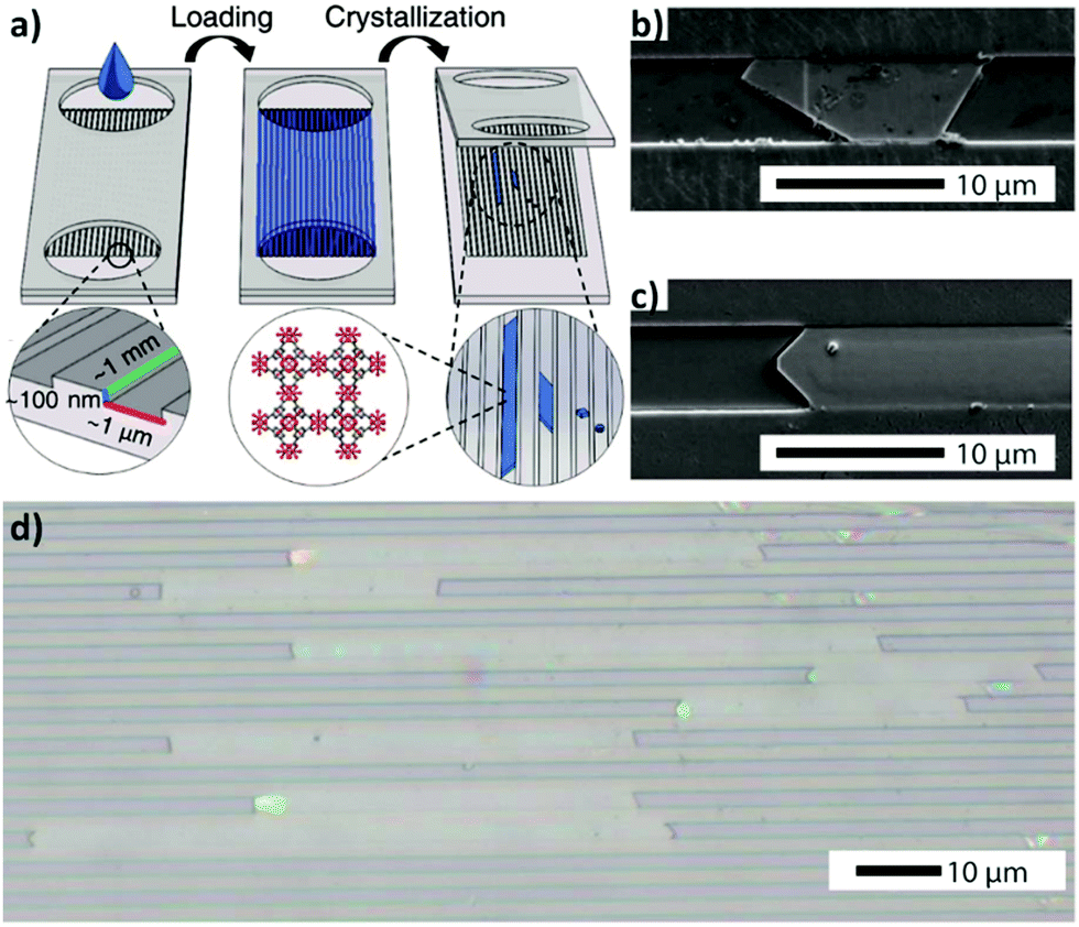 | ||
| Fig. 4 (a) Schematic illustration of the nanofluidic device used for the evaporation driven crystallization approach. (b and c) SEM images demonstrating the confined growth of HKUST-1 crystals in confined nanochambers. (d) An optical image of high aspect ratio HKUST-1 crystals obtained via the method presented in (a). Reproduced with permission from ref. 42 published by The Royal Society of Chemistry. | ||
Recently, confined spaces have also been used to generate conditions that mimic microgravity. These conditions have proved to be an excellent scenario to control both the growth and shape of MOF single crystals. Under these conditions, Puigmartí-Luis et al. have, for example, demonstrated the formation of large single crystals of a peptide-based MOF with unprecedented control over the morphology while growing non-equilibrium shapes such as thin films.43
Instead of constraining MOF crystal growth into small volumes (i.e. micro/nano fluidic channels), confined spaces can also be established with common liquid phase processing techniques such as blade coating. Recently, Park et al. have reported the supersaturation-driven crystallization of MOF thin films in confined spaces via a blade coating approach.44 Here, the supersaturation of a meniscus solution containing HKUST-1 precursors was finely controlled by heating the substrate and moving the blade (Fig. 5a). Changing the substrate temperature and varying the velocity of the blade enabled the fabrication of densely-packed thin films with tuneable thicknesses (down to 450 nm) on different kinds of substrates (Fig. 5b and c).
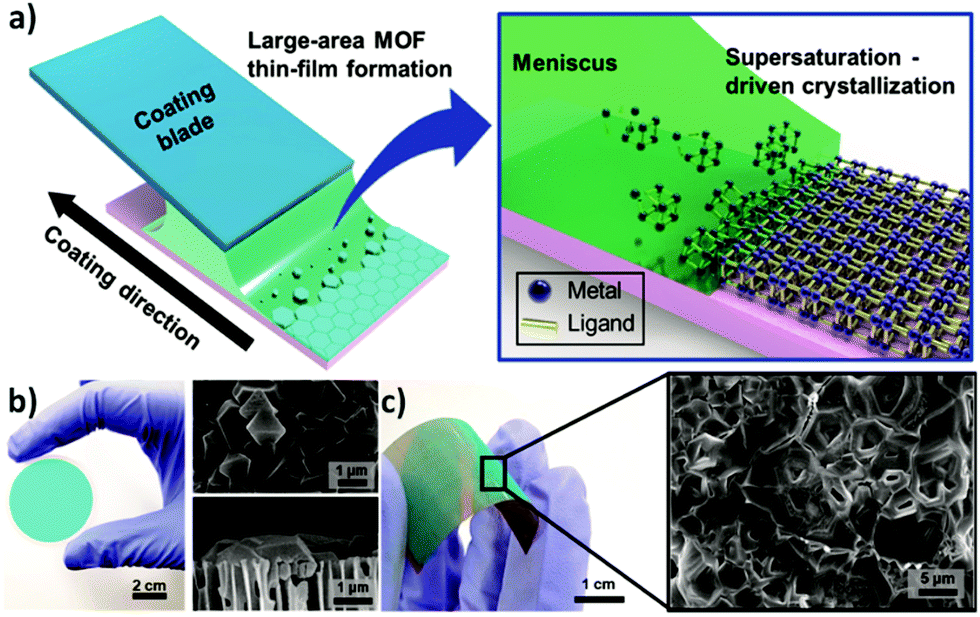 | ||
| Fig. 5 (a) Schematic representation of the meniscus-guided crystallization method and (b and c) optical and corresponding SEM images of HKUST-1 films coated onto different substrates, respectively on an AAO membrane and on a flexible polyimide film. Reproduced from ref. 44 with permission from American Chemical Society, copyright 2019. | ||
Gas phase approaches
While the liquid phase approaches discussed earlier are very attractive, the use of liquid solvents is still a drawback for some applications in digital and information technologies, where thin films are used as dielectrics, barrier layers, and capacitors.45,46 MOF thin films have become an engaging alternative to the existing materials used in the microelectronics industry because in addition to displaying electric conductivity, wide dielectric constants, and high breakdown voltage, they are also recognised for their selective molecular sensing and tuneable dielectric properties.5As in the case of conventional materials found in electronic devices, MOF thin films have currently been grown through a combination of well-established gas phase techniques such as physical vapour deposition (PVD, i.e. sputtering, evaporation, or sublimation) and chemical vapour deposition (CVD).5,45
PVD techniques consist of the condensation of a vaporized form of the film on the substrate by a physical process (e.g. thermally or laser-induced evaporation). However, considering the high temperature usually adopted during the process (300–400 °C) to obtain the crystalline structures, it is not a technique widely used for the fabrication of MOF thin films.
In the case of CVD, a substrate is exposed to a gaseous precursor that chemically reacts with its surface. This type of deposition is appealing due to its scalability and because (in some particular cases) the reaction can take place without the use of a vacuum and at lower temperatures than those required in PVD to reach crystallinity.
An appealing variant of CVD is Atomic Layer Deposition (ALD).47,48 ALD is a surface-limited and self-terminating LbL deposition method, thus allowing the deposition of homogeneous thin films without the use of any solvent.49–54 ALD relies on alternate pulses of reactants and co-reactants in the gas phase, separated by purging steps with an inert gas (e.g. N2, Ar) (Fig. 6). One of the main advantages of ALD, compared to CVD, is that the former can yield conformal films over very complex, high-aspect-ratio and even porous structures, given its surface-limited reaction nature. Also, because ALD is self-terminating, the thickness can be controlled down to the subnanometer. These two characteristics have made ALD a very appealing technique for the microelectronics industry, which has indeed been a key driver in the development of the ALD field.49–54 While ALD refers to processes where only inorganic and metalorganic precursors are used, the term Molecular Layer Deposition (MLD) has been used when one or both precursors are organic, allowing the deposition of hybrid or purely organic films.54,55 In the case of hybrid films, such as MOFs, the organic molecules are bonded to the metal atoms and vice versa, forming periodic thin-film structures, where the nature of the bonds depends on the nature of the organic ligands.53,56,57
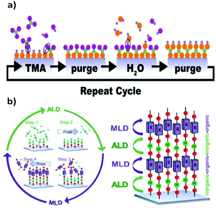 | ||
| Fig. 6 (a) Schematic representation of a typical ALD cycle. Reproduced from ref. 47, copyright (2018), with permission from Elsevier. (b) Schematic representation of the ALD/MLD process where in the ALD part an inorganic precursor is used while in the MLD part an organic precursor is used. Reproduced from ref. 48, copyright (2015), with permission from Elsevier. | ||
The first attempt to deposit a MOF thin film by MLD was reported in 2013 by Salmi et al. using zinc acetate (ZnAc2) and 1,4-benzene dicarboxylic acid (1,4-BDC) as precursors.58 While the as-deposited films were amorphous, polycrystalline forms of MOF-5 could be obtained by placing the samples in a humidity-controlled chamber (60% humidity) for 12 h followed by annealing at 150 °C for 2 h. The conformal and uniform nature of the post-treated MOF-5 film was demonstrated by covering high aspect-ratio structures containing hard-to-access small trenches (Fig. 7).
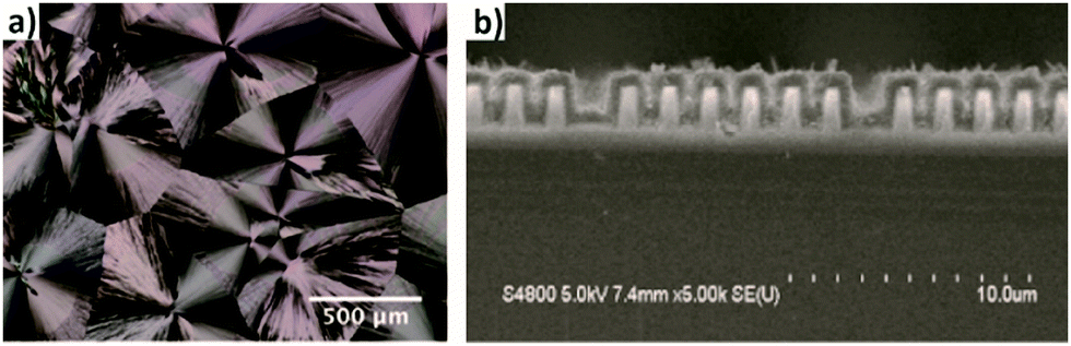 | ||
| Fig. 7 (a) Optical microscope image of a film crystallized in moist air. (b) Cross-sectional FESEM image of a MOF-5 film deposited on a silicon substrate with trenches. Reproduced from ref. 58, copyright (2013), with permission from Elsevier. | ||
Following the same approach, numerous groups have also reported the deposition of polycrystalline films.59–61 In 2016, Nilsen and his team60 described a similar strategy that combined ALD and MLD processes to obtain University of Oslo-66 (UiO-66, zirconium terephthalate) (Fig. 8a–c). By following the reaction of zirconium tetrachloride (ZrCl4) and 1,4-benzenedicarboxylic acid (1,4-BDC, commonly known as terephthalic acid) in situ with a quartz crystal microbalance (QCM) they demonstrated the self-limiting behaviour of the reactions and found ALD-type growth conditions. The as-obtained samples were amorphous and readily reacted with water upon exposure to the environment, causing an increase of the thickness of the film and dramatic changes in its morphology. Moreover, by comparing the X-ray patterns of the samples before and after exposure to moisture, they detected partial crystallization of unreacted 1,4-BDC. The excess linker was removed by introducing water pulses in between the ZrCl4 and 1,4-BDC steps. However, the authors found that the relatively slow desorption of water from the porous film could cause undesirable side reactions with ZrCl4 during subsequent pulses. To overcome this issue, the weakly-bound 1,4-BDC was removed by reacting with acetic acid, which is known to be a modulator of the crystal growth in the synthesis of UiO-66. Finally, crystalline UiO-66 films were obtained by introducing the samples in a sealed autoclave with acetic acid vapour (Fig. 8d).
 | ||
| Fig. 8 Mass gain as a function of time measured in situ in the ALD/MLD process with a quartz crystal microbalance (QCM). The red lines show the standard deviations for the QCM data (= 16), and in blue the N2 purge step. (a) Alternation between ZrCl4 and 1,4-BDC pulses separated by N2 purges (blue). (b) Alternation between ZrCl4, 1,4-BDC and water. (c) ALD/MLD process in which a modulation step with acetic acid is included. (d) Cross-section SEM images of the same surface viewed at 45° and 90° angles. Reproduced from ref. 60 with permission from The Royal Society of Chemistry. | ||
More recently, the same group11 broadened their Zr-based MOF portfolio by developing a procedure involving MLD cycles of 2,6-naphtalenedicarboxylate (2,6-NDC) and biphenyl-4,4′-dicarboxylate (BP-4,4′-DC) with tetraclhorozincate (ZnCl4) as a metallic precursor (Fig. 9a–c and e). The typical cycle used in this work was the following one: 3 s for the ZrCl4 pulse, 2 s of purging, 20 s for the organic linkers, and 2 s of purging. The choice of using rather long pulses for the organic ligands (as compared with standard MLD processes) was due to the steric hindrance effects linked to the bulky nature of the ligands that possibly slowed down the surface kinetics.
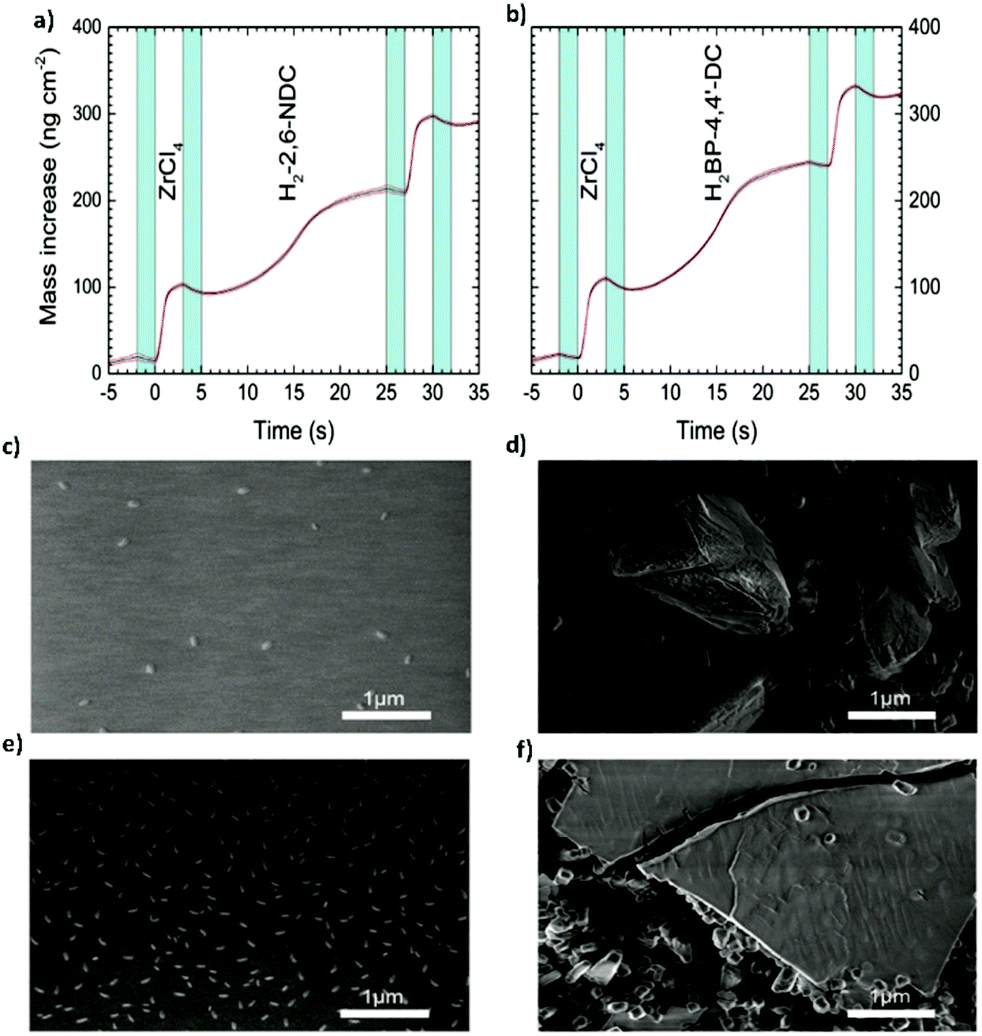 | ||
| Fig. 9 Mass increase during one MLD cycle (a) of the Zr-2,6-NDC process and (b) of the Zr-BP-4,4′-Dc process, measured by the in situ QCM technique. (c) SEM picture of the as-deposited Zr-2,6-NDC film. (d) SEM picture of the Zr-2,6-NDC film after autoclave treatment. (e) SEM picture of the as-deposited Zr-BP-4,4′-DC film. (f) SEM picture of the Zr-BP-4,4′-DC film after autoclave treatment. Reproduced from ref. 11 with permission from The Royal Society of Chemistry. | ||
Ahvenniemi and Karppinen also reported the deposition of Cu-TPA (copper terephthalic acid) MOF thin films using Cu(thd)2 (copper 2,2,6,6-tetramethyl-3,5-heptanedione) and terephthalic acid as precursors under carefully selected conditions.59,62 The precursors were heated before and during the deposition to increase their vapour pressure and facilitate the reaction on top of the substrate. In this case, the possibility to directly obtain a crystalline film was demonstrated by carefully choosing the concentration of the precursor solution and the time necessary for each step of the MLD cycle. To date, it remains the only example of a direct synthesis of polycrystalline MOF films without the necessity of a post-synthesis treatment. Such a difficulty could be a limitation for the application of MLD for the implementation of MOF thin films in microelectronic devices.
Similar to liquid phase approaches, the gas phase ones require spatiotemporal control of the reactants if a film with a precise degree of crystallization is desired. Although it might seem easier to control the reaction and diffusion of the precursors in liquid phase approaches, the area that can be effectively covered with a MOF film is usually very small when compared to those that can be achieved by ALD and MLD. For this reason, metal oxide films deposited by ALD have been recently used to immobilize metal ions and facilitate the MOF crystallization process. Thus, the manufacturing of well-oriented sacrificial layers that can be subsequently converted to MOF thin films through the vapor phase reaction in a closed system is possible with ALD. The first successful example was reported by Ameloot and coworkers in 2016 (Fig. 10a).63,64 The authors used a sacrificial ZnO thin film obtained by ALD to template the synthesis of MOFs. Thus, the ZnO film was subsequently converted to ZIF-8 through a vapor–solid reaction65,66 with 2-methylimidazole in a relatively short time (Fig. 10b–d). To reach the conversion of the metallic thin film into ZIF-8, a temperature higher than the 2-methylimidazole melting point was necessary to increase the amount of organic precursor close to the sacrificial metallic oxide layer. In addition, full transformation of thin (less than 15 nm) sacrificial layers into a MOF film was achieved. However, if thicker films are needed, the slow diffusion of the organic ligands through the MOF film might hamper its full conversion. Also, some problems regarding the homogeneity and continuity of the films over large areas have been noticed.67 For instance, when very thin films (<10 nm) were left to react completely, fast crystal ripening occurred before the ZnO was completely consumed and the continuity of the films was disturbed. As pointed out by Stassin et al., the need for controlling independently the temperature of the substrate and the reaction chamber walls to obtain a desired morphology remains a challenge.67
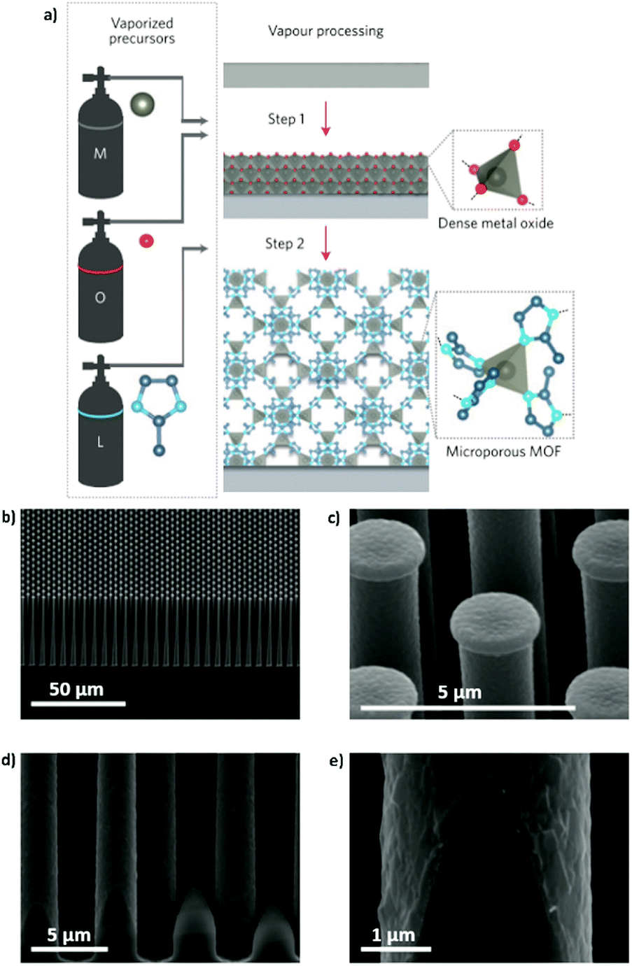 | ||
| Fig. 10 (a) Schematic representation of the CVD route in two steps. Step 1: deposition of the oxide sacrificial layer; step 2: conversion of the metal oxide into a MOF thin film. (b and c) SEM images of a ZIF-8 coating on a silicon pillar array. (d and e) High-magnification SEM pictures of the homogeneous coverage at the base of the pillar, showing that the conformality typical of the ALD process is retained after the coordination replication reaction. Reproduced from ref. 63, copyright (2016), with permission from Elsevier. | ||
Still, the MOF-CVD approach has recently allowed the introduction of MOF thin films as ultra-low k dielectric materials for advanced chip interconnects. As demonstrated by Krishtab et al.,46 ZIF-8 and ZIF-67 (CoOx and 2-methylimidazole) were deposited to fill the narrow gaps between the metallic trenches of a chip. The deposited MOF thin films displayed comparable performance with respect to other cutting-edge dielectrics such as porous organosilica thin films. Moreover, the accompanying volume expansion that results from the transformation of the metal oxide to a MOF enabled uniform growth over the metallic trenches and superior gap-filling. According to the existing literature, the application of MOF thin films prepared by the MOF-CVD approach is currently underway as can be seen in recent work by Pino et al.68 where solid-phase microextraction (SPME) fibres were coated with ZIF-8. Nevertheless, for microelectronic applications, the MOF-CVD approach must be optimized to be compatible with automated cleanroom facilities.64
In all the gas phase approaches reviewed above, the main characteristic has been the absence of solvents during the synthesis procedure. As previously stated, this can be advantageous because it could avoid surface-tension phenomena or eventual corrosion of the final device, and could also lead to a reduction of costs from a scale-up perspective.
Also, in the reported papers, the temperature plays a fundamental role to achieve the deposition of thin films, regardless of their crystallinity. In fact, in all the syntheses that have been reviewed here, the heating of the precursors to improve the reaction kinetics is necessary. This is because of the low volatility of the organic precursors and the competitive reactions that could take place during the process. The need for heating the precursors could be a problem since organic compounds tend to be thermally sensitive. Indeed, the range of temperatures available to tune their vapour pressure is usually quite narrow and dangerously close to the decomposition temperature of the compound itself.
Conclusions and outlook
MOF thin films have aroused growing interest in recent years due to their potential applications in microelectronics, catalysis, and gas separation. Recent developments are undeniably associated with the interesting features of MOF surfaces and their interactions, as well as the possibility of tailoring their properties while minimizing the amount of material used.Although several solution-based techniques have been proposed for the processing of MOF thin films, the ability to carefully control their size and shape while having an efficient and environmentally friendly process remains unaddressed. The most recent liquid phase approaches reported from this perspective (i.e. continuous-flow fluidic approaches and supersaturation-driven crystallization) represent an important step toward the continuous production of MOF thin films with extraordinary control over different reaction parameters. At the same time, gas phase approaches (i.e. MOF-CVD and MLD) are arising as an alternative way, owing to their high control over the thickness and the conformality of polycrystalline films while avoiding the use of solvents. These approaches are summarized in Table 1.
| Team | Year | Method | Material | Thickness | Post-treatment | Key aspect/application | Ref. |
|---|---|---|---|---|---|---|---|
| Salmi L. D. | 2013 | Gas MLD | MOF-5 | — | Crystallization | First MOF film obtained by MLD | 58 |
| Nair S. | 2014–2016 | Liquid IMMP | ZIF-8 | ca. 5 μm | — | Potential control over the ZIF-8 membrane formation for gas separation | 35–37 |
| Kharul U. K. | 2015 | Liquid IMMP | HKUST-1, ZIF-8 | 10–25 μm | — | Easy removal of the solvent with a mild activation process. MOF membranes fabricated for gas separation | 38 |
| Zhang J. | 2015 | Liquid LBL epitaxial growth inside a capillary coated with 3,4-dihydroxy-L-phenylalanine (poly(L-DOPA)) | Cu2(D-cam)2P (D-cam = (1R,3)-(+)-camphorate; L-cam = (1S,3R)-( )-camphorate; P = dabco and bipy) | 350 nm | — | Homochiral MOF for enantiomer separation | 40 |
| Ameloot R. | 2016 | Gas ALD + gas phase reaction | ZIF-8 | ca. 200 nm | — | First MOF-CVD reported. Well controlled thickness. | 63 |
| Karppinen M. | 2016 | Gas ALD/MLD | Cu-TPA | 80–90 nm | — | First and only example of the direct deposition of a crystalline MOF thin film by MLD. Atomic/molecular level control of the film thickness under relatively mild conditions | 62 |
| Nilsen O. | 2016 | Gas ALD/MLD | UiO-66 | From 130 nm as-deposited to 500 nm | Acetic acid vapour exposure | New approach to control the stoichiometry between metal cluster and organic ligands | 60 |
| Jeong H.-K. | 2018 | Liquid combination of microwave assisted seeding and microfluidic secondary growth | ZIF-8 | ca. 800 nm | — | Ultrathin ZIF-8 membranes on polymeric hollow fibres for propylene/propane gas separation | 39 |
| Ameloot R. | 2019 | Gas ALD + gas-phase reaction | ZIF-67 and ZIF-8 | ca. 30 nm | — | Gap filling of narrow spaces between the metallic trenches of a chip | 46 |
| Karppinen M. | 2019 | Gas ALD/MLD | Nd-TP | ca. 94 nm | Crystallization by exposure to humidity at room temperature | Atomic/molecular level control of the film thickness under relatively mild conditions | 59 |
| Puigmartí-Luis J. | 2019 | Liquid in-flow lithography | HKUST-1 | ca. 15 nm | — | First controlled defect engineering of a MOF thin film via advanced mass transport and controlled diffusion in a confined space | 41 |
| Giri G. | 2019 | Liquid nanofluidic approach | HKUST-1 | 100 nm | — | High aspect ratio HKUST-1 crystals for selective small molecule uptake | 42 |
| Park S. | 2019 | Liquid supersaturation driven crystallization | HKUST-1 | Down to 450 nm | — | Meniscus guided precise control of supersaturation | 44 |
| Puigmartí-Luis J. | 2020 | Liquid microfluidic approach in an advection free confined environment | Cu(II) tripeptide glycine-L-histidine-glycine (CuGHG) | — | — | For the first time conditions mimicking microgravity are used to grow and shape MOF single crystals | 43 |
| Nilsen O. | 2020 | Gas ALD/MLD | Zr MOFs with 2,6-NDC and BP-4,4′-DC | — | Acetic acid vapour exposure | Synthesis of thin films with a large range of pore size. Preliminary studies employing MOF thin films in applications such as luminescence and photocatalysis | 11 |
| Ameloot R. | 2020 | Gas ALD + gas phase reaction | MAF-6 | ca. 90 nm | – | Synthesis of a large pore MOF material for the potential adsorption of large molecules | 67 |
| Pino V. | 2020 | Gas ALD + gas phase reaction + solvothermal growth step | ZIF-8 | ca. 3 μm | — | Solid-phase microextraction (SPME) for analytical and pre-concentration schemes | 68 |
Despite the advantages offered by the approaches discussed here, many of their steps demand a more fundamental understanding (e.g. the nucleation process, kinetics, the direction of growth), and sometimes multiple-step approaches are necessary. Thus, concerted efforts from different research and engineering fields are timely and expected. Only a multidisciplinary approach will ultimately allow for the translation of these processes to the industrial landscape. We hope that this Minireview will engage more researchers and engineers in this technological endeavor.
Conflicts of interest
There are no conflicts to declare.Acknowledgements
This work was partially supported by the European Union (European Union's Horizon 2020 FETOPEN-1-2016-2017 research and innovation program under Grant Agreement 801464 and European Research Council Starting Grant: ERC-2015-STG microCrysFact 677020) and the Swiss National Science Foundation (Project No. 200021_181988, 191394). Financial support from the Fondation Nanosciences (Université Grenoble Alpes, France) is also acknowledged through the M-O-Films project. S. P. acknowledges funding from a Consolidator Grant from the European Research Council (ERC) under the European Union's Horizon 2020 research and innovation programme (Grant Agreement No. 771565).Notes and references
- O. M. Yaghi, G. Li and H. Li, Nature, 1995, 378, 703–706 CrossRef CAS.
- J. Liu, F. Yang, Q. Zhang, W. Chen, Y. Gu and Q. Chen, Inorg. Chem., 2019, 58, 3564–3568 CrossRef CAS.
- O. K. Farha, I. Eryazici, N. C. Jeong, B. G. Hauser, C. E. Wilmer, A. A. Sarjeant, R. Q. Snurr, S. T. Nguyen, A. Ö. Yazaydın and J. T. Hupp, J. Am. Chem. Soc., 2012, 134, 15016–15021 CrossRef CAS.
- S. Joseph, D. M. Kempaiah, M. Benzigar, A. V. Baskar, S. N. Talapaneni, S. H. Jhung, D.-H. Park and A. Vinu, J. Mater. Chem. A, 2017, 5, 21542–21549 RSC.
- I. Stassen, N. Burtch, A. Talin, P. Falcaro, M. Allendorf and R. Ameloot, Chem. Soc. Rev., 2017, 46, 3185–3241 RSC.
- M. A. Solomos, F. J. Claire and T. J. Kempa, J. Mater. Chem. A, 2019, 7, 23537–23562 RSC.
- Y. Luo, M. Ahmad, A. Schug and M. Tsotsalas, Adv. Mater., 2019, 31, 1901744 CrossRef.
- L. Jiao, J. Y. R. Seow, W. S. Skinner, Z. U. Wang and H.-L. Jiang, Mater. Today, 2019, 27, 43–68 CrossRef CAS.
- P. Falcaro, K. Okada, T. Hara, K. Ikigaki, Y. Tokudome, A. W. Thornton, A. J. Hill, T. Williams, C. Doonan and M. Takahashi, Nat. Mater., 2017, 16, 342–348 CrossRef CAS.
- Z.-G. Gu, S.-C. Chen, W.-Q. Fu, Q. Zheng and J. Zhang, ACS Appl. Mater. Interfaces, 2017, 9, 7259–7264 CrossRef CAS.
- K. B. Lausund, M. S. Olsen, P.-A. Hansen, H. Valen and O. Nilsen, J. Mater. Chem. A, 2020, 8, 2539–2548 RSC.
- J. Liu, W. Zhou, J. Liu, Y. Fujimori, T. Higashino, H. Imahori, X. Jiang, J. Zhao, T. Sakurai, Y. Hattori, W. Matsuda, S. Seki, S. K. Garlapati, S. Dasgupta, E. Redel, L. Sun and C. Wöll, J. Mater. Chem. A, 2016, 4, 12739–12747 RSC.
- A. H. Assen, O. Yassine, O. Shekhah, M. Eddaoudi and K. N. Salama, ACS Sens., 2017, 2, 1294–1301 CrossRef CAS.
- S. Hurrle, S. Friebe, J. Wohlgemuth, C. Wöll, J. Caro and L. Heinke, Chem. – Eur. J., 2017, 23, 2294–2298 CrossRef CAS.
- J.-L. Zhuang, A. Terfort and C. Wöll, Coord. Chem. Rev., 2016, 307, 391–424 CrossRef CAS.
- W.-J. Li, M. Tu, R. Cao and R. A. Fischer, J. Mater. Chem. A, 2016, 4, 12356–12369 RSC.
- J. Liu and C. Wöll, Chem. Soc. Rev., 2017, 46, 5730–5770 RSC.
- W. Li, Prog. Mater. Sci., 2019, 100, 21–63 CrossRef.
- J. Benito, S. Sorribas, I. Lucas, J. Coronas and I. Gascon, ACS Appl. Mater. Interfaces, 2016, 8, 16486–16492 CrossRef CAS.
- K. Ikigaki, K. Okada, Y. Tokudome, T. Toyao, P. Falcaro, C. J. Doonan and M. Takahashi, Angew. Chem., Int. Ed., 2019, 58, 6886–6890 CrossRef CAS.
- M. J. Van Vleet, T. Weng, X. Li and J. R. Schmidt, Chem. Rev., 2018, 118, 3681–3721 CrossRef CAS.
- S. D. Worrall, H. Mann, A. Rogers, M. A. Bissett, M. P. Attfield and R. A. W. Dryfe, Electrochim. Acta, 2016, 197, 228–240 CrossRef CAS.
- C. Warakulwit, S. Yadnum, C. Boonyuen, C. Wattanakit, A. Karajic, P. Garrigue, N. Mano, D. Bradshaw, J. Limtrakul and A. Kuhn, CrystEngComm, 2016, 18, 5095–5100 RSC.
- N. Campagnol, T. R. C. Van Assche, M. Li, L. Stappers and J. Fransaer, J. Mater. Chem. A, 2016, 4, 3914–3925 RSC.
- Z. G. Gu and J. Zhang, Coord. Chem. Rev., 2019, 378, 513–532 CrossRef CAS.
- X. Bai, D. Chen, L. Li, L. Shao, W. He, H. Chen, Y. Li, X. Zhang, L. Zhang, T. Wang, Y. Fu and W. Qi, ACS Appl. Mater. Interfaces, 2018, 10, 25960–25966 CrossRef CAS.
- J. U. Balderas, D. Navarro, V. Vargas, M. M. Tellez-Cruz, S. Carmona and C. Falcony, J. Lumin., 2019, 212, 322–327 CrossRef CAS.
- B. Reif, J. Somboonvong, F. Fabisch, M. Kaspereit, M. Hartmann and W. Schwieger, Microporous Mesoporous Mater., 2019, 276, 29–40 CrossRef CAS.
- V. Chernikova, O. Shekhah and M. Eddaoudi, ACS Appl. Mater. Interfaces, 2016, 8, 20459–20464 CrossRef CAS.
- X. Liu, M. Kozlowska, T. Okkali, D. Wagner, T. Higashino, G. Brenner-Weiß, S. M. Marschner, Z. Fu, Q. Zhang, H. Imahori, S. Bräse, W. Wenzel, C. Wöll and L. Heinke, Angew. Chem., Int. Ed., 2019, 58, 9590–9595 CrossRef CAS.
- G. M. Whitesides, Science, 2002, 295, 2418–2421 CrossRef CAS.
- J. Puigmartí-Luis, Chem. Soc. Rev., 2014, 43, 2253–2271 RSC.
- C. Echaide-Górriz, C. Clément, F. Cacho-Bailo, C. Téllez and J. Coronas, J. Mater. Chem. A, 2018, 6, 5485–5506 RSC.
- S. Sevim, A. Sorrenti, C. Franco, S. Furukawa, S. Pané, A. J. Demello and J. Puigmartí-Luis, Chem. Soc. Rev., 2018, 47, 3788–3803 RSC.
- A. J. Brown, N. A. Brunelli, K. Eum, F. Rashidi, J. R. Johnson, W. J. Koros, C. W. Jones and S. Nair, Science, 2014, 345, 72–75 CrossRef CAS.
- K. Eum, A. Rownaghi, D. Choi, R. R. Bhave, C. W. Jones and S. Nair, Adv. Funct. Mater., 2016, 26, 5011–5018 CrossRef CAS.
- K. Eum, C. Ma, A. Rownaghi, C. W. Jones and S. Nair, ACS Appl. Mater. Interfaces, 2016, 8, 25337–25342 CrossRef CAS.
- B. P. Biswal, A. Bhaskar, R. Banerjee and U. K. Kharul, Nanoscale, 2015, 7, 7291–7298 RSC.
- M. J. Lee, M. R. Abdul Hamid, J. Lee, J. S. Kim, Y. M. Lee and H.-K. Jeong, J. Membr. Sci., 2018, 559, 28–34 CrossRef CAS.
- Z.-G. Gu, W.-Q. Fu, X. Wu and J. Zhang, Chem. Commun., 2016, 52, 772–775 RSC.
- S. Sevim, C. Franco, H. Liu, H. Roussel, L. Rapenne, J. Rubio-Zuazo, X. Chen, S. Pané, D. Muñoz-Rojas, A. J. DeMello and J. Puigmartí-Luis, Adv. Mater. Technol., 2019, 4, 1800666 CrossRef.
- S. Guthrie, L. Huelsenbeck, A. Salahi, W. Varhue, N. Smith, X. Yu, L. U. Yoon, J. J. Choi, N. Swami and G. Giri, Nanoscale Adv., 2019, 1, 2946–2952 RSC.
- A. Sorrenti, L. Jones, S. Sevim, X. Cao, A. J. DeMello, C. Martí-Gastaldo and J. Puigmartí-Luis, J. Am. Chem. Soc., 2020, 142, 9372–9381 CrossRef CAS.
- J.-C. Lee, J.-O. Kim, H.-J. Lee, B. Shin and S. Park, Chem. Mater., 2019, 31, 7377–7385 CrossRef CAS.
- I. Stassen, D. De Vos and R. Ameloot, Chem. – Eur. J., 2016, 22, 14452–14460 CrossRef CAS.
- M. Krishtab, I. Stassen, T. Stassin, A. J. Cruz, O. O. Okudur, S. Armini, C. Wilson, S. De Gendt and R. Ameloot, Nat. Commun., 2019, 10, 3729 CrossRef.
- F. Grillo, J. A. Moulijn, M. T. Kreutzer and J. R. van Ommen, Catal. Today, 2018, 316, 51–61 CrossRef CAS.
- T. Tynell and M. Karppinen, in Oxide Thin Films, Multilayers, and Nanocomposites, ed. P. Mele, T. Endo, S. Arisawa, C. Li and T. Tsuchiya, Springer International Publishing, Cham, 2015, pp. 159–179 Search PubMed.
- T. Muneshwar, M. Miao, E. R. Borujeny and K. Cadien, Handbook of Thin Film Deposition, Elsevier, 2018, pp. 359–377 Search PubMed.
- T. Tynell, T. Aizawa, I. Ohkubo, K. Nakamura and T. Mori, J. Cryst. Growth, 2016, 449, 10–14 CrossRef CAS.
- E. Ahvenniemi, A. R. Akbashev, S. Ali, M. Bechelany, M. Berdova, S. Boyadjiev, D. C. Cameron, R. Chen, M. Chubarov, V. Cremers, A. Devi, V. Drozd, L. Elnikova, G. Gottardi, K. Grigoras, D. M. Hausmann, C. S. Hwang, S.-H. Jen, T. Kallio, J. Kanervo, I. Khmelnitskiy, D. H. Kim, L. Klibanov, Y. Koshtyal, A. O. I. Krause, J. Kuhs, I. Kärkkänen, M.-L. Kääriäinen, T. Kääriäinen, L. Lamagna, A. A. Łapicki, M. Leskelä, H. Lipsanen, J. Lyytinen, A. Malkov, A. Malygin, A. Mennad, C. Militzer, J. Molarius, M. Norek, Ç. Özgit-Akgün, M. Panov, H. Pedersen, F. Piallat, G. Popov, R. L. Puurunen, G. Rampelberg, R. H. A. Ras, E. Rauwel, F. Roozeboom, T. Sajavaara, H. Salami, H. Savin, N. Schneider, T. E. Seidel, J. Sundqvist, D. B. Suyatin, T. Törndahl, J. R. van Ommen, C. Wiemer, O. M. E. Ylivaara and O. Yurkevich, J. Vac. Sci. Technol., A, 2017, 35, 010801 CrossRef.
- D. Muñoz-Rojas and J. MacManus-Driscoll, Mater. Horiz., 2014, 1, 314–320 RSC.
- J. Penttinen, M. Nisula and M. Karppinen, Chem. – Eur. J., 2017, 23, 18225–18231 CrossRef CAS.
- M. Nisula and M. Karppinen, Nano Lett., 2016, 16, 1276–1281 CrossRef CAS.
- A. Tanskanen and M. Karppinen, Sci. Rep., 2018, 8, 8976 CrossRef CAS.
- P. Sundberg and M. Karppinen, Beilstein J. Nanotechnol., 2014, 5, 1104–1136 CrossRef.
- X. Meng, J. Mater. Chem. A, 2017, 5, 18326–18378 RSC.
- L. D. Salmi, M. J. Heikkilä, E. Puukilainen, T. Sajavaara, D. Grosso and M. Ritala, Microporous Mesoporous Mater., 2013, 182, 147–154 CrossRef CAS.
- E. Ahvenniemi and M. Karppinen, Chem. Mater., 2016, 28, 6260–6265 CrossRef CAS.
- K. B. Lausund and O. Nilsen, Nat. Commun., 2016, 7, 13578 CrossRef CAS.
- A. Ghazy, M. Safdar, M. Lastusaari and M. Karppinen, Chem. Commun., 2020, 56, 241–244 RSC.
- E. Ahvenniemi and M. Karppinen, Chem. Commun., 2016, 52, 1139–1142 RSC.
- I. Stassen, M. Styles, G. Grenci, H. Van Gorp, W. Vanderlinden, S. De Feyter, P. Falcaro, D. De Vos, P. Vereecken and R. Ameloot, Nat. Mater., 2016, 15, 304–310 CrossRef CAS.
- A. J. Cruz, I. Stassen, M. Krishtab, K. Marcoen, T. Stassin, S. Rodríguez-Hermida, J. Teyssandier, S. Pletincx, R. Verbeke, V. Rubio-Giménez, S. Tatay, C. Martí-Gastaldo, J. Meersschaut, P. M. Vereecken, S. De Feyter, T. Hauffman and R. Ameloot, Chem. Mater., 2019, 31, 9462–9471 CrossRef CAS.
- Y. Zhao, N. Kornienko, Z. Liu, C. Zhu, S. Asahina, T.-R. Kuo, W. Bao, C. Xie, A. Hexemer, O. Terasaki, P. Yang and O. M. Yaghi, J. Am. Chem. Soc., 2015, 137, 2199–2202 CrossRef CAS.
- P. C. Lemaire, J. Zhao, P. S. Williams, H. J. Walls, S. D. Shepherd, M. D. Losego, G. W. Peterson and G. N. Parsons, ACS Appl. Mater. Interfaces, 2016, 8, 9514–9522 CrossRef CAS.
- T. Stassin, I. Stassen, J. Marreiros, A. J. Cruz, R. Verbeke, M. Tu, H. Reinsch, M. Dickmann, W. Egger, I. F. J. Vankelecom, D. E. De Vos and R. Ameloot, Chem. Mater., 2020, 32, 1784–1793 CrossRef CAS.
- P. Rocío-Bautista, A. Gutiérrez-Serpa, A. J. Cruz, R. Ameloot, J. H. Ayala, A. M. Afonso, J. Pasán, S. Rodríguez-Hermida and V. Pino, Talanta, 2020, 215, 120910 CrossRef.
Footnote |
| † These author contributed equally to the work. |
| This journal is © The Royal Society of Chemistry 2021 |