Exploiting hydrophobicity and hydrophilicity in nanopores as a design principle for “smart” MOF microtanks for methane storage†
Ryther
Anderson
,
Bomsaerah
Seong
,
Zöe
Peterson
,
Molly
Stevanak
,
Moises A.
Carreon
 and
Diego A.
Gómez-Gualdrón
 *
*
Department of Chemical and Biological Engineering, Colorado School of Mines, Golden, CO 80401, USA. E-mail: dgomezgualdron@mines.edu
First published on 22nd July 2019
Abstract
Widespread use of methane-powered vehicles likely requires the development of efficient on-board methane storage systems. A novel concept for methane storage is the nanoporous microtank, which is based on a millimeter-sized nanoporous pellet (the core) surrounded by an ultrathin membrane (the shell). Mixture adsorption simulations in idealized pores indicate that by combining a pellet that features large, hydrophobic pores with a membrane featuring small, hydrophilic pores, it would be possible to trap a large amount of “pressurized” methane in the pellet while keeping the external pressure low. The methane would be trapped by sealing the surrounding membrane with the adsorption of a hydrophilic compound such as methanol. Additional simulations in over 2000 hypothesized metal–organic frameworks (MOFs) indicate that the above design concept could be exploited using real nanoporous materials. Structure–property relationships derived from these simulations indicate that MOFs suitable for the core (storing over 250 cc(STP)CH4 per cc) should have a pore size in the 12–14 Å range and linkers without appreciably hydrophilic moieties. On the other hand, MOFs suitable for the shell should have a pore size less than 9 Å and linkers with hydrophilic functional groups such as –CN, –NO2, –OH and –NH2. Simulation snapshots suggest that the hydrogen bonding between these groups and hydrophilic moieties of methanol would be critical for the sealing function.
Design, System, ApplicationDue to their exceptional chemical and structural tunability, metal–organic frameworks (MOFs) have long been considered promising materials for methane on-board storage in vehicular applications. However, recent high-throughput computational studies have suggested the existence of fundamental limits for the amount of methane stored that can be stored in MOFs at a given pressure. In this work, we use grand canonical Monte Carlo (GCMC) simulations to develop molecular design principles for a hierarchical material design concept: the nanoporous “microtank”. The microtank concept could help overcome the performance limits found in single crystal materials. Microtanks can be synthesized by coating a nanoporous pellet with a reversibly sealable nanoporous membrane that, when sealed, can keep methane in the core material even at low external pressures. Because this concept has recently been introduced experimentally, there are no rational strategies in place to optimize microtank performance. Here we begin to develop these strategies from a thermodynamic perspective. The molecular design principles emerging from this work were first derived in idealized pores and then shown to be transferable to more realistic materials by simulations in ca. 2000 MOFs. These principles could guide the experimental development of microtanks, not only for storage of natural gas but also for other gases and molecules. |
1. Introduction
The U.S. has abundant reserves of natural gas (which is mostly methane),1 making methane-powered vehicles an enticing prospect, especially considering that methane combustion emits fewer pollutants and 25% less CO2 than gasoline.2 The incumbent method to store methane in on-board tanks is by densification to 265 cc(STP) per cc via compression to 250 bar. This permits having enough gas power a vehicle through a commercially appealing driving range.3,4 Although, as the stored gas is delivered to the engine, the tank pressure eventually goes down to 5.8 bar, the high initial storage pressure creates safety concerns that require the use of cumbersome tanks built from expensive materials.5 Therefore, to enable widespread use of methane-powered vehicles, methods for reducing the storage pressure, and thus vehicle cost, are critically needed.6One of the most promising methods to reduce the storage pressure is to load the storage tank with a porous material that can densify the gas fuel at more moderate tank pressures by adsorbing methane within the material pores.3,7,8 Since adsorption is driven by interaction of the gas with the internal surface of the material, porous crystals with a high-surface area such as metal–organic frameworks (MOFs)9 have long been considered attractive for natural gas storage.8,10 However, a series of high-throughput computational screening studies11–13 in thousands of porous crystals suggested that there may be fundamental limits (due to material design constraints) preventing the desired methane adsorption levels to be reached in “stand-alone” porous crystals at moderate tank pressures. For instance, Gómez-Gualdrón et al.11 suggested a limit of around 200 cc(STP) per cc for deliverable capacity when operating at room temperature and with a pressure swing between 65 and 5.8 bar (the deliverable capacity is the difference in gas loading between the highest and the lowest pressure).
Experimental efforts have been consistent with these results in that no material has been reported with a deliverable capacity higher than 190 cc(STP) per cc (the deliverable capacity for MOF UTSA-110) for the 65 bar ↔ 5.8 bar swing.3,14,15 Therefore, some recent experiments have explored alternative operating conditions.16 For instance, Chen and coworkers17 reported a 197 cc(STP) per cc deliverable capacity for MAF-38, but with an 80 bar ↔ 5 bar swing. Eddaoudi and coworkers18 reported 264 cc(STP) per cc for Al-soc-MOF-1, but with an 80 bar ↔ 5 bar swing at 258 K, while Zhang and coworkers19 reported 289 cc(STP) per cc for ST-2, but with a 200 bar ↔ 5 bar swing.
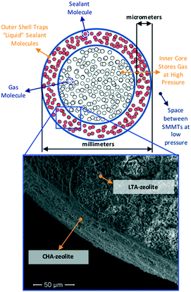
The above considerations underline the critical need for radically new material design strategies. To this end, a novel material design concept combining two porous materials could allow for desired levels of adsorption while keeping the original goal of maintaining low tank pressure. Here, we focus on a hierarchical material design concept introduced experimentally by Carreon and coworkers, which we call smart nanoporous microtanks.20,21 In these microtanks, a millimeter-sized pellet (the core) made of a nanoporous material is covered by a micrometer-thick membrane made of a different nanoporous material as shown in Fig. 1. The microtank core can be filled with methane at high pressure, which can subsequently be trapped by blocking the pores of the membrane material with “sealant” molecules. Thus, the filled membrane keeps the “high-pressure” methane within the microtank, allowing for the pressure outside the microtank to be kept relatively low. The process to fill the microtank is schematized in Fig. 2. The pressurized methane can be released as needed by increasing the temperature of the system, causing the sealant to slowly desorb, allowing the diffusion of methane from the core, through the membrane, and out of the microtank.
 | ||
| Fig. 2 Schematic illustrating the sequence of steps to load and “seal” smart porous microporous tanks (represented as in Fig. 1). The relative thickness of the pellet and shell is not at scale. | ||
Initial forays exploring this concept used zeolite 5A as the core and mesoporous MCM-48 as the membrane.20 The microtanks were first loaded with methane at 50 bar and then the microtank was “sealed” with 2,2-dimethylbutane (DMB), which allowed the external pressure to fall to 1 bar. DMB did not displace methane from the core because DMB is too large a molecule to enter the small pores of zeolite 5A. The caveat is that the small pores of zeolite 5A limited the methane loading to only 50 cc(STP) per cc. Evidently, a core with bigger pores that can load more methane is desired. However, bigger pores could also allow the diffusion of DMB to the core, likely resulting in the displacement of a significant portion of the stored methane (effectively reducing storage capacity). On the other hand, while DMB was relatively effective for sealing methane in the core, it still allowed the escape of methane during a 6 h period before the microtank loading leveled out at 40 cc(STP) per cc.20 Inspired by these experimental results, we asked the question: are there some material design and selection principles that would enable the fabrication of more effective smart nanoporous microtanks?
An effective microtank is one that stores large quantities of methane without allowing for significant methane leakage. Given the significant synthetic effort that realizing each new microtank design entails, we went about answering our question using molecular simulations. While both thermodynamics and kinetics play a role in the functioning of these microtanks, here we focus on how the molecular design of core and shell materials impact relevant thermodynamic properties. In the first part of this work, we study model graphene and graphene oxide slit pores to establish preliminary design principles without the complexities that arise when combining different pore geometries and chemistries in realistic nanoporous materials. In the second part of this work, we explore a 2000-MOF database under several operating conditions to investigate how these design principles can be exploited in more realistic structures.
2. Computational methods
The idealized pore models (Fig. 3) were built and geometry-optimized in Materials Studio 6.0. Graphene models were built as perfectly flat honeycomb-patterned layers of sp2 carbon in a periodic unit cell with varying distance (H) between layers (α = β = 90°, γ = 120°, a = b = 10 Å, c = H). Graphene oxide models were built by introducing hydroxyl groups on the graphene models in a diamond pattern. After optimization, the carbon layer was no longer perfectly flat due to the sp3 character of the oxidized carbon. Lennard-Jones (LJ) potentials were used to describe gas–gas and gas–framework interactions. Coulomb's law was used to describe any charge–charge interactions. LJ parameters and partial charges for methane, methanol and DMB were assigned according to their respective TraPPE models.22,23 LJ parameters for graphene and graphene oxide were assigned according to the UFF force field.24 No partial charges were used on the graphene model. Partial charges for the C–OH moieties present in the graphene oxide model were assigned to mimic the charges for the TraPPE force field for C–OH moieties in 2-methylpropan-2-ol.22 More force field details can be found in Fig. S1.†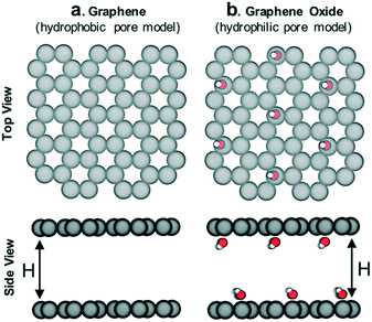 | ||
| Fig. 3 Schematic of (a) hydrophobic and (b) hydrophilic pore models in which adsorption of methane/sealant mixtures was simulated. The interlayer distance H was varied (8 Å, 12 Å, 16 Å and 28 Å) so as to also study the influence of pore size (more details in Fig. S4†). C: gray, O: red, H: white. | ||
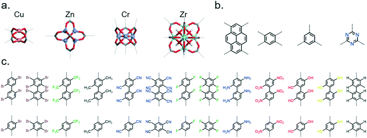
Prototypes for the ∼2000 studied MOFs were constructed using the topologically based crystal constructor (ToBaCCo) code.25,26 The prototypes were then optimized using LAMMPS27 while describing the energetics of the structures with the Dreiding force field.28 Not all potentially useful moieties were included in the created MOFs, but a diversity of functionalities were included to allow us to study the effect of hydrophobicity/hydrophilicity while keeping screening tractable. In the created MOF for GCMC simulations, LJ parameters for MOF atoms were assigned according to the Dreiding force field.28 Partial charges for MOF atoms were assigned using the molecular-building-block-based (MBBB) approach,29 which maps DFT charges calculated on single building blocks onto MOFs constructed from those building blocks. The largest pore diameter (LPD) of each MOF was extracted from the pore size distribution, which was computationally obtained by using the random sphere insertion method of Gelb and Gubbins.30
Adsorption loadings were predicted by running grand canonical Monte Carlo (GCMC) simulations in RASPA-2.0.31 The gas mixture pressure and composition were such that the partial pressure of methane varied between 0 and 100 bar, while the partial pressure of the sealant remained constant and equal to the vapor pressure of the liquid sealant (i.e. having the same chemical potential as liquid methanol or DMB). The Peng–Robinson equation of state was used to calculate fugacities and the corresponding chemical potentials. GCMC simulations used 2000 and 5000 cycles for equilibration and data collection, respectively. Each cycle is composed of N Monte Carlo moves (translation, rotation, insertion/deletion, identity change), where N is the highest number between 20 and the number of adsorbates in the simulation cell. A 12.8 Å cutoff was used for dispersion interactions, while Ewald summation was used to calculate long-range electrostatic interaction energy. Lorentz–Berthelot mixing rules were used to derive LJ parameters for interactions between different atom types.
3. Results and discussion
3.1 Establishing design principles using idealized pores
We hypothesize that by using a small hydrophilic sealant like methanol one could design (i) a hydrophobic core material that could “reject” the sealant without the need of a size-exclusion mechanism, enabling the use of bigger pores, therefore allowing for higher methane loadings, and (ii) a hydrophilic membrane that could “reject” methane when the sealant is present, hence preventing the escape of methane. To test our design hypothesis, we performed GCMC simulations to model the adsorption of methane/sealant mixtures in slit-pore models (Fig. 3) based on graphene (hydrophobic) or graphene oxide (hydrophilic) layers of various separations (H = 8 Å, 12 Å, 16 Å and 28 Å), whose properties and appearance are shown in Table S1 and Fig. S2,† respectively.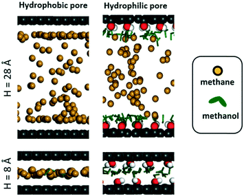 | ||
| Fig. 5 Simulation snapshots for adsorption of methane and methanol mixtures when methane pressure is 100 bar. Pore colors follow the same convention as in Fig. 3. | ||
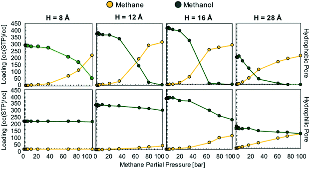
In the hydrophobic pore (i.e. graphene) at H = 8, 12, 16 and 28 Å, methane starts to “take over” the pore space at 85, 60, 50, and 30 bar, respectively (Fig. 4). This indicates that, if the sealant is hydrophilic, by designing the core of the porous microtank to be hydrophobic, it is possible to make a core with large pore sizes that in turn enable the storage of high quantities of methane at relevant pressures. In such cases, even if the pores are accessible to the sealant, energetic constraints will keep the sealant out of the core. The methane loadings at 100 bar were 311 and 291 cc(STP) per cc for H = 12 and 16 Å, respectively, with no methanol co-adsorbed at all. Indeed, these methane loadings are the same loadings observed from the pure methane isotherms at 100 bar for these pores (Fig. S3†).
In the hydrophilic pore (i.e. graphene oxide) it is harder for methane to preferentially adsorb over methanol than in the hydrophobic pore. This occurs due to the formation of a methanol “monolayer” associating via electrostatic interactions with the hydrophilic hydroxyl groups on the pore wall (Fig. 5, right column). Consequently, no methane pressure (at least up to 100 bar) resulted in a higher loading of methane than methanol. For H = 8 and 12 Å the methane loading is negligible or nearly so because the methanol monolayer occupies essentially the entire pore. As with the hydrophobic pore, the methane loadings in the hydrophilic pore became larger as pore size increased. For instance, for H = 28 Å, the loadings of methane and methanol are about equal (on a molar basis) when the methane pressure is 100 bar. Fig. 5 shows that this occurs because once the methanol monolayer is formed, the methyl groups of all sealant molecules point toward the pore, creating a hydrophobic environment that is then filled with methane. Simulation snapshots for all other cases involving methanol are shown in Fig. S4.†
In the above scenario, once the membrane is filled with methanol, the external methane pressure could be dropped without methane escaping from the core. Why? Because while the methane loading in the core no longer corresponds to the loading resulting from equilibrium with the external bulk phase, the methanol loading in the membrane does. Therefore, there would be no “thermodynamic force” for the methanol in the membrane to escape, and for methane in the core to escape it would first have to diffuse through the methanol in the membrane (see Fig. S5† for more details). However, for a well-designed shell material, there would be no thermodynamic force for methane to diffuse from the core to the shell. Based on the above, methane would be expected to be retained in the core, even before diffusion barriers associated with overcoming capillary forces of the adsorbed sealant (as discussed earlier by Carreon and coworkers)20 are even considered. Notice, however, that the effectiveness of the sealing effect depends on a combination of the polarity of the chemical moieties in the pore and pore size as shown in Fig. S6.†
We emphasize that the anticipated “sealing” scenario described above is based on calculated thermodynamic properties, while a full understanding of the involved dynamics and explicit observation of the sealing effect requires the use of large-scale molecular dynamics (MD) simulations (and experiments). Relatedly, to release the methane from the core, the metastable equilibrium described above must be disturbed, which could be accomplished by, for instance, a suitable increase in temperature. Due to the complex dynamics that will arise upon destabilization, eventual control of the rate of discharge will require a deeper understanding of the kinetics of (non-equilibrium) diffusion also using MD simulations, which is beyond the scope of this work. Nonetheless, an intriguing prospect is that given the “s-shaped” methane isotherm (Fig. 4, top row), methane/sealant exchange between the core and the shell may actually help pull methane out to boost the deliverable capacity. It is noteworthy that the appeal of s-shaped isotherms is what has driven recent attention to methane adsorption in flexible MOFs.32–34
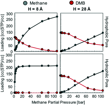
This is in stark contrast with the hydrophilic sealant, which was completely displaced by methane at 100 bar in three of the hydrophobic pore models (H = 12, 16, and 28 Å). Thus, when using a hydrophobic sealant, the attainable methane loadings in the microtank core are not as high as with the hydrophilic sealant. This occurs because small pores (H = 8 Å), which limit the possible amount of stored methane, are needed to keep the large hydrophobic sealant molecules out (via a size-exclusion mechanism). These small pores result in methane loadings at 100 bar of 271 and 208 cc(STP) per cc for the graphene and graphene oxide models, respectively. Once the pores become bigger, the methane loadings at 100 bar fall below 170 cc(STP) per cc due to DMB co-adsorption (Fig. 6).
Also, in stark contrast to the hydrophilic sealant (methanol) is that DMB has more difficulty in completely keeping methane out of the pores (regardless of pore chemistry) if the methane pressure is sufficiently high. This is certainly counterproductive to the proper functioning of the sealing membrane, as the sealant molecule needs to effectively block methane from escaping the core material. The difficulty for DMB to keep methane out primarily stems from the absence of an interaction specific to DMB such as the hydrogen bonding formed by methanol with hydroxyl groups. This is apparent in the corresponding simulation snapshots (Fig. S8†). On the basis of the mixture isotherms, the hydrophobic sealant DMB would retain methane in the core most effectively at core pressures of 40 bar or lower, although kinetic effects may help retain the methane at higher core pressures (e.g. experiments by Carreon and coworkers in ref. 20 were made at 50 bar). However, the potential advantage of a hydrophilic sealant when aiming for higher core pressures and more stored methane is clear.
3.2 Establishing design principles using MOFs
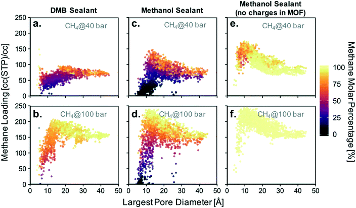
Based on the isotherms for the idealized pores (Fig. 4), we decided to focus on calculating the loadings of methanol and DMB in our database for methane partial pressures of 40, 60, 80, and 100 bar. All results are presented together in Fig. S9,† with the results for the lowest and highest pressure presented in Fig. 8a–d. While the position of a particular point in Fig. 8 indicates the GCMC-calculated methane loading and largest pore diameter (LPD) of the corresponding MOF, the color of the point indicates what percentage of all adsorbed molecules within the MOF is methane. Candidate MOFs for the core should have high methane loading at the storage pressure, while candidate MOFs for the shell should have negligible methane loading.
The trends observed from our simulations on MOFs are consistent with our observations for the idealized pores. MOFs with large pores (high void fraction) tend to have higher absolute methane loading and a higher molar percentage of methane than MOFs with small pores (low void fraction). If the goal for the core material were to maximize this percentage, one would choose a MOF with a pore as large as possible. However, since the goal for the core is actually to maximize methane loading, one needs to consider the pore size (or void fraction) that maximizes the latter. When using methanol as a sealant, the optimal pore size (void fraction) for methane loadings is 12–14 Å (0.82). When using DMB, the optimal pore size (void fraction) somewhat increases to 16–20 Å (0.85). However, consistent with our simulations in idealized pores, it is clear that methanol allows for higher methane loadings in the core materials than DMB (Table 1). Again, this occurs because DMB compete with methane for occupancy in large, non-polar pores.
| Methane partial pressure | Sealant | |
|---|---|---|
| DMB | Methanol | |
| 40 bar | 149 | 174 |
| 60 bar | 165 | 213 |
| 80 bar | 177 | 238 |
| 100 bar | 207 | 254 |
Also consistent with our observations from the idealized pore simulations, some MOFs with small pores are potential candidates for the shell material as they are occupied with nearly 100% methanol even when the vast majority of the gas phase is composed of methane. Again, this occurs more often when the sealant is methanol instead of DMB, which underscores the potential advantage of using the hydrophilic sealant. This can be appreciated in Fig. 8 by the higher abundance of points where essentially no methane is present for the methanol case.
MOFs whose pores are dominated by methanol can be encountered for pore sizes (void fractions) smaller than 9 Å (<0.55). An ideal candidate material for the shell needs the percentage of methane adsorbed to be negligible. The absolute loading of sealant is irrelevant, although materials that successfully exclude methane tend to have high absolute methanol loadings as well. Notice that among the 2000 screened MOFs, candidate materials for the shell are much scarcer than candidate materials for the core. This suggests that the realization of a suitable shell will be one of the most challenging aspects of microtank development.
Before continuing our discussion, notice that there are notable outliers in Fig. 8a and b having low methane concentration in the pores despite LPDs larger than 15 Å (a pore size that is expected to result in relatively high methane adsorption). These outliers are the result of methanol outcompeting methane for certain regions of the pore volume for a particular set of MOFs, a phenomenon which results from pore polydispersity in some structures. Specifically, all of the outlying points are MOFs of either the csq or ceq topologies, which combine large pores with much smaller pores (up to five times smaller for some csq MOFs). The latter provide small electrostatic binding pockets that preferentially bind methanol due to the interaction with highly charged atoms of metal nodes, hence reducing the expected methane loading.
As noted above, the chemistry of the pore is bound to play a crucial role in the competitive adsorption of methane and methanol. The chemistry of the pore affects adsorption in MOFs through “non-dispersive” interactions (e.g. electrostatic interactions) as earlier noted by the effect of functional group polarity in the idealized pores (Fig. S5†). Therefore, as a method to separate the effect of chemistry from the effect of structure, we performed simulations where MOF atom charges were “turned off.” This artificially removes electrostatic interactions between methanol and the MOF. As a result, no MOF structure—regardless of pore size—was able to preferentially adsorb methanol (Fig. 8e and f).
For a methane pressure of 40 bar several materials present methanol molar concentrations of around 75%, but for 100 bar virtually all materials are 100% occupied with methane. This shows that introducing hydrophilic moieties (e.g. groups with high magnitude partial charges) to the pores is essential to be able to conceive a properly functioning shell material. On the other hand, although removing methanol–MOF electrostatic interactions did affect methane loadings, the changes were more moderate. For instance, for 40 bar of methane pressure the maximum observed loading increased by ca. 30 cc(STP) per cc, while at 100 bar it increased by ca. 5 cc(STP) per cc.
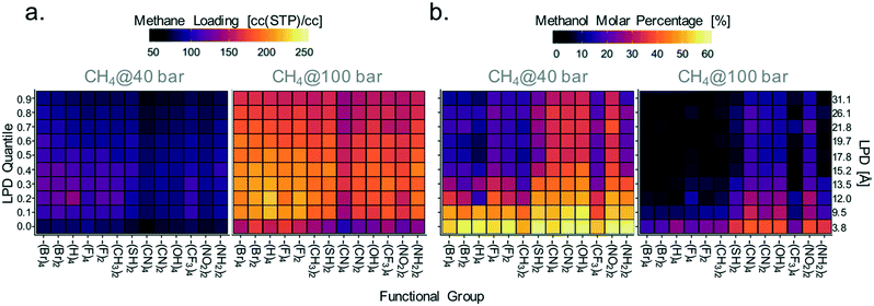
Accordingly, given the importance of electrostatic interactions as a driving force for methanol adsorption, materials exhibiting the highest methane loadings (suitable for the microtank core) should have not only large pores but also a relatively low concentration of moieties that electrostatically attract methanol. Conversely, materials with the lowest methane loadings (suitable for the microtank shell) should have a large concentration of such moieties. To associate these principles with specific MOF chemistries, we proceeded to calculate the average methane loading (relevant for core material selection) and molar concentration of methanol in the pores (relevant for membrane material selection) for each MOF linker functionality along 10 increasing quantiles of LPD. The quantiles cover LPD values from 3.8 to 31.1 Å. Results are plotted in Fig. 9 in the form of heat maps (maps for other pressures are shown in Fig. S10†), with the functional groups in the horizontal axis organized from left to right in the order of increasing maximum charge magnitude.
Although, consistent with the results in Fig. 8c–f, the variance in methanol loadings with MOF functionality (which alters electrostatic interactions) is not as pronounced, Fig. 9a shows that –Br, –H, –F, and –CH3 functionalized MOFs tend to have higher methane loadings than –SH, –CN, –OH, –CF3, –NO2, and –NH2 functionalized MOFs. This is more apparent for LPD values in the 12–14 Å range, which were shown to be optimal in Fig. 8. Again, notice that although electrostatic interactions do not affect methane adsorption directly, they do so indirectly by increasing methanol adsorption, in turn reducing the space for methane.
Variance in methanol molar concentrations was influenced more strongly by MOF functionality. Fig. 9b shows that MOF functionalization with –SH, –CN, –OH, –NO2, and –NH2, results, on average, in higher percent methanol molar concentrations in the pores than those seen in MOFs with less charged functional groups. The one exception is the –CF3 functional group, which presents low concentrations of methanol despite the relatively large charge on the carbon atom. It is plausible that because the carbon in –CF3 is shielded by less charged fluorine atoms, the interaction with methanol is weakened significantly. The largest average methanol molar concentrations are found for pore sizes less than 9.5 Å. It should be noticed that the functionalities studied here do not include all possible moieties that could provide the desired interaction with sealants such as methanol. For instance, the created 2000-MOF database does not include many synthetically attractive moieties such as thiazole, thiophene, and pyrazole moieties in heterocyclic linkers, which could also provide strong interactions with hydrophilic sealants.
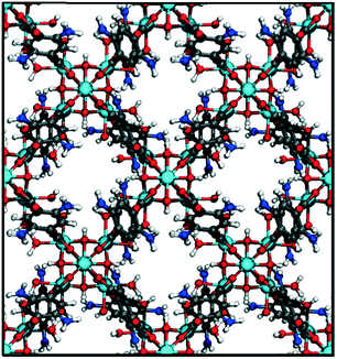
Finally, we visually inspected the MOF designs suitable to work as microtank components. Given that promising MOF designs for the shell are scarcer than for the core, here we focus the discussion on MOFs suitable for the shell. Fig. 10 shows an example MOF structure for which methanol concentration is 99.7% when methane pressure is 100 bar. This structure is based on the bcu topology and is assembled by combining 8-connected zirconium oxoclusters with ditopic benzoic dicarboxylic (BDC) acid linkers functionalized with amino groups (analogous structures with –NO2 and –CN functionalization present similarly high methanol concentration). The regular distribution of zirconium nodes indicates a structure with virtually no pore polydispersity (the LPD is 8.0 Å). Simulation snapshots (Fig. S11†) show that similar to snapshots in Fig. 5 for the idealized pores, methanol adsorption inside the pores is significantly driven by electrostatic interactions between methanol–OH groups and the hydrophilic pore moiety (–NH2 in this case). Other MOFs we inspected with similar methanol adsorption metrics shared similar features, namely, small monodisperse pores featuring –NH2, –NO2, –CN, and –OH groups.
It is critical to recognize that the synthetic challenges that microtank realization pose are more significant than for the synthesis of “stand-alone” MOFs. These challenges are more in line with those faced by MOF membrane synthesis in general, such as the compatibility of the membrane and the support (here, the shell and the core) so as to yield mechanically stable, crack-free membranes. In this study, we focused on the properties of the core and the shell individually, but synthetic challenges can be tackled by adding additional “filters” related to material compatibility to screen for promising core–shell pairs.
Conclusions
Based on our simulation results, we propose the following material design principles for nanoporous microtanks for methane storage: (i) the use of a hydrophilic sealant, (ii) the use of a hydrophobic core with monodisperse large pores, and (iii) the use of a hydrophilic membrane with monodisperse small pores. Upon loading with pure methane, both the core and the membrane would fill with methane. Once the sealant vapor is introduced, the sealant would completely displace the methane from the membrane, but not the core. Once the pressure is lowered, the pressurized methane in the core would not diffuse out because it cannot displace the hydrophilic sealant from the membrane pores. By inspecting a 2000-MOF database, we were able to evaluate how the above design principles translate into specific rules for identifying MOFs for microtank synthesis considering methanol as the sealant. We found that MOFs for the core should likely be based on unfunctionalized linkers, featuring pores between 12 and 14 Å, while MOFs for the shell should be based on small linkers functionalized with –NH2, –OH, –NO2 or –CN groups and featuring pore sizes smaller than 9 Å. The experimental challenges are (i) synthetically realizing the MOFs with the desired pore size and hydrophobicity/hydrophilicity characteristics as identified from simulations and (ii) coating the core material with the membrane material without any cracks. Simulations show that large pores, i.e. cracks, would likely adsorb methane even if the pore is hydrophilic. Simulations can help overcome these synthetic challenges by adding new criteria to the screening, such as the epitaxial and/or topological matching of promising core and shell materials as well as the similarity of thermal expansion coefficients which are important for membrane (the shell) growth on a support (the core).Conflicts of interest
There are no conflicts to declare.Acknowledgements
D. A. G.-G. acknowledges funding from the National Science Foundation CAREER Award (CBET 1846707). Calculations were made possible thanks to the Mio Supercomputer hosted and maintained by Colorado School of Mines. We also thank Aileen Le (A. L.) and Regan Parish (R. P.) for Fig. S5† and corresponding simulations. Z. P, M. S., A. L. and R. P. participated in this project as part of the Executive Internship Program for High School Students sponsored by Jefferson County, Colorado.References
- U.S. Energy Information Agency. How much natural gas does the United States have, and how long will it last? Available at: https://www.eia.gov/tools/faqs/faq.php?id=58&t=8, (Accessed: 15th September 2018).
- U.S. Department of Energy. Natural gas emissions. Available at: https://www.afdc.energy.gov/vehicles/natural_gas_emissions.html, (Accessed: 15th September 2018).
- J. A. Mason, M. Veenstra and J. R. Long, Evaluating metal–organic frameworks for natural gas storage, Chem. Sci., 2014, 5, 32–51 RSC.
- ARPA-E Methane Opportunities for Vehicular Energy(MOVE), 2012. Available at: https://arpa-e.energy.gov/?q=arpa-e-programs/move, (Accessed: 20th June 2019).
- U.S. Department of Energy. CNG Fuel System and Tank Maintenance. Available at: https://www.afdc.energy.gov/vehicles/natural_gas_cylinder.html, (Accessed: 15th September 2018).
- Office of Energy Efficiency and Renewable Energy. DOE Teams Up to Advance Naturals Gas Vehicle Research. Available at: https://www.energy.gov/eere/articles/doe-teams-advance-natural-gas-vehicle-research.
- T. Tian, et al., A sol–gel monolithic metal–organic framework with enhanced methane uptake, Nat. Mater., 2017, 17, 174 CrossRef PubMed.
- B. Li, H.-M. Wen, W. Zhou, J. Q. Xu and B. Chen, Porous Metal-Organic Frameworks: Promising Materials for Methane Storage, Chem, 2016, 1, 557–580 CAS.
- H. Furukawa, K. E. Cordova, M. O'Keeffe and O. M. Yaghi, The Chemistry and Applications of Metal-Organic Frameworks, Science, 2013, 341, 1230444 CrossRef PubMed.
- M. Eddaoudi, et al., Systematic Design of Pore Size and Functionality in Isoreticular MOFs and Their Application in Methane Storage, Science, 2002, 295, 469–472 CrossRef CAS PubMed.
- D. A. Gómez-Gualdrón, C. E. Wilmer, O. K. Farha, J. T. Hupp and R. Q. Snurr, Exploring the Limits of Methane Storage and Delivery in Nanoporous Materials, J. Phys. Chem. C, 2014, 118, 6941–6951 CrossRef.
- A. W. Thornton, et al., Materials Genome in Action: Identifying the Performance Limits of Physical Hydrogen Storage, Chem. Mater., 2017, 29, 2844–2854 CrossRef CAS PubMed.
- D. A. Gómez-Gualdrón, et al., Impact of the strength and spatial distribution of adsorption sites on methane deliverable capacity in nanoporous materials, Chem. Eng. Sci., 2017, 159, 18–30 CrossRef.
- Y. Peng, et al., Methane Storage in Metal–Organic Frameworks: Current Records, Surprise Findings, and Challenges, J. Am. Chem. Soc., 2013, 135, 11887–11894 CrossRef CAS PubMed.
- H.-M. Wen, et al., A Metal–Organic Framework with Optimized Porosity and Functional Sites for High Gravimetric and Volumetric Methane Storage Working Capacities, Adv. Mater., 2018, 30, 1704792 CrossRef PubMed.
- Z.-L. Shi and Y.-B. Zhang, Renaissance of the Methane Adsorbents, Isr. J. Chem., 2018, 58, 985–994 CrossRef CAS.
- J.-M. Lin, et al., A Metal–Organic Framework with a Pore Size/Shape Suitable for Strong Binding and Close Packing of Methane, Angew. Chem., Int. Ed., 2016, 55, 4674–4678 CrossRef CAS PubMed.
- D. Alezi, et al., MOF Crystal Chemistry Paving the Way to Gas Storage Needs: Aluminum-Based soc-MOF for CH4, O2, and CO2 Storage, J. Am. Chem. Soc., 2015, 137, 13308–13318 CrossRef CAS PubMed.
- C.-C. Liang, et al., Engineering of Pore Geometry for Ultrahigh Capacity Methane Storage in Mesoporous Metal–Organic Frameworks, J. Am. Chem. Soc., 2017, 139, 13300–13303 CrossRef CAS PubMed.
- Z. Song, et al., Nanovalved Adsorbents for CH4 Storage, Nano Lett., 2016, 16, 3309–3313 CrossRef CAS PubMed.
- K. L. Tate, S. Li, M. Yu and M. A. Carreon, Zeolite adsorbent-MOF layered nanovalves for CH4 storage, Adsorption, 2017, 23, 19–24 CrossRef CAS.
- B. Chen, J. J. Potoff and J. I. Siepmann, Monte Carlo Calculations for Alcohols and Their Mixtures with Alkanes. Transferable Potentials for Phase Equilibria. 5. United-Atom Description of Primary, Secondary, and Tertiary Alcohols, J. Phys. Chem. B, 2001, 105, 3093–3104 CrossRef CAS.
- M. G. Martin and J. I. Siepmann, Transferable Potentials for Phase Equilibria. 1. United-Atom Description of n-Alkanes, J. Phys. Chem. B, 1998, 102, 2569–2577 CrossRef CAS.
- A. K. Rappe, C. J. Casewit, K. S. Colwell, W. A. Goddard and W. M. Skiff, UFF, a full periodic table force field for molecular mechanics and molecular dynamics simulations, J. Am. Chem. Soc., 1992, 114, 10024–10035 CrossRef CAS.
- R. Anderson and D. A. Gómez-Gualdrón, Increasing topological diversity during computational “synthesis” of porous crystals: how and why, CrystEngComm, 2019, 21, 1653–1665 RSC.
- Y. J. Colón, D. A. Gómez-Gualdrón and R. Q. Snurr, Topologically Guided, Automated Construction of Metal–Organic Frameworks and Their Evaluation for Energy-Related Applications, Cryst. Growth Des., 2017, 17, 5801–5810 CrossRef.
- S. Plimpton, Fast Parallel Algorithms for Short-Range Molecular Dynamics, J. Comput. Phys., 1995, 117, 1–19 CrossRef CAS.
- S. L. Mayo, B. D. Olafson and W. A. Goddard, Dreiding: a generic force field for molecular simulations, J. Phys. Chem., 1990, 94, 8897–8909 CrossRef CAS.
- E. Argueta, et al., Molecular Building Block-Based Electronic Charges for High-Throughput Screening of Metal–Organic Frameworks for Adsorption Applications, J. Chem. Theory Comput., 2018, 14, 365–376 CrossRef CAS.
- L. D. Gelb and K. E. Gubbins, Pore Size Distributions in Porous Glasses: A Computer Simulation Study, Langmuir, 1999, 15, 305–308 CrossRef CAS.
- D. Dubbeldam, S. Calero, D. E. Ellis and R. Q. Snurr, Raspa: molecular simulation software for adsorption and diffusion in flexible nanoporous materials, Mol. Simul., 2016, 42, 81–101 CrossRef CAS.
- J. A. Mason, et al., Methane storage in flexible metal–organic frameworks with intrinsic thermal management, Nature, 2015, 527, 357 CrossRef CAS PubMed.
- M. Alhamami, H. Doan and C.-H. Cheng, A Review on Breathing Behaviors of Metal-Organic-Frameworks (MOFs) for Gas Adsorption, Materials, 2014, 7, 3198–3250 CrossRef PubMed.
- T. Kundu, B. B. Shah, L. Bolinois and D. Zhao, Functionalization-Induced Breathing Control in Metal–Organic Frameworks for Methane Storage with High Deliverable Capacity, Chem. Mater., 2019, 31, 2842–2847 CrossRef CAS.
Footnotes |
| † Electronic supplementary information (ESI) available: Simulation methodology. Simulated pure component isotherms. Simulated DMB/methane mixture isotherms. Simulation snapshots. CIFs for pore models and MOFs. Excel spreadsheet with high-throughput screening data. See DOI: 10.1039/c9me00072k |
| ‡ By preferentially we are not referring to adsorption selectivity as it would be traditionally calculated: N1/y1/N2/y2, where Ni is the adsorbed loading and yi is the gas phase composition of component i. Rather, we are simply referring to what compound is more prominent in the adsorbed phase within the pores. |
| This journal is © The Royal Society of Chemistry 2020 |


![[thin space (1/6-em)]](https://www.rsc.org/images/entities/char_2009.gif) 915 Pa).
915 Pa).