
 Open Access Article
 This Open Access Article is licensed under a Creative Commons Attribution-Non Commercial 3.0 Unported Licence
Hybrid perovskite crystallization from binary solvent mixtures: interplay of evaporation rate and binding strength of solvents†
Oleksandra
Shargaieva
*a,
Hampus
Näsström
 a,
Joel A.
Smith
b,
Daniel
Többens
c,
Rahim
Munir
d and
Eva
Unger
*a
a,
Joel A.
Smith
b,
Daniel
Többens
c,
Rahim
Munir
d and
Eva
Unger
*a
aHelmholtz-Zentrum Berlin für Materialien und Energie GmbH, Young Investigator Group ‘Hybrid Materials Formation and Scaling’, Kekulestr. 5, 12489 Berlin, Germany. E-mail: oleksandra.shargaieva@helmholtz-berlin.de; eva.unger@helmholtz-berlin.de
bUniversity of Sheffield, Department of Physics & Astronomy, Sheffield S3 7RH, UK
cHelmholtz-Zentrum Berlin für Materialien und Energie GmbH, Department of Structure and Dynamics of Energy Materials, Albert-Einstein-Str. 15, 12489 Berlin, Germany
dUniversity of Calgary, Chemistry Department, 2500 University Dr NW, AB T2N 4V8, Calgary, Canada
First published on 2nd November 2020
Abstract
In this work, we rationalize the chemical pathways and kinetics of the crystallization of methylammonium lead iodide hybrid perovskite. Our approach includes a combination of analysis of solvent coordination, the structure of intermediate solvate phases, and modeling evaporation rates of precursor solutions. The evolution of solution species via intermediate solvate phases and into perovskite thin films during drying was monitored by in situ grazing-incidence wide-angle X-ray scattering (GIWAXS). All studied precursor solutions exhibited the formation of intermediate solvate phases including a previously unreported GBL phase. In single-solvent solutions, crystallization kinetics are determined by the solvent evaporation rate and saturation concentration required for nucleation. In binary solvent mixtures, the evaporation rate of solutions is dominated by the most volatile solvent which leads to unequal evaporation of the components of the mixture. The structure of the intermediate phases in such systems strongly depends on the coordination strength and the availability of solvents upon nucleation. The combined approach described in this work allows predicting the kinetics and the chemical pathways of crystallization of hybrid perovskites in complex solvent mixtures. This insight is of great importance for future perovskite ink design.
Introduction
Hybrid perovskites are one of the most attractive materials for the future generation of low-cost solar energy conversion devices. A critical aspect that has caused the rapid progress of hybrid perovskites is the ability to achieve high-efficiency photovoltaic devices with a variety of deposition methods.1–3 Solution-based deposition methods such as spin-coating, inkjet printing, blade-coating, spray-coating, and slot-die coating allow for low-cost and straightforward deposition of the material.4–7 Spin-coating is currently the most optimized method and has enabled record performance solar cells on a laboratory scale.8 However, current attempts to commercialize perovskite solar cells have been realized via inkjet printing, yielding 16.1% power conversion efficiency (PCE) for an 802 cm2 module area.9Spin-coated perovskite devices with the highest PCEs often employ precursor solutions with a complex solvent combination and various quenching approaches to induce crystallization that have been developed empirically.1,10,11 Adaptation of these approaches to large-scale deposition techniques typically does not yield the desired result; as, for instance, quenching becomes technologically difficult at large scale.12,13 Therefore, rationalized usage of solvent blends is required to control material crystallization to obtain homogeneous high-quality materials. Ink engineering for conventional solution deposition techniques often includes multiple solvents and additives that modify chemical and physical properties of the ink, such as solubility, solvent–solute interaction, rheology, and drying kinetics of the ink (Scheme 1). Hybrid perovskite precursor materials show adequate solubility in polar aprotic solvents with rheological parameters appropriate for most deposition methods.14,15 Therefore, understanding and controlling solvent–solute interaction and drying kinetics is critical for controlled material formation in all solution-processing techniques.
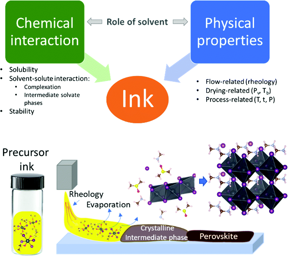 | ||
| Scheme 1 Role of solvent in hybrid perovskite precursor ink. | ||
The interaction between solvent and hybrid perovskite precursors significantly affects all processes occurring during perovskite formation (Scheme 1). In the first stage, solvent–solute interactions allow for the dissolution of the precursor materials.16 In the next stage, interactions of the dissociated ions with solvent leads to the formation of polyhalido plumbate complexes in solution.17 These complexes then act as building blocks for the formation of crystalline intermediate solvate phases that form during drying of the precursor solution or as a result of quenching.18 During the final stage, a crystalline intermediate phase transforms into a crystalline perovskite phase upon further solvent removal. Control over the kinetics of solvent removal and structure of the intermediate phases allows for better control over the process in general and the material quality in particular.19,20 Numerous reports have shown optimization of individual parameters such as crystallization via certain intermediate phases or change of processing parameters by using volatile solvents or vacuum.19,21–23 However, the complex role of solvents and co-solvents in hybrid perovskite precursor inks on intermediate phase structure and film formation kinetics is not yet well understood.
In this work, we establish a complex overview of the processes taking place during the crystallization of perovskite precursor solution. In particular, we link chemical interactions between the solvent and solute with the physical properties of solvents that define the crystallization process of hybrid perovskites. We demonstrate how an understanding of the interplay between coordination strength of a solvent and evaporation rates of precursor solutions enables prediction of the predominant hybrid perovskites intermediate solvate phases and the kinetics of their formation from mixed solvents.
Experimental
Solution preparation
Solutions of methylammonium lead iodide (MAPbI3) in dimethylformamide (DMF), gamma-butyrolactone (GBL), dimethylsulfoxide (DMSO) and N-methylpyrrolidone (NMP) were prepared by dissolving dry methylammonium iodide (MAI) and PbI2 powders with 1![[thin space (1/6-em)]](https://www.rsc.org/images/entities/char_2009.gif) :1 molar ratio in anhydrous solvents in N2 atmosphere. As-purchased anhydrous GBL was dried additionally over molecular sieves. The solutions were shaken at 60 °C for 12 h. For the preparation of binary solvent mixtures, equal volumes of corresponding fully dissolved single solvent precursor solutions were mixed after shaking at 60 °C for 12 h. Before usage the solutions were cooled down to room temperature.
:1 molar ratio in anhydrous solvents in N2 atmosphere. As-purchased anhydrous GBL was dried additionally over molecular sieves. The solutions were shaken at 60 °C for 12 h. For the preparation of binary solvent mixtures, equal volumes of corresponding fully dissolved single solvent precursor solutions were mixed after shaking at 60 °C for 12 h. Before usage the solutions were cooled down to room temperature.
In situ GIWAXS
For in situ grazing-incidence wide-angle X-ray scattering (GIWAXS), 5 μL of 1 M MAPbI3 solution was dispensed and spread uniformly by blade-coating on a clean glass substrate placed on an Anton Paar heating stage at T = 28 °C in N2 flow (6 L h−1). Next, a graphite dome was attached to the heating stage over the sample. The stage was connected to a dry nitrogen bottle with 6 L h−1 flow of N2 and 50 mbar overpressure valve on the outlet of the stage, as shown in Fig. 1. The configuration of the rotating detector and the KMC-2 beamline at the BESSY II electron storage ring is described in detail in Többens et al.24 Radiation energy of 8048 eV, wavelength 1.5406 Å, equivalent to Cu Kα1, and flux, f = 1011 photon s−1 mm−2 was used. The incidence angle was one degree. One diffraction pattern frame was collected every 14.2 seconds. The first frame was acquired 60 s after the liquid was dispensed. Three temperature steps with various durations were used during the experiment: 28, 40, and 100 °C. The temperature of the stage was recorded for each GIWAXS frame. To ensure the quality of the diffractograms and for alignment, LaB6 was measured as a calibrant. | ||
| Fig. 1 Schematic representation of the experiment. | ||
Absorbance measurements
The MAPbI3 solutions in DMSO, DMF, NMP, and GBL were measured in a 10 μm path quartz cuvette. To avoid saturation of the detected spectra, the concentration of the solutions was reduced to 0.1 M.Results and discussion
Crystallization of MAPbI3 from single solvent ink
The crystallization of MAPbI3 solutions from single solvent precursor solutions (inks) was monitored by in situ grazing-incidence wide-angle X-ray scattering (GIWAXS) with synchrotron radiation. Integrated GIWAXS patterns of 1 M methylammonium lead iodide (MAPbI3) precursor solutions in DMF, GBL, DMSO, and NMP are shown in Fig. 2 as a function of drying time. | ||
| Fig. 2 2D contour plots of azimuthally integrated GIWAXS patterns of MAPbI3 solutions in (a) DMF, (b) GBL, (c) DMSO, and (d) NMP as a function of drying time. The three temperature regimes used for all the experiments are shown in (a) (right axis) and marked throughout with dotted lines indicating 28, 40, and 100 °C temperature steps. The respective individual diffraction patterns of the intermediate phases are shown on the right. All experiments were performed with photon energy 8040 eV, closely matching Cu Kα radiation. | ||
The formation of initial amorphous solvate phases (sol–gel phase) can be observed as an increase of the intensity in the range of 5° to 8° 2θ during the early stages of the experiments.25 The initial solvate phase peak shifts over time to larger 2θ values, indicating a reorganization process, specifically a reduction of the characteristic distance between solute scattering centers as the solvent evaporates. As a result of this reorganization, the film approaches supersaturation and crystalline intermediate phases can be formed. Solutions of MAPbI3 in DMF (a) and GBL (b) form a crystalline intermediate phase at room temperature after 3 min 45 s and 5 min 45 s, respectively (Fig. 2). The diffraction peaks observed for the intermediate phase formed from DMF corresponds well to the crystal structure previously interpreted as (DMF)2(MA)2Pb3I8.26 The crystalline intermediate phase formed from GBL exhibits comparable diffraction peak positions as the (DMF)2(MA)2Pb3I8 phase. This observation is unexpected as the formation of a crystalline intermediate phase formed from GBL has been frequently suggested but has not yet been identified.27,28 The common failure to observe the diffraction pattern of the GBL–MAPbI3 intermediate phase during crystallization can likely be attributed to the presence of water (Fig. S1, ESI†). Nevertheless, comparing the molecular sizes of DMF and GBL, we find that their molecular dimensions are similar, with the longest dimension of the GBL molecule being only 0.07 Å larger than DMF. The coordination interaction with the lead-halide lattice is also expected to be comparable via the carbonyl group and lone-pairs on the adjacent oxygen or nitrogen. Similar dimensions and bonding interactions suggest that DMF and GBL are incorporated in similar lattice positions, creating crystalline solvate phases with negligible difference in lattice dimensions. The similarity of crystallization kinetics between DMF and GBL also indicates the similarity of their physical properties related to crystallization, e.g. vapor pressure, Pv (see Table 1).
| Solvent | P v of MAPbI3(solv)/Pa (28 °C) | R evap /mol m−1 s−1 (28 °C) | t cryst/min | N solv start | N solv cryst |
|---|---|---|---|---|---|
| DMF | 596 | 3.51 × 10⁻⁶ | 3.75 | 12.9 | 8.8 |
| GBL | 402 | 2.36 × 10⁻⁶ | 5.75 | 13 | 8.9 |
| NMP | 110 | 5.93 × 10⁻⁷ | 46.18* | 10.36 | 2.5 |
| DMSO | 88 | 5.36 × 10⁻⁷ | 74.93* | 14.15 | 2.5 |
Films coated from solutions in DMSO and NMP only show the formation of the amorphous solvate phase at low temperatures, with the crystalline phase formed during the 100 °C annealing step (Fig. 2c and d). This observation correlates with the lower volatility of these solvents in comparison to DMF and GBL. The values of the calculated initial vapor pressure (at the beginning of the experiment) of perovskite precursor solutions are listed in Table 1.29
To observe the crystallization of perovskite solutions in DMSO and NMP before 100 °C annealing, the same in situ drying experiments were also conducted over a longer time scale, see Fig. S2 (ESI†). The onset of crystallization of MAPbI3 from both NMP and DMSO at room temperature was notably delayed to 46 min 10 s and 74 min 56 s, respectively. The intermediate phase formed in DMSO correlates well with the previously reported (DMSO)2(MA)2Pb3I8 phase.30 For NMP, the formation of a crystalline intermediate phase was indicated by a diffraction peak at 2θ = 8.2°, similarly to previously reported.27,31,32 The diffraction patterns of the intermediate phases in the extended 2θ range are shown in Fig. S3 (ESI†).
To further quantify the difference in the crystallization onsets, we have calculated the evaporation rates, REvap, for these solvent systems as a function of time using an evaporation model described in detail in the ESI.† The REvap values obtained for the MAPbI3 solutions at the beginning of the experiment are listed in Table 1. Using these evaporation rate values the change in the concentration of the solutions due to the evaporation can be estimated. Combining this with the experimentally determined crystallization onset time (tcryst), we can estimate the number of solvent molecules per lead halide unit (PbIn), Nsolv, at the moment of crystallization (see Table 1). Here we find that Nsolv at the moment of crystallization is greater for solvents with higher evaporation rates, such as DMF and GBL, whilst both NMP and DMSO undergo more solvent evaporation before crystallization, despite almost an order of magnitude lower REvap.
The vast difference in Nsolv can be related to the different evaporation rates or different interactions between solvent and precursors in a solution. First, let us consider the different evaporation behavior in the solvent systems. Typically, rapid evaporation of a solvent leads to a rapid increase of the solution concentration. In cases where the evaporation rate is higher than the diffusion of the solvent molecules through the wet film that is required for the material solvation, nucleation can occur spontaneously, even if a large amount of solvent is present in other parts of the film. However, if the evaporation rate is slower than the diffusion of the molecules in the solution, the concentration of the material can gradually reach values greater than the solubility limit at a given temperature without nucleation occurring, satisfying conditions for supersaturation. Since supersaturated solutions are metastable, the nucleation can then occur upon a perturbation of the system due to, for example, an increase of the evaporation rate (see Fig. S2, ESI†T = 40 °C).
Considering the interactions in the liquid state, solvent–solute coordination in hybrid perovskite precursor solutions leads to the formation of solution complexes that often dictate the nature of intermediate phases. Solvents with different chemical and physical properties show different affinity to perovskite precursor ions, mainly Pb2+ and I−.33 The higher affinity of the solvent to Pb and I hinders the interaction of the ions between each other, thus, promoting the formation of solution species with a larger number of coordinated solvent molecules (Pb2+Solv6, PbI+Solv5, and PbI2Solv4).34 Conversely, the lower affinity of the solvent molecule to Pb and I facilitates stronger interaction between Pb and I, which in turn leads to the formation of high-order polyiodide plumbates (PbI3−Solv3 and PbI42−Solv2). It has been suggested that high number of coordinated iodine might have a beneficial influence on the transformation of intermediate phases to perovskite and the morphology of the films.35
To obtain information about the strength of the solvent–solute interactions in solution, absorbance spectra were measured in various solvents. Fig. 3 shows the absorbance spectra of 0.1 M MAPbI3 solutions in DMSO, DMF, NMP, and GBL.
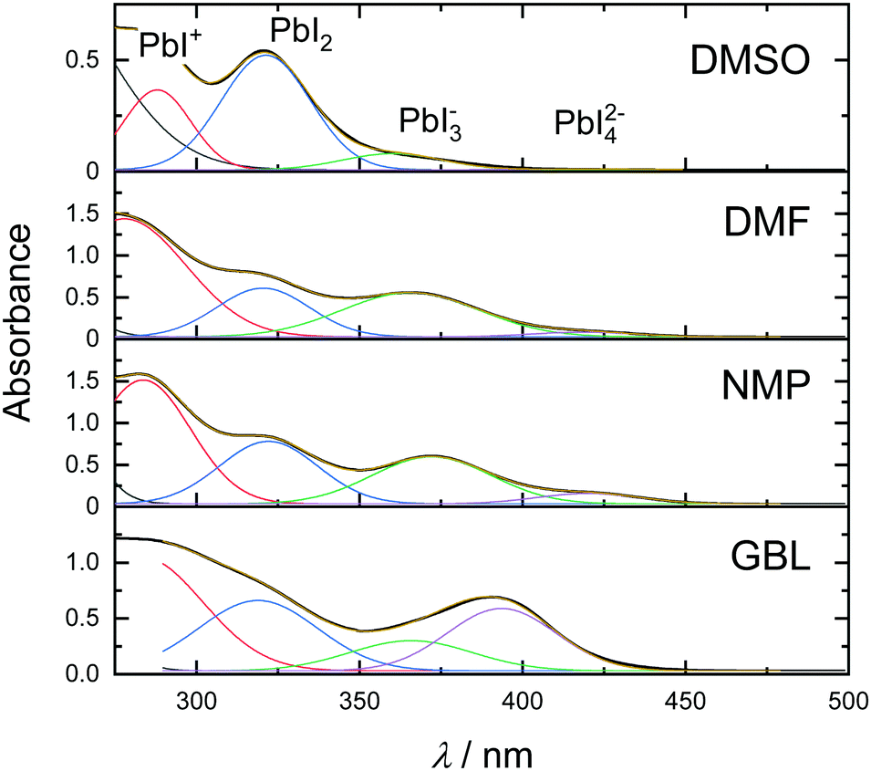 | ||
| Fig. 3 (a) Absorbance spectra of MAPbI3 solutions in DMSO, DMF, NMP, and GBL. | ||
Absorption bands corresponding to the above-mentioned polyiodide plumbates are noted in the top panel. As can be seen in Fig. 3, the solution of perovskite in DMSO exhibits absorption bands at 288, 321, and 363 nm that correlate with the presence of PbI+Solv5, PbI2Solv4, and only a small amount of PbI3−Solv3. Exchanging the solvent for DMF leads to a dramatic increase in the concentration of PbI3−Solv3 in the solution and even formation of PbI42−Solv2 species. A similar effect with an even higher concentration of PbI42−Solv2 species can be seen in the NMP solution. Furthermore, the solution of MAPbI3 in GBL exhibited the highest concentration of PbI3−Solv3 and PbI42−Solv2 species of all solvents at this precursor concentration. The absorption bands ascribed to PbI3−Solv3 and PbI42−Solv2 species showed a shift in the peak position, which can possibly indicate further formation of higher-order polyiodide plumbates or iodoplumbate chains.36 The increased amount of higher-order polyiodide plumbates indicates that the strength of solvent coordinating ability to MAPbI3 increases in order from GBL to DMSO (GBL < NMP < DMF < DMSO). Interestingly, this order of solvents in relation to perovskite coordination ability correlates well with the theoretically predicted trend, calculated through a sum of Gutmann's donor and acceptor numbers.37 Importantly, the formation of coordination species in all solvents correlates well with the fact that all solvents exhibited intermediate phase formation. On the other hand, this trend does not correlate with the experimental crystallization onset (Fig. 2). This observation indicates that at the early stages of solvent evaporation, solvent–solute interactions do not show a dramatic influence on solvent evaporation kinetics. Instead, the kinetics of hybrid perovskite crystallization is predominantly regulated by the physical properties of the solvent at the early stages of film drying.
Crystallization of MAPbI3 from binary solvent mixtures
To further corroborate the influence of evaporation rates and solvent–solute interaction on the structure and crystallization onset, 1 M MAPbI3 solutions in binary mixtures of DMF, GBL, NMP, and DMSO in 50:50% v/v were studied. Interestingly, the diffraction patterns of the intermediate phases formed from both DMF:DMSO and GBL:DMSO binary mixtures correspond to the structure of the pure DMSO intermediate phase, independent of the presence of DMF and GBL (Fig. 4a and d-g1, g2) as previously reported.38 Similar behavior is observed for the mixture of NMP and GBL (Fig. 4 e), with the intermediate phase formed in this mixture corresponding to the structure formed from pure NMP (Fig. 4-h2). However, in the DMF: NMP mixture, the presence of the stronger-binding DMF leads to a distortion of the predominant NMP intermediate structure due to interactions between and with both solvents (Fig. 4b-h1). This distortion is shown by the appearance of an initial diffraction peak at a higher 2θ (8.27°), which can be attributed to the smaller size of the DMF molecule in comparison to NMP. This peak then evolves into the peak at 8.18°, typical for the pure NMP intermediate structure (Fig. S4, ESI†).27,31,32 Likewise, the binary mixture of DMF and GBL exhibited the formation of a new intermediate phase at 28 °C due to the similarly high Pv of both solvents in the mixture. The integrated GIWAXS pattern from the DMF:GBL intermediate structure shows peaks at 6.6°, 8.07°, and 9.6° that correlate with the peaks of DMF and GBL intermediate phases, as well as additional peaks at 7.25° and 9.24° that do not. This observation indicates that in this case, the symmetry of the formed intermediate phase is affected by both solvents. The binary mixture of NMP and DMSO, on the other hand, showed delayed crystallization with the appearance of only weak reflections before annealing at 100 °C, similarly to pure DMSO and NMP solvent precursor solutions (Fig. 4f). The peak positions of the weakly scattering intermediate phase formed from this mixture appear to correlate with those of the pure DMSO intermediate indicated by the asterisk in Fig. 4-h3. GIWAXS detector images of MAPbI3 solutions coated from pure solvents and binary solvent mixtures as a function of time are shown in Fig. S6 and S7, ESI† respectively.
 | ||
| Fig. 4 2D contour plots of integrated GIWAXS patterns from MAPbI3 solutions in 50:50% v/v of (a) DMF:DMSO, (b) DMF:NMP, (c) DMF:GBL, (d) GBL:DMSO, (e) GBL:NMP, and (f) NMP:DMSO as a function of drying time. Dotted lines indicate the beginning of a new temperature regime with the temperatures noted above the figures. The diffraction patterns of the intermediate crystalline phases of MAPbI3 formed in pure and mixed solvents are shown in (g) and (h). Yellow and red lines in (a)–(f) indicate the calculated volumes of corresponding solvents in the solvent mixtures over time (scale is shown on the right axis). | ||
Binary mixtures of solvents consisting of DMF:DMSO, DMF:NMP, GBL:DMSO and GBL:NMP exhibited significantly different crystallization onset times compared to the pure solvent precursor solutions (Fig. 4a, b, d and e). In these mixtures, despite the presence of 50% v/v of low Pv solvents (DMSO, NMP) in the mixture, the crystallization occurred after 20 min 24 s in DMF:DMSO at 28 °C, 21 min 12 s in DMF: NMP at 28 °C, 23 min 30 s in GBL:DMSO at 40 °C and after 24 min 18 s in GBL: NMP mixture at 40 °C. These vast differences in the crystallization onset can be rationalized through the calculation of the total vapor pressure and evaporation rates of the binary mixtures. Typically, the total vapor pressure of a system can be calculated using Raoult's law, where the total pressure is a function of the composition of the liquid phase. In reality, the total vapor pressure of a mixture consisting of two components (A, B) in a vapor-liquid equilibrium depends on the difference between the properties of the components and their interaction. In the simplified case, where molecular interactions between solvent molecules are negligible, a positive deviation from ideal behavior can be observed if the ratio of the vapor pressures φ = p0B/p0A > 1 or negative deviation if φ < 1. The positive deviation from ideal linear behavior indicates that the molar fraction of component A in the vapor phase, yA, is higher than the molar fraction of A in the liquid phase xA. In other words, the vapor phase evaporating from such a mixture is enriched with the A component that has a higher vapor pressure, p0A, at given conditions, whilst the liquid phase is enriched with the less volatile B component. This change in the composition of the vapor and liquid phases dramatically influences the total vapor pressure of the system, which in turn influences the evaporation of the solvent mixtures.
In the case of mixtures of DMF with DMSO and NMP φ > 1, since p0DMF > p0DMSO and p0NMF (Table 1), thus, the vapor phase of both mixtures is dominated by DMF even when 50% v/v of solvents is used. This leads to an increase of the initial REvap values of DMF:DMSO and DMF: NMP to 1.96 × 10⁻⁶ and 2.20 × 10⁻⁶ mol m−1 s−1, respectively, close to REvap for pure DMF (Table S1, ESI†). Similarly, mixtures of GBL with both NMP and DMSO showed REvap values of about 1.5 × 10⁻⁶ mol m−1 s−1. Complete values for all mixtures are listed in Table S1 (ESI†). From this, we conclude that high evaporation rates at the beginning of the experiment lead to a more rapid saturation of the solution and accelerated crystallization onset in comparison with pure DMSO and NMP. On the other hand, evaporation of the more volatile solvent (e.g., DMF) with a higher rate leads to its quick depletion in the liquid phase, as shown in Fig. S5 (ESI†) for all solvent mixtures. Removal of the volatile solvent from the solution increases the probability of the solvent–solute interactions with the less volatile solvent molecules, independent of their binding strength. Therefore, the structure of the intermediate phase upon onset of crystallization can be determined by the stoichiometry of the solvents at the point of crystallization, not only the solvent coordination.
Taking into account calculated evaporation rates and the composition of vapor and liquid phases, we can calculate the amount of each solvent at different stages of the experiment. The volume of each of the components in the mixtures is shown in Fig. 4a–f. As can be seen from the graphs, the solutions consist of predominantly DMSO or NMP when either is present at the moment of crystallization. In the mixture of DMSO with DMF or GBL, the structures of the respective intermediate phases are similar to the pure DMSO intermediate ((DMSO)2(MA)2Pb3I8 phase), since coordination to DMSO is stronger than DMF and GBL, and their concentration in the solution is reduced in comparison to DMSO. In the case of the DMF and NMP mixture, the inclusion of the more strongly binding DMF in the NMP intermediate phase is limited mainly by the very low concentration of DMF in the mixture and the peak indicating its incorporation disappears with prolonged evaporation of DMF (Fig. S4, ESI†). On the other hand, when evaporation rates of components in a binary solvent mixture are similar and both solvents are available for interaction, the structure which forms will be influenced by both solvents, as in the case of the GBL and DMF mixture (Fig. 4c). Thus, our results imply that the hybrid perovskite crystallization kinetics and the intermediate structure can be manipulated through careful choice of solvents in the precursor ink by their coordination strengths and evaporation rates.
It is important to note that this model can be considered valid only for free solvent evaporation. Our observations of coordination in solution, as well as observed intermediate phases formed during crystallization, indicate that not all solvent molecules are free in the perovskite precursor solution. The observed intermediate phases that can be correlated with previously reported structures include two molecules of solvent per Pb3I8 unit (Nsolv = 0.667). Other reported structures indicate a 1:1 solvent:Pb ratio ((DMF)(MA)3PbI5, (DMF)2(MA)2Pb2I6) that translates to a molar fraction of xsolv = 0.5 or Nsolv = 1.26 Since, perovskite precursor solutions contain on average 10 times more solvent than perovskite (xsolv ≈ 0.925, Nsolv ≈ 10), any solvent that is evaporated before crystallization can be considered free solvent. Therefore, when considering liquid films before crystallization, our approach can be used for predicting kinetics of crystallization and estimating possible intermediate phases of hybrid perovskites in mixed solvent systems. Since the interaction of the perovskite precursors with solvents mainly affects the structure of the intermediate phases, this approach can be generalized for the estimation of the kinetics of the crystallization of other compositions of hybrid perovskites deposited with scalable methods such as blade-coating, slot-die coating, or inkjet printing.
Conclusions
In this work, we demonstrate how knowledge of coordination species and modelling the evaporation behavior of precursor solutions allows us to rationalize the crystallization processes for various MAPbI3 perovskite solvent systems. In all pure solvents (DMF, GBL, DMSO, and NMP), we observed the interaction of perovskite precursors with solvent molecules, which led to the formation of corresponding crystalline intermediate phases. For the first time we show the formation of GBL intermediate phase. The kinetics of the crystallization in such systems heavily depends on the physical properties of the solvent and correlates well with calculated evaporation rates. In binary mixtures of solvents, competitive interactions from both solvents are observed. Due to the difference in evaporation rates of solvents in such mixtures, however, the interaction with precursors is limited by the availability of the solvent molecules at the moment of nucleation. Thus, the formation of an intermediate phase consisting of solvents with different coordination strengths is possible when both solvents are present, as in the case of DMF:GBL and DMF: NMP. As a result, we here rationalize why specific intermediate phases form and how the process window can be adjusted by choice of solvent mixtures. This approach can be useful for the development of processes where the formation of desired intermediate phases can be achieved via selective removal of the solvent prior to nucleation through control over the evaporation rates, as in the case of DMF and DMSO. This also will be of great importance when designing hybrid perovskite inks for large-scale reproducible manufacturing.Conflicts of interest
There are no conflicts to declare.Acknowledgements
O. S. and E. U. acknowledges funding from the German Science Foundation (DFG) provided in the framework of the priority program Grant No. SPP 2196, “Perovskite semiconductors: From fundamental properties to devices.” H. N. acknowledges funding from the German Ministry of Education and Research (BMBF) for the Young Investigator Group Hybrid Materials Formation and Scaling (HyPerFORME) within the program “NanoMatFutur” (grant no. 03XP0091) as well as the support from the HyPerCells graduate school and HI-SCORE research school. J. A. S. thanks EPSRC and Prof. David Lidzey for PhD studentship funding via CDT-PV (EP/L01551X/1), Erasmus for funding and Antonio Abate for hosting him at HZB. The use of beamtime at synchrotron beamline KMC-2, BESSY II, Berlin is gratefully acknowledged.References
- N. J. Jeon, J. H. Noh, Y. C. Kim, W. S. Yang, S. Ryu and S. Il Seok, Nat. Mater., 2014, 13, 897–903 CrossRef CAS.
- R. Swartwout, M. T. Hoerantner and V. Bulović, Energy Environ. Mater., 2019, 2, 119–145 CrossRef CAS.
- L. K. Ono, M. R. Leyden, S. Wang and Y. Qi, J. Mater. Chem. A, 2016, 4, 6693–6713 RSC.
- N. Ahn, D.-Y. Son, I.-H. Jang, S. M. Kang, M. Choi and N.-G. Park, J. Am. Chem. Soc., 2015, 137, 8696–8699 CrossRef CAS.
- S. G. Li, K. J. Jiang, M. J. Su, X. P. Cui, J. H. Huang, Q. Q. Zhang, X. Q. Zhou, L. M. Yang and Y. L. Song, J. Mater. Chem. A, 2015, 3, 9092–9097 RSC.
- K. Hwang, Y. S. Jung, Y. J. Heo, F. H. Scholes, S. E. Watkins, J. Subbiah, D. J. Jones, D. Y. Kim and D. Vak, Adv. Mater., 2015, 27, 1241–1247 CrossRef CAS.
- Z. Yang, C. C. Chueh, F. Zuo, J. H. Kim, P. W. Liang and A. K. Y. Jen, Adv. Energy Mater., 2015, 5, 1500328 CrossRef.
- M. A. Green, E. D. Dunlop, J. Hohl-Ebinger, M. Yoshita, N. Kopidakis and A. W. Y. Ho-Baillie, Prog. Photovoltaics Res. Appl., 2020, 28, 3–15 CrossRef.
- Panasonic claims 16.1% efficiency for lightweight perovskite solar module, https://na.panasonic.com/us/green-living/panasonic-claims-161-efficiency-lightweight-perovskite-solar-module, (accessed 29 May 2020).
- Y. Rong, Z. Tang, Y. Zhao, X. Zhong, S. Venkatesan, H. Graham, M. Patton, Y. Jing, A. M. Guloy and Y. Yao, Nanoscale, 2015, 7, 10595–10599 RSC.
- G. Wu, H. Li, J. Cui, Y. Zhang, S. Olthof, S. Chen, Z. Liu, D. Wang and S. Liu, Adv. Sci., 2020, 7, 1903250 CrossRef CAS.
- F. Guo, S. Qiu, J. Hu, H. Wang, B. Cai, J. Li, X. Yuan, X. Liu, K. Forberich, C. J. Brabec and Y. Mai, Adv. Sci., 2019, 6, 1901067 CrossRef.
- G. Jang, H. Kwon, S. Ma, S. Yun, H. Yang and J. Moon, Adv. Energy Mater., 2019, 9, 1901719 CrossRef.
- A. Giuri, E. Saleh, A. Listorti, S. Colella, A. Rizzo, C. Tuck and C. Esposito Corcione, Nanomaterials, 2019, 9, 582 CrossRef CAS.
- A. Giuri, S. Masi, A. Listorti, G. Gigli, S. Colella, C. Esposito Corcione and A. Rizzo, Nano Energy, 2018, 54, 400–408 CrossRef CAS.
- J. Stevenson, B. Sorenson, V. H. Subramaniam, J. Raiford, P. P. Khlyabich, Y.-L. Loo and P. Clancy, Chem. Mater., 2017, 29, 2435–2444 CrossRef CAS.
- S. J. Yoon, K. G. Stamplecoskie and P. V. Kamat, J. Phys. Chem. Lett., 2016, 7, 1368–1373 CrossRef CAS.
- B. J. Foley, J. Girard, B. A. Sorenson, A. Z. Chen, J. Scott Niezgoda, M. R. Alpert, A. F. Harper, D. M. Smilgies, P. Clancy, W. A. Saidi and J. J. Choi, J. Mater. Chem. A, 2017, 5, 113–123 RSC.
- Y. Deng, C. H. Van Brackle, X. Dai, J. Zhao, B. Chen and J. Huang, Sci. Adv., 2019, 5, eaax7537 CrossRef CAS.
- M. Yang, Z. Li, M. O. Reese, O. G. Reid, D. H. Kim, S. Siol, T. R. Klein, Y. Yan, J. J. Berry, M. F. A. M. van Hest and K. Zhu, Nat. Energy, 2017, 2, 17038 CrossRef CAS.
- N. K. Noel, S. N. Habisreutinger, B. Wenger, M. T. Klug, M. T. Hörantner, M. B. Johnston, R. J. Nicholas, D. T. Moore and H. J. Snaith, Energy Environ. Sci., 2017, 10, 145–152 RSC.
- X. Li, D. Bi, C. Yi, J.-D. Décoppet, J. Luo, S. M. Zakeeruddin, A. Hagfeldt and M. Grätzel, Science, 2016, 8060, 1–10 Search PubMed.
- K. H. Hwang, S. H. Nam, D. I. Kim, H. J. Seo and J. H. Boo, Sol. Energy Mater. Sol. Cells, 2018, 180, 386–395 CrossRef CAS.
- D. M. Többens and S. Zander, J. large-scale Res. Facil. JLSRF, 2016, 2, 49 CrossRef.
- S. Lee, M. C. Tang, R. Munir, D. Barrit, Y. J. Kim, R. Kang, J. M. Yun, D. M. Smilgies, A. Amassian and D. Y. Kim, J. Mater. Chem. A, 2020, 8, 7695–7703 RSC.
- A. A. Petrov, I. P. Sokolova, N. A. Belich, G. S. Peters, P. V. Dorovatovskii, Y. V. Zubavichus, V. N. Khrustalev, A. V. Petrov, M. Grätzel, E. A. Goodilin and A. B. Tarasov, J. Phys. Chem. C, 2017, 121, 20739–20743 CrossRef CAS.
- A. G. Ortoll-Bloch, H. C. Herbol, B. A. Sorenson, M. Poloczek, L. A. Estroff and P. Clancy, Cryst. Growth Des., 2020, 20, 1162–1171 CrossRef CAS.
- S. A. Fateev, A. A. Petrov, V. N. Khrustalev, P. V. Dorovatovskii, Y. V. Zubavichus, E. A. Goodilin and A. B. Tarasov, Chem. Mater., 2018, 30, 5237–5244 CrossRef CAS.
- Handbook of Chemistry and Physics, ed. J. Rumble, CRC Press, 100th edn, 2019 Search PubMed.
- J. Cao, X. Jing, J. Yan, C. Hu, R. Chen, J. Yin, J. Li and N. Zheng, J. Am. Chem. Soc., 2016, 138, 9919–9926 CrossRef CAS.
- Y. Li, L. Zhi, G. Ge, Z. Zhao, X. Cao, F. Chen, X. Cui, F. Lin, L. Ci, J. Sun, D. Zhuang and J. Wei, Cryst. Growth Des., 2019, 19, 959–965 CrossRef CAS.
- Y. Jo, K. S. Oh, M. Kim, K. Kim, H. Lee, C. Lee and D. S. Kim, Adv. Mater. Interfaces, 2016, 3, 1500768 CrossRef.
- J. C. Hamill, J. Schwartz and Y.-L. Loo, ACS Energy Lett., 2018, 3, 92–97 CrossRef CAS.
- S. Rahimnejad, A. Kovalenko, S. Forøs, C. Aranda and A. Guerrero, ChemPhysChem, 2016, 17, 2795–2798 CrossRef CAS.
- A. Sharenko, C. Mackeen, L. Jewell, F. Bridges and M. F. Toney, Chem. Mater., 2017, 29, 1315–1320 CrossRef CAS.
- O. Shargaieva, L. Kuske, J. Rappich, E. L. Unger and N. H. Nickel, ChemPhysChem, 2020, 21, 2327–2333 CrossRef CAS.
- J. C. Hamill, J. Schwartz and Y.-L. Loo, ACS Energy Lett., 2018, 3, 92–97 CrossRef CAS.
- Y.-H. Seo, E.-C. Kim, S.-P. Cho, S.-S. Kim and S.-I. Na, Appl. Mater. Today, 2017, 9, 598–604 CrossRef.
Footnote |
| † Electronic supplementary information (ESI) available. See DOI: 10.1039/d0ma00815j |
| This journal is © The Royal Society of Chemistry 2020 |