
 Open Access Article
 This Open Access Article is licensed under a Creative Commons Attribution-Non Commercial 3.0 Unported Licence
Formation of liquid marbles & aggregates: rolling and electrostatic formation using conductive hexagonal plates†
Benjamin T.
Lobel
 a,
Junya
Fujiwara
b,
Syuji
Fujii
cd,
Casey A.
Thomas
a,
Peter M.
Ireland
a,
Erica J.
Wanless
a and
Grant B.
Webber
*a
a,
Junya
Fujiwara
b,
Syuji
Fujii
cd,
Casey A.
Thomas
a,
Peter M.
Ireland
a,
Erica J.
Wanless
a and
Grant B.
Webber
*a
aPriority Research Centre for Advanced Particle Processing and Transport, University of Newcastle, Callaghan, NSW 2308, Australia. E-mail: grant.webber@newcastle.edu.au
bDivision of Applied Chemistry, Graduate School of Engineering, Osaka Institute of Technology, 5-16-1 Omiya, Asahi-ku, Osaka 535-8585, Japan
cDepartment of Applied Chemistry, Faculty of Engineering, Osaka Institute of Technology, 5-16-1 Omiya, Asahi-ku, Osaka 535-8585, Japan
dNanomaterials Microdevices Research Center, Osaka Institute of Technology, 5-16-1 Omiya, Asahi-ku, Osaka 535-8585, Japan
First published on 29th October 2020
Abstract
Conductive polymer coatings were successfully adsorbed to hexagonal polyethylene terepthalate plate surfaces after silane coupling and sulfonation were performed to promote intermolecular adhesion. Conducting particle coatings were verified via scanning electron microscopy observation, contact angle and conductivity measurements. The original substrates and newly modified platelet particles were used to form liquid marbles and aggregates through both the traditional rolling and electrostatic transfer methods of water droplet encapsulation. These two methods were then compared for stability and efficacy. In the rolling method, liquid marbles or aggregates were successfully fabricated using the PET plates with and without conducting polymer coating. In the electrostatic transfer method, the uncoated particles were unable to be extracted from the particle bed. Conversely, coated conductive particles were readily transferred to a pendent droplet, thereby stabilising it. Stability of these liquid marbles was also investigated at various stages of this coating process. In addition to this, the force of extraction was calculated using the field model of Morrison allowing for calculation of the interparticle forces in the particle bed, demonstrating that interparticle forces, rather than gravity, dominate the resistance to particle transfer.
Introduction
Hydrophobic (particle contact angle θ > 90°) spherical or sphere-like particles are traditionally used to form liquid marbles.1–4 These intriguing structures are liquid droplets encapsulated by particles and are thermodynamically stable due to the replacement of a high energy liquid–vapour interface with lower energy liquid–solid and solid–vapour interfaces.1,5–10 These liquid marbles have been proposed for use in a wide variety of research and industrial arenas including in microfluidics,11 cosmetics,12 as microreactors13,14 and in biomedical applications.15–17 These applications are due to their unique properties such as substantial elasticity, gas permeability, ability to be transported along a substrate with little friction and their ability to be transported across a liquid–vapour interface with no loss of the internal liquid, whilst demonstrating a diminished rate of evaporation.2,5,6,9,10,17,18 Despite spheres being historically used to stabilise these droplets, there has been some exploration in the use of platelet particles, specifically fluorinated bentonite and sericite, to stabilise primarily oil droplets as opposed to aqueous ones.19,20 More recently, however, large platelets have been demonstrated to be able to stabilise aqueous droplets, resulting in so-called polyhedral liquid marbles.21 This new type of liquid marble is interesting as the particles form a monolayer coating, reducing the amount of material needed for successful interface stabilisation. Furthermore, once formed these structures have demonstrated an ability to form larger macro-structures when physically pushed together.21Traditionally, liquid marbles stabilised by spherical particles, and these novel polyhedral liquid marbles, are formed by gently rolling the droplet on a bed of particles and allowing them to spontaneously affix to the drop interface.1,4–6 However, this method can be quite slow and risks coalescence of droplets if contact is made before sufficient stabilisation takes place. In recent years an alternative method of liquid marble formation has been reported, utilising an electric field.22–24 This process features contactless delivery of the particles to a pendent droplet and allows for substantial control of the droplet volume with no risk of coalescence. Furthermore, it allows for the use of hydrophilic particles to form particle-stabilised aggregates, where the particles are internalised in the droplet resulting in a metastable structure.25,26 Liquid marbles formed using this method are still able to retain all the applications and characteristics of traditional liquid marbles, whilst allowing for the possibility of scalability and formation of complex structures involving the internalisation of hydrophilic particles before encapsulation takes place with hydrophobic particles.25,27 However, some of the limitations of this particular method are that the particles must overcome interparticle forces, such as cohesion and friction in order to be extracted to the pendent droplet, which may be aided by increased conductivity and particle size.22,23,28 To this end, the viability of relatively large conductive platelets, compared to those previously studied,22,23,28 to stabilise a droplet will be investigated.
Here we present the synthetic coating of polyethylene terephthalate (PET) hexagonal plates with conductive polypyrrole29,30 (PPy) doped with hydrophobic dopant carrying perfluoroalkyl group (C8F) by aqueous chemical oxidative polymerisation followed by dopant change. In this method an intermediary silanisation step is required for significant PPy adhesion, increasing the potential diversity of core or substrate particles that may be modified with a conductive shell coating. Specifically, if a substrate is able to undergo the surface silanisation step, then PPy adhesion and the addition of a conductive layer should be possible. Previously, PPy coated particles doped with the same dopant has been observed to be light responsive, where irradiation with a NIR laser was able to induce locomotion of the LM on the liquid–vapour interface.31,32 Furthermore, the water evaporation rates of liquid marbles stabilised with polystyrene particles coated with the same PPy and dopant can be tuned by IR irradiation.33 The platelet particles herein would retain this characteristic whilst exploiting the unique geometry of the polyhedral liquid marbles as potential actuators and liquid delivery vessels.21,34 These newly synthesised coatings will be investigated with respect to their viability as liquid marble stabilisers using both the traditional rolling1,4,21 and the contactless electrostatic method of liquid marble formation, during which their electrostatic transfer behaviour will be investigated.22,23,25,28,35
Materials & methods
Sample preparation
Transparent polyethylene terephthalate (PET) hexagonal plates (Nakajima Metal Leaf & Powder Co., Ltd) of nominal vertex to vertex width (2S) 0.2, 1 and 2 mm were used as the sample substrate following washing with ethanol as previously reported.21 Surface modification began with a silane coupling reaction in order to add epoxide functionality to the plate surfaces. Briefly, PET (50.0 g) plates were placed in isopropanol (120 g, Sigma-Aldrich) containing 3-glycidoxypropyltriethoxysilane (0.3 g, Shin-Etsu Chemical Co., Ltd) and allowed to stir for 30 min at 35 °C, followed by evaporation of the isopropanol medium using an evaporator at 35 °C.After the evaporation of isopropanol, the plates were left to dry completely at room temperature under vacuum (45.9 Pa) for 24 h and then dispersed once more in isopropanol, followed by washing via filtration. The plates were then dried for 24 h at room temperature, followed by being dried in an oven at 80 °C for 24 h. These silane modified particles (PET-SCA plates, 40 g) were dispersed in aqueous solution of NaHSO3 (4.67 g, Wako in 120 g water, Advantec MFS RFD240NA), and were then heated in an oil bath for 6 h at 70 °C under a nitrogen atmosphere to open the epoxide ring and to introduce sulfonate (SO3−) groups to the surfaces (PET-SCA–SO3− plates).36,37 The resulting PET plates were then purified by medium change using water (10 times). Next, a PPy coating was added as previously reported.31,38 The PET-SCA–SO3− plates (30 g) were dispersed in aqueous solution of pyrrole (0.6 g, Sigma-Aldrich, in 240 g water), followed by addition of aqueous solution of FeCl3·6H2O (5.64 g, Wako, 60 g water) and allowed to stir for 24 h at room temperature to obtain PET–PPy–Cl plates. The resulting black plates were purified by medium changes (20 times) using water. Finally, a dopant change was performed in order to increase the particle hydrophobicity.28,31 PET–PPy–Cl (10 g) were dispersed in water (80 g), and then heptadecafluorooctane sulfonic acid (C8F, 0.496 g added as 40 wt% aqueous solution (1.24 g), Sigma-Aldrich) was added to the dispersion and allowed to stir for 24 h at room temperature to obtain PET–PPy–C8F plates. The resulting plates were washed by medium change using water (5 times). This process was performed for all three sizes of hexagonal plates and is summarised in Fig. 1.
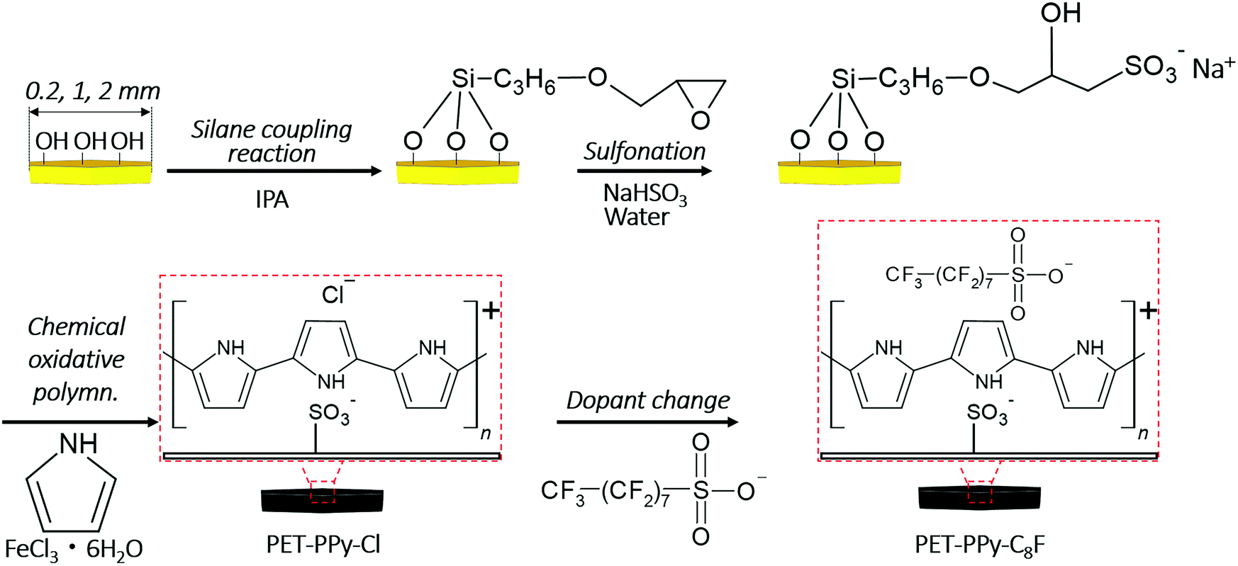 | ||
| Fig. 1 Diagram of full synthetic protocol for synthesis of PET–PPy–Cl and PET–PPy–C8F plates including silane coupling and sulfonation reactions at platelet surface. | ||
Sample characterisation
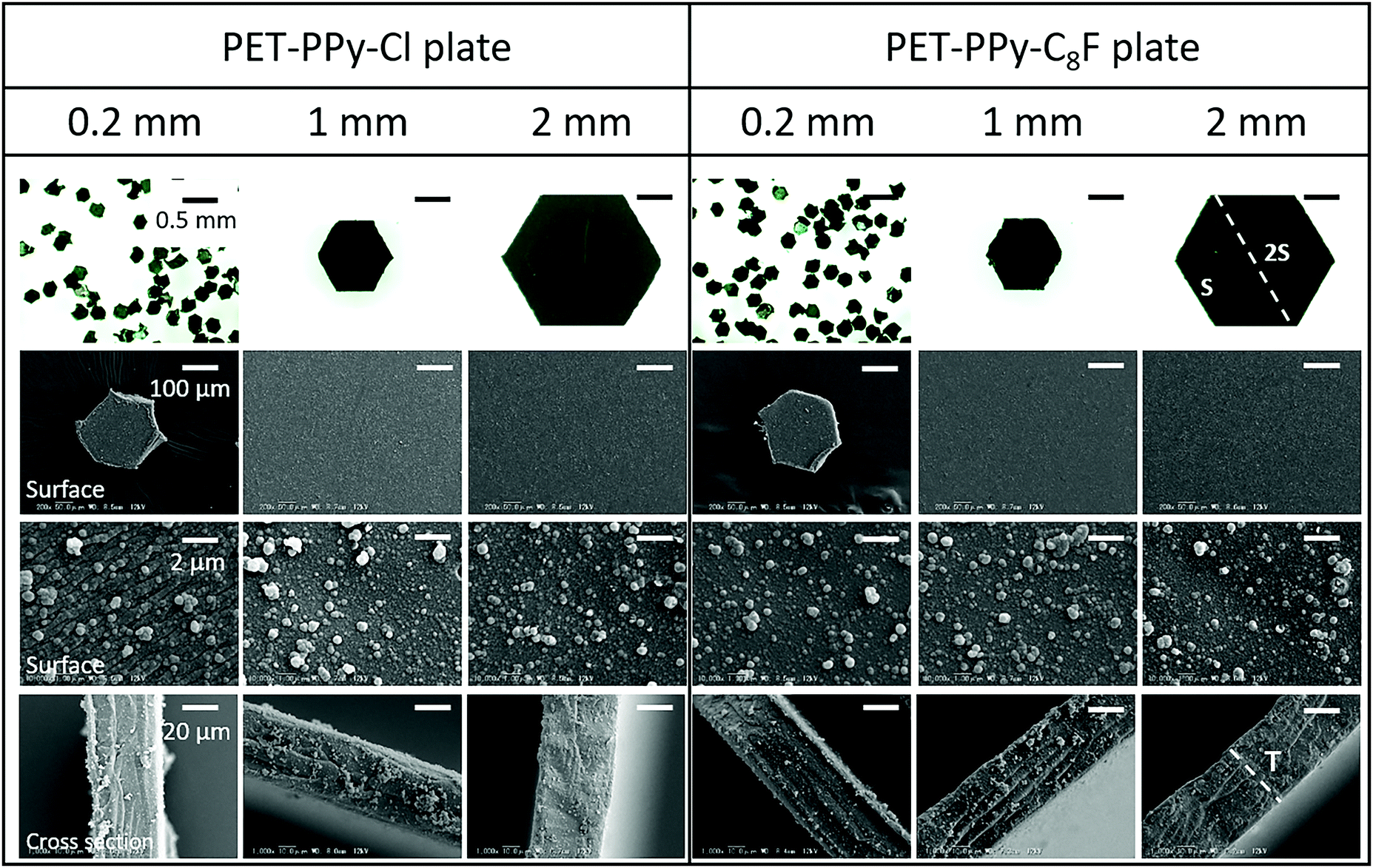 | ||
| Fig. 2 Stereo (top row) and scanning electron microscopy images showing successful coating of PET particles with conductive PPy coating and their dimensions for both dopants. 2S is the vertex to vertex width of the particle and T is the platelet thickness of 40 ± 5 μm for all plates. Left: PET–PPy–Cl. Right: PET–PPy–C8F. Scale bars are consistent for each row. | ||
| PET plate | PET–PPy–Cl coating | PET–PPy–C8F coating | |||||||
|---|---|---|---|---|---|---|---|---|---|
| Nominal size (mm) | Actual size (2S) ± 10% (mm) | Mass (kg) | Density (kg m−3) | Volume (%) | Mass (%) | Mass (kg) | Density (kg m−3) | Volume (%) | Mass (%) |
| 0.2 | 0.24 | 2.2 × 10⁻⁹ | 1450 | 1.7 | 1.7 | 2.19 × 10⁻⁹ | 1460 | 1.7 | 1.7 |
| 1 | 1.14 | 4.9 × 10⁻⁸ | 1430 | 1.3 | 1.4 | 4.56 × 10⁻⁸ | 1440 | 1.3 | 1.4 |
| 2 | 2.40 | 2.2 × 10⁻⁷ | 1430 | 1.2 | 1.2 | 2.17 × 10⁻⁷ | 1440 | 1.2 | 1.3 |
| Sample | Conductivity (× 10−2 Ω−1 cm−1) | Contact angle (°) |
|---|---|---|
| a Taken from literature.48 b Conductivity below the range of the instrument. | ||
| PET | Less than 1 × 10⁻¹²![[thin space (1/6-em)]](https://www.rsc.org/images/entities/char_2009.gif) a a |
72.4 ± 2.8 |
| PET-SCA | Less than 1 × 10⁻⁶b |
81.7 ± 1.8 |
| PET-SCA–SO3− | Less than 1 × 10⁻⁶b |
76.3 ± 1.2 |
| PET–PPy–Cl | 6.8 ± 2.4 | 23.3 ± 2.5 |
| PET–PPy–C8F | 3.6 ± 0.9 | 102.1 ± 1.2 |
Rolled liquid marble method
Rolled liquid marbles were prepared in the same manner as previously reported.21 Briefly, particles were placed in a perfluoroalkoxy alkane Petri-dish (Sanplatec) which had been surface abraded with an abrasive paper (WTCC-S CC100-Cw, Nihonkenshi Co., Ltd) in order to form a rough surface and diminish substrate wetting during the coating process. 15 μL water droplets were placed on a bed of each sample of the PPy coated PET plates and gently rolled using pipette tips (00-BMT2-SG, Nichiryo Co. Ltd) along the surface allowing the particles to affix to the air–water interface. Following the coating of the particles they were able to be moved to a different substrate using a plastic spoon and images taken with both a digital camera (Model G700SE; 5.0× optical zoom lens, Ricoh, Tokyo, Japan) and stereo microscope.Electrostatic drop coating experiments
Electrostatic particle coating of pendent water droplets was carried out following the same regime as previously reported.22,23,25,28,35 An electrically-earthed 5 μL pendent tap water droplet was positioned above a stainless steel plate, upon which a microscope slide with concave glass inset and bed of PET plates were mounted. The bed was prepared by placing a small quantity of platelets on the slide. The slide was then gently dropped on to a metal substrate from a height of approximately 5 mm, repeated ten times in order to impart a degree of uniformity between particle beds and to encourage particles to lie flat (horizontal) on the slide (see Fig. S4 for representative photos, ESI†). This steel plate was connected to a high voltage power supply (Spellman Bertan) and mounted on a motorised stage (Thorlabs). Once negative potential was applied to the stage it was moved towards the pendent droplet at a rate of 0.05 mm s−1 until either the pendent droplet was detached or contacted the particle bed. The conductive metal plate induces an opposite charge in the pendent droplet resulting in an attractive force between the particles and the droplet. This was performed at applied potentials between 0.5 and 3.0 kV at 0.5 kV intervals. A fresh droplet was pumped from a syringe pump (Harvard Apparatus) for each experiment. The two variables which determine the strength of this electrostatic force are the applied voltage and the separation distance between the droplet and the particle bed and metal plate. As the voltage increases so does the electric field strength. Conversely, a decrease in the drop-bed separation distance increases the electrostatic field strength in the region beneath the droplet. Furthermore, as a result of this increase in field strength, the charge on the particles themselves is also increased.39–41 Electrostatic transfer of the PET plate samples to the pendent drop interface as the particle bed approached was assessed visually on a Panasonic GH5 camera equipped with a Micro-Nikkor 105 mm f/2.8 lens at 50 fps. Analysis was performed by extracting relevant still images from the videos and measuring the distance between the particle bed and pendent droplet when significant particle transfer occurred using Adobe Creative Cloud Suite. This is henceforth referred to as the drop-bed separation distance. Charge transfer was measured via the addition of an electrometer (Keithley 6514) into the grounding circuit of the needle.Results & discussion
Polymer plates
In order for the polymer plates to work as an effective liquid marble stabiliser, the surface of the plates should be hydrophobic. Additionally, it has been demonstrated that liquid marbles could be easily fabricated using particles with an electrically conductive surface using the electrostatic method. We therefore first synthesised hydrophobic polymer plates coated by electroconductive PPy overlayers for evaluation of both formation methods.In addition to the obvious change from transparent to black, indicating the successful PPy coating, the PPy coating may clearly be observed on the surface of the PET plates confirming the successful synthesis. The SO3− groups on the surface effectively act as the PPy dopant allowing for a strong binding for the PPy overlayer to the PET plate.42 Once this initial binding takes place the Cl− dopant generated from the FeCl3 is able to act on the PPy both in bulk and on the surface groups that formed during the polymerisation. This results in the structures visible on the surface in Fig. 2 which is PPy that was produced in the bulk solution and adsorbed to the platelet surface, as reported in previous PPy substrate coating syntheses.43,44 These structures are not present on the uncoated PET platelets.
PPy coating thickness was determined by SEM imaging and a volume and mass percentage of the coating relative to the PET substrate calculated (Table 1). Figures and calculations used to determine coating characteristics may be found in the ESI† (Fig. S2, S3 and S5).
Once the hydrophobic heptadecafluorooctane sulfonic acid is added, the strong affinity of the sulfonic acid group to the PPy allows the replacement of the Cl− dopant with the C8F functionality resulting in increased hydrophobicity (Table 2). Given the mass percentage of pyrrole monomer relative to PET plate (2%) the majority of the added monomer appears to have been adsorbed to the PET plate surface and no significant amount of coating was lost during the dopant exchange. This demonstrates the importance of the addition of the sulfonation process during synthesis to ensure this strong binding to the PET surface whilst allowing the PPy surface to be further modified.
The colour change from clear white to an opaque black, the increase in conductivity observed for the PPy coated particles, as well as the variation in contact angle indicated the successful coating of the PET plates.4,29,30,45,46 The initial increase in contact angle of the PET-SCA plates is expected as the silane introduces additional hydrophobic groups to the platelet surface. Furthermore, the following decrease in contact observed in the PET-SCA–SO3− is also expected due to the increased polar and ionic interactions at the particle–liquid interface.8,47
Rolled marble experiments
First, both platelet samples coated by PPy–Cl and PPy–C8F overlayers were assessed for their ability to form liquid marbles via rolling of a water drop on a bed of particles. The PET–PPy–Cl plates did not appear to readily stabilise the interface and were wetted by a water droplet, which was likely due to the hydrophilic surface character of the particles (Table 2); water-particle aggregates were formed (Fig. 3). Plain PET plate liquid marbles were also attempted (Fig. S6, ESI†) via rolling, however due to the hydrophilic nature of the bare PET plates (θ < 90°), these were unstable.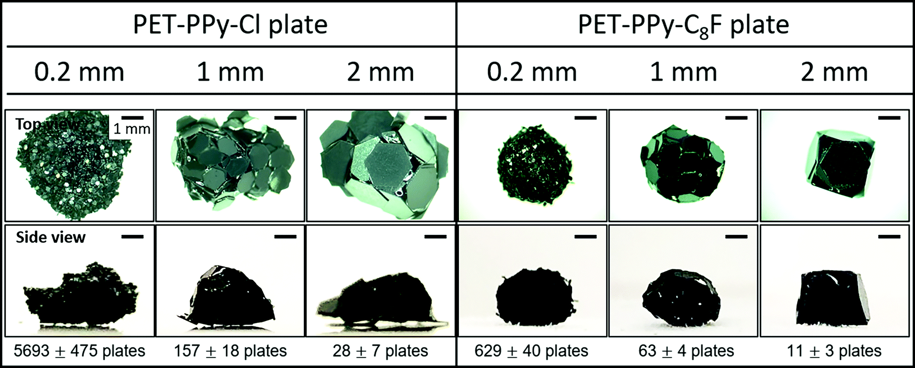 | ||
| Fig. 3 Representative images of 15 μL water droplets stabilised by PET–PPy–Cl and PET–PPy–C8F particles of increasing size after rolling on particle bed and approximate number of particles encasing the water droplet for each. The number of particles was determined by gravimetric analysis after water was allowed to evaporate from the rolled structures (Tables S1 and S2, ESI†). | ||
The 0.2 mm PET–PPy–Cl coated PET particles appeared to be wet relatively quickly and the liquid was absorbed into the particle bed resulting in a wet aggregate of particles, resembling a thick paste. In the cases of the 1 and 2 mm PET–PPy–Cl coated PET particles, wet aggregates with visible interstices of air–water interface were formed by rolling resulting in a “house of cards” morphology. Despite the large size of the platelet particle relative to the water droplet, the high rigidity of the PET plate resists the capillary force that could result in the folding of thin sheets known as the “capillary origami” effect, where the sheets are bent and folded to conform around a droplet by surface tension.21,49 Notwithstanding the hydrophilic particle surfaces, water pinning at the edge of each platelet particle prevented the water from enveloping the particles despite their low contact angle (Table 2). This is attributed to their unique geometry as the sharp edges of the particles require substantially more energy to be engulfed by water resulting in the previously described pinning. This phenomenon has been previously reported50,51 and is a result of the deformation of the three phase contact line, resulting in an increase in the observed surface tension force normal to the surface at the edge, and consequently the observed contact angle. Furthermore, it has been reported that this increase in force is proportional to the length of the edge in question, explaining the observed behaviour of the liquid on the hydrophilic platelets as they increased in size.50 In addition to this pinning, simple geometry plays a substantial role in this process. Given the constant size of the 15 μL droplet, as a 0.2 mm particle contacts the interface the droplet surface is large enough, and curvature sufficiently locally flat, that the entire particle is placed in wetting contact. However, as particle size increases, the curvature of the droplet begins to impact the contact area, resulting in only partial contact with the platelet and promoting the “house of cards” structure. Once these meta-stable aggregates were mechanically compressed using a finger, the water flowed out of the aggregate and spread, resulting in dispersion of particles in water (Fig. S7 and S8, ESI†).
Conversely, the PET–PPy–C8F particles with their hydrophobic surface were able to adsorb to the air–water interface to stabilise the droplet. The 0.2 mm particles most closely resembled a classic LM retaining the original droplet sphericity.1,4,52 This sphericity diminished as the particle size increased as observed for the 1 and 2 mm particles. This deviation from sphericity is due to the aforementioned geometric factors. This deformation is most obvious in the case of the 2 mm particles where the structure begins to resemble a regular convex polyhedron. However, despite the substantial amounts of exposed interstitial liquid, the structure was still able to retain structural integrity and be moved without any liquid loss, similar to those previously reported for fluorinated PET plates.21 In order to further explore the particle packing at the interface, the PET–PPy–C8F marbles were exposed to ethyl 2-cyanoacrylate (Aron Alpha Extra Sokkotayoto, Toagosei Co., Ltd) vapour to allow anionic polymerisation to take place once in contact with water, effectively locking the particle-shell in place.53 The structures retained their integrity during the subsequent drying process due to the high adsorption energy of the particles at the liquid–air interface.21 After drying, the retained structure was assessed via SEM imaging (Fig. 4).
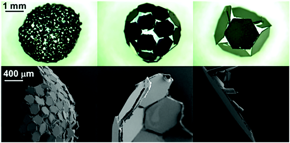 | ||
| Fig. 4 Images of PET–PPy–C8F particle shells after treatment with ethyl 2-cyanoacrylate vapour and drying. Top: Stereo Microscopy. Bottom: SEM. Left: 0.2 mm particles. Middle: 1 mm particles. Right: 2 mm particles. | ||
The SEM images demonstrate that all three PET–PPy–C8F particle sizes form a monolayer at the interface. The 0.2 mm particles sit at the interface and are somewhat varied in their orientation relative to the interface. Many of the particles lie along the interface, with some small interstices visible. Given the hydrophobic nature of the C8F dopant, this behaviour of sustained stability, despite incomplete coverage and concomitant exposure of the internal phase is a common feature observed in liquid marbles and was also observed with the previously studied fluorinated PET plates.5,21 In addition to this, a few of these particles are oriented with their narrow edge to the interface while still being able to stabilise the droplet; likely a result of their random orientation in the particle bed before rolling. Conversely, the larger 1 mm and 2 mm particles all lie along the interface, likely due to their large size and tendency to lie flat as coating takes place, maximising the reduction of the area of the liquid–vapour interface.6
Electrostatic experiments
Both PPy coated platelet samples, as well as the bare PET plates, were assessed for their transferability under an applied electric field to coat pendent water droplets or form electrostatic liquid marbles. The success of this was characterised by a complete coating of the droplet interface and the ability to contact the substrate without wetting, even whilst still attached to the needle. The uncoated PET and PET-SCA/SO3− particles were unable to be extracted from the bed under an applied electric field. The low conductivity of the uncoated PET plates allows for only dielectrophoretic extraction forces as opposed to the much stronger Coulombic force, diminishing the total extraction force placed on the particles.23,40,41,54 Conversely, the PPy coated particles were readily extracted from the particle bed (Fig. 5), due to their greater conductivity (Table 2); behaviour consistent with previous work examining the impact of particle conductivity on electrostatic particle extraction.22,28 Both sets of doped particles demonstrate a tendency to arrive at the droplet edge first. Due to the non-uniform packing in the particle bed and high aspect ratio geometry of the platelet particles, their edges are likely to protrude slightly from the bed allowing for charge to concentrate here, resulting in the particles becoming aligned with their plane parallel to the electric field and maintaining this orientation throughout the extraction and transfer process. Musinski et al. also noted this phenomenon in high aspect ratio particles, such as cylinders, which demonstrate a similar concentration of charge at their end when subjected to a simple uniform electric field.55 However, due to the difference in the wettability of their coatings, the behaviour once at the liquid–vapour interface is quite different.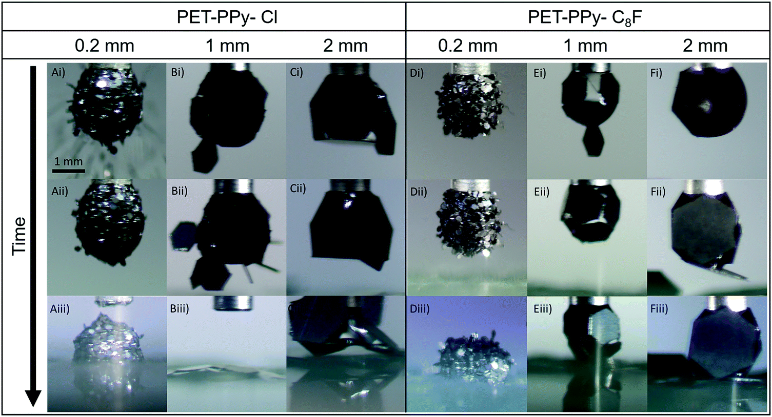 | ||
| Fig. 5 Extracted images from videos (Videos S1–S6, ESI†) of the electrostatic transport of platelets to a 5 μL pendent droplet at an applied potential of 2 kV for each size fraction and PPy coating. | ||
As mentioned above, the rolled method demonstrated that the hydrophilic PET–PPy–Cl platelets were unable to completely stabilise the liquid droplet. However, some meta-stability was observed due to the geometry and interfacial pinning at the platelet edge until external pressure was applied at which point the lack of true stability is made apparent (Fig. 3 and Fig. S6, ESI†). In the case of the electrostatic delivery process, the 0.2 mm platelets (Video S1, ESI†) tended to impact the droplet edge-first and then are drawn by capillary forces to lie flat along the liquid interface. Despite their low contact angle, however, they do not penetrate into the droplet resulting in a relatively smooth surface coating (Fig. 5A(i)). As this coating process continues, seemingly forming a multilayer of particles, the previously attached particles are apparently pushed into the droplet (Fig. 5A(ii)). Once contact is made with the glass substrate, the aggregate experienced sufficient electrostatic force that the entire structure was pulled from the needle and the contained water began to drain into the bed. However, some stability was retained as the meta-stable aggregate sat proud upon the substrate, likely due to the present internal particle structure (Fig. 5A(iii)).
As the particle size increases to 1 mm (Video S2, ESI†), the number of particles that can pack onto the interface is significantly reduced (Fig. 5B) and they are unable to reorient to lie flat at the droplet interface once several particles are already present. Furthermore, the increase in size allows for the observation of the expected charge concentration on the edges of the particles as they are delivered by their edge to the interface. In this case the capillary forces are able to hold the particles by their edge on the droplet surface (Fig. 5B(ii)). Despite this near-complete coverage of the interface, these particles are unable to stabilise the droplet and contact with the glass substrate (Fig. 5B(iii)) results in instant wetting and destruction of the aggregate. As the platelet size is increased once more to 2 mm (Video S3, ESI†) the behaviour changes again. After particles are delivered to the pendent droplet, their greater size means they tend to physically block any particles from attaching to the droplet after the majority of the available surface area is occupied (Fig. 5C(i)), significantly limiting the number of particles able to adsorb to the interface. Once the coated droplet comes into contact with the glass underneath, however, the liquid is neither able to wick out or engulf the particles. Instead, the droplet begins to deform as it is forced to increase the area of the solid–liquid interface, which was previously limited by the geometry and size of the particles compared to the droplet. Finally, the water once more becomes pinned at the platelet edge, unable to engulf the plate and instead deforms even further, trapped on the platelet surface (Fig. 5C(iii)). This is further demonstration of the substantial energy required to overcome the forces attributed to the sharp edge of the platelets, despite the low contact angle of the particles.50,51
The hydrophobic plates (PET–PPy–C8F) demonstrate different behaviour across all three sizes. This is expected due to their greater hydrophobicity and consequently greater ability to stabilise a water droplet and form a liquid marble, as observed in the rolling experiments above (Fig. 3). In the case of the 0.2 mm platelets (Video S4, ESI†), the particles tend to largely remain protruding from the drop at a non-zero angle, with the liquid unable to move around the platelet edge. This results in a much rougher appearance of the coated droplet (Fig. 5D(ii)) compared to the similar size PET–PPy–Cl system (Fig. 5A(ii)). In contrast to their hydrophilic counterparts the PET–PPy–C8F particles only demonstrate a single major transfer event with particles being unable to penetrate into the droplet due to their greater contact angle (Table 2). These particles were, however, the only sample able to fully form a stable liquid marble owing to the smaller particle interstices, greater hydrophobicity and full droplet coverage resulting in sufficient interface stabilisation (Fig. 5D(iii)).8
In the case of the 1 mm platelets (Video S5, ESI†), the tendency for the particles to be initially delivered edge-on is observed yet again (Fig. 5E(i)). After additional particle transfer the platelets are able to reorient themselves to lie flat at the interface, but for substantially different reasons than the hydrophilic particles. In this case, the particles tend to move up to the top of the droplet near the needle. The driving force behind this is the minimisation of the area of the liquid–vapour interface via replacement with a lower energy interface as seen in classical particle-interface behaviour.7,8 Here, the particles will attempt the maximise the surface area of the droplet that they can occupy, and this is achieved by moving to the top of the droplet (Fig. 5E(i) and (ii)). In the case of a sphere the point of particle attachment on the uniform surface makes little difference. However, in the case of a pendent droplet, especially once deformed by an electric field, the geometry is significantly different. In this latter case, the top of the droplet has minimal curvature and a negative curvature gradient exists between the base and top of the droplet. When the particle is placed at any point on the droplet, it is driven to maximise the contact area between the plate and the droplet, which may be found near the needle. This location is optimal, as opposed to the bottom of the droplet, and is most effective at reducing the energy at the interface. Once this area of the droplet is fully occupied, particles tend to be positioned gradually lower down the droplet to the point of maximum curvature. Cavallaro et al., examined particles moving due to a curvature gradient at an interface and reported that particles would be drawn to the point of maximum curvature.56 However, the investigated particles were significantly smaller than the interface curvature. In the case of the particles reported here the radius of curvature is in fact smaller than the particle length and the driving forces behind this mechanism are not present. Despite this relatively ordered configuration, the droplet is not able to be fully stabilised (Fig. 5E(iii)). In contact with the glass substrate and remaining particles in the bed, the marble retains its integrity. However, on removal from the needle it quickly becomes unstable and results in particles sitting on a puddle of water.
Finally, the 2 mm platelets (Video S6, ESI†) once more tend to adsorb to the interface before moving to the top of the droplet (Fig. 5F(i)), and only once this is covered, further adsorption is to the base of the drop (Fig. 5F(ii)). This occurs despite the field being most focussed at the base of the droplet, where due to the curvature of the drop and being the point at which the drop-bed separation distance is at a minimum the strongest attractive force is present.57 Similar to the 1 mm particles with the same coating, the structure is quite stable until removed from the needle where it no longer retains its structural integrity despite the hydrophobicity of the particles in question (Fig. 5F(iii)).
Although liquid marbles were not necessarily able to be formed in all cases, the ability of the particles to be extracted and their behaviour in transferring charge to the droplet reveal properties of both the electric field and the particle bed. For each studied applied potential and particle sample the drop-bed separation distance at which particles began to be extracted from the particle bed was measured (Fig. 6). At increasing applied potentials the electric field exerts a greater force on the particles.40,58 Similarly, as the drop-bed separation between the particles decreases, this force of extraction is increased further.22,23,28
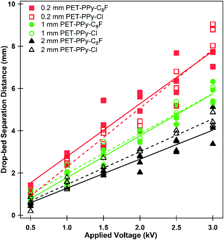 | ||
| Fig. 6 Drop-bed separation distance at which particles began to be extracted from the particle bed for each studied applied potential as the particle bed approaches the 5 μL pendent water drop at 0.05 mm s−1. Lines do not denote a physical relationship but are present to guide the eye. | ||
These measurements demonstrate the relative ease of extraction between studied particle samples. There appeared to be little difference in the ease of extraction of the PPy coated particles with different dopants (Fig. 6, compare closed and open data symbols), consistent with their similar conductivity, cohesion and surface area.28 These particles do, however, exhibit substantially different extraction behaviour to those previously studied.22,23 In previous work smaller spherical particles exhibited increased resistance to extraction when compared to large particles. This was inferred from the drop-bed separation when a particle first left the bed, which was attributed to a large number of interparticle contacts leading to greater particle bed cohesion.22–24 Here, however, the smaller particles are readily extracted at a relatively large distance while the larger particles required a much smaller bed-drop separation at a given voltage. This is due to the shape of the particles and their contact area which per particle is reduced in the case of a sphere compared to that of a platelet.22–24 It should be noted that these measurements do not indicate the only extraction event, as the process involved multiple individual extractions for all particle sizes (Videos S1–S6, ESI†). During the extraction process the particle bed undergoes multiple internal rearrangements. A relatively prominent particle on the top of the bed (Fig. S4, with lower contact area with other particles, ESI†) may be thought of as a weak link in the particle bed.26,59 This particle experiences a strong extracting force due to the concentration of charge, as well its (marginally) reduced distance to the pendent droplet relative to the other particles.23,40,55 Once this particle is extracted, adjacent particles are then in a state of reduced interparticle contact and further extraction is made possible, a cascading effect. As particles leave and are drawn to the bottom of the droplet, where the electric field is strongest, particles remaining in the bed may become jammed once more. This process is somewhat similar to non-free flowing particles being funnelled through a hopper. Furthermore, as the particle bed moves closer to the droplet, the lateral component of the electric field becomes stronger and subjects the particles to a compressive force, effectively increasing the interparticle cohesion and aiding particle jamming.26,57 This results in the seemingly intermittent character of the particle transfer process, which has been described in previous work.59 Further evidence of this phenomenon is described below.
 | ||
| Fig. 7 Magnitude of charge transferred to the water droplet as a consequence of PET–PPy particle transfer. Time is inversely proportional to bed-drop separation distance and is started when the particle bed began to move towards the droplet, the non-zero charge measured is due to the image charge as a result of the applied potential to the metal plate. (a) 0.2 mm PET–PPy–C8F, (b) 1 mm PET–PPy–C8F, (c) 2 mm PET–PPy–C8F and (d) 2 mm PET–PPy–Cl. Note that the electrometer is unable to record charge beyond 240 nC. | ||
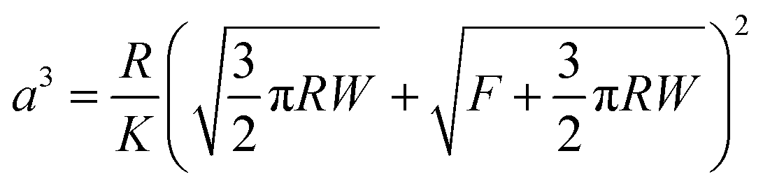
These charge transfer graphs clearly demonstrate the difference in the behaviour of the different platelet sizes. Once more, it is demonstrated via the measured charge transfer that the smaller particles are more readily extracted from the particle bed than the larger ones, as demonstrated by the earlier time, and therefore larger drop-bed separation distance, at a given potential where the first large increase in charge transfer is observed. Furthermore, the 0.2 mm particles (Fig. 7a) demonstrate the smallest amount of charge on each of the particles (Video S4, ESI† and Fig. 5) as the increases in charge registered by the electrometer are substantially smaller than those seen in the 2 mm particles (Fig. 7c and d) despite the large number of particles transferring to the droplet and the ability to form a multilayer structure. This is expected due to the dependence of charge acquired on a particle or platelet being a function of its surface area and the packing geometry of the larger particles at the interface.41 In the case of the 1 and 2 mm platelets their size allows for direct correlation between the charge increase and the number of particles transported; the size and transfer rate of the smaller 0.2 mm particles does not allow for an accurate account of the number of particles (Video S4, ESI†). The charge on each larger particle, q, can be determined by finding a point in the electrometer data where particle transfer occurs, and dividing the charge transferred in this event by the number of particles observed in the video to transfer. Once this charge per particle is known the electrostatic force acting on the particle at the moment of extraction can be calculated using a previously reported electrostatic field model,22,59 based on a model originally proposed by Morrison (Fig. S10, ESI†).57 This model is utilised to determine the electric field strength E (V m−1) (Table S3, ESI†) at the given applied potential and the experimentally measured drop-bed separation distance and then used in eqn (1):40
| Felectrostatic = qE | (1) |
| Felectrostatic ≥ Fmass + Finterparticle | (2) |
The results presented in Table 3 corroborate the findings of Fig. 6; the force required to extract a 1 mm platelet is substantially less than the 2 mm platelet. Furthermore, from Table 3 it is clear that gravitational forces are effectively negligible compared to the magnitude of the electrostatic force, from which it is possible to infer Felectrostatic ≅ Finterparticle. In addition to this, these interparticle forces appear to increase with particle size, which is contrary to what was found previously for spherical polymer particles treated with the same PPy and dopant coating and subjected to the same electrostatic extraction process.23 This is attributed to the difference in particle shape and subsequent contact area between particles. It should be noted however, that eventually as particle size increases, gravity will begin to become significant. Indeed 1 mm spherical PS/PPy–Cl particles were unable to be extracted in similar conditions. The hexagonal platelets reported here exhibit far larger contact areas than their spherical counterparts, both with the substrate and with respect to total interparticle contact. This increased contact area is further promoted by the gentle agitation of the platelets during bed preparation, which will result in the platelets lying horizontally along the plate, increasing their contact area. The area of two flat plates in contact may simply be taken as the surface area of one of its faces whilst the contact area of two spheres may be approximated using simple JKR contact mechanics.
 | (3) |
 | (4) |
| Particle | F electrostatic (mN) | F mass (mN) |
|---|---|---|
| 2 mm PET–PPy–Cl | 1.91 ± 0.45 | 2.13 × 10⁻³ |
| 2 mm PET–PPy–C8F | 2.99 ± 0.80 | 2.13 × 10⁻³ |
| 1 mm PET–PPy–C8F | 0.27 ± 0.16 | 4.47 × 10⁻⁴ |
Despite this calculation only accounting for a single sphere, it is not expected that even in a packed bed that the contact area for an individual sphere will increase by several orders of magnitude to match that of the equivalent platelet. Thus in order for a plate to experience the same contact area of a sphere of equivalent diameter, only a small fraction of the plate must be in contact with a neighbouring plate. This increase in surface area leads to an increase in both the adhesion forces to the glass substrate and the cohesion forces of the particles to one another resulting in the aformentioned inversion of the expected extraction order (Fig. 6), specifically that the smaller PET–PPy platelets are extracted more readily than the larger.47,60 Furthermore, the difference in the average extraction force demonstrated by the different PPy coatings is expected given the previously reported difference in cohesion, specifically the PPy–C8F being more cohesive than the PPy–Cl.28 The reason an increase in cohesion with size is not observed with spheres is due to the packing within the bed.23,24 For spheres, as particle size decreases the number of interparticle contacts increase in the particle bed. However, in the case of platelets there is no appreciable increase in contact area as the number of platelets increases. Furthermore, the greater particle size results in an increase in contact area with both the substrate and any underlying particles. This is due to their essentially two-dimensional nature. As more particles are added to the particle bed, there is no additional force or surface area occupied, adjacent particles are simply in contact with the edge of the particle. Simply put, the interparticle contact area in the case of the spheres is dependent on the number of spheres in the particle bed, and the number in direct contact which increases as particle size decreases. Conversely, the platelets are almost always at their maximum contact area either with the substrate or adjacent particles which increases as platelet size increases.
| Platelet size (mm) | Platelet contact area (mm2) | Sphere of equivalent diameter contact area (mm2) | Sphere of equivalent mass contact area (mm2) |
|---|---|---|---|
| 0.2 | 0.031 | 4.8 × 10⁻⁶ | 6.3 × 10⁻⁵ |
| 1.0 | 0.86 | 4.0 × 10⁻⁵ | 3.3 × 10⁻⁴ |
| 2.0 | 3.8 | 1.2 × 10⁻⁴ | 8.5 × 10⁻⁴ |
Conclusion
PPy with different dopants was successfully adsorbed to PET platelet substrates after treatment with an epoxide containing silane coupling agent and subsequent epoxide ring opening and formation of SO3− moiety. This allows the potential for any substrate demonstrating the tendency for silanisation to also become coated with conductive PPy. Confirmation of this synthesis was attained via microscopy, contact angle and conductivity measurements. These particles were then used to form liquid marbles via the traditional rolling method with some success, the more hydrophobic dopant allowing for the formation of a classic liquid marble. Following this, these same particles were transferred to a pendent droplet in order to form liquid marbles without direct contact using an electrostatic field. The formation of the marbles was not successful in this case, with the exception of the 0.2 mm particles but provided insight into the behaviour of large platelet particles delivered to a pendent drop via an electrostatic field. Specifically, that the electrostatic force is orders of magnitude larger than the weight of the particle, demonstrating that the interparticle forces are the dominant force resisting particle extraction. Furthermore, this interparticle force was shown to increase with particle size due to their platelet geometry and resulting contact area.Conflicts of interest
The authors have no conflicts to declare.Acknowledgements
This work was supported by Australian Research Council (DP170100578) and JSPS-OP (Australia) Bilateral Joint Research Projects and by a Grant-in-Aid for Scientific Research (B) (JSPS KAKENHI Grant Number JP20H02803). B. T. L. and C. A. T. both thank the Australian Government for their Research Training Program (RTP) scholarships.References
- P. Aussillous and D. Quéré, Nature, 2001, 411, 924–927 CrossRef CAS.
- P. Aussillous and D. Quéré, Proc. R. Soc. A, 2006, 462, 973–999 CrossRef CAS.
- P. McEleney, G. M. Walker, I. A. Larmour and S. E. J. Bell, Chem. Eng. J., 2009, 147, 373–382 CrossRef CAS.
- E. Bormashenko, Curr. Opin. Colloid Interface Sci., 2011, 16, 266–271 CrossRef CAS.
- E. Bormashenko, Langmuir, 2017, 33, 663–669 CrossRef CAS.
- G. McHale and M. I. Newton, Soft Matter, 2015, 11, 2530–2546 RSC.
- G. McHale and M. I. Newton, Soft Matter, 2011, 7, 5473–5481 RSC.
- B. P. Binks and T. S. Horozov, Colloidal Particles at Liquid Interfaces, Cambridge University Press, 2006 Search PubMed.
- S. Fujii, S. Yusa and Y. Nakamura, Adv. Funct. Mater., 2016, 26, 7206–7223 CrossRef CAS.
- P. Singha, C. H. Ooi, N.-K. Nguyen, K. R. Sreejith, J. Jin and N.-T. Nguyen, Microfluid. Nanofluid., 2020, 24, 81 CrossRef.
- C. H. Ooi and N. T. Nguyen, Microfluid. Nanofluid., 2015, 19, 483–495 CrossRef CAS.
- S. Yue, W. Shen and K. Hapgood, Adv. Powder Technol., 2016, 27, 33–41 CrossRef CAS.
- C. Fullarton, T. C. Draper, N. Phillips, B. P. J. de Lacy Costello and A. Adamatzky, J. Phys. Mater., 2019, 2, 015005 CrossRef CAS.
- X. Luo, H. Yin, X. Li, X. Su and Y. Feng, Chem. Commun., 2018, 54, 9119–9122 RSC.
- X. Fu, Y. Zhang, H. Yuan, B. P. Binks and H. C. Shum, ACS Appl. Mater. Interfaces, 2018, 10, 34822–34827 CrossRef CAS.
- T. Arbatan, L. Li, J. Tian and W. Shen, Adv. Healthcare Mater., 2012, 1, 80–83 CrossRef CAS.
- N. M. Oliveira, R. L. Reis and J. F. Mano, Adv. Healthcare Mater., 2017, 6, 1700192 CrossRef.
- C. Fullarton, T. C. Draper, N. Phillips, R. Mayne, B. P. J. de Lacy Costello and A. Adamatzky, Langmuir, 2018, 34, 2573–2580 CrossRef CAS.
- B. P. Binks, S. K. Johnston, T. Sekine and A. T. Tyowua, ACS Appl. Mater. Interfaces, 2015, 7, 14328–14337 CrossRef CAS.
- B. P. Binks, T. Sekine and A. T. Tyowua, Soft Matter, 2014, 10, 578–589 RSC.
- F. Geyer, Y. Asaumi, D. Vollmer, H.-J. Butt, Y. Nakamura and S. Fujii, Adv. Funct. Mater., 2019, 29, 1808826 CrossRef.
- B. T. Lobel, P. M. Ireland, L. M. Walsh, C. A. Thomas, G. B. Webber and E. J. Wanless, J. Phys. Chem. C, 2020, 124, 9947–9957 CrossRef CAS.
- C. A. Thomas, M. Kasahara, Y. Asaumi, B. T. Lobel, S. Fujii, P. M. Ireland, G. B. Webber and E. J. Wanless, Soft Matter, 2019, 15, 7547–7556 RSC.
- P. M. Ireland, M. Noda, E. D. Jarrett, S. Fujii, Y. Nakamura, E. J. Wanless and G. B. Webber, Powder Technol., 2016, 303, 55–58 CrossRef CAS.
- P. M. Ireland, C. A. Thomas, B. T. Lobel, G. B. Webber, S. Fujii and E. J. Wanless, Front. Chem., 2018, 6, 280 CrossRef.
- K. R. Liyanaarachchi, P. M. Ireland, G. B. Webber and K. P. Galvin, Appl. Phys. Lett., 2013, 103, 054105 CrossRef.
- E. Jarrett, P. M. Ireland, G. B. Webber and E. J. Wanless, Powder Technol., 2016, 297, 1–7 CrossRef CAS.
- C. A. Thomas, K. Kido, H. Kawashima, S. Fujii, P. M. Ireland, G. B. Webber and E. J. Wanless, J. Colloid Interface Sci., 2018, 529, 486–495 CrossRef CAS.
- J. R. Reynolds, B. C. Thompson and T. A. Skotheim, Handbook of Conducting Polymers, CRC Press, 2019 Search PubMed.
- T. H. Le, Y. Kim and H. Yoon, Polymers, 2017, 9, 150 CrossRef.
- H. Kawashima, H. Mayama, Y. Nakamura and S. Fujii, Polym. Chem., 2017, 8, 2609–2618 RSC.
- H. Kawashima, M. Paven, H. Mayama, H.-J. Butt, Y. Nakamura and S. Fujii, ACS Appl. Mater. Interfaces, 2017, 9, 33351–33359 CrossRef CAS.
- Y. Asaumi, M. Rey, N. Vogel, Y. Nakamura and S. Fujii, Langmuir, 2020, 36, 2695–2706 CrossRef CAS.
- J. Fujiwara, F. Geyer, H.-J. Butt, T. Hirai, Y. Nakamura and S. Fujii, Adv. Mater. Interfaces, 2020 DOI:10.1002/admi.202001573.
- K. Kido, P. M. Ireland, T. Sekido, E. J. Wanless, G. B. Webber, Y. Nakamura and S. Fujii, Langmuir, 2018, 34, 4970–4979 CrossRef CAS.
- R. T. E. Schenck and S. Kaizerman, J. Am. Chem. Soc., 1953, 75, 1636–1641 CrossRef CAS.
- Y. Nakamura, M. Okubo and T. Matsumoto, Kobunshi Ronbunshu, 1983, 40, 291–297 CrossRef CAS.
- J. Ormond-Prout, D. Dupin, S. P. Armes, N. J. Foster and M. J. Burchell, J. Mater. Chem., 2009, 19, 1433–1442 RSC.
- L. Dascalescu, S. Vlad, A. Iuga and P. L. Levin, J. Phys. D: Appl. Phys., 2001, 34, 60–67 CrossRef CAS.
- J. A. Cross, Electrostatics: Principles, Problems and Applications, IOP Publishing, Bristol, 1987 Search PubMed.
- N. Felici, Rev. Gen. Electr., 1966, 1145–1160 Search PubMed.
- B. Yan, Y. Wu and L. Guo, Polymers, 2017, 9, 446 CrossRef.
- S. Fujii, S. Matsuzawa, Y. Nakamura, A. Ohtaka, T. Teratani, K. Akamatsu, T. Tsuruoka and H. Nawafune, Langmuir, 2010, 26, 6230–6239 CrossRef CAS.
- S. F. Lascelles and S. P. Armes, J. Mater. Chem., 1997, 7, 1339–1347 RSC.
- F. T. Otero, Conducting Polymers: Bioinspired Intelligent Materials and Devices, Royal Society of Chemistry, 2015 Search PubMed.
- E. Bormashenko, Soft Matter, 2012, 8, 11018–11021 RSC.
- J. N. Israelachvili, Intermolecular and Surface Forces, Academic Press, 3rd edn, 2011 Search PubMed.
- L. E. Amborski, J. Polym. Sci., 1962, 62, 331–346 CrossRef.
- C. Py, P. Reverdy, L. Doppler, J. Bico, B. Roman and C. N. Baroud, Phys. Rev. Lett., 2007, 98, 156103 CrossRef.
- A. Gautam and G. J. Jameson, Miner. Eng., 2012, 36-38, 291–299 CrossRef CAS.
- W.-J. A. de Wijs, J. Laven and G. de With, AIChE J., 2016, 62, 4453–4465 CrossRef CAS.
- E. Bormashenko, R. Pogreb, G. Whyman and A. Musin, Colloids Surf., A, 2009, 351, 78–82 CrossRef CAS.
- N. Vogel, J. Ally, K. Bley, M. Kappl, K. Landfester and C. K. Weiss, Nanoscale, 2014, 6, 6879–6885 RSC.
- S. Kang, J. Electrost., 2015, 76, 159–170 CrossRef.
- L. Musinski, T. Liu, B. Gilchrist and A. Gallimore, J. Electrost., 2009, 67, 54–61 CrossRef CAS.
- M. Cavallaro Jr, L. Botto, E. P. Lewandowski, M. Wang and K. J. Stebe, Proc. Natl. Acad. Sci. U. S. A., 2011, 108, 20923–20928 CrossRef.
- C. A. Morrison, The potential and electric fields of a conducting sphere in the presence of a charged conducting plane, Adelphi MD, 1989 Search PubMed.
- R. R. Pethig, Dielectrophoresis: Theory, Methodology and Biological Applications, John Wiley & Sons Inc, New York, United States, 2017 Search PubMed.
- P. M. Ireland, C. A. Thomas, B. T. Lobel, G. B. Webber, S. Fujii and E. J. Wanless, J. Phys.: Conf. Ser., 2019, 1322, 012006 CrossRef CAS.
- V. L. Popov, Contact Mechanics and Friction, Springer, 2nd edn, 2017 Search PubMed.
Footnote |
| † Electronic supplementary information (ESI) available: SEM images of substrates, photos of prepared particle beds, images rolled marbles and aggregates and calculations associated with coating thickness, number of particles and modelled electric field strength, videos of electrostatic experiments. See DOI: 10.1039/d0ma00670j |
| This journal is © The Royal Society of Chemistry 2020 |