
 Open Access Article
 This Open Access Article is licensed under a Creative Commons Attribution-Non Commercial 3.0 Unported Licence
Emulating photosynthetic processes with light harvesting synthetic protein (maquette) assemblies on titanium dioxide†
Christopher J.
Hobbs
a,
Nicholas
Roach
a,
Pawel
Wagner
 a,
Holly
van der Salm
b,
Jonathan E.
Barnsley
b,
Keith C.
Gordon
b,
Goutham
Kodali
c,
Christopher C.
Moser
c,
P. Leslie
Dutton
c,
Klaudia
Wagner
*a and
David L.
Officer
*a
a,
Holly
van der Salm
b,
Jonathan E.
Barnsley
b,
Keith C.
Gordon
b,
Goutham
Kodali
c,
Christopher C.
Moser
c,
P. Leslie
Dutton
c,
Klaudia
Wagner
*a and
David L.
Officer
*a
aARC Centre of Excellence for Electromaterials Science and the Intelligent Polymer Research Institute, University of Wollongong, NSW 2522, Australia. E-mail: kwagner@uow.edu.au; davido@uow.edu.au
bDepartment of Chemistry, University of Otago, Dunedin 9016, New Zealand
cThe Johnson Research Foundation and Department of Biochemistry and Biophysics, University of Pennsylvania, Philadelphia, PA 10104, USA
First published on 6th August 2020
Abstract
The emulation of photosynthetic systems has been vigorously pursued for more than thirty years both to assist in the understanding of natural photosynthetic processes as well as for the development of solar-to-fuel systems. While the majority of research has involved the extraction and binding of natural photosynthetic systems to electrodes, there have been limited studies of the electrode immobilisation of synthetic light harvesting proteins. The main focus of this work was to recreate a simplified version of a protein-based, energy generating artificial “photosystem” comprised of an amphiphilic zinc metalloporphyrin (light harvesting unit) ligated to a de novo synthetic protein or maquette. This artificial construct, electrostatically attached to a mesoporous titanium dioxide surface on an FTO electrode, affords the most efficient input (light) – output (photocurrent) protein-based device reported to date. The beneficial effect of the protein can be seen in the improvement of photo voltage through reduction in recombination losses and a more efficient photocurrent generation from a smaller dye loading. This synthetic protein-based construct opens the way for the coupling of this photosystem to catalysts for the development of a whole new generation of biomimetic devices.
Introduction
The replication of photosynthetic processes could not only lay the foundation for sustainable hydrogen production by water splitting but also fuel and food production through carbon dioxide fixation.1,2 The key to these photosynthetic outcomes lies in the exquisitely structured photosynthetic charge generation process, in which light is absorbed by a 3-dimensional complex of proteins and light harvesting pigments, and the resulting energy transferred to the “special pair” of bacteriochlorins in the photosynthetic reaction centre (RC).1 In order to exploit this finely tuned redox protein architecture, numerous studies into the immobilisation of photosynthetic protein assemblies onto electrodes have been undertaken with photoinduced currents observed from the absorbed proteins.3 However, the low current densities of these biophotoelectrodes and their instability remain among the challenges for their use in artificial photosynthetic devices. In contrast, there have been few reports of the immobilisation of more robust synthetic light harvesting proteins and these have been limited in scope, with good evidence for interfacial electron transfer but no application into devices, to the best of our knowledge.4,5The challenge in building a useful ‘artificial photosynthetic’ assembly is not in simply mimicking the natural photosynthetic apparatus but utilizing new materials to create and, if possible, simplify or reduce the complexity of the biological system. In 1994, Dutton et al. developed the methodology for the facile production of de novo synthetic protein helices (maquettes), structurally simpler analogs of natural redox proteins.6,7 Maquettes are purposely produced to minimise structural complexity of natural proteins, whilst retaining desired function.7,8 The maquette structure is typically a four α-helix bundle, with each helix 30–40 amino acids in length, containing central histidine residues for ligation.9,10 The residues can be used to bind cofactors and develop novel man-made redox proteins. Maquettes have been shown to bind a vast range of cofactors, including flavins, iron–sulfur clusters, chlorophylls, chlorins, various forms of heme, and porphyrins (Fig. 1a).11–16
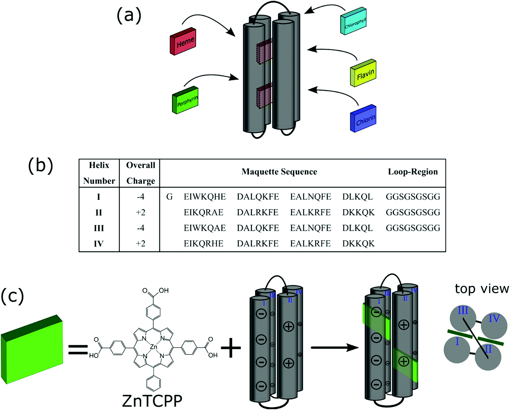 | ||
| Fig. 1 (a) Schematic of a maquette ligating various cofactors. (b) Amino acid sequence of maquette used within this study shown from N- to C-terminus, with helices numbered and the net-overall charges accompanying each helix. (c) Ligation of ZnTCPP with maquette to form an ensemble showing the charged helices. | ||
The incorporation of porphyrins into maquettes offers a unique possibility for photo-induced electron transfer and catalytic properties. It has been demonstrated that not only is a maquette-bound porphyrin more efficiently photo-oxidised than a free porphyrin but also that light-induced electron transfer between the porphyrin complex and an acceptor is faster and higher yielding.15,17 Furthermore, by controlling the amino acids and associated charges on the maquette surface, electrostatic interactions with conductive surfaces, and associated electron transfer can be achieved, providing a unique platform on which to build and study a light harvesting reaction centre replica.5,18
It is known that lysine residues of peptides can bind to titanium dioxide (TiO2) via electrostatic interactions, capable of orienting a peptide on the surface.19,20 In this study, a maquette sequence was designed to have appropriate amino acid charges on the maquette surface, in order to interact with TiO2 (Fig. 1b). This presented an opportunity to construct a photoanode to effectively measure photoinduced charge injection into titania by well-established methods.21 Here, we demonstrate that a zinc metalloporphyrin strongly binds to the maquette via ligation, and the resulting ensemble can be immobilised onto a TiO2 electrode. We show that the bound porphyrin maquette ensemble efficiently injects electrons from the photoexcited state of the ligated porphyrin into the conduction band of TiO2, with the maquette inhibiting electron recombination between the conduction band of TiO2 and a redox couple. This work establishes a process for the development of an artificial photosynthetic device utilizing charge separation to effect electron transfer processes.
Results and discussion
Preparation, purification and characterisation of ZnTCPP–GL-maquette
The zinc metalloporphyrin used for this study is 5,10,15-tri[(4-carboxyphenyl)-5-phenylporphyrinato zinc(II)] (ZnTCPP) (Fig. 1c), which was recently shown to ligate strongly in solution to a maquette.22 The GL-maquette used comprised 4-alpha helices of heptad repeats, including loop regions of glycine and serine that was based on our previously published maquette sequence with a variation in the amino acid sequences of helices II and IV.22 Helices I and III each have an overall charge of −4, with helices II and IV each containing an overall charge of +2 (Fig. 1b) that can promote electrostatic interactions with the oxide electrode. The design incorporates two offset histidine residues at the 7 and 112 positions that are each able to ligate to the metallic centre of a single porphyrin.As previously undertaken for porphyrins binding to maquettes,22 the binding of ZnTCPP to the GL-maquette was undertaken in CHES buffer (pH 8.5) ensuring solubility of both the maquette and the porphyrin and a binding titration was carried out (see Experimental procedures for details). This showed two distinct species, ligated ZnTCPP with a Soret peak at 433 nm (green spectrum, Fig. 2a), and unbound ZnTCPP at 422 nm (purple spectrum, Fig. 2a), becoming apparent after extending the concentration of ZnTCPP beyond the stoichiometric relationship of two ZnTCPPs to one maquette. The distinct red shift of the ZnTCPP absorption spectrum is typical of binding to maquettes, with the ligation of the central zinc to the histidine residue of the maquette influencing the transfer of charge to the porphyrin ring upon complexation.23
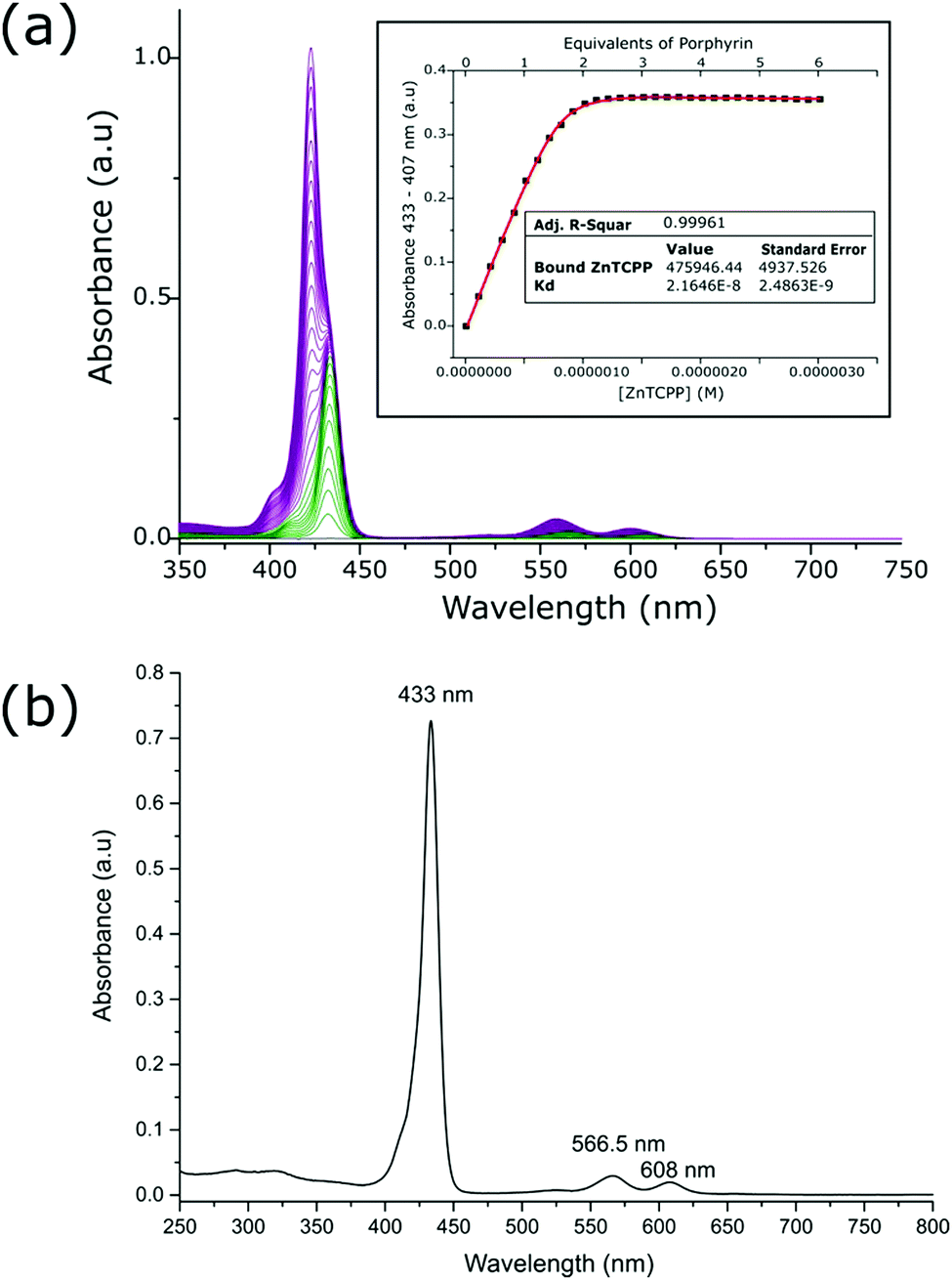 | ||
Fig. 2 (a) UV-vis absorption spectra of CHES buffer solution containing maquette with aliquot additions of ZnTCPP. ZnTCPP complexed with GL-maquette (green spectra with maxima at 433 nm) and monomeric ZnTCPP in solution (purple spectra with maxima at 422 nm) can be observed. A modelled fit of change in absorbance at bound porphyrin maxima compared to concentration of porphyrin present is given in the inset (see Experimental for details). (b) UV-vis spectrum of isolated and concentrated ZnTCPP–GL-maquette ensembles. Absorbance spectrum was obtained from a 100-fold dilution of the concentrated solution resulting from a mixture of 40![[thin space (1/6-em)]](https://www.rsc.org/images/entities/char_2009.gif) :100 maquette:ZnTCPP after 5 centrifugal runs in CHES buffer. :100 maquette:ZnTCPP after 5 centrifugal runs in CHES buffer. | ||
To determine the strength of binding, a measurement of the dissociation constant along with the extinction coefficient for the ligated ZnTCPP to the maquette was undertaken. The values were obtained by plotting the increase in absorbance at 433 nm versus the concentration of ZnTCPP, which was then modelled with a fitted curve (inset Fig. 2a). The extinction coefficient of the ligated ZnTCPP (476000 M−1 cm−1 at 433 nm) was comparable to that of ZnTCPP in DMSO (514600 M−1 cm−1 at 429.5 nm, Table S1, ESI†). Dissociation constant (Kd) values for ZnTCPP ligation were in the nano-molar range (22 × 10−9 M), which indicated tight binding, as has previously been shown with maquettes and porphyrins.22 In addition, the absorbance versus concentration curve (inset Fig. 2a) shows 2 equivalents of porphyrin present in the GL-maquette, indicating that each histidine ligated a single porphyrin molecule.
Further evidence for binding was provided by resonance Raman spectroscopy (Fig. S1, ESI†). Metalloporphyrin vibrational modes are known to show considerable sensitivity to the environment, whether in regard to planarity, metal oxidation state/spin or the presence of an auxiliary moiety.24–28 Resonance Raman results exhibit spectroscopic changes for ZnTCPP “core size” marker bands with the addition of the GL-maquette (Fig. S1, ESI†). Relative intensities for bands within 890–1610 cm−1 range increase when compared to the bands at 678 and 714 cm−1. Relative band intensities for ν4 and ν29 (1339–1353 cm−1) also change, with ν29 increasing by over 20%. There is a small red shift of this ν29 band from 1353 to 1350 cm−1. At the lower energy region, there is a small blue shift of the 1003 cm−1 band (ν15) to 1006 cm−1. These spectral changes support the binding of ZnTCPP to the maquette through a histidine residue. It should be noted that Feitelson and Spiro have shown that low frequency (150–250 cm−1) resonance Raman data can provide strong evidence for the Zn-histidine stretch, however, no significant bands could be observed in the low frequency regions.29
The solution stability of the ZnTCPP–GL-maquette ensemble was also confirmed (Fig. S2, ESI†) by measuring the absorbance spectrum of the ZnTCPP–GL-maquette over 2 h (Fig. S2a, ESI†), with the same measurement performed without maquette (Fig. S2b, ESI†). A stable spectrum under each condition was observed, apparent from the sharp Soret peak and pronounced Q bands, with no changes occurring over time indicating no release of the ZnTCPP from the maquette.
Isolation and purification of the ZnTCPP–GL-maquette ensembles was undertaken in order to ensure that there was no excess ZnTCPP when binding the ensemble to TiO2. This was performed by subjecting the ZnTCPP–GL-maquette ensemble solution containing an excess of ZnTCPP to multiple centrifuge runs in a protein concentrator tube with a molecular weight cut-off that was less than the molecular weight of the maquette, yet greater than the monomeric porphyrin. The resulting concentrated solution was analysed for purity (Fig. 2b), and for stoichiometric relationship (Fig. S3, ESI†), affording a maquette to porphyrin ratio of 1:1.95. As previously shown, this indicated that the two histidine residues present within the maquette were able to ligate strongly to the monomeric ZnTCPP. The resulting purified solution of ZnTCPP–GL-maquette ensembles was used for immobilisation onto TiO2.
Immobilisation of ZnTCPP–GL-maquette on TiO2
Immobilisation of the isolated ZnTCPP–GL-maquette ensembles in CHES buffer onto TiO2 was undertaken via electrostatic interaction. At the CHES buffer pH (8.5), the TiO2 surface is known to be negatively charged (pHIEP = 5.8–7.5),30 which allowed electrostatic interactions between the helices II and IV of the GL-maquette and TiO2. This dictated the binding geometry as indicated in Fig. 3a, with the ZnTCPP–GL-maquette ensemble lying on the TiO2 with one ligated porphyrin pointing towards the surface and one away from the surface. In order to determine the effect of the protein on the electron transfer from the ligated porphyrins, ZnTCPP, itself, was also immobilised onto TiO2 either from CHES buffer affording electrostatic surface interactions between the carboxylate groups formed in the CHES buffer (Fig. 3b) or directly from an organic solvent leading to covalent surface attachment (Fig. 3c). Covalent attachment to TiO2 is expected to occur using two binding modes by way of only one or two of the carboxylic groups.31 | ||
| Fig. 3 (a) Illustration of the immobilisation of maquette–ZnTCPP ensembles onto TiO2 from CHES buffer. (b) Illustration of the binding of the carboxylate salt of ZnTCPP to TiO2 from CHES buffer solution. (c) Illustration of the covalent binding of ZnTCPP to TiO2via sensitisation from THF. (d) UV-vis absorption spectra from 0.7 μm TiO2 of immobilised GL-maquette–ZnTCPP ensemble from CHES buffer (green line), bound carboxylate salt of ZnTCPP from CHES buffer (red line), and sensitised ZnTCPP from THF (black line). The inset is of modified 2.5 μm films of TiO2, showing the Q-band regions of the immobilised ZnTCPPs. (e) IPCE spectra from 2.5 μm TiO2 with immobilised GL-maquette–ZnTCPP ensemble from CHES buffer (green line), bound carboxylate salt of ZnTCPP from CHES buffer (red line), and sensitised ZnTCPP from THF (black line). | ||
The conditions for binding of the ZnTCPP–GL-maquette ensembles on TiO2 were established by both time and concentration dependent binding studies (Fig. S4 and S5, respectively, ESI†). These studies established that a maquette concentration of >20 μM and an exposure time of >24 h was effective for binding saturation of maquette to the surface of TiO2.
The absorbance spectrum of the ZnTCPP–GL-maquette ensembles on TiO2 was measured to determine whether the ZnTCPP remained ligated within the maquette once immobilised (green line, Fig. 3d). This was compared to the immobilisation of the carboxylate salt of ZnTCPP onto TiO2 from CHES buffer without maquette (red line, Fig. 3d). A distinct sharp Soret peak is observed at 432.5 nm for the bound ZnTCPP–GL-maquette ensembles, which is identical to the Soret peak for the ZnTCPP–GL-maquette ensembles in solution (Fig. 2b). Furthermore, the Q-band positions (Inset, Fig. 3d and Tables S1 and S2, ESI†) are also consistent in solution and on TiO2. In addition, the maquette–ligated ZnTCPP bands do not match those of the immobilised ZnTCPP salt (red line, Fig. 3d and Table S2, ESI†), which are similar to the covalently sensitised ZnTCPP (black line, Fig. 3d and Table S2, ESI†). It should be noted that the additional peak at 405.5 nm for the immobilised ZnTCPP salt has been previously reported to arise from the aggregation of porphyrins on oxide surfaces from aqueous solution.32,33
Incorporation of ZnTCPP–GL-maquette photoelectrodes into photovoltaic devices
With the immobilisation of ZnTCPP–GL-maquette ensembles onto a TiO2 electrode achieved, the electrodes could be used for light-driven charge separation within a photovoltaic device such as a dye sensitised solar cell (DSSC). In DSSCs, the energy levels of the photoactive material (dye) need to align with the energy levels of the semiconductor (in order to inject electrons from the photoexcited state) and that of a redox couple, which is required to regenerate the oxidised dye. Electron injection into the conduction band (CB) of the TiO2 semiconductor occurs from the lowest unoccupied molecular orbital (LUMO) of the dye and oxidised dye regeneration from its highest occupied molecular orbital (HOMO). The HOMO energy level can be determined electrochemically from the oxidation potential of the dye attached to the semiconductor while the LUMO energy level can be calculated (ELUMO = EHOMO − Eopt) from the optical band gap (Eopt), which is determined from the absorption onset at the highest wavelength in the porphyrin-modified TiO2 absorption spectrum (Fig. 3d).To evaluate the HOMO values, the oxidation potentials of ZnTCPP, ZnTCPP salt bound from CHES buffer, and the ZnTCPP–GL-maquette ensemble were determined using square wave voltammetry (Fig. S6, ESI†) and found to be 0.91, 0.91 and 0.89 V vs. NHE, respectively. The identical values for the ZnTCPP and ZnTCPP salt bound from CHES buffer indicated that the electronic state of ZnTCPP had not changed despite the difference in binding modes. The significantly lower oxidation current observed for the carboxylate ZnTCPP on TiO2 (red line, Fig. S6, ESI†) was due to the aggregative effects hindering electron injection into the electrode (as evident from the absorption spectrum (red line, Fig. 3d)). The lower value for the ZnTCPP–GL-maquette ensemble (∼20 mV) is likely due to a change in the electronic state of ZnTCPP as a result of ligation to the maquette through its central zinc. The lower current-response for ZnTCPP–GL-maquette compared to the sensitised ZnTCPP was attributed to the significantly lower concentration of ZnTCPP present in the maquette (2.30 ± 0.01 compared to 13.54 ± 0.52 nmol cm−2 μm−1, respectively, Table 1).
| Solar cellsa | V oc (mV) | J sc (mA cm−2) | FF | η (%) | Dye quantity (nmol cm−2 μm−1) | τ (ms) |
|---|---|---|---|---|---|---|
| a Made up of 2.5 μm TiO2 electrodes sensitised with ZnTCPP–GL-maquette, ZnTCPP salt and ZnTCPP using an acetonitrile-based iodide/triiodide redox mediator. The data shown is an average of that from 3 cells ± standard deviation. | ||||||
| ZnTCPP–GL-maquette | 652 ± 18 | 2.69 ± 0.10 | 0.73 ± 0.01 | 1.28 ± 0.11 | 2.20 ± 0.01 | 2.5 |
| ZnTCPP salt | 605 ± 5 | 4.15 ± 0.67 | 0.71 ± 0.02 | 1.77 ± 0.33 | 5.70 ± 1.20 | 0.8 |
| ZnTCPP | 560 ± 14 | 5.08 ± 0.57 | 0.72 ± 0.00 | 2.05 ± 0.27 | 13.54 ± 0.52 | 0.8 |
These gave calculated LUMO energy levels of −1.01, −1.00 and −0.93 V vs. NHE for sensitised ZnTCPP, ZnTCPP salt and the ZnTCPP–GL-maquette ensembles compared to the CB of TiO2 (−0.50 V vs. NHE),21 and indicated that it was possible for electrons to be injected into the CB as shown in the energy level diagram in Fig. S7 (ESI†). In addition, the HOMO values indicated that the dye could be regenerated from the oxidised dye by a redox couple such as I−/I3−, since the redox potential of the I−/I3− electrolyte within an organic solvent is 0.35 V vs. NHE and the required driving force for effective regeneration is approximately 0.5 eV.34,35
It is noteworthy that while the HOMO–LUMO levels for both the sensitised and ZnTCPP salt were identical, the energy levels for the maquette-bound ZnTCPP differed. This was in agreement with the differences observed in the absorbance spectra, with the electronic state of the maquette-bound ZnTCPP being influenced by ligation.36
The influence of the maquette on electron injection from protein-bound zinc porphyrins has been addressed previously. It has been demonstrated that direct photoinduced electron transfer into TiO2 from Zn protoporphyrins ligated to either cytochrome C or a maquette that are immobilised on TiO2 takes place on the nanosecond time scale,5 somewhat slower than for a porphyrin directly attached to TiO2 that is typically sub-picosecond.37
Sensitised thin film (2.5 μm) TiO2 electrodes were then used for assembly of DSSC constructs,21 whose photocurrent density (J) versus voltage (V) curves are given in Fig. S8 (ESI†) and the full photovoltaic data derived from these curves in Table 1. The value of the short circuit current density (Jsc) is a direct measure of the overall light absorption of the dye, efficiency of electron injection of the photoexcited dye and charge collection by the photoanode. If electrons within the photoanode recombine with the redox mediator (I3−), this is reflected in a lowering of the open circuit voltage (Voc). The fill factor (FF) is a measure of the quality of the photovoltaic device and indicative of the total resistances within the device. The overall DSSC conversion efficiency (η) is a combination of these photovoltaic characteristics (η = Voc × Jsc × FF) and so depends on the balance between the kinetics of electron injection, regeneration, and recombination reactions.38 Within porphyrin-based devices, the dye structure and arrangement of dyes on the semiconductor surface both contribute to a lower Voc than obtained in ruthenium dye-based devices.39,40
It was evident from the devices utilising the immobilised maquettes containing ligated ZnTCPP that the immobilised ensembles could indeed accomplish light driven electron injection into the CB of TiO2 as demonstrated by the mA response in Jsc (2.69 ± 0.10 mA, Table 1). As was expected, the two control cells had higher currents, with the sensitised ZnTCPP having the highest measured Jsc and the ZnTCPP salt being slightly lower (5.08 ± 0.57 and 4.15 ± 0.67 mA, respectively). However, the quantity of photoactive material (ZnTCPP) present is 6-fold less for devices utilising the ZnTCPP–GL-maquette ensemble compared to those with only ZnTCPP and 2.5-fold less than the ZnTCPP salt devices (Table 1). With Jsc being directly related to the quantity of photoactive material on the semiconducting surface injecting electrons,21 these results clearly indicate that when ZnTCPP is ligated to the maquette, the efficiency of the electron injection is higher; there was a higher amount of current than expected coming from the ligated ZnTCPP molecules than the sensitised porphyrins.
The Incident Photon to Current Efficiency (IPCE) was measured to compare the differences in current responses with the absorbance profiles on the TiO2 for the devices (Fig. 3e). The IPCE combines contributions from the light-harvesting efficiency, the efficiency of electron injection from the photoexcited dye into the TiO2 conduction band, and the efficiency of charge collection at the electrodes. In thin (2.5 μm) porphyrin-sensitised TiO2 DSSCs, the mean diffusion length of electrons is larger than the electron lifetime and, therefore, the charge collection efficiency is assumed to be close to 100%.41 It is notable that the total currents extracted from the IPCE curves are comparable to those from the I–V measurements, albeit somewhat smaller due to the lower light intensity used for IPCE measurement; the relative magnitude of the current densities is almost identical. As expected all the IPCE profiles tend to follow the absorbance curves, although it appears that the peak due to the aggregation of the ZnTCPP salt (405.5 nm, red line, Fig. 3d) does not contribute to the photocurrent as might be expected.42 Since it has been previously reported that electron injection in porphyrin-based DSSCs mostly occurs from the lowest photoexcited state,43 and there is little difference between the IPCEs of these three devices, it can be assumed that injection from the maquette–ligated porphyrin is also mostly from the lowest photoexcited state.
Differences in device performances were further evident in the Voc (Table 1), where devices with the immobilised ensembles had the highest Voc compared to the other two devices. Such an increase in Voc is typically ascribed to a reduction in electron recombination from the CB of TiO2 to the redox mediator.39,40 However, the differences in Voc and Jsc between devices could also be accounted for by a shift in the CB edge of TiO2 to higher energy as a result of a pH increase.44 As discussed above for the binding of the maquette, the surface of TiO2 is typically acidic (pHIEP = 5.8–7.5),30 which would be affected by exposure to the CHES buffer (pH 8.5). Nevertheless, as the ZnTCPP salt and ZnTCPP–GL-maquette ensemble-based devices were both prepared using CHES buffer and show different Vocs (Table 1), the increased Voc of the ensemble devices cannot be solely due to the effect of pH.
Further characterisation through electrochemical impedance spectroscopy (EIS) gives insight into the resistances and capacitance at the various interfaces within the devices.45,46 The EIS was carried out on each device at Voc under 1 sun and the resulting Nyquist and Bode plots are shown in Fig. 4a and b, respectively. To interpret the EIS data, an equivalent circuit model (Fig. 4c) was used to account for the resistances and capacitances associated with each observed interface, and the resulting data is given in Table S3 (ESI†). The series resistance (Rs) relates to the resistance of the FTO substrates and contact resistances of the circuit, with the series resistance observed to be highly similar between all measured devices (Table S3, ESI†). The Nyquist plots (Fig. 4a) displayed two significant semicircles for the different electron transfer processes occurring at the various electrochemical interfaces within the devices.46 The resistances and capacitances were assigned to each interface observed, where R1 and C1 corresponds to higher frequencies (smaller semicircle at lower Z′ value), and R2 and C2 corresponding to lower frequencies observed (larger semicircle at higher Z′ value). Typically, diffusion limitations of the redox electrolyte are observed within the lower frequency range. However, due to the short distance between electrodes (25 μm), no diffusion impedance can be observed within the investigated frequency range for all devices measured.
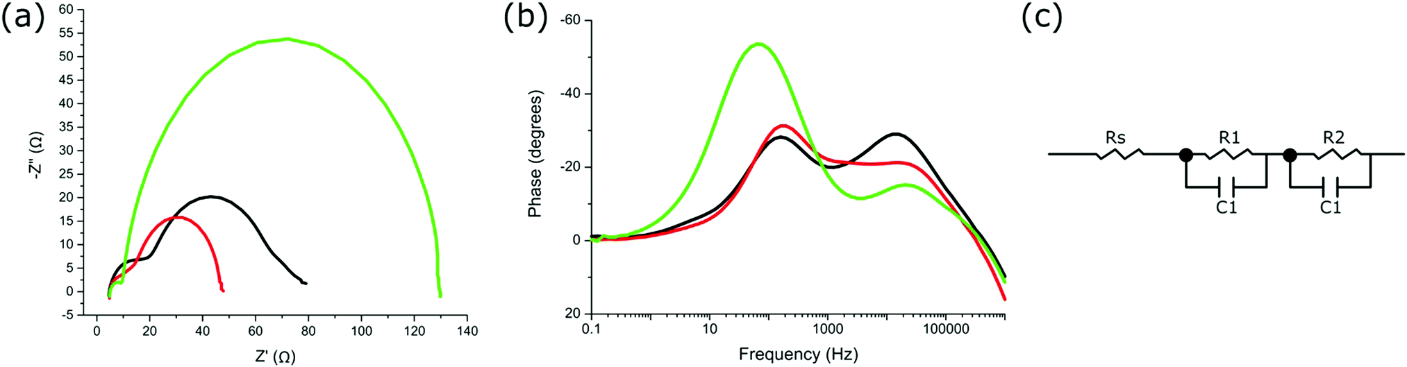 | ||
| Fig. 4 (a) Nyquist plot of devices utilizing sensitised ZnTCPP (black line), ZnTCPP salt (red line), and immobilised ZnTCPP–GL-maquette ensemble (green line). (b) Bode plot of devices utilizing sensitised ZnTCPP (black line), ZnTCPP salt (red line), and immobilised ZnTCPP–GL-maquette ensemble (green line). (c) The equivalent circuit diagram used for fitting the EIS data. | ||
The predominant electron transfer process observed (R2 and C2, larger semicircle) is associated with the reverse electron transfer (recombination) from the conduction band of TiO2 to the redox electrolyte (I3−) (Fig. 4a).45 The smaller semicircle at the higher frequency range (R1 and C1) is a combination of the charge transfer processes between TiO2 and the FTO glass substrate, between nanoparticles of TiO2, and also between the electrolyte and catalytic platinum layer on the counter electrode.45 Since the devices were prepared in an identical manner, the electron transfer between TiO2 and FTO or at the counter electrode was not expected to differ between devices. Therefore, any differences in R1 should have come from the transport processes between TiO2 nanoparticles. R1 is shown to be highest for devices with sensitised ZnTCPP, with the lowest resistance for devices containing ZnTCPP–GL-maquette ensembles (Table S3, ESI†). This lower resistance suggests more efficient electron transport at the boundaries of the TiO2 nanoparticles.45R2 is the resistance associated with the predominant semicircle (lower frequency range), relating to recombination processes at this TiO2–dye–electrolyte interface. Both R2 and C2 are notably larger in devices employing ZnTCPP–GL-maquette ensembles (Table S3, ESI†). The larger capacitance corresponds to a higher density of accessible electronic states at the interface.47 The higher resistance indicates that the electron is less likely to recombine from the conduction band of TiO2 back to the redox electrolyte.
One further characteristic obtained from EIS analysis is the electron lifetime associated with the electron recombination from the CB of TiO2 back to the redox mediator.45 Electron lifetime is the time of electron survival in the conduction band of TiO2 before recombination with I3−, and is determined by the rate of back reaction to the electrolyte.48 Electron lifetimes were calculated from the Bode phase shift versus frequency plots as τ ≈ 1/ωmin = 1/2πfmin where fmin is the frequency at which the phase shift is minimum (Fig. 4b).46 The lifetimes for devices with ZnTCPP–GL-maquette ensembles, ZnTCPP salt, and sensitised ZnTCPP were 2.5, 0.8, and 0.8 ms, respectively (Table 1). This result supports the observed Voc differences shown previously (Table 1), in that a higher electron lifetime is indicative of reduced recombination from the CB of TiO2 to the electrolyte after photoinduced electron injection and a resulting higher Voc.
It is worthy of note that these results represent a significant advance on previous photoelectrochemical devices fabricated using proteins. The best results to date for natural photosystems immobilised on semiconductor substrates such as TiO2, zinc oxide or hematite incorporated into a photoelectrochemical cell have yielded photocurrents of 100s of μA cm−2 and voltages of only up to 0.5 V.3 Shah et al. have obtained a Jsc of 4.15 mA cm−2 for a biophotoelectrode comprised of photosystem-I on TiO2 but this was in a biased half photoelectrochemical cell configuration using a sacrificial electron donor.49 In addition, these protein-based devices typically degrade over a matter of hours, whereas the maquette photoanodes show no apparent degradation over this time and indeed similar systems have been reported to be stable for weeks.5
Conclusions
In this work, we have demonstrated that a stable complex of an artificial protein and a light harvesting porphyrin can be immobilised onto a TiO2 electrode and that the bound porphyrin protein maquette assembly efficiently injects electrons from the photoexcited state of the ligated porphyrin into the conduction band of TiO2. The beneficial effect of the maquette is demonstrated by the fact that, in the presence of the protein, significantly less porphyrin is required to achieve a similar level of photocurrent as is obtained when the same porphyrin is covalently bound to the TiO2 semiconductor. In addition, there is a substantial increase in photovoltage as a result of the shielding of the TiO2 surface by the protein leading to reduced electron recombination with the redox mediator. While this study has led to the best protein-based photovoltaic device reported, the potential of the porphyrin protein assembly lies in its ability to be coupled to other chemical processes such as occur in photosynthesis. With the design of both the maquette and porphyrin able to be altered to allow the coupling of the electron generation to adjacent catalysts,13 this maquette-porphyrin ensemble-based photoanode represents one of the most promising advances for the development of a truly artificial photosynthetic reaction centre.Experimental
Porphyrin-maquette binding titration
The binding titration of porphyrin to maquette was done by adding small aliquots of 1 μl from stock porphyrin solution (200 μM porphyrin in DMSO) to 2 ml of 0.5 μM maquette solution in CHES buffer (20 mM CHES and 150 mM KCl, adjusted to pH = 8.5 with KOH), increasing porphyrin concentration by 0.1 μM per aliquot. Absorbance spectra were measured after mixing each additional aliquot for 1 min (Fig. 2a). By plotting the change in absorbance at 433 nm (absorbance maxima of bound porphyrin) vs. the concentration of porphyrin added, the calculated extinction coefficient, dissociation constant (Kd), and stoichiometric relationship of a modelled fit (Fig. 2a) can be obtained using eqn (1).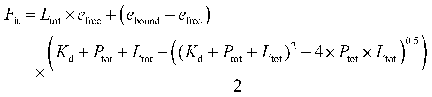 | (1) |
e free = extinction coefficient of free porphyrin§
e bound = extinction coefficient of bound porphyrin§
P tot = concentration of maquette¶
K d = dissociation constant§
Porphyrin-maquette ensemble in solution
To obtain a pure and concentrated solution of ZnTCPP–GL-maquette ensembles, 40 μM maquette was mixed with 100 μM ZnTCPP in 1 ml of CHES Buffer for 1 h, followed by centrifugation in a 3 kDa MWCO (molecular weight cut off) protein concentrator tube (GE Life Sciences). The solution was centrifuged 5 times, with CHES buffer added between spins to a final volume of 1 ml. The UV-vis absorbance spectrum of a 100 fold diluted maquette–ZnTCPP ensemble solution was measured to analyse concentration and purity (Fig. 2b).The concentration was calculated to be 156 μM of bound ZnTCPP (based on ε = 476000 M−1 cm−1 at 433 nm). The concentration of maquette was calculated to be 80 μM, based on the relative change in absorbance at 280 nm, corresponding to the tryptophan absorbance maxima in the maquette (with an extinction coefficient of 11200 M−1 cm−1), compared to the change in absorbance at 433 nm with the increase in ZnTCPP concentration (Fig. S3, ESI†). The calculated maquette to ZnTCPP ratio was 1:1.95.
Binding of porphyrins and ensembles onto TiO2
Sensitisation of ZnTCPP directly to TiO2 was accomplished by submerging a TiO2 electrode into 200 μM ZnTCPP solution in THF for 3 h. Samples were then rinsed in acetonitrile and dried with N2-gas stream before measurements and device fabrication.Binding of ZnTCPP to TiO2 from a CHES buffer was accomplished by drop-casting 100 μl of 100 μM ZnTCPP solution in CHES buffer onto TiO2, with the electrode sealed in a Petri dish (to reduce any evaporation), and left for 48 h in the dark at 4 °C. The treated electrode was then rinsed in CHES buffer and dried with N2-gas stream before measurements and device fabrication.
The isolated ZnTCPP–GL-maquette ensemble solution (undiluted) with known concentrations of bound ZnTCPP and maquette (Fig. S3, ESI†) was diluted to give 100 μM ligated ZnTCPP (and hence 51 μM maquette) in CHES buffer. The resulting solution was drop-casted onto TiO2, with the electrode sealed in a Petri dish, left for 48 h in the dark at 4 °C. The treated electrodes were then rinsed in CHES buffer and dried with N2-gas stream before measurements and device fabrication.
Device assembly
TiO2 films were prepared on FTO substrates (Hartford TEC8, 2.3 mm, Rs < 8 Ω □−1) by screen-printing 4 × 4 mm areas of one 2.5 μm transparent layer (DSL 18 NR-T paste, Dyesol), or one 2-fold terpineol diluted (mass to mass) layer (0.7 μm) using a 96 T screen. All film thicknesses were measured using a Dektak 150 Profilometer. The TiO2 films were sintered stepwise using a programmable hot plate with a maximum temperature of 500 °C. Each film was reheated to 450 °C for 20 min and cooled to 110 °C for 30 min before any treatment.Counter electrodes were prepared by platinising TEC8 FTO with an ethanolic 10 mM H2PtCl6 solution at 400 °C for 20 min.
Sandwich-type DSSCs were assembled using a 25 μm Hymilan sealant. An electrolyte solution composed of 0.6 M 1-butyl-3-methylimidazolium iodide (BMII), 0.5 M 4-tert-butylpyridine, 0.1 M LiI, and 0.03 M I2 in a solvent mixture of 85:15 acetonitrile/valeronitrile was injected between the electrodes through a hole in the counter electrode, which was subsequently sealed. Devices were measured under 1 sun irradiation.
Conflicts of interest
There are no conflicts to declare.Acknowledgements
This work was supported by Australian Research Council (ARC) Discovery Project DP 150104532 and the ARC Centre of Excellence Scheme (Project Number CE 140100012). The authors thank the Australian National Fabrication Facility for facilities. The support of the New Zealand MacDiarmid Institute for Advanced Materials and Nanotechnology is gratefully acknowledged. This research was carried out as part of the Photosynthetic Antenna Research Center (PARC), an Energy Frontier Research Center funded by the U.S. Department of Energy, Office of Science, Office of Basic Energy Sciences, under Award DESC0001035 supporting G. K., P. L. D. and C. C. M. in maquette construction and characterisation.Notes and references
- J. Barber, Chem. Soc. Rev., 2009, 38, 185–196 RSC.
- C. Koroneos, A. Dompres, G. Roumbus and N. Moussiopoulos, Int. J. Hydrogen Energy, 2004, 29, 1443–1450 CrossRef CAS.
- V. M. Friebe and R. N. Frese, Curr. Opin. Electrochem., 2017, 5, 126–134 CrossRef CAS.
- H. C. Fry, Y. Liu, N. M. Dimitrijevic and T. Rajh, Nat. Commun., 2014, 5, 4606 CrossRef CAS PubMed.
- E. Topoglidis, B. Discher, C. C. Moser, P. L. Dutton and J. Durrant, ChemBioChem, 2003, 4, 1332–1339 CrossRef CAS PubMed.
- B. M. Discher, D. Noy, J. Strzalka, S. Ye, C. C. Moser, J. D. Lear, J. K. Blasie and P. L. Dutton, Biochemistry, 2005, 44, 12329–12343 CrossRef CAS PubMed.
- D. Robertson, R. Farid, C. C. Moser, J. Urnauer, S. Mulholland, R. Pidikiti, J. Lear, J. Wand, W. Degrado and P. L. Dutton, Nature, 1994, 368, 425–432 CrossRef CAS PubMed.
- J. Bryson, S. Betz, H. Lu, D. Suich, H. Zhou, K. O'Neil and W. Degrado, Science, 1995, 270, 935–941 CrossRef CAS PubMed.
- P. L. Dutton and C. C. Moser, Faraday Discuss., 2011, 148, 443–448 RSC.
- B. Gibney, F. Rabanal, J. Skalicky, J. Wand and P. L. Dutton, J. Am. Chem. Soc., 1997, 119, 2323–2324 CrossRef CAS.
- R. E. Sharp, C. C. Moser, F. Rabanal and P. L. Dutton, Proc. Natl. Acad. Sci. U. S. A., 1998, 95, 10465–10470 CrossRef CAS.
- S. Mulholland, B. Gibney, F. Rabanal and P. L. Dutton, Biochemistry, 1999, 38, 10442–10448 CrossRef CAS PubMed.
- I. Willner, V. Heleg-Shabtai, E. Katz, H. K. Rau and W. Haehnel, J. Am. Chem. Soc., 1999, 121, 6455–6468 CrossRef CAS.
- L. Eggink and J. K. Hoober, J. Biol. Chem., 2000, 275, 9087–9090 CrossRef CAS PubMed.
- A. R. Razeghifard and T. Wydrzynski, Biochemistry, 2003, 42, 1024–1030 CrossRef PubMed.
- S. Huang, R. Koder, M. Lewis, J. Wand and P. L. Dutton, Proc. Natl. Acad. Sci. U. S. A., 2004, 101, 5536–5541 CrossRef CAS PubMed.
- V. Tipmanee, H. Oberhofer, M. Park, K. S. Kim and J. Blumberger, J. Am. Chem. Soc., 2010, 132, 17032–17040 CrossRef CAS PubMed.
- X. Chen, B. Discher, D. Pilloud, B. Gibney, C. C. Moser and P. L. Dutton, J. Phys. Chem., 2002, 103, 617–624 CrossRef.
- A. D. Roddick-Lanzilotta and A. J. McQuillan, J. Colloid Interface Sci., 1999, 217, 194–202 CrossRef CAS PubMed.
- M. Kato, T. Cardona, A. W. Rutherford and E. Reisner, J. Am. Chem. Soc., 2013, 135, 10610–10613 CrossRef CAS PubMed.
- A. Hagfeldt, G. Boschloo, L. Sun, L. Kloo and H. Pettersson, Chem. Rev., 2010, 110, 6595–6663 CrossRef CAS PubMed.
- G. Kodali, J. A. Mancini, L. A. Solomon, T. V. Episova, N. Roach, C. J. Hobbs, P. Wagner, O. A. Mass, K. Aravindu, J. E. Barnsley, K. C. Gordon, D. L. Officer, P. L. Dutton and C. C. Moser, Chem. Sci., 2017, 8, 316–324 RSC.
- M. Nappa and J. S. Valentine, J. Am. Chem. Soc., 1978, 100, 5075–5080 CrossRef CAS.
- J. A. Shelnutt, K. Alston, J. Y. Ho, N. T. Yu, T. Yamamoto and J. M. Rifkind, Biochemistry, 1986, 25, 620–627 CrossRef CAS PubMed.
- J. A. Shelnutt, C. J. Medforth, M. D. Berber, K. M. Barkigia and K. M. Smith, J. Am. Chem. Soc., 1991, 113, 4077–4087 CrossRef CAS.
- T. G. Spiro, J. D. Stong and P. Stein, J. Am. Chem. Soc., 1979, 101, 2648–2655 CrossRef CAS.
- T. G. Spiro and T. C. Strekas, J. Am. Chem. Soc., 1974, 96, 338–345 CrossRef CAS.
- Y.-H. Zhang, W. Zhao, P. Jiang, L.-J. Zhang, T. Zhang and J. Wang, Spectrochim. Acta, Part A, 2010, 75, 880–890 CrossRef PubMed.
- J. Feitelson and T. G. Spiro, Inorg. Chem., 1986, 25, 861–865 CrossRef CAS.
- R. Beranek, Adv. Phys. Chem., 2011, 1–20 Search PubMed.
- L. Zhang and J. M. Cole, ACS Appl. Mater. Interfaces, 2015, 7, 3427–3455 CrossRef CAS PubMed.
- R. Azumi, M. Matsumoto, Y. Kawabata, S. Kuroda, M. Sugi, L. G. King and M. J. Crossley, J. Phys. Chem., 1993, 97, 12862–12869 CrossRef CAS.
- G. A. Schick, I. C. Schreiman, R. W. Wagner, J. S. Lindsey and D. F. Bocian, J. Am. Chem. Soc., 1989, 111, 1344–1350 CrossRef CAS.
- G. Boschloo and A. Hagfeldt, Acc. Chem. Res., 2009, 42, 1819–1826 CrossRef CAS PubMed.
- I. Montanari, J. Nelson and J. R. Durrant, J. Phys. Chem. B, 2002, 106, 12203–12210 CrossRef CAS.
- C.-l. Lin, M.-Y. Fang and S.-H. Cheng, J. Electroanal. Chem., 2002, 531, 155–162 CrossRef CAS.
- A. S. Hart, C. B. Kc, H. B. Gobeze, L. R. Sequeira and F. D’Souza, ACS Appl. Mater. Interfaces, 2013, 5, 5314–5323 CrossRef CAS PubMed.
- S. A. Haque, E. Palomares, B. M. Cho, A. N. M. Green, N. Hirata, D. R. Klug and J. R. Durrant, J. Am. Chem. Soc., 2005, 127, 3456–3462 CrossRef CAS PubMed.
- M. J. Griffith, M. James, G. Triani, P. Wagner, G. G. Wallace and D. L. Officer, Langmuir, 2011, 27, 12944–12950 CrossRef CAS PubMed.
- M. J. Griffith and A. J. Mozer, in Solar Cells, ed. L. A. Kosyachenko, INTECH Open Access Publisher, Rijeka, 2011, ch. 16, vol. 2 Search PubMed.
- A. J. Mozer, P. Wagner, D. L. Officer, G. G. Wallace, W. M. Campbell, M. Miyashita, K. Sunahara and S. Mori, Chem. Commun., 2008, 4741–4743 RSC.
- J. L. McHale, J. Phys. Chem. Lett., 2012, 3, 587–597 CrossRef CAS PubMed.
- K. Wagner, M. J. Griffith, M. James, A. J. Mozer, P. Wagner, G. Triani, D. L. Officer and G. G. Wallace, J. Phys. Chem. C, 2011, 115, 317–326 CrossRef CAS.
- G. Rothenberger, D. Fitzmaurice and M. Graetzel, J. Phys. Chem., 1992, 96, 5983–5986 CrossRef CAS.
- T. Hoshikawa, M. Yamanda, R. Kikuchi and K. Eguchi, J. Electrochem. Soc., 2005, 152, E68–E73 CrossRef CAS.
- R. Kern, R. Sastrawan, J. Ferber, R. Stangl and J. Luther, Electrochim. Acta, 2002, 47, 4213–4225 CrossRef CAS.
- F. Fabregat-Santiago, G. Garcia-Belmonte, I. Mora-Sero and J. Bisquert, Phys. Chem. Chem. Phys., 2011, 13, 9083–9118 RSC.
- J. Bisquert, F. Fabregat-Santiago, I. Mora-Seró, G. Garcia-Belmonte and S. Giménez, J. Phys. Chem. C, 2009, 113, 17278–17290 CrossRef CAS.
- V. B. Shah, W. R. Henson, T. S. Chadha, G. Lakin, H. Liu, R. E. Blankenship and P. Biswas, Langmuir, 2015, 31, 1675–1682 CrossRef CAS PubMed.
Footnotes |
| † Electronic supplementary information (ESI) available: Materials, instrumentation and characterisation, supplementary methods, six supplementary figures and three supplementary tables. See DOI: 10.1039/d0ma00427h |
| ‡ Denotes data parameter. |
| § Denotes free parameter for data fitting. |
| ¶ Denotes fixed parameter. |
| This journal is © The Royal Society of Chemistry 2020 |