 Open Access Article
Creative Commons Attribution 3.0 Unported Licence
New insights into size-controlled reproducible synthesis of anisotropic Fe3O4 nanoparticles: the importance of the reaction environment†
Gurvinder
Singh
 *a,
Vladimir S.
Myasnichenko
b and
Wilhelm R.
Glomm
c
aSchool of Biomedical Engineering, University of Sydney, Sydney, NSW 2008, Australia. E-mail: gurvinder.singh@sydney.edu.au
bTver State University, Sadovyi per., 35, 170002, Tver, Russia
cDepartment of Biotechnology and Nanomedicine, SINTEF Industry, 7465, Norway
First published on 22nd July 2020
Abstract
Synthesis of size-controlled anisotropic magnetite (Fe3O4) nanoparticles allows designing next-generation magnetic nanosystems with predetermined magnetic properties suited for particular applications in the biomedical, information, and environment fields. In this work, we report a reproducible and economical approach for fabricating anisotropic Fe3O4 nanoparticles via the thermal decomposition method. Controlling the reaction environment, i.e. the degassing pressure, is essential to obtain the reproducible synthesis of anisotropic Fe3O4 nanoparticles along with monodispersity in the size and shape. At low degassing pressure, Fe3O4 nanocubes are formed, and an increase in degassing pressure leads to the formation of Fe3O4 octahedral nanoparticles. To achieve good reproducibility (with respect to size and shape) between different batches, our finding reveals the importance of maintaing the same degassing pressure. The size of the anisotropic Fe3O4 nanoparticles can be varied by changing the heating rate and the solvent amount. The amount of solvent has also an influence on the shape of the nanoparticles, and Fe3O4 nanoparticles of flower morphology are obtained at a high solvent amount. The work also provides new conceptual fundamental insights into understanding the growth mechanism of anisotropic Fe3O4 nanoparticles and thus advancing the field of materials chemistry for rationally designing anisotropic nanoparticles with tunable magnetic properties.
The reproducible and economical synthesis of anisotropic magnetite (Fe3O4) nanoparticles (NPs) with narrow size distribution continues to be a topic of considerable interest owing to their unique magnetic properties1 and numerous potential applications related to the biomedical,2,3 catalysis,4,5 environment,6 light emitting device,7 and sensing8 fields. Anisotropic Fe3O4 NPs offer two main advantages. First, the magnetic properties of Fe3O4 NPs depend on the shape as well as their size and size distribution.9–11 This allows the design of advanced magnetic NPs with predetermined properties suited for specific applications. Recent studies demonstrated that anisotropic Fe3O4 NPs offer higher magnetic hyperthermia efficiency,12,13 enhanced contrast in magnetic resonance imaging,11,14,15 better targeting efficiency due to a large surface to volume ratio,16 and longer blood circulation time compared to spherical Fe3O4 NPs.17 Second, the self-assembly of anisotropic Fe3O4 NPs depends on the shape, thus resulting in a rich variety of self-assembled superstructures of distinct morphologies.18,19 Such magnetic superstructures exhibit collective magnetic and magnetically enhanced mechanical properties which can be tailored by the shape of the NPs as well as the morphology of self-assembled superstructures.20
In the last two decades, various approaches based on the microemulsion,21 co-precipitation,22 hydrothermal,23 and thermal decomposition10,24–27 methods have been researched for the synthesis of anisotropic Fe3O4 NPs. Among these, thermal decomposition of iron oleate in the presence of oleic acid and/or sodium oleate and octadecene has been used to synthesize Fe3O4 NPs in different shapes (cubic, octapods, octahedra, plates, and rods),11,18,28 resulting in good control over the shape and size (3–25 nm). However, this approach does not lead to fabrication of anisotropic Fe3O4 NPs with phase purity, which can negatively influence the crystallinity/structure of the NPs and, thus, their magnetic properties. An alternative approach is based on the thermal decomposition of iron(III) acetylacetonate (Fe(acac)3) in the presence of oleic acid (OA) as a surfactant and dibenzyl ether (BE) as a solvent.29 This reaction yields considerably larger anisotropic Fe3O4 NPs (size >70 nm) because of the faster reaction compared to the one based on iron oleate. The rate of reaction can be slowed down by using either other ligands such as decanoic acid and 4-biphenylcarboxylic acid instead of oleic acid or a mixture of solvents (BE + squalene or BE + octadecene + tetradecane).10,16,29 The purpose of the use of a solvent mixture is that BE decomposes to benzyl benzoate and benzaldehyde at high temperature, causing a temperature fluctuation of the reaction, which results in poor reproducibility between different batches. Despite the synthesis of Fe3O4 nanocubes in a size range of 15–100 nm, these synthetic approaches offer less flexibility in shape control and require the use of additional expensive solvents and ligands. It is known that the rate of reaction kinetics depends on several factors, including the activity of the precursor, the ligand type, the interaction between the ligand and the precursor, temperature, time, the heating rate and the reaction environment.24,30 However, the role of the reaction environment (i.e. degassing pressure) and heating rate in the control of the reaction kinetics and reproducibility in size-and shape-controlled synthesis of anisotropic Fe3O4 NPs has not been investigated.
Here, we demonstrate a reproducible one-pot synthesis of pure anisotropic Fe3O4 NPs with control over the size and size distribution. The approach involves the decomposition of Fe(acac)3 only in the presence of BE solvent and OA. Our results show that controlling the heating rate of the reaction and the residual oxygen content in the reaction is crucial to regulate the reduction kinetics, and thus to reproducibly obtain anisotropic Fe3O4 NPs in different sizes with a narrow size distribution despite the temperature fluctuation (±5 °C) during the reaction. We also further elucidate the understanding of the reaction mechanism by controlled experiments. The proposed approach is very robust (i.e. high reproducibility between different batches) and economical because it does not rely on the use of a combination of expensive solvents (octadecene, squalene, tetradecane, and sodium oleate) and additional ligands. Overall, this is the first study reporting variation in the shape and size of Fe3O4 NPs without any need for adding another solvent and ligands. The present work contributes to the fundamental mechanistic understanding of colloidal synthesis and will facilitate the design of magnetite NPs with predetermined magnetic properties tailored to specific applications.
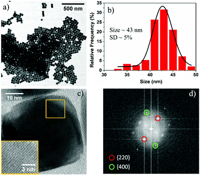
In a typical synthesis, Fe(acac)3 (0.706 g, 2 mmol) was added to a reaction mixture of 20 mL BE and 1.26 mL OA. The resultant solution was degassed (residual pressure ∼ 0.19 mbar) at room temperature for 90 min and then heated to 290 °C at a rate of 8 °C min−1 under an argon (Ar) atmosphere and vigorous magnetic stirring. After maintaining the reaction at this temperature for 30 min, the solution was cooled down to room temperature. The reaction product was precipitated with a mixture of toluene and isopropanol and magnetically separated. Bright field (BF) scanning transmission electron microscopy (STEM) images reveal the cubic morphology of Fe3O4 NPs, and the average size of the nanocubes is determined to be ∼43 nm with a standard deviation (SD) of ∼5% (Fig. 1a and b). Note that due to the degassing of the reaction mixture, we observed lower fluctuation in the reaction temperature (290° ± 5 °C) during the reaction, which is significantly lower than previously reported literature.16 It should further be noted that similar size Fe3O4 NPs of cubic morphology can be reproducibly synthesized between different batches at a fixed degassing pressure.
High resolution transmission electron microscopy (HRTEM) images reveal the single crystalline nature of the cubic NPs with rounded corners (Fig. 1c). The FFT pattern of the single crystalline NPs is indexed with the help of CrystBox software,31 and the diffraction spots (220) and (400) correspond to interplanar spacing values of 2.95 Å and 2.09 Å, respectively (Fig. 1d). The interplanar lattice spacing was also determined from the image produced from the inverse FFT by choosing the {220} and {400} reflections and found to be approximately close to the theoretical values (2.95 Å and 2.09 Å) for the Fe3O4 system (see Fig. S1, ESI†). These results suggest that nanocubes are formed because of the rapid growth along the 〈111〉 direction, and the surface of the final product is formed from six Fe3O4{100} facets with eight rounded corner Fe3O4{111} facets. The crystal structure of these NPs can be assigned to a FCC (face centered cubic) Fe3O4 structure based on the interplanar spacings and the ratio between different planes, including the angles between the planes. To confirm the crystal structure of the Fe3O4 NPs, we used X-ray diffraction. The XRD pattern shows the presence of a pure Fe3O4 phase in the as-synthesized NPs, which is in agreement with JCPDS card no. 019-0629 (see Fig. S2, ESI†).
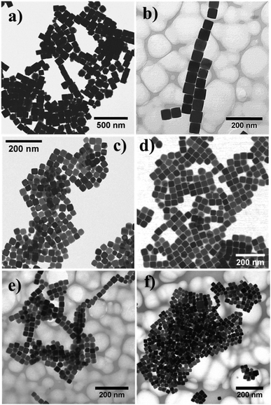
To tune the size of the Fe3O4 nanocubes, the heating rate was varied under otherwise identical experimental conditions. At low heating rates (1 °C min−1 and 2 °C min−1), two distinct size populations of the Fe3O4 nanocubes were observed around ∼70 nm and ∼240 nm (see Fig. S3 and S4, ESI†). The reaction at a heating rate of 3 °C min−1 led to the formation of Fe3O4 nanocubes of size ∼85 nm (Fig. 2a). On further increasing the heating rate from 5 °C min−1 to 20 °C min−1, the average size of the NPs decreases from 58 nm (SD ∼ 5%) to 26 nm (SD ∼ 9%), as shown in Fig. 2b–f. The formation of different size Fe3O4 nanocubes via thermal decomposition of Fe(acac)3 at a high temperature can be explained by the LaMer model.24,32 According to this model, when the concentration of monomers goes above the supersaturation limit, nucleation occurs very quickly to bring down the concentration of monomers below the supersaturation limit, thus inhibiting multiple nucleation events. Later, the growth of pre-formed nuclei proceeds by consuming monomers via diffusion and adsorption. To obtain NPs in different sizes with a narrow size distribution, it is thus necessary to separate the nucleation and growth processes. When the heating rate is very low (<3 °C min−1), multiple nucleation events occur at different time intervals (see Fig. S5, ESI†). Therefore, the lack of clear separation between nucleation and growth processes or multiple nucleation events leads to NPs with two distinct size distributions. As the heating rate increases, the nucleation rate also increases, allowing the production of a large number of nuclei in the initial stage. As a result, the size of the Fe3O4 nanocubes decreases because of the lower concentration of monomers available in the growth stage of NP formation. A slightly broader distribution (SD ∼ 9%) of cubic NPs formed at a heating rate of 7 °C min−1, 10 °C min−1, 15 °C min−1 and 20 °C min−1 can be seen, which can be attributed to either low availability of monomer concentration in the growth stage or less focusing effect requiring a longer reaction time. These results demonstrate that the variation in the heating is crucial to obtain cubic shaped Fe3O4 NPs of different sizes without any need for additional solvent and ligand molecules.
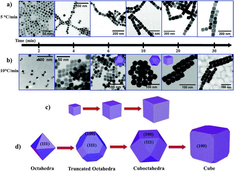
To understand the growth mechanism of cubic shape Fe3O4 NPs, we collected intermediate reaction products from the reaction mixture at different time intervals and analyzed them by TEM. At low heating rates (i.e. 5 °C min−1), we noticed the cubic morphology of the NPs after a reaction time (t) of 2 min at 290 °C (Fig. 3a and see Fig. S6a, ESI†). As the reaction progresses further (4 min to 30 min), the size of the NPs increased from ∼13 nm to ∼58 nm while maintaining the cubic morphology (Fig. 3a and see Fig. S6b–f, ESI†). In the case of a rapid heating rate (i.e. 10 °C min−1), we observe a rather different behavior compared to the reaction that occurred at a low heating rate. Here, we observed the emergence of small octahedral NPs after t = 2 min (Fig. 3b, left most panel, and see Fig. S7, ESI†). These octahedral NPs transformed into truncated octahedra after t = 4 min and 6 min (Fig. 3b and see Fig. S8, ESI†). At t = 10 min, these truncated octahedron NPs changed to a mixture of truncated octahedra and cuboctahedra shapes (see Fig. S9a and b, ESI†). Finally, these NPs gradually changed to NPs with a cubic morphology after 20 min reaction time (see Fig. S9c, ESI†) and we did not observe any further change in the morphology of the NPs (see Fig. S9d, ESI†). Therefore, the shape evolution of the NPs occurs in the first 20 min of the reaction, and, at the same time, the size of the NPs increases from ∼9 nm to ∼30 nm with an increase in the reaction time from 2 min to 30 min. These experimental results indicate that the heating rate influences the evolution of the cubic morphology of the Fe3O4 NPs via two different pathways. This can be explained based on the availability of monomers, and the balance between the chemical potential of the monomers (μm) and the chemical potential of different crystallographic planes.33 The chemical potential of the different crystallographic planes of Fe3O4 can be ranked as μ{100} > μ{110} > μ{111} because the {100} planes are the least densely packed and the {111} planes have the highest packing density. When the heating rate is low, the precursor decomposes slowly over the time period, resulting in a sluggish rate of nucleation (low concentration of nuclei in the nucleation stage). As the reaction enters the growth stage, the growth rate of preformed nuclei is very slow due to a low concentration of available monomers (i.e. a lower conversion rate of the precursor to monomers). In this case, the chemical potential of the monomers falls below the chemical potential of {100} and {110} (μ{100} > μ{110} > μm > μ{111}). The continuous deposition of monomers along the {111} planes thus leads to the formation of cubic shaped Fe3O4 NPs, and subsequently to growth of cubic NPs as the reaction progresses further (Fig. 3c).
At faster heating rates, the high rate of precursor decomposition leads to a faster nucleation rate (i.e. a large number of nuclei), as well as providing a high concentration of monomers available for growth of the NPs. In this case, the chemical potential of the monomers is initially higher than that of the crystallographic planes (i.e. μm > μ{100} > μ{110} > μ{111}), so the growth occurs simultaneously along all planes. The chemical potential of the monomers drops due to consumption of monomers in the reaction as the reaction advances (μ{100} > μm > μ{110} > μ{111}). As a result, this leads to the growth of octahedral and truncated octahedron NPs. In the later stage of growth, the chemical potential of the monomers falls to the point where μ{100} > μ{110} > μm > μ{111}. Therefore, the NPs grow more rapidly along the {111} planes and the shape of the NPs gradually changes from truncated octahedra (a larger proportion of {111} facets than {100} facets) to cuboctahedra (a larger proportion of {100} facets than {111} facets), and finally to cubic shape NPs (Fig. 3d).
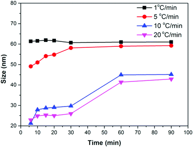
We performed several synthesis reactions at different heating rates and reaction times. The relationship between the time and size of Fe3O4 NPs at different heating rates is shown in Fig. 4. A small or no change in the size of the NPs can be noticed with time at low heating rates (1 °C min−1 and 2 °C min−1). However, the NP size continuously increases in the first 60 min of the reaction at high heating rates (1 °C min−1 and 2 °C min−1). After 60 min, a small increase in the size can be seen. These results suggest that the nucleation occurs at a lower temperature than 290 °C in the case of a low heating rate. The nuclei formed at low temperature consume monomers and quickly evolve into larger NPs, preventing further nucleation events at high temperature. A high heating rate promotes nucleation at high temperature (290 °C), and produces a large number of nuclei. The monomer concentration decreases due to the consumption by growing nuclei at the initial stage of the growth process, thus preventing nucleation events at the later stage of the reaction. In the later stage, the growth of NPs most likely occurs by an Ostwald ripening process, whereby either monomers from high surface energy facets or smaller NPs of high surface energy dissolve into the solution and redeposit on low surface energy facets or NPs. As a result, NPs of smaller sizes are produced at a high heating rate because of the low monomer concentration in the later stage of the reaction.
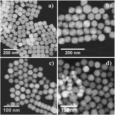
We also investigated the influence of a commonly neglected reaction parameter, the residual oxygen content in the reaction environment, on the shape of Fe3O4 NPs. The content of residual oxygen was controlled by degassing the reaction solution at different pressures. On increasing the degassing pressure from 0.19 mbar to 0.40 mbar and 0.71 mbar while under similar reaction conditions (5 °C min−1 and 290 °C), truncated cubic (58 nm, SD ∼ 9%) and truncated octahedra (∼57 nm, SD ∼ 4%) shape Fe3O4 NPs formed (Fig. 5a and b). When the reaction was performed at a higher heating rate (10 °C min−1) at a degassing pressure of 0.40 mbar and 0.71 mbar at similar reaction conditions, truncated octahedron NPs of size ∼38 nm and ∼37 nm (SD ∼ 8%) were obtained (Fig. 5c and d). The inset SEM images shown in Fig. 5c and d confirm the truncated octahedron morphology of the NPs. Moreover, the size of the truncated octahedron Fe3O4 NPs depends on the heating rate at similar reaction conditions (degassing pressure ∼0.71 mbar, 290 °C), i.e. a low heating rate resulted in a large size of octahedral NPs (∼57 nm) compared to the size obtained at a faster heating rate (∼37 nm). These results suggest that the synthesis of Fe3O4 NPs is very sensitive to the change in the content of residual oxygen in the reaction environment. According to first-principles calculations, the Wulff shape of an oxide material in thermodynamic equilibrium at low pressure and high temperature is a cube with [100] edges.27 In the case of Fe3O4 crystals, the cationic charge density of the {111} plane is higher than the other planes {110} and {100}. On increasing the pressure, oxygen species present in the reaction environment strongly adsorb onto the plane of high charge density, i.e. {111}, thus modifying the surface energy of the facets, i.e. γ(111) < γ(100) < γ(110). As a result, the growth of NPs is suppressed in the 〈111〉 direction, and a truncated octahedron shape possessing both (100) and (111) facets formed under thermodynamic equilibrium with oxygen species at the reaction temperature. Therefore, the shape of the NPs can be tailored by controlling the amount of residual oxygen (i.e. the degassing pressure).
The amount of solvent can have an influence on the shape and size of Fe3O4 NPs. To examine this, we varied the amount of BE solvent (10 mL, 20 mL, and 50 mL) and different reactions were performed at a heating rate of 10 °C min−1 (T = 290 °C, t = 30 min, degassing pressure = 0.19 mbar). BF STEM images show the formation of cubic shape Fe3O4 NPs of different sizes, i.e. 86 nm and 35 nm corresponding to 10 mL and 20 mL volume of the solvent (see Fig. S10a, ESI,† and Fig. 2d). When the amount of solvent was increased to 50 mL, we observed a flower morphology of Fe3O4 NPs of size ∼31 nm (see Fig. S10b, ESI†). These flower shaped NPs are formed by joining of two, three, or more than three small individual NPs. Therefore, these NPs can also be termed as single twinned or multiply twinned. The observed decrease in size with the increase in solvent volume can be explained by a reduction in the concentration of available monomers in the reaction. In the case of a low solvent volume (10 mL), the probability of finding monomers in the close vicinity of growing NPs is high, which facilitates higher mass transfer and, subsequently, a high growth rate. When the solvent volume is increased to 50 mL, the concentration of the precursor and thus the concentration of monomers in the solution is reduced. As a result, small size NPs are formed because of a sluggish growth rate. Since small NPs possess high surface energy, therefore, smaller NPs join to form a flower morphology, including single and multiple twinned Fe3O4 NPs, to minimize the overall surface energy.
In conclusion, we have demonstrated shape-and size-controlled synthesis of Fe3O4 NPs via thermal decomposition of Fe(acac)3 in the presence of OA and BE without any additional need for using a combination of solvents and ligands. When the reaction mixture was degassed at low pressure, Fe3O4 nanocubes formed, and their sizes can be varied by changing the heating rate. Our results showed two different nanocube formation mechanisms depending on the heating rate, as the heating rate influences the production of available monomers in the solution. The shape of the Fe3O4 NPs changes from nanocubes to octahedra when the degassing pressure of the reaction mixture is increased. This transformation can be attributed to a modification in the surface energy of different crystalline facets in the presence of oxygen species. Our results suggest that the residual oxygen content in the reaction environment (or degassing pressure) is an essential experimental parameter that enables control over the shape as well as reproducibility in size from different batches. The shape and size of Fe3O4 NPs can also be controlled by changing the volume of the solvent. The size of the nanocubes increases with an increase in the volume of the solvent, and at a high amount of solvent Fe3O4 NPs of flower morphology resulted. The difference in the sizes and shapes can be understood based on the concentration of monomers in the reaction mixture and mass transfer of monomers. Overall, these findings provide new conceptual insights and design rules for synthesizing Fe3O4 NPs with predetermined magnetic properties suited for specific applications such as magnetic hypothermia, contrast agents, photocatalysis, sensing, and energy storage.
Conflicts of interest
There are no conflicts to declare.Acknowledgements
The Research Council of Norway is acknowledged for the support of the Norwegian Micro- and Nano-Fabrication Facility, NorFab (197411/V30). The reported study was funded by RFBR, project number 20-37-70007.References
- A. Demortière, P. Panissod, B. P. Pichon, G. Pourroy, D. Guillon, B. Donnio and S. Bégin-Colin, Nanoscale, 2011, 3, 225–232 RSC.
- W. Wu, Z. Wu, T. Yu, C. Jiang and W. S. Kim, Sci. Technol. Adv. Mater., 2015, 16, 023501 CrossRef PubMed.
- H. Guo, Y. Zhang, W. Liang, F. Tai, Q. Dong, R. Zhang, B. Yu and W. Y. Wong, J. Inorg. Biochem., 2019, 192, 72–81 CrossRef CAS PubMed.
- D. Obermayer, A. M. Balu, A. A. Romero, W. Goessler, R. Luque and C. O. Kappe, Green Chem., 2013, 15, 1530–1537 RSC.
- Z. Meng, F. Xiao, Z. Wei, X. Guo, Y. Zhu, Y. Liu, G. Li, Z.-Q. Yu, M. Shao and W.-Y. Wong, Nano Res., 2019, 12, 2954–2959 CrossRef.
- P. Saharan, G. R. Chaudhary, S. K. Mehta and A. Umar, J. Nanosci. Nanotechnol., 2014, 14, 627–643 CrossRef CAS PubMed.
- H. Lian, Z. Tang, H. Guo, Z. Zhong, J. Wu, Q. Dong, F. Zhu, B. Wei and W.-Y. Wong, J. Mater. Chem. C, 2018, 6, 4903–4911 RSC.
- Z. F. Dou, C. Y. Cao, Q. Wang, J. Qu, Y. Yu and W. G. Song, ACS Appl. Mater. Interfaces, 2012, 4, 5698–5703 CrossRef CAS PubMed.
- P. Guardia, A. Labarta and X. Batlle, J. Phys. Chem. C, 2011, 115, 390–396 CrossRef CAS.
- J. Muro-Cruces, A. G. Roca, A. López-Ortega, E. Fantechi, D. del-Pozo-Bueno, S. Estradé, F. Peiró, B. Sepúlveda, F. Pineider, C. Sangregorio and J. Nogues, ACS Nano, 2019, 13, 7716–7728 CrossRef CAS PubMed.
- Z. Zhou, X. Zhu, D. Wu, Q. Chen, D. Huang, C. Sun, J. Xin, K. Ni and J. Gao, Chem. Mater., 2015, 27, 3505–3515 CrossRef CAS.
- Z. Nemati, J. Alonso, I. Rodrigo, R. Das, E. Garaio, J. Á. García, I. Orue, M.-H. Phan and H. Srikanth, J. Phys. Chem. C, 2018, 122, 2367–2381 CrossRef CAS.
- P. Hugounenq, M. Levy, D. Alloyeau, L. Lartigue, E. Dubois, V. Cabuil, C. Ricolleau, S. Roux, C. Wilhelm, F. Gazeau and R. Bazzi, J. Phys. Chem. C, 2012, 116, 15702–15712 CrossRef CAS.
- Z. Zhao, Z. Zhou, J. Bao, Z. Wang, J. Hu, X. Chi, K. Ni, R. Wang, X. Chen, Z. Chen and J. Gao, Nat. Commun., 2013, 4, 2266 CrossRef PubMed.
- G. Singh, B. H. McDonagh, S. Hak, D. Peddis, S. Bandopadhyay, I. Sandvig, A. Sandvig and W. R. Glomm, J. Mater. Chem. B, 2017, 5, 418–422 RSC.
- P. Guardia, R. Di Corato, L. Lartigue, C. Wilhelm, A. Espinosa, M. Garcia-Hernandez, F. Gazeau, L. Manna and T. Pellegrino, ACS Nano, 2012, 6, 3080–3091 CrossRef CAS PubMed.
- Y. Geng, P. Dalhaimer, S. Cai, R. Tsai, M. Tewari, T. Minko and D. E. Discher, Nat. Nanotechnol., 2007, 2, 249–255 CrossRef CAS PubMed.
- G. Singh, H. Chan, A. Baskin, E. Gelman, N. Repnin, P. Král and R. Klajn, Science, 2014, 345, 1149 CrossRef CAS PubMed.
- V. Håkonsen, G. Singh, J. He and Z. Zhang, Mater. Horiz., 2018, 5, 1211–1218 RSC.
- V. Håkonsen, G. Singh, P. S. Normile, J. A. De Toro, E. Wahlström, J. He and Z. Zhang, Adv. Funct. Mater., 2019, 29, 1904825 CrossRef.
- A. K. Ganguli, A. Ganguly and S. Vaidya, Chem. Soc. Rev., 2010, 39, 474–485 RSC.
- W. Zhang, S. Jia, Q. Wu, J. Ran, S. Wu and Y. Liu, Mater. Lett., 2011, 65, 1973–1975 CrossRef CAS.
- F. Ooi, J. S. DuChene, J. Qiu, J. O. Graham, M. H. Engelhard, G. Cao, Z. Gai and W. D. Wei, Small, 2015, 11, 2649–2653 CrossRef CAS PubMed.
- G. Muscas, G. Singh, W. R. Glomm, R. Mathieu, P. A. Kumar, G. Concas, E. Agostinelli and D. Peddis, Chem. Mater., 2015, 27, 1982–1990 CrossRef CAS.
- Z. Meng, C.-L. Ho, H.-F. Wong, Z.-Q. Yu, N. Zhu, G. Li, C.-W. Leung and W.-Y. Wong, Sci. China Mater., 2019, 62, 566–576 CrossRef CAS.
- Q. Dong, Z. Meng, C. L. Ho, H. Guo, W. Yang, I. Manners, L. Xu and W. Y. Wong, Chem. Soc. Rev., 2018, 47, 4934–4953 RSC.
- Z. Meng, G. Li, H. F. Wong, S. M. Ng, S. C. Yiu, C. L. Ho, C. W. Leung, I. Manners and W. Y. Wong, Nanoscale, 2017, 9, 731–738 RSC.
- A. Nikitin, M. Khramtsov, A. Garanina, P. Mogilnikov, N. Sviridenkova, I. Shchetinin, A. Savchenko, M. Abakumov and A. Majouga, J. Magn. Magn. Mater., 2019, 469, 443–449 CrossRef CAS.
- D. Kim, N. Lee, M. Park, B. H. Kim, K. An and T. Hyeon, J. Am. Chem. Soc., 2009, 131, 454–455 CrossRef CAS PubMed.
- G. Singh, P. A. Kumar, C. Lundgren, A. T. J. van Helvoort, R. Mathieu, E. Wahlström and W. R. Glomm, Part. Part. Syst. Charact., 2014, 31, 1054–1059 CrossRef CAS.
- M. Klinger and A. Jager, J. Appl. Crystallogr., 2015, 48, 2012–2018 CrossRef CAS PubMed.
- J. Polte, CrystEngComm, 2015, 17, 6809–6830 RSC.
- L. Qiao, Z. Fu, J. Li, J. Ghosen, M. Zeng, J. Stebbins, P. N. Prasad and M. T. Swihart, ACS Nano, 2017, 11, 6370–6381 CrossRef CAS PubMed.
Footnote |
| † Electronic supplementary information (ESI) available: Experimental method, and XRD, SEM and TEM images of magnetic nanoparticles. See DOI: 10.1039/d0ma00275e |
| This journal is © The Royal Society of Chemistry 2020 |

