
 Open Access Article
 This Open Access Article is licensed under a
 Creative Commons Attribution 3.0 Unported Licence
Investigation of the photoluminescence and novel thermoluminescence dosimetric properties of NaGdF4:Tb3+ phosphors†
Preeti Padhye
Kulkarni
a,
Kishor H.
Gavhane
a,
Mahesh S.
Bhadane
b,
Vasant N.
Bhoraskar
a,
Shailendra S.
Dahiwale
a and
Sanjay D.
Dhole
 *a
*a
aMicrotron Accelerator Laboratory, Department of Physics, Savitribai Phule Pune University, Pune, 411007, MH, India. E-mail: sanjay@physics.unipune.ac.in
bDepartment of Physics, Rayat Shikshan Sanstha's Dada Patil Mahavidyalaya, Karjat, 414402, MH, India
First published on 23rd June 2020
Abstract
The hexagonal phase β-NaGdF4:x% Tb3+ (x = 0 to 5%) phosphor crystals with uniform morphology and considerable monodispersity were synthesized via a tri-sodium citrate-assisted hydrothermal route. The photoluminescence studies showed the strong emission lines corresponding to 5D4 → 7FJ (J = 6, 5, 4, 3) transitions with a prominent 5D4 → 7F5 green emission transition at 540 nm. The as-prepared samples were annealed at different temperatures (200–800 °C), and the effect of thermal treatment on their structural, morphological, surface, photoluminescence and thermoluminescence properties were studied. A comparative study of pristine and annealed samples revealed phase alteration to the mixed (i.e. cubic and hexagonal) phase along with morphology transformation at higher annealing temperatures. The photoluminescence emission intensity was remarkably enhanced (∼9 times) at 700 °C owing to the reduction in non-radiative processes from the surface and the volatilization of luminescence quenching (–OH) groups, which were corroborated by surface FTIR studies. The systematic study of the optimum concentrations of impurities and thermal treatment were studied to achieve high thermoluminescence (TL) efficiency. The best TL dosimetric glow curve was obtained for NaGdF4:3% Tb3+ annealed at 700 °C, which peaked at 230 °C, signifying deeper traps. The NaGdF4:3% Tb3+ phosphor showed a linear response over a very wide range of gamma doses from 100 Gy to 20 kGy, revealing that the NaGdF4:Tb3+ phosphor was quite well suited for high gamma dose measurements and their respective applications. Fading and reproducibility studies showed low fading and excellent reproducibility characteristics. The Tm–Tstop technique in combination with the Initial Rise Method (IRM) was used to identify the number of overlapped TL glow peaks and trap level analysis. The kinetic parameters, such as activation energy (E), frequency factor (s), and order of kinetics (b), were estimated by the Glow Curve Deconvolution (GCD) method. The Figure of Merit (FOM) value was found to be 2.2%. The trapping parameters resulting from the experimental Tm–Tstop study and theoretical GCD match closely and are in good agreement with each other. Thus, along with high luminescence efficiency, the newly explored strong thermoluminescence properties of NaGdF4:Tb3+ make them potential phosphor materials and could provide new avenues into other applications in radiation dosimetry such as agriculture/food sciences, archeological sciences, space dosimetry, etc.
1. Introduction
Thermoluminescence (TL) is the emission of light from a crystalline material that is either inorganic, a semiconductor, or an insulator when it is heated after its exposure to some ionizing radiation.1 Accordingly, when any ionizing radiation is incident upon a crystal, some energy is dissipated by various processes such as heat and light and some amount of energy is absorbed and stored in the lattice at the luminescent centers or defect sites, etc. Upon subsequent heating of the crystal, this stored energy is released and a fraction of it can be emitted as visible light in form of a TL glow curve/peak.2 The positions, shapes and intensities of the glow peaks are related to the various TL parameters, which provide very valuable information about the trapped states/charges and energy transfer processes in a crystalline lattice resulting in the emission of light.3 It is a very powerful technique that is used for dose measurement, i.e., estimations of doses of ionizing radiation, as the energy absorbed by the phosphor during irradiation and the TL intensity on stimulation (heating) is proportional to the radiation doses.4 The dosimetric properties of TL materials mainly depend on the kinetic parameters of its glow peak. Kinetic parameters provide valuable information about the thermoluminescence mechanism in a material. The most significant TL parameters, namely, trap depth (E) or the activation energy, which is the thermal energy required to liberate the trapped electrons and holes, the order of kinetics (b) and the frequency factor (s), can be evaluated by TL glow peak analysis. Existing methods for peak analysis and activation energy (E) and frequency factor (s) determination are principally comprised of Peak Shape (PS), Initial Rise (IR), Isothermal Decay (ID), and Variable Heating Rate (VHR) methods.5,6Thermoluminescence dosimetry (TLDs) materials have found many useful applications in various fields of radiation dosimetry in personnel and environmental monitoring, medical/clinical dosimetry, agriculture/food irradiation sciences, i.e. dose measurement in food preservation, radiation sterilization of seed, etc., archeological sciences, high-dose dosimetry, retrospective dosimetry and space dosimetry.2,7
A number of thermoluminescent dosimeters (TLD)-based systems are now commercially available. CaSO4:Dy (TLD-900), LiF-based phosphors such as LiF:Mg,Cu,P (LiF-TLD 700H), LiF:Mg,Ti (TLD-100), Li2B4O7:Mn (TLD-800), CaF2:Dy (TLD-200), Al2O3:C, are efficient and commercially available phosphors.2,8–10 However, owing to the increasing use of the TL technique, efforts are still being made to improve the TL characteristics and sensitivity of phosphor materials either by thermal treatment or by impurity doping. Attempts are also being made to develop new phosphor materials with improved TL characteristics.
It is worth mentioning that lanthanide ion-doped luminescent nanomaterials, specifically sodium rare-earth fluoride (NaREF4:Ln3+) phosphors, are receiving a great deal of interest in the field of science and technology due to their highly efficient and extraordinary photoluminescence properties. The lanthanide ion-doped phosphors have been extensively studied owing to their fascinating wide range of applications in multicolor displays, opto-electronics, lasers, solar cells, photocatalysis, biomedical sciences, theranostics probes, sensing, anti-counterfeiting, security printing, etc.11–16 The outstanding intricate spectroscopic properties of Ln3+-doped phosphors originates from parity forbidden intra f–f transitions that are shielded by filled 5s2 and 5p6 orbitals.17 This unique electronic configuration renders fascinating properties to these materials, such as emissive transitions in a broad spectral region, less sensitivity to the surrounding environment, large Stokes and anti-Stokes shifts (>200 nm), sharp and narrow emission bands (FWHM ∼ 10 nm), long-lived luminescence (milliseconds), low intermittency and background fluorescence, and high photostability.18–20
Since lanthanide dopants suffer from low molar absorption coefficients (ε = 1–10 M−1 cm−1),21 for efficient electronic transitions between rare-earth energy levels and to effectively utilize the novel luminescence of lanthanide dopant ions, it is necessary to choose appropriate host lattice materials. Fluoride host materials provide some distinct advantages as compared to oxide materials or other rare-earth compounds such as sulphates, phosphates, and vanadates, owing to their unique properties like high coordination number, high ionicity of rare earth-to-fluorine (RE3+–F−) bonds, intrinsic low phonon energy, wide band gap, chemical stability, electron acceptor behavior, and anionic conductivity.22,23 Among the various investigated fluoride host materials, sodium rare-earth fluorides (NaREF4), particularly NaGdF4, are of special interest. The NaGdF4 is considered as one of the most versatile and outstanding host materials because of its excellent luminescence efficiency due to half-filled 4f orbitals resulting in minimal non-radiative electronic transitions, wide band gap, high refractive index, low phonon energy, and chemical, thermal, and environmental stability.24 Also, the Gd3+ ion serves as an ideal sensitizer or intermediate to activate the specific luminescence of Ln3+ ions via the non-radiative energy transfer mechanism, inducing intense emissions in the visible region. Moreover, the presence of Gd3+ renders paramagnetic properties; thus, the Ln3+ doped β-NaGdF4 phosphors can be used as multifunctional magneto-luminescent probes.25,26
In this contribution, we report the structural, morphological, photoluminescence and thermoluminescence properties of NaGdF4:Tb phosphors synthesized via the tri-sodium citrate-assisted hydrothermal route. NaGdF4:x% Tb (x = 0 to 5%) were prepared and their structural, morphological and photoluminescence properties were studied. It is well demonstrated that thermoluminescence properties in the phosphor material are greatly modified by the type of impurity/dopant, its concentration and the thermal treatment. Enlightened by this point, to explore and optimize the NaGdF4:x% Tb phosphor for efficient thermoluminescence properties, we attempted to anneal the as-prepared NaGdF4:x% Tb phosphor samples at different temperatures from 200–800 °C. The photoluminescence properties are also greatly influenced by the thermal treatment,27 thus, the influence of thermal treatment on the structural, morphological, surface and photoluminescence properties of NaGdF4:Tb phosphors were also studied. Thermoluminescence glow curves, dose responses, fading characteristics, and reproducibility were studied. The number of glow peak components and trapping parameters/kinetic parameters such as the activation energy and kinetics order were investigated experimentally by Tm–Tstop analysis in combination with the initial rise method (IRM), the activation energy-Tstop method and theoretically by the glow curve deconvolution (GCD) method. Potential photoluminescence, magnetic properties and consequent applications of NaGdF4 phosphors have been explored to some extent. Thermoluminescent dosimetric applications are an important field of science and technology. However, unfortunately, no serious attention has been paid to exploring the thermoluminescence dosimetric properties of Tb3+-doped NaGdF4 phosphors in the literature to date. To the best of our knowledge, for the first time, we report the thermoluminescence dosimetric properties of the gamma-irradiated NaGdF4 phosphor activated by Tb3+ ions.
2. Materials and methods
2.1 Materials
All the chemicals were of analytical grade and were used as-received without any further purification. The rare earth oxides, gadolinium oxide (Gd2O3) (purity ≥99.89%), and terbium oxide (Tb2O3) (purity ≥99.89%) were purchased from Sigma Aldrich Inc. Sodium fluoride (NaF) and tri-sodium citrate dihydrate ((Na3C6H5)7·2H2O) were received from Thomas Baker Chemicals Pvt. Ltd. Deionized water was used throughout the experiments. Rare earth nitrate stock solutions were prepared by dissolving the corresponding rare earth oxides (Gd2O3 and Tb2O3) in nitric acid at elevated temperatures (∼80 °C).2.2 Synthesis
All of the doping ratios of Ln3+ are molar in our experiments. In a typical procedure for the preparation of β-NaGdF4:x% Tb3+ (x = 0, 0.5, 1, 2, 3, 4, 5%) crystals, aqueous solutions of Gd(NO3)3 and Tb(NO3)3 (0.2 M) were added into 30 mL of aqueous solution containing 2 mmol of tri-sodium citrate (0.5882 g) to form the metal–citrate complex. After vigorous stirring, 2 M of NaF solution was added drop-wise into the above solution under stirring. After agitation for several minutes, the solution was transferred into a stainless steel autoclave with Teflon liner of 80 mL capacity, sealed and heated at 180 °C for 24 h. After that, the autoclave was cooled to room temperature and the resulting product was separated centrifugally and washed several times with distilled water and absolute ethanol. The product was dried under vacuum at 80 °C for 8 h. Some parts of the as-prepared samples were annealed at different temperatures ranging from 200 to 800 °C in an ambient atmosphere at the heating rate of 2 °C min−1 for 2 h.2.3 Characterization techniques
The phase purity and crystallinity of the as-prepared samples were characterized by powder X-ray diffraction (PXRD) using a Bruker AXSD8 Advance X-ray diffractometer and the iron-filtered Cu-Kα radiation (λ = 1.54 Å) in the 2θ range of 10°–80°. To analyze the shape and size of the samples, a Field Emission Scanning Electron Microscope (FESEM) NOVA NANOSEM 450 was used. The surface studies were performed on a JASCO FT/IR 6100 instrument. PL spectra were acquired using a Fluorolog Horiba-1057 fluorescence spectrophotometer, equipped with a 400 W Xe lamp as an excitation source and a Hamamatsu R928 photomultiplier tube (PMT) as the detector. Thermoluminescence measurements of the TL glow spectra of the phosphor material were carried out by using a Nucleonix TLD Reader (Model 1009I) with a constant 5 mg weight of the phosphor sample at a constant heating rate of 5 °C s−1. For thermoluminescence studies, the phosphor materials were irradiated to gamma rays. The activity of the 60Co gamma source was 2456 Curie on 14 March 2013 (dose rate = 60 Gy min−1). Its half-life = 5.27 years. The dose rate of the gamma source (at distance 6 cm) = 389![[thin space (1/6-em)]](https://www.rsc.org/images/entities/char_2009.gif) 000 R h−1 = 3412 Gy h−1 = 55 Gy min−1. The gamma source emits two gamma quanta having energies 1.17 MeV and 1.33 MeV. In TL processes, the heat treatment is done before irradiation, which is necessary to erase any irradiation memory from the dosimetric material. Before irradiation and after irradiation all the samples were kept inside the black box, which prevents external or environmental effects on the TL samples.
000 R h−1 = 3412 Gy h−1 = 55 Gy min−1. The gamma source emits two gamma quanta having energies 1.17 MeV and 1.33 MeV. In TL processes, the heat treatment is done before irradiation, which is necessary to erase any irradiation memory from the dosimetric material. Before irradiation and after irradiation all the samples were kept inside the black box, which prevents external or environmental effects on the TL samples.
3. Results and discussion
3.1 Structural and morphological investigations of NaGdF4:Tb3+ phosphors
The composition, crystallinity and phase purity of the as-prepared phosphors were first examined by XRD. Fig. 1(a–g) compares typical XRD patterns of the as-synthesized NaGdF4:x% Tb3+ (x = 0, 0.5, 1, 2, 3, 4, and 5) phosphors. All of the samples exhibited sharp diffraction peaks that can be readily indexed to the pure hexagonal-phase β-NaGdF4 (space group: P63/m). The calculated lattice parameters are a = 6.0 Å, c = 3.6 Å, which are in good agreement with the reported data (JCPDS no. 27-0699). No secondary phase was observed in the XRD patterns, revealing that the Tb3+ ions have been effectively doped into the β-NaGdF4 host lattice without any phase transformation.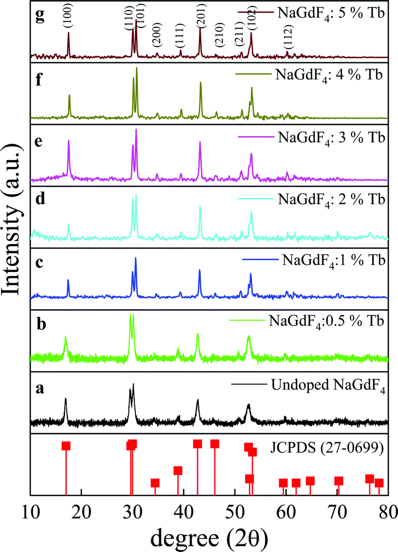 | ||
| Fig. 1 The XRD patterns of β-NaGdF4:x% Tb3+ (x = 0, 0.5, 1, 2, 3, 4, 5) (a–g) and the standard data of the hexagonal β-NaGdF4 (JCPDS- 27-0699) as a reference. | ||
The size and morphology of the as-prepared samples were characterized by field emission scanning electron microscopy (FESEM). As shown in Fig. 2(a–g), β-NaGdF4:x% Tb3+ crystals possess a highly uniform and monodispersed spherical-shaped structure with an average diameter of ∼300 nm.
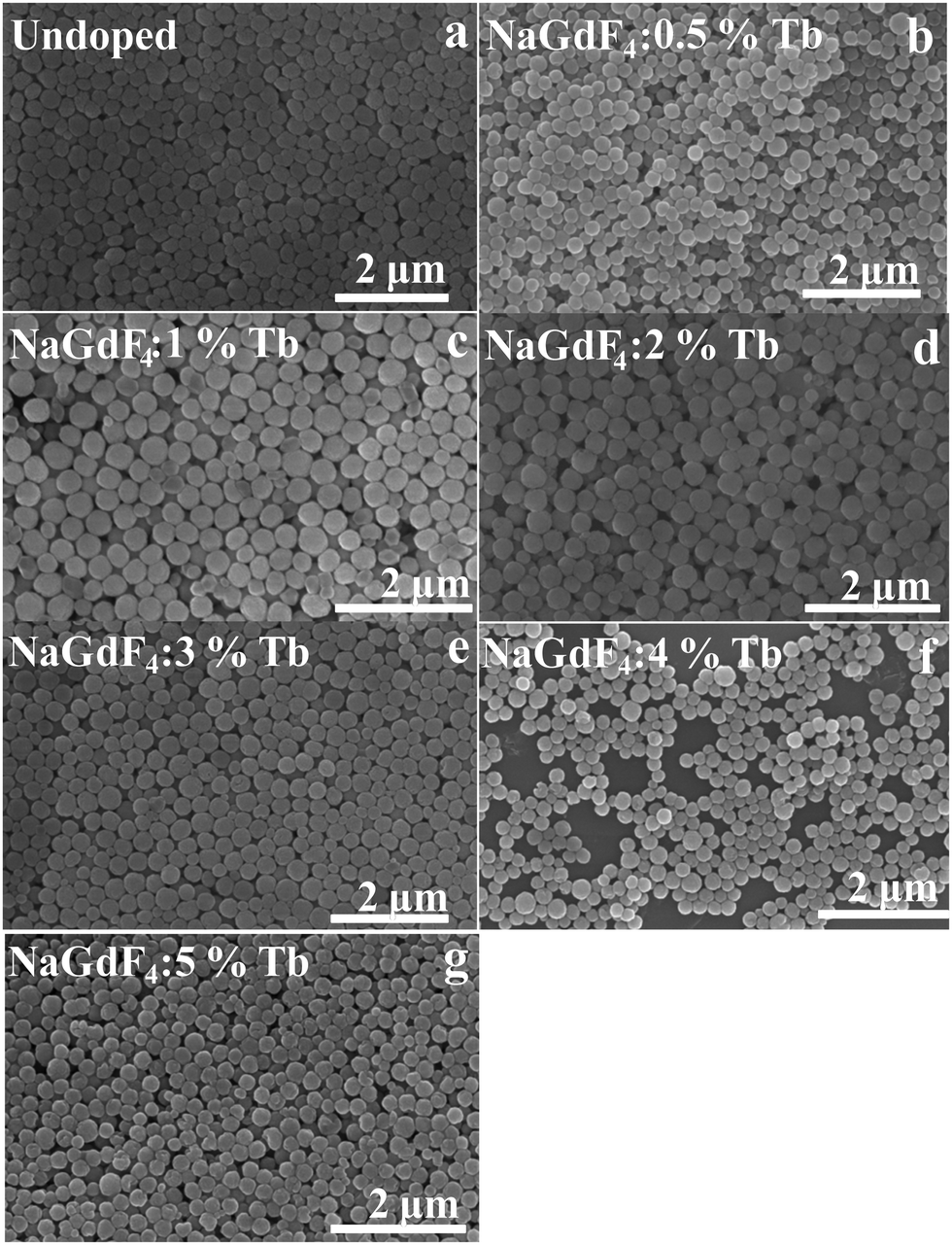 | ||
| Fig. 2 The FESEM images of β-NaGdF4:x% Tb3+ crystals (x = 0, 0.5, 1, 2, 3, 4, 5) (a–g) showing the spherical morphology of the as-prepared β-NaGdF4:x% Tb3+ phosphors. | ||
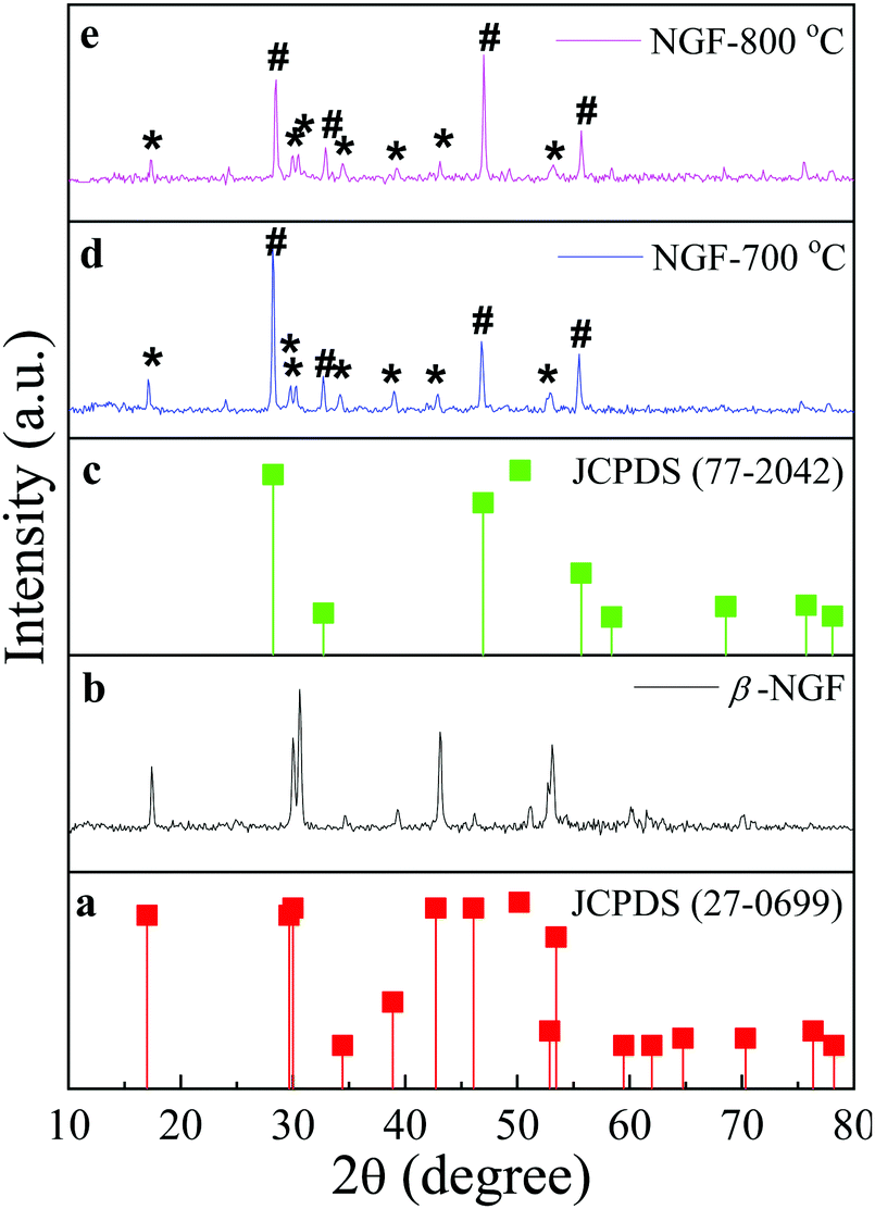 | ||
| Fig. 3 The XRD patterns of the NaGdF4:3% Tb3+ phosphor crystals obtained after annealing at different temperatures for 2 h, labelled as β-NGF (b) for the as-prepared pristine pure hexagonal phase NaGdF4:Tb3+ phosphor and annealed samples labelled as NGF-X (X = 700 °C and 800 °C) (d and e). The standard data of hexagonal β-NaGdF4 (JCPDS- 27-0699) and cubic phase α-NaGdF4 (JCPDS- 77-2042) (a and c) as a reference. Diffraction peaks corresponding to the hexagonal phase β-NaGdF4 are marked with an asterisk (*) and peaks for the cubic phase α-NaGdF4 are marked with a hash (#). | ||
The effects of annealing on the morphology of the as-prepared phosphors were also studied and are shown in Fig. 4(a–d). It can be clearly seen that the well-dispersed and uniform spherical morphology was transformed into irregular block-like structures of non-uniform size with increasing annealing temperatures.
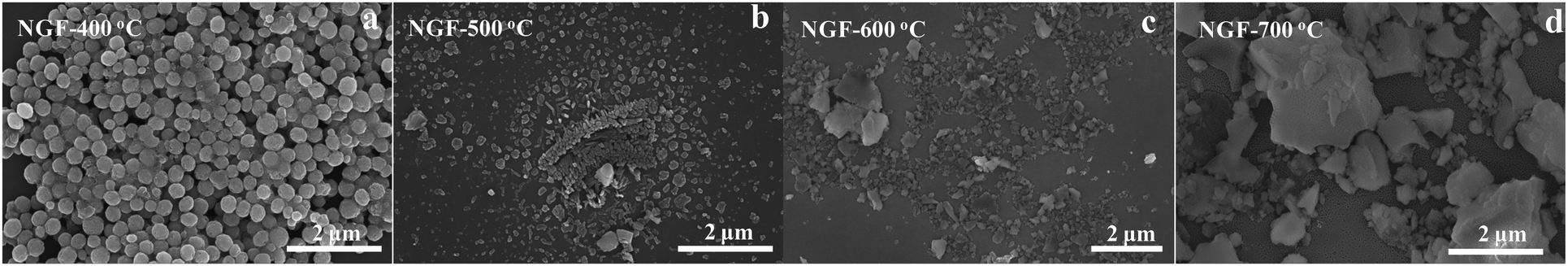 | ||
| Fig. 4 The FESEM images of NaGdF4:3% Tb3+ crystals; NGF-X (X = 400, 500, 600, 700 °C) (a–d) annealed at different temperatures for 2 h. At 700 °C, microblock-like structures were formed. | ||
Based on the above results, it can be inferred that the β-NGF samples remained in a stable state, and retained their original morphology and crystal structure at low temperatures. When annealed at a higher temperature of 700 °C, β-NaGdF4 crystals obtained enough energy to undergo a phase transformation from the hexagonal to the cubic phase and the NaGdF4 crystals fused into each other and agglomerated, giving rise to the irregular block-like morphology.
3.2 FTIR study
The FTIR spectra of the as-prepared, 500 and 700 °C-annealed 3% Tb3+-doped NaGdF4 phosphor crystals in the wavenumber range of 1000–4000 cm−1 are shown in Fig. 5. For the as-prepared NaGdF4 phosphor crystals, the band at ∼1586 cm−1 can be assigned to the C![[double bond, length as m-dash]](https://www.rsc.org/images/entities/char_e001.gif) O asymmetric stretching vibration of the –COO− group and the band at ∼1396 cm−1 corresponds to the symmetric stretching vibration of CO in –COO− group of tri-sodium citrate (TSC). This reveals the capping of tri-sodium citrate on the surface of the as-prepared phosphor particles. A broad band at ∼3450 cm−1 could be ascribed to the stretching vibrations of –OH groups as well as to the presence of non-dissociated OH groups of citrate and molecular water present on the surface of phosphor particles.28,29 It can be clearly seen from Fig. 5 that the bands for –OH groups were diminished upon heat treatment, i.e., at the annealing temperatures of 500 and 700 °C. It was well demonstrated by TGA-DSC studies that the decomposition of tri-sodium citrate occurs in three steps at temperatures ranging from 160 °C to 700 °C.30,31 Accordingly, the FTIR spectra (Fig. 5) revealed that the intensity of the bands for the –COO− functional group of the TSC ligand was greatly reduced at 700 °C. These results suggest the decomposition of surface ligands at higher annealing temperatures that may lead to the agglomeration of particles, resulting in the increase in particle size as revealed by FESEM images.
O asymmetric stretching vibration of the –COO− group and the band at ∼1396 cm−1 corresponds to the symmetric stretching vibration of CO in –COO− group of tri-sodium citrate (TSC). This reveals the capping of tri-sodium citrate on the surface of the as-prepared phosphor particles. A broad band at ∼3450 cm−1 could be ascribed to the stretching vibrations of –OH groups as well as to the presence of non-dissociated OH groups of citrate and molecular water present on the surface of phosphor particles.28,29 It can be clearly seen from Fig. 5 that the bands for –OH groups were diminished upon heat treatment, i.e., at the annealing temperatures of 500 and 700 °C. It was well demonstrated by TGA-DSC studies that the decomposition of tri-sodium citrate occurs in three steps at temperatures ranging from 160 °C to 700 °C.30,31 Accordingly, the FTIR spectra (Fig. 5) revealed that the intensity of the bands for the –COO− functional group of the TSC ligand was greatly reduced at 700 °C. These results suggest the decomposition of surface ligands at higher annealing temperatures that may lead to the agglomeration of particles, resulting in the increase in particle size as revealed by FESEM images.
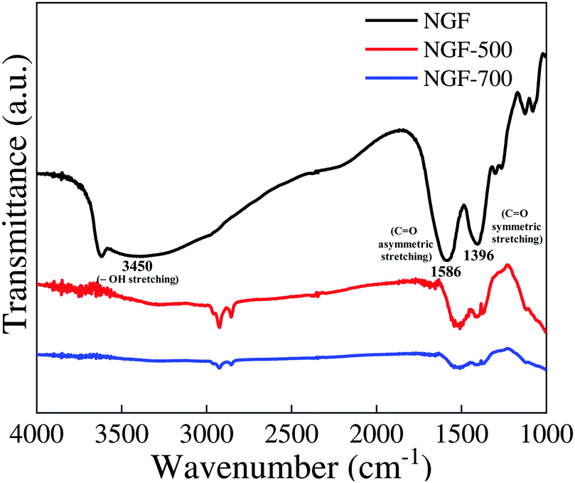 | ||
| Fig. 5 FTIR spectra of the as-prepared (NGF), 500 °C (NGF-500) and 700 °C (NGF-700) annealed NaGdF4:3% Tb3+ phosphor crystals. | ||
3.3 Photoluminescence studies of β-NaGdF4:Tb3+
Fig. 6 compares the excitation (a) and emission (b, c) photoluminescence spectra of Tb3+ ion-doped NaGdF4 crystals. No emission lines appeared for the undoped samples and in all the doped β-NaGdF4:x% Tb3+ (x = 0, 0.5, 1, 2, 3, 4, and 5) samples, the peak-positions in the excitation and emission spectra remained similar, and the bands differed only in their relative intensities. The excitation and emission intensities increased with increasing dopant concentration. The excitation spectrum monitored at λex = 540 nm had several excitation lines originating from the f–f transitions of Gd3+ and Tb3+ ions in the UV spectral region. The excitation lines at, ∼228 nm, ∼273 nm and ∼312 can be assigned to the transition from the 8S7/2 ground state to the excited states 6D9/2, 6I7/2, and 6P7/2 of Gd3+ ions.32,33 The weak excitation lines at ∼356 nm and ∼375 nm correspond to the transitions from the 7F6 ground state to the 5D2 and 5G6 excited states of Tb3+ ions, as shown by the arrow in the inset of Fig. 6(a).34 The obtained emission spectra monitored at λex = ∼228 nm and ∼273 nm showed intense emissions in the regions of 480–680 nm, which are due to the 5D4 → 7FJ (J = 3, 4, 5, 6) transitions of Tb3+ ions. Specifically, the four prominent emission peaks centered at ∼484, ∼540, ∼580, and ∼615 nm, originated from the transitions of 5D4 → 7F6, 5D4 → 7F5, 5D4 → 7F4, and 5D4 → 7F3, respectively.35 Among these transitions, the green emission 5D4 → 7F5 at ∼540 nm is the most intense emission, which corresponds to a magnetic dipole transition. Comparison of the excitation intensity bands of the β-NaGdF4:Tb3+ phosphor particles monitored at 540 nm showed that the intensity of the ∼228 nm 8S7/2 to 6D9/2 transition band was more intense than the other bands. From Fig. 6(d), the combination of the two emission intensity effects under excitation at 228 nm and 273 nm showed that the emission intensity of the emission spectrum monitored at 228 nm was enhanced dramatically as compared to emission intensity obtained under 273 nm excitation.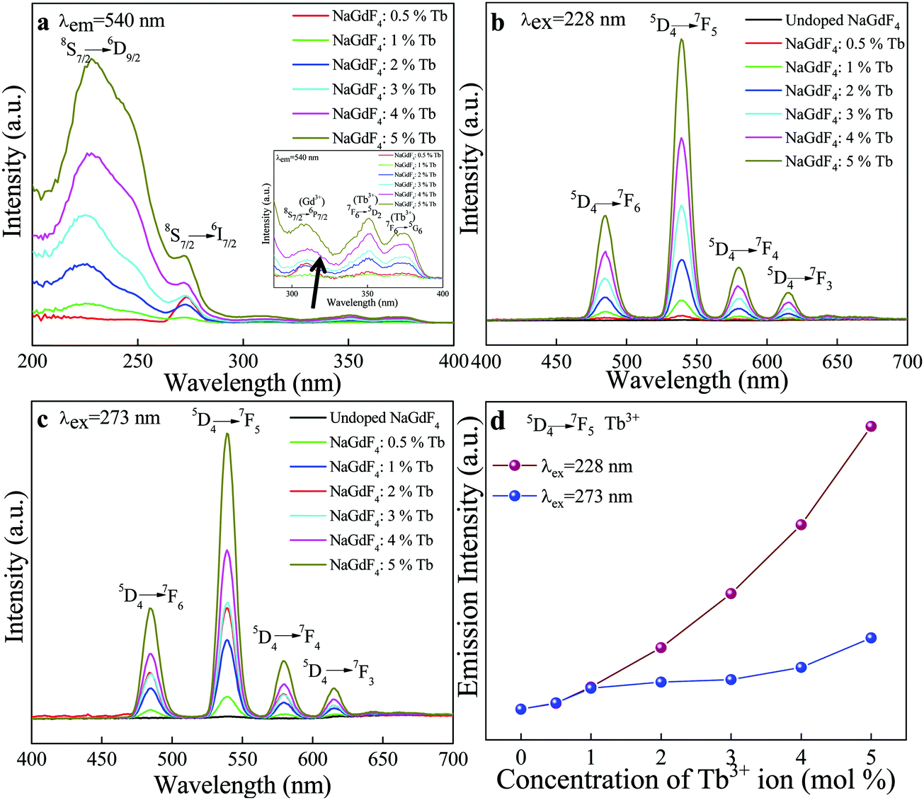 | ||
| Fig. 6 Comparison of the static photoluminescence excitation spectra monitored at λem = 540 nm (a), and emission spectra monitored at λex = 228 nm and λex = 273 nm (b and c) of β-NaGdF4:x% Tb3+ (x = 0, 0.5, 1, 2, 3, 4, 5) crystals with different concentrations. The photoluminescence intensity of the 5D4 → 7F5 transition of the Tb3+ ions as a function of dopant concentration (d) at different excitation wavelengths λex = 228 nm and λex = 273 nm. | ||
The optical properties of inorganic materials are strongly dependent on their size, morphology, doping, crystallinity, thermal treatment and other parameters, that affect the band structure. Among these, studies of the effects of thermal treatment in inorganic phosphor are rarely conducted.
 | ||
| Fig. 7 The photoluminescence emission spectra of the pristine NaGdF4:3% Tb3+ phosphor crystals and NaGdF4:3% Tb3+ phosphor annealed at 500 °C and 700 °C, monitored at λex = 228 nm. The emission intensity increased at higher annealing temperatures. | ||
4. Thermoluminescence dosimetric properties
4.1 Glow curve optimization
The thermoluminescence glow curve is a measure of the intensity of the emitted light as a function of temperature. These glow curve structures are of particular importance as they are the main indicators of whether or not a material can be employed for TL dosimetry. The favorable glow curve structure, TL sensitivity and luminescence efficiency are strongly influenced by the concentration of impurities/dopants and the thermal treatment of the phosphor material.38 Therefore, the investigation of the dependency of the glow curve structure on the dopants concentration and annealing temperatures is a significant research area in developing and exploring new TL materials. Keeping this point in mind, we conducted the optimization by annealing NaGdF4:x% Tb3+ (x = 0, 0.5, 1, 2, 3, 4, 5) phosphors at different temperatures from 200–800 °C for 2 h. Fig. S2(a–g) (ESI†) and Fig. 8 show typical TL glow curves of pristine NaGdF4:x% Tb3+ and annealed NaGdF4:x% Tb3+ phosphor irradiated by gamma radiation of dose 1 kGy from the 60Co gamma source. For the pristine NaGdF4:x% Tb3+ phosphor, an asymmetric TL peak appeared at around 340 °C (Fig. S2(a), ESI†). Upon successive thermal pretreatments at 200, 300 and 400 °C, almost all samples showed wide broadly distributed, multiple, low intensity and asymmetric TL peaks at 120, 250, and 340 °C, respectively (see Fig. S2(b–d), ESI†). As mentioned above, the TL peak shape and position are among the important deciding factors for a useful TLD material. At annealing temperatures 500 and 600 °C, for all doping concentrations, two peaks appeared: one at a lower temperature, 145 °C, with high intensity, and another low-intensity peak at 350 °C (Fig. S2(e and f), ESI†). Since the low-temperature peaks (145 °C) possess high intensity, this means that the samples possess increased numbers of shallow traps and are also likely to fade at faster rates and thus, are not suitable for long term measurements.39,40 Fig. S2(g) (ESI†) demonstrates the TL glow curves of samples annealed at 800 °C. For 0.5 and 1% Tb concentration, a single prominent TL glow peak was obtained at around 218 °C; however, it possessed a very broad distribution, which may consist of several overlapping peaks.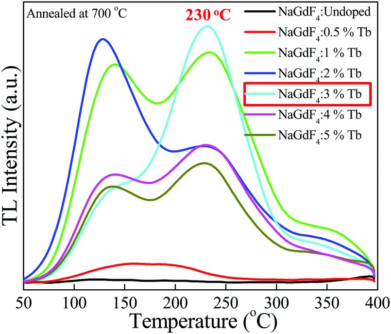 | ||
| Fig. 8 Thermoluminescence glow curve optimization of the NaGdF4:x% Tb3+ (x = 0, 0.5, 1, 2, 3, 4, 5) phosphor annealed at 700 °C, irradiated at a gamma dose of 1 kGy. NaGdF4:3% Tb3+ showed the most suitable glow curve at 230 °C. | ||
At annealing the temperature of 700 °C, two TL peaks were obtained for NaGdF4:x% Tb3+ (x = 1, 2, 4, 5), one at low temperature ∼145 °C and another at high temperature ∼230 °C. On comparing the TL glow curves of the NaGdF4:x% Tb3+ (x = 0, 0.5, 1, 2, 3, 4, 5) phosphor, pristine and annealed at different temperatures (200–800 °C), we obtained the most satisfactory and favorable results for the NaGdF4:3% Tb3+ phosphor annealed at 700 °C. As can be seen from Fig. 8, the NaGdF4:3% Tb3+ phosphor annealed at 700 °C showed the most intense appropriate Gaussian shape single-peak at 230 °C with a very small shoulder at around 145 °C. The absence of a low-temperature glow peak in NaGdF4:3% Tb3+ might be due to the elimination of surface traps in the phosphor sample. The high-temperature peak is suggestive of the presence of deeper traps in the phosphor sample, and consequent stable and efficient thermoluminescence dosimetric behavior. This TL feature obtained for the NaGdF4:3% Tb3+ phosphor annealed at 700 °C (i.e. dosimetric glow curve temperature position at 230 °C) is very close to commercially available standard thermoluminescence dosimetric materials such as LiF:Mg,Cu,Si, Li2B4O7:Mn, CaSO4:Dy or Tm.2,41
It is worth noting that no thermoluminescence glow curves appeared for undoped NaGdF4 crystals at any annealing temperature at the gamma dose of 1 kGy. Therefore, it is likely that the presence of Tb3+ dopant ions increases the number of trapping/luminescent centers in the host system, which results in the realization of thermoluminescence properties in the NaGdF4:Tb phosphor system. In general, the kinds of traps/luminescent centers created by γ-irradiation are mostly affected by the dopant concentration and annealing temperature; thus, the appropriate dopant concentration and annealing temperature help to maintain the defect equilibrium and stabilization of traps38 and consequently, the realization of thermoluminescence characteristics. In the present case, NaGdF4 doped with 3% concentration of Tb3+ ion annealed at 700 °C rendered the most favorable thermoluminescence properties; thus, we opted for the NaGdF4:3% Tb3+ phosphor annealed at 700 °C for further TL dosimetric characteristics such as dose–response, fading, reproducibility, trapping parameters and activation energy.
The crystal structure of hexagonal NaGdF4 has three different crystallographic sites for the Gd3+ and Na+ cations; these sites are called the 1a, 1f and 2h sites. The three types of cationic sites include a nine-fold coordinated position where the 1a site is occupied by Gd3+ ions, another nine-fold coordinated where 1f is occupied randomly by Gd3+ and Na+ ions, and a six-fold coordinated 2h site that is half occupied by Na+ ions and half vacancies. The two different Gd3+ sites are both coordinated by nine fluorine (F−) atoms in the form of tricapped trigonal prisms.42,43 The dopant Ln3+ (Tb3+ in present case) ions substitute for Gd3+ ion sites in the NaGdF4 crystal lattice.25 These vacancies and the dopant ions may act as trapping sites and radiative recombination centers.42,44 However, detailed study and useful insight are required to better understand the nature of the traps/sites, defects and radiative recombination centers associated with the NaGdF4: Tb phosphor system.
| I = a Db, |
| log(I) = log(a) + blog(D) |
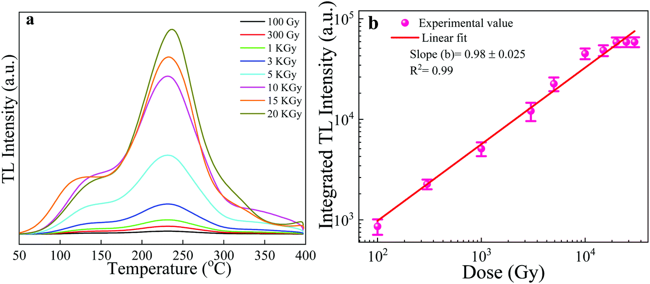 | ||
| Fig. 9 TL glow curves of the NaGdF4:3% Tb3+ phosphor irradiated with various doses (100 Gy to 20 kGy) of gamma rays from a 60Co source (a). Linear TL response of the NaGdF4:3% Tb3+ phosphor as a function of irradiation dose (b). | ||
It is worth mentioning that the as-synthesized NaGdF4:3% Tb phosphor showed linear behavior up to very higher doses of 20 kGy, and further achieved saturation levels. The possible reason behind its dose–response at a high dose might be related to the effective atomic number (Zeff) of the NaGdF4:Tb phosphor material. It is usually assumed and observed that the phosphor materials with high effective atomic number respond to relatively high energy and dose ranges and are thus particularly useful for high dose applications.49 The effective atomic number (Zeff) of NaGdF4:Tb is high enough at about 53; therefore, it is expected to show TL response possibly in relatively high doses. Traditional and commercial TL dosimetric phosphor systems have been designed, which provide high sensitivity and low fading and have been put to successful operation. However, the dose range of these traditional phosphors is normally not over 100 Gy,7,9 while higher doses need to be measured in technological and medical applications; for example, the sterilization of medical products, and irradiation of food products. This property of linear behavior up to very higher doses makes the NaGdF4:3% Tb phosphor useful for its application in estimating high exposures of gamma rays, high-radiation dose dosimetry and other applications.
4.2 Fading and reproducibility
The fading characteristic of a phosphor indicates its ability to retain the charge pairs created during irradiation over the storage period. Thus, fading studies reveal the stability of the TL signal in the phosphor material with respect to time, and is an important point in the choice of a TLD. The fading investigation of the NaGdF4:3% Tb3+ phosphor was carried out upon gamma irradiation of a typical dose of 10 kGy. The TL dose–response (integral intensity) of the NaGdF4:3% Tb3+ phosphor as a function of time was recorded and is shown in Fig. 10. To evaluate the fading of the TL signal, the irradiated phosphor samples were stored and protected from light at room temperature, and then the TL signals were registered by taking the same weight of sample each time at different time intervals up to 90 days, and the TL responses versus the storage time were plotted. The TL fading curve indicated the presence of two-step fading before and after ∼10 days. The first few days (we can say 4–5 days), it depicted the resulting afterglow. In the afterglow, luminescence was emitted from a TL phosphor immediately after irradiation, and after few days it retained the electrons from trap centers due to atmospheric thermal effects. Such initial rapid decay (fading) followed by a decrease in the decay rate over long storage periods is explained by the tunnelling of carriers from the trap to the recombination centre.50 Overall, it was found that less than 10% fading was observed during the first twenty days but thereafter, the intensity remained almost constant; the result is well within the acceptable limit for standard TL dosimetric phosphor materials. The as-prepared phosphor showed low fading, i.e., the ability to store dosimetric information for a long time. | ||
| Fig. 10 Fading curve of the NaGdF4:3% Tb3+ phosphor at a 10 kGy dose of gamma-ray irradiation at different time intervals, up to 90 days. | ||
The comparative thermoluminescence characteristics of the NaGdF4:3% Tb3+ phosphor with standard TLD materials are shown in Table 1.
| TL phosphor | Effective atomic number (Zeff) | Main peak (°C) | Emission maximum (nm) | Fading | Dose range | Sensitivity | Detection limit |
|---|---|---|---|---|---|---|---|
| Standard TLD (LiF:Mg,Cu,P)2 | 8.14 | 210 | 368 | 5%/year | 0.2 μGy–10 Gy | 40 | 0.2 μGy |
| Standard TLD Li2B4O7:Mn2 | 7.3 | 220 | 605 | 4%/month | 0.1 mGy–3 Gy | 0.40 | 0.1 mGy |
| NaGdF4:Tb | 53 | 230 | 540 | >10% in 3 months | 100 Gy–20 kGy | 0.15 | ∼90 Gy |
Reproducibility is also an important parameter for verifying the potential of a phosphor material in TLD. For testing the reproducibility of the NaGdF4:3% Tb3+ phosphor, the samples were annealed, irradiated to 10 kGy gamma dose and the TL signal was recorded with the same heating rate of 5 °C s−1. This process of annealing → irradiating → readouts was repeated 7 times. As seen from Fig. 11, the TL response and readouts of samples did not change appreciably after a number of repetitions. Thus, reasonable reproducibility was also found for this phosphor for dose measurements.
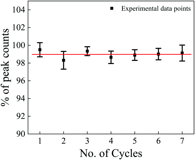 | ||
| Fig. 11 Reproducibility curve of the NaGdF4:3% Tb3+ phosphor irradiated with 10 kGy gamma rays. | ||
4.3 Experimental TL glow curve study
This method is useful for estimating the number and position of individual thermoluminescence (TL) peaks within a complex glow-curve. The experimental TL glow curve analysis is primarily the systematic thermal cleaning of TL peaks in the glow curve.51Tm–Tstop analysis and the Initial Rise Method (IRM) are among the important methods in the experimental glow curve study for the estimation of trapping parameters. The Tm–Tstop curves allow the individual peaks, i.e., the numbers of glow peak components in the complex glow curve of the phosphor, to be identified and the results are used as input parameters and thus can be analysed by the curve-fitting GCD procedure. In the present study, we used the NaGdF4:3% Tb3+ phosphor irradiated with a 10 kGy dose of gamma rays. In the Tm–Tstop analysis, first, we heated the phosphor material at a uniform heating rate of 5 °C from room temperature to the chosen temperature (Tstop). After heating, the phosphor sample was allowed to rapidly cool to room temperature and was again reheated to the next temperature (Tstop) in steps of 5 °C. This process was repeated for different values of Tstop (50, 55, 60… to …390, 395, 400 °C) through the entire glow curve, and the position of the peak temperature Tm (temperature corresponding to maximum intensity for the particular Tstop value) was noted; i.e., the cycle of heating, recording, cooling, and again heating was carried out up to the final temperature of 400 °C. In this process, we obtained a single TL curve for each Tstop value from which the Tm value was recorded and then a graph of Tm as a function of Tstop was plotted. A stepwise curve was obtained as shown in the inset image of Fig. 12, which was useful in determining the activation energy for each TL curve. The IRM method was subsequently employed. According to the IRM method, at the beginning of the TL glow peak, the concentration of trapped electrons changes only by a small amount with temperature, so that the first- and general-order TL equations are simplified as I(T) ∝ A![[thin space (1/6-em)]](https://www.rsc.org/images/entities/i_char_2009.gif) exp(−E/kT), where A is a constant, I(T) = TL intensity, T = absolute temperature, k = Boltzmann's factor and E = trap depth, and the TL intensity is independent of the order of kinetics. A plot of ln(I) versus 1/T would yield a straight line with a slope of −E/kT, from which the activation energy (E) can be determined.51–54 We plotted the slope of the straight line (ln(I) vs. 1/T) with each heating step interval of 5 °C to obtain the activation energy.46,55 The activation energies thus found were then plotted against the temperature to which the sample was heated, which often resulted in the “staircase”-shaped E–T curve as shown in Fig. 12. Each plateau region in the staircase corresponds to the approximate position/trapping state and the activation energy of an individual peak.51,55Fig. 12 illustrates the five TL trapping levels with the first plateau region observed in the temperature range of 80 to 105 °C, corresponding to the trap depth/activation energy of ∼1.10 eV. Similarly, the second to fifth plateau regions were found in the range of 130 to 155 °C, 175 to 210 °C, 240 to 270 °C, and 310 to 360 °C corresponding to trap depth/activation energies of ∼1.28 eV, ∼1.39 eV, ∼1.66 eV, and ∼1.60 eV, respectively. The trap depth or activation energy, E (eV) is the thermal energy required to release the trapped electrons and holes from their respective trap centers. These activation energies in the phosphor material indicate shallow and deeper trap levels within the band gap of the phosphor material. The value of E (eV) is high for releasing electrons from deep trapping sites and is low for releasing electrons from shallow trapping sites. If the value of the activation energy (E) is high, the glow peak occurs at a relatively higher trap and the corresponding trap created is stable, resulting in minimal fading of the corresponding TL glow peak and vice versa. As can be clearly seen from Fig. 12, five plateaus were found, which suggests that the TL glow curve overlapped with five glow peaks. The overlapped peaks can be separated and consequently, the trap parameters of each peak can be determined by using the glow curve deconvolution (GCD) method.
exp(−E/kT), where A is a constant, I(T) = TL intensity, T = absolute temperature, k = Boltzmann's factor and E = trap depth, and the TL intensity is independent of the order of kinetics. A plot of ln(I) versus 1/T would yield a straight line with a slope of −E/kT, from which the activation energy (E) can be determined.51–54 We plotted the slope of the straight line (ln(I) vs. 1/T) with each heating step interval of 5 °C to obtain the activation energy.46,55 The activation energies thus found were then plotted against the temperature to which the sample was heated, which often resulted in the “staircase”-shaped E–T curve as shown in Fig. 12. Each plateau region in the staircase corresponds to the approximate position/trapping state and the activation energy of an individual peak.51,55Fig. 12 illustrates the five TL trapping levels with the first plateau region observed in the temperature range of 80 to 105 °C, corresponding to the trap depth/activation energy of ∼1.10 eV. Similarly, the second to fifth plateau regions were found in the range of 130 to 155 °C, 175 to 210 °C, 240 to 270 °C, and 310 to 360 °C corresponding to trap depth/activation energies of ∼1.28 eV, ∼1.39 eV, ∼1.66 eV, and ∼1.60 eV, respectively. The trap depth or activation energy, E (eV) is the thermal energy required to release the trapped electrons and holes from their respective trap centers. These activation energies in the phosphor material indicate shallow and deeper trap levels within the band gap of the phosphor material. The value of E (eV) is high for releasing electrons from deep trapping sites and is low for releasing electrons from shallow trapping sites. If the value of the activation energy (E) is high, the glow peak occurs at a relatively higher trap and the corresponding trap created is stable, resulting in minimal fading of the corresponding TL glow peak and vice versa. As can be clearly seen from Fig. 12, five plateaus were found, which suggests that the TL glow curve overlapped with five glow peaks. The overlapped peaks can be separated and consequently, the trap parameters of each peak can be determined by using the glow curve deconvolution (GCD) method.
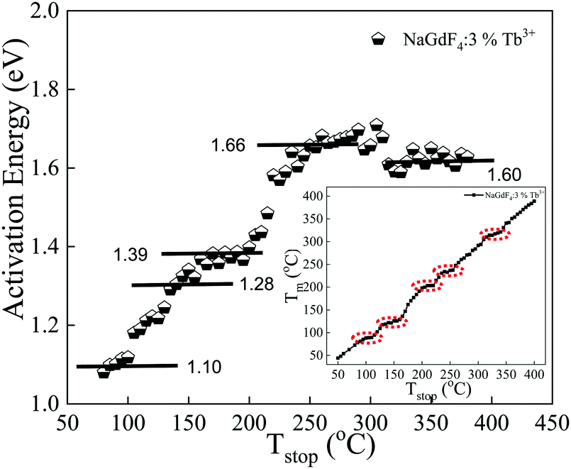 | ||
| Fig. 12 Activation energy (eV) vs. Tstop (°C) plot resulting from the IR method after the Tm–Tstop procedure for the NaGdF4:3% Tb3+ phosphor irradiated with gamma radiation of 10 kGy doses. A plot of Tm as a function of Tstop for the NaGdF4:3% Tb3+ phosphor as an inset image. | ||
4.4 Glow curve deconvolution (GCD) for dosimetric parameter evaluation
The glow curve is characteristic of the different trap levels that lie within the band gap of the phosphor material. Thus, to characterize the TL thermograms, it is necessary to evaluate their trapping parameters and the analysis of these trap levels is useful for estimating the localized trap depth. The dosimetric characteristics of the phosphor mainly depend on the kinetic parameters. Deconvolution of TL glow curves is a common tool for the analysis of TL glow curves and thus, the characterization of the nature of traps. This method is used to evaluate TL kinetics parameters that include trap depth (E), frequency factor (s), and order of kinetics (b) for a given peak in the glow-curve. These parameters reveal the stability of traps/luminescent centers. The trap depth or the thermal activation energy (E) is the energy needed to free the trapped electrons. The frequency factor conveys the value in the order of the lattice vibration frequency and the order of kinetics gives the information about whether or not the re-trapping of trapped charge carriers took place upon heating.56,57 TL glow curve deconvolution (GCD) is a very well-known method for analyzing the complex TL mechanism, which includes multiple peak glow curves. After the irradiation of the phosphor material, ionization takes place and electrons get trapped in the different trapping levels. During the TL process, traps recombine and this process depends on many factors such as the rate of temperature change, the thermal release of electrons from traps, escape frequency factor, re-trapping probabilities, etc. Thus, to determine the associated overlapping peak within the glow curve and to estimate the corresponding trapping parameters E, b and s, the obtained glow curves were de-convoluted using a glow curve de-convolution Excel spreadsheet program.58Fig. 13 represents the deconvoluted graph for the NaGdF4:3% Tb3+ phosphor annealed at 700 °C irradiated with a 10 kGy gamma dose. In the glow curve deconvolution analysis, we determined trapping parameters of the glow curve such as trap depth (E), frequency factor (s), order of kinetics (b), and figure of merit (FOM), with the accurate fitting of multiple glow peaks using Kitis equations.59 Depending on the shape of the glow peak, the probability of the de-trapping and re-trapping glow peaks is divided into three types, i.e., first-order, second-order, and general-order kinetics. In the present study, general-order kinetics were used; the equation is as follows: | (1) |
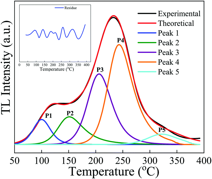 | ||
| Fig. 13 The deconvoluted glow curves of the NaGdF4:3% Tb3+ phosphor recorded after irradiation with a dose of 10 kGy gamma rays using the GCD program. | ||
Similarly, the frequency factor, i.e., the attempt to escape the frequency is give as
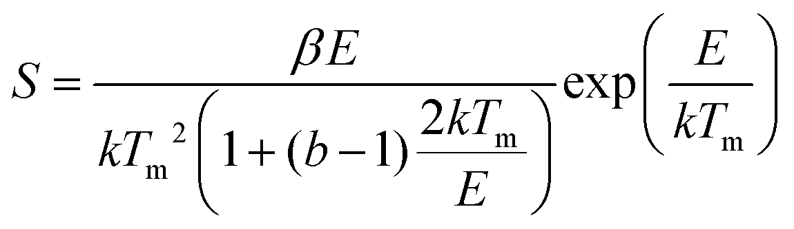 | (2) |
The peak was then generated theoretically using these parameters and was separated from the main experimental glow curve. The calculated kinetics (trapping) parameters for the NaGdF4:3% Tb3+ phosphor are summarized in Table 2, which convey that the trap depth of the phosphor increases with increasing temperature. The value of the activation energy varied from 1.0 eV to 1.66 eV; i.e., these peaks were formed at comparably deeper sites within the band gap of the phosphor, which illustrates the trapping of electrons in deep trap centers with appreciable trap depth in the TL process. The maximum error for the experimental and theoretical curves is approximately ±0.03%. The figure of merit (FOM), which is an important tool for checking the performance or accuracy of fitting between experimental data and theoretical data, was found to be only 2.2%, which indicates that the fit was successful and that revealed the accurate fitting of 5 different peaks within the glow curve as shown in Fig. 13. These results indicate that the experimental and theoretical curves are in good agreement and overlap each other.
| Sample name | Peaks | Temperature (Tm) | Order of kinetics (b) | Trap depth (eV) | Frequency factor (s−1) | FOM (%) |
|---|---|---|---|---|---|---|
| NaGdF4:3% Tb3+ | 1 | 100 | 1.9 | 1.0 ± 0.04 | 7.26 × 10¹⁴ | 2.2% |
| 2 | 152 | 1.97 | 1.25 ± 0.03 | 1.49 × 10¹⁶ | ||
| 3 | 205 | 1.9 | 1.39 ± 0.04 | 8.54 × 10¹⁵ | ||
| 4 | 243 | 1.35 | 1.66 ± 0.03 | 3.15 × 10¹⁶ | ||
| 5 | 322 | 2 | 1.60 ± 0.02 | 5.01 × 10¹⁴ |
The trapping parameters resulting from the experimental Tm–Tstop study followed by the activation energy vs. Tstop analysis and the theoretical glow curve deconvolution (GCD) match closely and are in good agreement with each other.
5. Conclusion
In summary, hexagonal phase monodispersed β-NaGdF4:x% Tb3+ (x = 0, 0.5, 1, 2, 3, 4, 5) spherical-shaped phosphor crystals were synthesized via a tri-sodium citrate-assisted hydrothermal method. Under UV excitation (λex = 228 nm), the β-NaGdF4:x% Tb3+ phosphor emitted strong green emission corresponding to 5D4 → 7FJ (J = 6, 5, 4, 3) transitions characteristic of Tb3+ ions. The as-prepared samples were annealed at different temperatures (200–800 °C) and the effect of thermal treatment on their structural, morphological, photoluminescence and thermoluminescence properties were studied. At the annealing temperature of 700 °C, XRD peaks of the cubic phase appeared; thus, at higher annealing temperature, the XRD pattern revealed a mixed phase of the cubic and hexagonal phases of the NaGdF4 phosphor. The NaGdF4 crystals fused into each other and agglomerated, giving rise to an irregular block-like morphology. The photoluminescence intensity was enhanced with thermal treatment due to the reduction in non-radiative processes from the surface and the volatilization of luminescence quenching (–OH) groups. Thermoluminescence studies were performed by irradiating the phosphor material with gamma-rays. Optimization of the TL properties revealed that the best dosimetric glow curve for NaGdF4:3% Tb3+ annealed at 700 °C peaked at 230 °C, signifying deeper traps. The NaGdF4:3% Tb3+ phosphor showed a linear response over a very wide range of gamma doses from 100 Gy to 20 kGy, then after saturation occurred. The low fading, less than ∼10% fading over the period of 90 days, reasonable reproducibility and a wide linear response range at a higher dose make this phosphor suitable for dosimetry for higher doses and imply excellent dosimetric properties. The Tm–Tstop method revealed five activation plateaus at 1.10 eV, 1.28 eV, 1.39 eV, 1.66 eV and 1.60 eV, which present the main contributions for radiation storage. The trapping parameters of trap depth (activation energy), the order of kinetics, and frequency factors were established by the Glow Curve Deconvolution (GCD) method. The trapping parameters resulting from the experimental Tm–Tstop study and theoretical GCD matched very well and are in good agreement with each other. To the best of our knowledge, for the first time, we have studied the thermoluminescence dosimetric properties of terbium ion-doped NaGdF4 phosphors. Apart from their unique strong photoluminescence properties and expected magnetic properties, which provide the NaGdF4:Tb3+ phosphor with the potential for application in color displays, LEDs, bimodal bioprobes, drug delivery, etc., the thermoluminescence properties of the NaGdF4:Tb3+ phosphor have been newly explored for potential new applications in the field of radiation dosimetry.Conflicts of interest
There are no conflicts of interest to declare.Acknowledgements
Preeti Padhye Kulkarni acknowledges the support from the Council of Industrial and Scientific Research (CSIR), India, grant/file No: 09/137(0598)/2019-EMR-I for financial assistance by providing the Research Associate Fellowship. One of the authors, Dr Mahesh Bhadane, is grateful to the Principal and management of the Rayat Shikshan Sanstha's Dada Patil Mahavidyalaya, Karjat, for the encouragement and help time to time. One of the Authors K. H. Gavhane is thankful to Chhatrapati Shahu Maharaj Research Training and Human Development Institute (SARTHI), Pune, for awarding CMSRF and financial assistance.References
- Thermoluminescent materials, ed. D. R. Vij, PTR Prentice Hall, New Jersey, 1993 Search PubMed.
- B. C. Bhatt and M. S. Kulkarni, Defect Diffus. Forum, 2014, 347, 179–227 Search PubMed.
- D. J. Daniel, O. Annalakshmi, U. Madhusoodanan and P. Ramasamy, J. Rare Earths, 2014, 32, 496–500 CrossRef CAS.
- N. Salah, S. S. Habib, Z. H. Khan, S. Al-Hamedi and S. P. Lochab, J. Lumin., 2009, 129, 192–196 CrossRef CAS.
- M. T. Jose, S. R. Anishia, O. Annalakshmi and V. Ramasamy, Radiat. Meas., 2011, 46, 1026–1032 CrossRef CAS.
- V. Pagonis, G. Kitis and C. Furetta, Numerical and Practical Exercises in Thermoluminescence, Springer Newyork, NY, 2006 Search PubMed.
- R. Chen and S. W. S. McKeever, Theory of Thermoluminescence and Related Phenomenon, World Scientific, 1997 Search PubMed.
- P. J. Fox, R. A. Akber and J. R. Prescott, J. Phys. D: Appl. Phys., 1988, 21, 189–193 CrossRef CAS.
- M. S. Bhadane, K. H. Gavhane, P. Kulkarni, S. S. Dahiwale, V. N. Bhoraskar, M. A. More, P. S. Patil and S. D. Dhole, J. Lumin., 2020, 223, 117168 CrossRef CAS.
- A. Duragkar, A. Muley, N. R. Pawar, V. Chopra, N. S. Dhoble, O. P. Chimankar and S. J. Dhoble, Luminescence, 2019, 34, 656–665 CrossRef PubMed.
- L. Gao, X. Ge, Z. Chai, G. Xu, X. Wang and C. Wang, Nano Res., 2009, 2, 565–574 CrossRef CAS.
- S. Zeng, G. Ren, C. Xu and Q. Yang, CrystEngComm, 2011, 13, 1384–1390 RSC.
- P. Padhye, S. Sadhu, M. Malik and P. Poddar, RSC Adv., 2016, 6, 53504–53518 RSC.
- P. Padhye, A. Alam, S. Ghorai, S. Chattopadhyay and P. Poddar, Nanoscale, 2015, 7, 19501–19518 RSC.
- J. Zhang, B. Li, L. Zhang and H. Jiang, Chem. Commun., 2012, 48, 4860–4862 RSC.
- J. M. Meruga, W. M. Cross, P. S. May, Q. Luu, G. A. Crawford and J. J. Kellar, Nanotechnology, 2012, 23, 395201 CrossRef PubMed.
- M. H. V. Werts, Sci. Prog., 2005, 88, 101–131 CrossRef CAS PubMed.
- Y. Wang, Y. Liu, Q. Xiao, H. Zhu, R. Lia and X. Chen, Nanoscale, 2011, 3, 3164–3169 RSC.
- C. Sun, C. Carpenter, G. Pratx and L. Xing, Nanoscale Res. Lett., 2011, 6(24), 1–7 Search PubMed.
- J. Heine and K. Müller-Buschbaum, Chem. Soc. Rev., 2013, 42, 9232–9242 RSC.
- V. Sudarsan, F. C. J. M. van Veggel, R. A. Herring and M. Raudsepp, J. Mater. Chem., 2005, 15, 1332–1342 RSC.
- J. Senthilselvan, S. Thomas, L. Anbharasi, D. Sarkar, V. N. K. B. Adusumalli, S. A. Kumar, S. Yamini, M. Gunaseelan, J. Manonmani and V. Mahalingam, J. Mater. Sci.: Mater. Electron., 2019, 30, 20376–20392 CrossRef CAS.
- M. M. Lezhnina, T. Jüstel, H. Kätker, D. U. Wiechert and U. H. Kynast, Adv. Funct. Mater., 2006, 16, 935–942 CrossRef CAS.
- L. Tashi, M. Kumar, Z. ul Nisa, N. Nelofar and H. N. Sheikh, New J. Chem., 2020, 44, 1009–1020 RSC.
- M. Banski, A. Podhorodecki, J. Misiewicz, M. Afzaal, A. L. Abdelhady and P. O'Brien, J. Mater. Chem. C, 2013, 1, 801–807 RSC.
- Y. Liu, D. Tu, H. Zhu, R. Li, W. Luo and X. Chen, Adv. Mater., 2010, 22, 3266–3271 CrossRef CAS PubMed.
- A. K. Parchur, A. I. Prasad, A. A. Ansari, S. B. Raia and R. S. Ningthoujam, Dalton Trans., 2012, 41, 11032–11045 RSC.
- T. Samanta, S. Sarkar, V. N. K. B. Adusumallia, A. E. Praveen and V. Mahalingam, Dalton Trans., 2016, 45, 78–84 RSC.
- Y. Na, S. Yang and S. Lee, Desalination, 2014, 347, 34–42 CrossRef CAS.
- İ. Y. Elbeyli, Hydrometallurgy, 2015, 158, 19–26 CrossRef.
- C. Cheng, Y. Wen, X. Xu and H. Gu, J. Mater. Chem., 2009, 19, 8782–8788 RSC.
- A. T. M. A. Rahman, K. Vasilev and P. Majewski, J. Colloid Interface Sci., 2011, 354, 592–596 CrossRef PubMed.
- Y. Song, B. Shao, Y. Feng, W. Lü, G. Liu and H. You, Dalton Trans., 2016, 45, 9468–9476 RSC.
- K. Naveen Kumar, R. Padma, Y. C. Ratnakaram and M. Kang, RSC Adv., 2017, 7, 15084–15095 RSC.
- C. Li, Z. Quan, J. Yang, P. Yang and J. Lin, Inorg. Chem., 2007, 46, 6329–6337 CrossRef CAS PubMed.
- D. Yang, D. Chen, H. He, Q. Pan, Q. Xiao, J. Qiu and G. Dong, Sci. Rep., 2016, 6, 29871 CrossRef CAS PubMed.
- J. Song, G. Zhi, Y. Zhang and B. Mei, Nano-Micro Lett., 2011, 3, 73–78 CrossRef CAS.
- E. Sadeghi, M. Zahedifar and M. K. Shoushtari, Appl. Radiat. Isot., 2018, 136, 111–117 CrossRef CAS PubMed.
- W. F. Hornyak, R. Chen and A. Franklin, Phys. Rev. B: Condens. Matter Mater. Phys., 1992, 46, 8036–8049 CrossRef PubMed.
- S. W. S. Mckeever, Thermoluminescence of solids, Cambridge University Press, Cambridge, 1985 Search PubMed.
- M. Prokic, Nucl. Instrum. Methods, 1980, 175, 83–86 CrossRef CAS.
- H. Kondo, T. Hirai and S. Hashimoto, J. Lumin., 2003, 102–103, 727–732 CrossRef CAS.
- Q. Zhao, B. Shao, W. Lü, W. Lv, M. Jiao, L. Zhao and H. You, Dalton Trans., 2015, 44, 3745–3752 RSC.
- S. Han, X. Qin, Z. An, Y. Zhu, L. Liang, Y. Han, W. Huang and X. Liu, Nat. Commun., 2016, 7, 13059 CrossRef CAS PubMed.
- S. Mahajna and Y. S. Horowitz, J. Phys. D: Appl. Phys., 1997, 30, 2603–2619 CrossRef CAS.
- K. H. Gavhane, M. S. Bhadane, A. S. Bhoir, P. P. Kulkarni, B. J. Patil, V. N. Bhoraskar, S. D. Dhole and S. S. Dahiwale, J. Alloys Compd., 2019, 817, 152805 CrossRef.
- D. L. Monika, H. Nagabhushana, S. C. Sharma, B. M. Nagabhushana and R. Hari Krishna, Chem. Eng. J., 2014, 253, 155–164 CrossRef CAS.
- S. P. Lochab, P. D. Sahare, R. S. Chauhan, N. Salah, R. Ranjan and A. Pandey, J. Phys. D: Appl. Phys., 2007, 40, 1343–1350 CrossRef CAS.
- M. S. Bhadane, S. S. Dahiwale, K. R. Sature, B. J. Patil, N. T. Mandlik, V. N. Bhoraskar and S. D. Dhole, J. Alloys Compd., 2017, 695, 1918–1923 CrossRef CAS.
- C. Furetta, Handbook of Thermoluminescence, World Scientific Publishing Co. Pte. Ltd, Singapore, 1937 Search PubMed.
- S. W. S. Mckeever, Phys. Status Solidi A, 1980, 62, 331–340 CrossRef CAS.
- M. Gokce, K. F. Oguz, T. Karalı and M. Prokic, J. Phys. D: Appl. Phys., 2009, 42, 105412 CrossRef.
- O. Q. De Clercq, J. Du, P. F. Smet, J. J. Joos and D. Poelman, Phys. Chem. Chem. Phys., 2018, 20, 30455–30465 RSC.
- S. Akca, M. Oglakci, Z. G. Portakal, N. Kucuk, M. Bakr, M. Topaksu and N. Can, Radiat. Phys. Chem., 2019, 160, 105–111 CrossRef CAS.
- A. N. Yazici, R. Chen, S. Solak and Z. Yegingil, J. Phys. D: Appl. Phys., 2002, 35, 2526–2535 CrossRef CAS.
- R. K. Tamrakar, D. P. Bisen, I. P. Sahu and N. Brahme, J. Radiat. Res. Appl. Sci., 2014, 7, 417–429 CrossRef.
- A. J. J. Bos, Materials, 2017, 10, 1357 CrossRef PubMed.
- D. Afouxenidis, G. S. Polymeris, N. C. Tsirliganis and G. Kitis, Radiat. Prot. Dosim., 2012, 149, 363–370 CrossRef CAS PubMed.
- G. Kitis, J. M. Gomez-Ros and J. W. N. Tuyn, J. Phys. D: Appl. Phys., 1998, 31, 2636–2641 CrossRef CAS.
Footnote |
| † Electronic supplementary information (ESI) available. See DOI: 10.1039/d0ma00247j |
| This journal is © The Royal Society of Chemistry 2020 |