 Open Access Article
A porous organic polymer-coated permselective separator mitigating self-discharge of lithium–sulfur batteries†
Deepa Elizabeth
Mathew
ab,
Sivalingam
Gopi
ab,
Murugavel
Kathiresan
 *ab,
G. Jenita
Rani
c,
Sabu
Thomas
 d and
A. Manuel
Stephan
 *ab
*ab
aCSIR-Central Electrochemical Research Institute, Karaikudi 630 003, India. E-mail: amstephan@cecri.res.in; kathiresan@cecri.res.in; Fax: +91 4565 27779; Tel: +91 4565 241426
bAcademy of Scientific and Innovative Research (AcSIR), CSIR-CECRI Campus, Karaikudi, India
cDepartment of Physics, Fatima College (Autonomous), Madurai 625 017, India
dInternational and Inter-University Centre for Nanoscience and Nanotechnology, Mahatma Gandhi University, Kottayam, 686560, India
First published on 21st May 2020
Abstract
Lithium–sulfur (Li–S) batteries are considered as futuristic energy storage systems owing to their high theoretical energy density, environmental benignity, and relatively low cost. However, their practical applications are still hampered by the insulating nature of elemental sulfur and the capacity degradation resulting from lithium polysulfide (LiPS) shuttling. Herein, we demonstrate the use of a porous organic polymer-coated Celgard 2320 (POP-CG) separator as the permselective membrane that is capable of not only delivering a higher discharge capacity but also preventing self-discharge of the Li–S cell up to 116 h which is superior compared to earlier reports. This coated membrane not only offers a higher discharge capacity but also exhibited superior wettability and thermal stability. The enhanced electrochemical properties of the lithium–sulfur cell are mainly attributed to the POP coated on the separator which effectively confines polysulfides via chemical interactions.
1. Introduction
Development of efficient electrical energy conversion and storage devices has become the most crucial concern of the twenty-first century in order to circumvent the issues associated with not only the use of fossil fuels but also increased demand from the electronic and transport sectors.1 Compared to the state-of-the-art lithium-ion batteries (LIBs), lithium–sulfur (Li–S) batteries have attracted much attention owing to their high specific capacity (1672 mA h g−1), non-toxicity, low cost, rich abundance of elemental sulfur and environmental friendliness.2 The conversion reaction of sulfur offers a high theoretical capacity by reversibly interacting two electrons per sulfur atom (Li2S). Despite its advantages, the Li–S system still suffers from several challenges that restrain it from practical applications.3The low electronic conductivity of elemental sulfur and the formation of soluble lithium polysulfide species during the discharge and charge mechanism result in low utilization of active materials and poor Coulombic efficiency.2,3 The polysulfide intermediates formed during discharge easily gets dissolved in the organic electrolyte. The diffusion of these polysulfide anions (Sx2−) to the anode causes a prodigious loss of active materials and leads to rapid capacity fading. The dissolved polysulfides in the organic electrolyte also give rise to many other problems including Li corrosion.4,5 The volume expansion (up to 80%) of the sulfur electrode leads to structural instability of the electrode. Additionally, the poor interfacial property of the lithium metal anode affects the capacity of the Li–S batteries. To exploit the full potential of this promising technology and to make it viable, these issues have to be addressed.6 The insulating nature of sulfur was addressed by incorporating various carbonaceous materials such as graphene, carbon nanotubes (CNTs), and carbon fibers (CNFs) with outstanding frame structures and good electrical conductivity. These carbonaceous materials have been introduced generally as matrix skeletons for sulfur cathodes not only to improve their electrochemical performance but also to control the volume expansion.7,8 However, the polysulfide shuttling between the cathode and the anode remains a crucial concern. Several strategies such as the introduction of glass-ceramic,9 solid polymer,10 and gel polymer electrolytes11 have been adopted in Li–S batteries to prevent polysulfide shuttling. Even though the polysulfide shuttling was appreciably reduced by the introduction of solid electrolytes, the lithium-ion diffusion rate through the electrolytes was found to be low which limited the rate capability of the Li–S cells.
Introduction of permselective membranes into the Li–S battery assembly has emerged as a powerful technique to retain polysulfides on the cathode side of the cell and thus to enhance the electrochemical performance. Multifunctional membrane separators with permselectivity or localizing abilities placed between the cathode and the anode play a crucial role not only in preventing electrical short circuit and transportation of the ions between the cathode and the anode, but also in suppressing the migration of polysulfides, increasing the reactivation of some species that contain dead sulfur, and preventing the formation of dendrites on the lithium anode surface.12–14 The use of several membrane designs based on various functional groups with negative surface charge as polysulfide blocking layers in Li–S batteries has been examined, amongst which Nafion,15 graphene oxide,16 and MOFs17 have received the most attention.
Very recently porous organic polymers (POPs) have attracted much attention due to their enormous potential design space offered by the atomically precise spatial assembly of molecular organic building blocks. The geometry and dimensions of the building blocks can be controlled to direct the topological evolution to create structural periodicity in the framework, hence make them designable for different applications such as gas storage,18,19 separation,20,21 catalysis,22 sensors23,24 and drug delivery.25,26 Liao and co-workers demonstrated that the CTF based on 1,4-dicyanobenzene is effective in trapping polysulfide via adsorption.27 Very recently Si and co-workers reported a composite ceramic permselective membrane prepared by the polymerization of 2,5-dimethoxy-1,4-dicarboxaldehyde and tetrakis(4-aminophenyl)ethane (DMTA-COF) to enhance the electrochemical performance of Li–S and Li–Se batteries by providing a strong sieving effect from the nanopores of DMTA-COF.28,29 A separator developed by direct coating modification of a commercial PP separator with functional rich amine porous organic polymer/acetylene black-polypropylene (RAPOP/AB-PP) improved the electrochemical performance of Li–S batteries.30 POPs based on covalent triazine linkages are highly conjugated and assist electron transport as well as confinement of polysulfides in their nanopores via chemical interactions between triazine ‘N’ and the formed sulfur species, thereby improving the cycling performance.31 Since POPs exhibit varying porosity, physical confinement of polysulfides is possible apart from chemical confinement via various interactions.
Herein, we propose the use of a phenylenediamine based POP coated permselective separator for Li–S batteries. In the present work, the materials used for the preparation of POP are facile and inexpensive. It is expected that the secondary amine groups on POP offer Lewis basicity and, in addition, triazine ‘N’ along with secondary amine groups on the POP can interact with the Li+-ion (via electrostatic attraction as well as Lewis acid–base interactions). Altogether, the triazine linkages in the network facilitate chemical interactions with the Li+-ion (via electrostatic attraction) and the polysulfide anion (via electrostatic repulsion). The nanopores of POP are expected to further confine polysulfides physically, i.e., there will be a sieving effect that confines polysulfide migration to the other side.31 Synergistically the combined interactions (physical as well as chemical interactions) will efficiently act as a permselective separator in confining lithium polysulfides from shuttling, thereby mitigating the self-discharge of Li–S batteries.
2. Experimental
2.1 Synthesis of triazine-phenylenediamine-porous organic polymer (TP-POP)
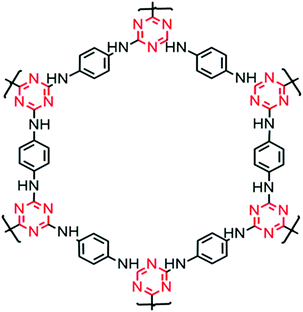
TP-POP was synthesized as reported earlier.32Fig. 1 shows the structure of TP-POP prepared from the nucleophilic substitution reaction of cyanuric chloride with 1,4-phenylenediamine in the presence of a base. The as prepared POP sample was then characterized by 1H, 13C and 15N NMR, and the obtained results are in accordance with earlier reports and are given as ESI† (Fig. S1a–c).33,34 The powder XRD analysis of the TP-POP sample revealed an amorphous nature and BET surface area analyses were also carried out. For the sake of data completion, the results are provided in the ESI† (Fig. S1d and e).2.2 Modification of the separator
The POP coated permselective membrane was prepared by the phase inversion method as reported elsewhere.35 A combination of solvents N-methyl pyrrolidone (7 g) and acetone (6 g) was used to dissolve poly(vinylidene fluoride) (PVdF) as a binder (20 wt%). To the resultant viscous solution, 80% of POP was slowly added, and the mixture was stirred for about 10 h in order to obtain a homogeneous slurry. The highly viscous slurry was subsequently coated on a commercial Celgard (2320) membrane. The coated separator was finally dried for 1 h at 40 °C. The prepared membrane was exposed to steam from purified boiling water for 15 min in order to enable phase inversion.35 After the phase inversion treatment, the coated membrane was dried in a vacuum oven for 24 h at 70 °C for further characterization. The areal loading of POP on the Celgard membrane was 2 mg cm−2.The composite sulfur cathode was prepared by mixing the sulfur composite (rGO–MnFe2O4 (MFO)–sulfur), Super P carbon and poly(vinylidene fluoride) in the mass ratio of 72![[thin space (1/6-em)]](https://www.rsc.org/images/entities/char_2009.gif) :
:![[thin space (1/6-em)]](https://www.rsc.org/images/entities/char_2009.gif) 16
16![[thin space (1/6-em)]](https://www.rsc.org/images/entities/char_2009.gif) :
:![[thin space (1/6-em)]](https://www.rsc.org/images/entities/char_2009.gif) 12 dispersed in N-methyl-2-pyrrolidone. The sulfur composite was prepared as reported elsewhere.36 The obtained highly viscous slurry was then coated on aluminium foil and the foil was dried in an air oven at 70 °C. The electrode was then dried in a vacuum glass oven at 110 °C for 6 hours prior to cell assembly.
12 dispersed in N-methyl-2-pyrrolidone. The sulfur composite was prepared as reported elsewhere.36 The obtained highly viscous slurry was then coated on aluminium foil and the foil was dried in an air oven at 70 °C. The electrode was then dried in a vacuum glass oven at 110 °C for 6 hours prior to cell assembly.
2.3 Material characterization
In order to analyse the influence of POP on the charge–discharge properties of Li-S cells both uncoated and coated membranes were subjected to physical and electrochemical analyses. The apparent contact angle (Data Physics OCA35, Germany) measurements were made for the 2320 type Celgard (CG 2320) and POP coated permselective membrane (POP-CG) surfaces with a non-aqueous liquid electrolyte. Tensile measurements (Tinius Olsen, H5KT) were also performed to estimate the mechanical integrity of the membrane. The ionic conductivity of the CG and permselective membranes at 25 °C was measured using an electrochemical impedance analyser (VSP-Biologic Science Instruments) with an AC sine wave perturbation of 10 mV in the frequency range between 1 MHz and 50 mHz by sandwiching the membranes between stainless steel blocking electrodes of 1.0 cm diameter.37 The statistical error analysis was performed for some of the experiments four times (e.g. contact angle, self-discharge, tensile and dimensional stability) to confirm the reproducibility of the results.2.4 Assembly of 2032-type coin cells
2032-type coin cells were assembled with the rGO–MFO–S cathode of 57 μm thickness and 14 mm diameter with an aerial sulfur loading of 2.47 mg cm−2 and a lithium metal foil (Sigma-Aldrich) of 14 mm diameter and 0.75 mm thickness. The composite sulfur cathode was composed of rGO/MFO/S in the ratio of 10![[thin space (1/6-em)]](https://www.rsc.org/images/entities/char_2009.gif) :
:![[thin space (1/6-em)]](https://www.rsc.org/images/entities/char_2009.gif) 10
10![[thin space (1/6-em)]](https://www.rsc.org/images/entities/char_2009.gif) :
:![[thin space (1/6-em)]](https://www.rsc.org/images/entities/char_2009.gif) 80. The electrolyte to electrode (sulfur content) ratio was 20 μL mg(sulfur)−1. The non-aqueous liquid electrolyte containing 1 M LiN(CF3SO2)2 and 0.05 M LiNO3 in a 1
80. The electrolyte to electrode (sulfur content) ratio was 20 μL mg(sulfur)−1. The non-aqueous liquid electrolyte containing 1 M LiN(CF3SO2)2 and 0.05 M LiNO3 in a 1![[thin space (1/6-em)]](https://www.rsc.org/images/entities/char_2009.gif) :
:![[thin space (1/6-em)]](https://www.rsc.org/images/entities/char_2009.gif) 1 (v/v) ratio of 1,3-dioxolane and tetra ethylene glycol dimethyl ether (TEG DME) mixture was used in an argon-filled glove box (M Braun, Germany). The electrochemical performance of the Li–S cells was then investigated by cyclic voltammetry, charge–discharge, and electrochemical impedance spectroscopic measurements.
1 (v/v) ratio of 1,3-dioxolane and tetra ethylene glycol dimethyl ether (TEG DME) mixture was used in an argon-filled glove box (M Braun, Germany). The electrochemical performance of the Li–S cells was then investigated by cyclic voltammetry, charge–discharge, and electrochemical impedance spectroscopic measurements.
The lithium-ion diffusion coefficient DLi+ was calculated from cyclic voltammetry measurements according to the Randles–Sevcik equation:38
| Ip = 2.69 × 10⁵·n1.5·A·DLi+0.5·CLiν0.5 | (1) |
The electrochemical impedance spectroscopy (EIS) measurements were carried out (Biologic, France) before and after cycling between 1 MHz and 50 mHz. The cycled cells were disassembled in an argon-filled glove box very carefully in order to carry out the post cycling analysis. The XPS analysis of the permselective membrane (Thermo Scientific, USA) was made after 100 cycles between 100 and 600 eV.
3. Results and discussion
3.1 Physical characterization
Fig. 2a–d, respectively, show the digital photograph, apparent contact angle measurements for CG 2320 and POP-CG and the cross-sectional image of the coated membrane. The coated membrane was flexible and robust. Particles also showed good gluing property with the 2320 Celgard membrane. The apparent contact angle measurements depict the surface wettability property of a membrane.42,43 As illustrated in Fig. 2b and c, the apparent contact angles of CG 2320 and POP-CG were observed to be 42.3° and 20.2°, respectively. In the present study, we observed Wenzel type of wetting.42,43 The POP coated membrane thus offered better wettability compared with the 2320 Celgard membrane, which is ascribed to the affinity of the nonaqueous electrolyte with the membrane. The POP was uniformly coated over the 2320-type Celgard membrane and the thickness of the coated membrane was 7.17 μm (Fig. 2d). | ||
| Fig. 2 (a) Digital photograph of the POP coated 2320-type Celgard membrane, contact angle shots of (b) CG 2320 and (c) POP-CG and (d) the cross-sectional SEM image of the POP coated Celgard membrane. | ||
The digital photograph of the POP-coated Celgard membrane (Fig. 2a) shows that the membrane is very flexible, the coated material was found to be stable, and no delamination of POP from the surface of the Celgard was observed. Furthermore, to confirm the thermal stability of the membrane, both CG 2320 and POP-CG membranes were stored in an oven at 125° for one hour. The uncoated Celgard membrane was rolled off while the POP-CG membrane was dimensionally stable (Fig. S2a and b, ESI†). The mechanical properties of CG 2320 and POP-CG were analysed using stress–strain measurements and are presented in Fig. S2(c) (ESI†). Both the samples show linear elastic behaviour followed by plastic deformation. It is clear from the stress–strain plots that the POP coating on the CG influenced the behaviour of the samples towards an applied strain. The tensile strength of CG 2320 was found to be 132 MPa with an elongation at break of 93.7%. The incorporation of POP coating in the CG 2320 enhanced its tensile strength. The POP-CG showed an ultimate tensile strength of 187 MPa with a higher Young's modulus compared with CG 2320. However, the elongation at break (the measure of flexibility) of the POP-coated CG sample was found to be 63% (slightly lower than that of CG 2320) which is sufficient from the real application point of view (Fig. S2, ESI†).
3.2 Electrochemical characterization
The ionic conductivity values of the Celgard and permselective membranes at room temperature, 25 °C, were found to be 4.9 × 10⁻⁴ and 5.6 × 10⁻⁴ S cm−1, respectively. The enhanced ionic conductivity observed for the POP-CG membrane is attributed to the high surface area offered by the POP; the POP-CG membrane offers higher uptake (better wettability) of the electrolyte compared with CG 2320 and hence facilitates marginally improved Li+-ion mass transfer.The electrochemical performance of the Li–S cells with uncoated CG 2320 and POP-coated membranes was then investigated by cyclic voltammetry. Fig. 3a and b demonstrate that the cyclic voltammograms of Li–S cells show two reduction and two oxidation peaks irrespective of the uncoated/coated CG membranes used. Two reduction peaks that appear around 2.36 and 1.93 V correspond to the solid–liquid two-phase electrochemical reduction of the crown-like octa sulfur ring into soluble higher-order lithium polysulfides Li2Sx (4 < x ≤ 8) and the further liquid–solid two-phase reduction of dissolved lithium polysulfides into insoluble lower-order polysulfides (Li2S2 and Li2S).44 During the following charge, two oxidation peaks were observed around 2.4 and 2.48 V and are attributed to the oxidation of solid Li2S2 and Li2S to soluble polysulfides and finally to elemental sulfur. It is worth mentioning that, unlike Li–S cells with the CG 2320 membrane, there was no discernible shift in the CV peaks in the subsequent cycles indicating that there was no polarization effect in the cell. Furthermore, the peaks of the Li–S cell with the POP-CG membrane were very sharp which indicates the fast kinetics of the system.
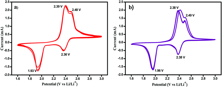 | ||
| Fig. 3 Cyclic voltammetry measurements of Li–S cells containing (a) uncoated CG 2320 and (b) POP-CG separator. | ||
The Randles–Sevcik equation was used to calculate the lithium-ion diffusion coefficient using the data obtained from cyclic voltammograms recorded at different scan rates, which are shown in Fig. S5 (ESI†). The lithium-ion diffusion coefficients were calculated using eqn (1) to be 4.9 × 10⁻¹¹, 8.1 × 10⁻¹¹, 6.7 × 10⁻¹⁰, and 1.29 × 10⁻⁹ cm2 s−1 for the uncoated and 9.6 × 10⁻¹¹, 1.05 × 10⁻¹⁰, 5.66 × 10⁻¹⁰, and 4.01 × 10⁻¹⁰ cm2 s−1 for the POP-coated membrane, respectively. The magnitude of lithium-ion diffusion values for the coated membrane was found to be higher compared with those measured for the uncoated separator.
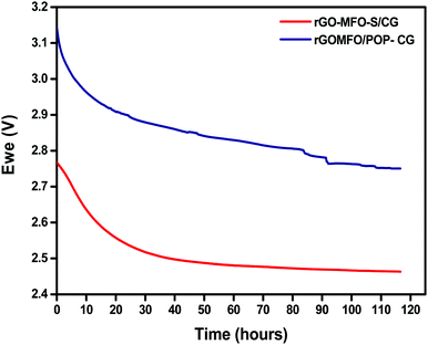
The lithium–sulfur system suffers from self-discharge and is considered as a major challenge due to the internal redox polysulfide shuttling. Soluble higher-order polysulfides will get dissolved in the electrolyte and, due to the concentration gradient, will migrate to the anode side and then react with metallic lithium. This results in open-circuit voltage drop and loss of discharge capacity and therefore it remains unsuitable for commercialization.40 The open-circuit potential (OCV) of lithium–sulfur cells with CG and POP-CG was measured as a function of time in order to evaluate the performance of permselective membranes as depicted in Fig. 4. The OCV of Li–S cells with the CG and the POP-CG was observed for almost 116 h. The Li–S cell with the CG showed an OCV of 2.76 V after the cell assembly, which gradually decreased and became stable at 2.46 V at 80 h. On the contrary, the cell voltage was exceptionally maintained at 2.76 V even after 116 h by POP-CG with a stable OCV which indicates that the spontaneous formation and subsequent shuttling of PS were suppressed by POP.
The shuttle current measurement and its change with time will give valuable insights into the factors influencing polysulfide shuttling in a lithium–sulfur cell. The concentration of polysulfide species at the cathode was determined by the chosen value of constant electrode potential. The negative current corresponds to the reduction of polysulfide species at the cathode while the positive current indicates the oxidation of the polysulfide species (e.g. S42− and S62−) at the cathode required to maintain the flux due to the shuttle process.41 The steady-state current is equal to the steady rate of oxidation of soluble polysulfide species required to maintain the concentration at the cathode at 2.3 V.
Most commonly, a linear decay in shuttle current is observed for lithium–sulfur cells and the rate of decay in shuttle current is correlated to the amount of higher-order polysulfides converted to insoluble lower-order polysulfides at the lithium-metal anode side. Hence, lesser amount of deposition of insoluble polysulfide on anode is expected to offer better capacity retention of Li–S cell. The current profile was observed when the cell was maintained at a constant potential of 2.3 V as shown in Fig. S3 (ESI†) which reveals that the POP-coated membrane caused the least decay in current with time, as compared to the separator with the uncoated one, and indicates an effective suppression of polysulfide shuttling by the POP-coated membrane. The insoluble lower-order polysulfides such as S22− can disproportionately to a small extent produce some higher-order soluble polysulfides S42− which increases the concentration of S42− at the cathode and thus the electrode potential becomes more positive.
Interestingly, it is obvious from the results that an enormous amount of higher-order polysulfides are converted into lower-order polysulfides at the anode for the lithium–sulfur cell with the uncoated Celgard membrane.12,13 Fig. S4a–c (ESI†) show the SEM images of Celgard 2320 and POP-coated CG before and after cycling, respectively. It can be seen that the highly porous surface of the POP-coated membrane becomes agglomerated due to the deposition of polysulfides upon cycling.
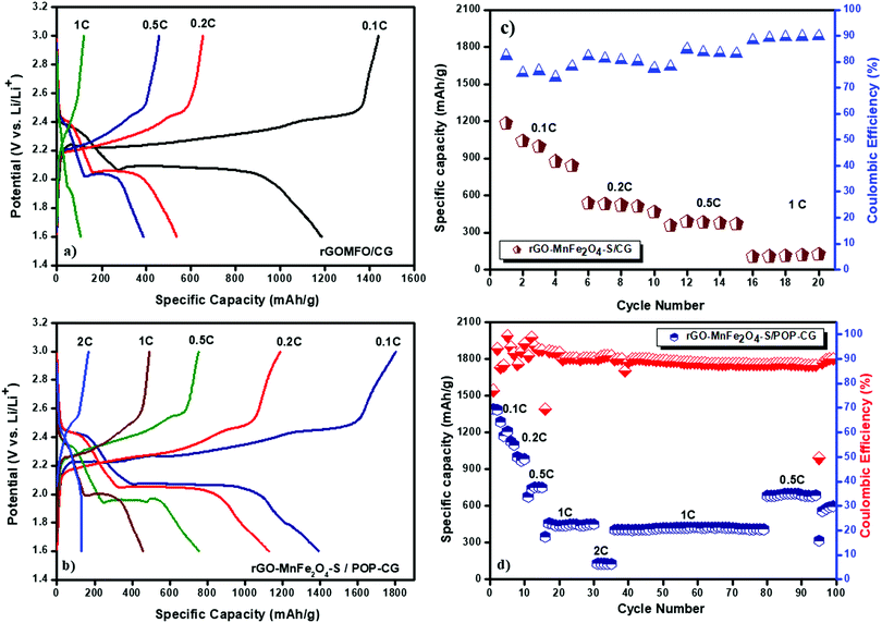
Fig. 5a and b, respectively, illustrate the initial galvanostatic charge–discharge profiles of Li–S cells with CG 2320 and POP-coated CG separators at different C-rates. Apparently, in both cases, the plateaus of charge–discharge processes closely match with the anodic and cathodic peak positions of cyclic voltammetry curves. The first plateau in the discharge profile at 2.43 V corresponds to the reduction of S8 to higher-order Li2Sx (4 − x − 8), while the second plateau 2.07 V represents the transformation of higher-order polysulfides to lower-order Li2S2/Li2S. Appreciably, the Li–S cell with POP-coated Celgard 2320 exhibited lower voltage hysteresis (0.20 V) compared with the uncoated CG (0.21 V). The lower value of voltage hysteresis for Li–S cells with the POP-coated Celgard membrane is attributed to the low polarization of the POP coated on the separator. Although the cell with the CG 2320 separator delivered a discharge capacity of 1184 mA h g−1, which corresponds to 80% utilization of sulfur, its discharge capacity is drastically reduced to 840 mA h g−1 during its 5th cycle. This exponential decrease in capacity is attributed to the polysulfide shuttling phenomenon, which originates from the migration of higher-order polysulfides through the pores of the CG membrane towards the lithium metal anode.
The discharge capacities of the Li–S cell with the POP-CG membrane are found to be 1390, 1126, 754 and 457 mA h g−1 at C-rates of 0.1, 0.2, 0.5 and 1, respectively. The discharge capacity of the POP-CG membrane separator cell decreased from 1390 to 1126 mA h g−1 when the current density is increased from 0.1C to 0.2C. Upon completion of 80 cycles the cell was again cycled at 0.5C indicating that the cell is capable of recovering its original capacity at 0.5 and 0.2C and thus demonstrates excellent rate capability and capacity retention. It is quite obvious from Fig. 5c and d that the Li–S cells with POP-CG delivered higher discharge capacity and Coulombic efficiency compared with the cell with the CG separator. However, the cell with POP-CG offered the capacity retention of 79.2% calculated with respect to the initial cycle.
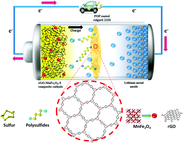
It is also evident from Fig. 5c and d that at lower current rates (0.1C and 0.2C) the discharge capacities of the Li–S cell with CG 2320 and POP-CG membranes decreased very drastically, which is ascribed to the dissolution of polysulfides in the electrolyte and subsequent diffusion and reaction with the lithium metal anode. The charging capacity vs. cycle number for Fig. 5d is shown in the ESI† (Fig. S6). Appreciably, at a C-rate of 1C (with a short charging and discharging time) the capacity fading was reduced and stable cyclability was achieved with 90% coulombic efficiency. The better cyclability with appreciable coulombic efficiency is attributed to the slower diffusion of polysulfides to the anode than to the total electrochemical reaction time. Generally, the measurement of coulombic efficiency is widely used to quantify the shuttle process. The measured values of coulombic efficiency may vary due to the rate of charge and discharge with a corresponding duration in the shuttle process.41 For example, the impact on the shuttle process is high for a Li–S cell at low rates. However, at high rates of charge and discharge, a high value of coulombic efficiency is observed and thus a comparison between the high and low rates becomes highly complicated.45–48 The higher initial discharge capacity is indicative of greater active material utilization in the Li–S cell with the POP-coated membrane. Therefore, it is further confirmed that the coated POP efficiently inhibits the migration of polysulfide and the reactivation of trapped polysulfides as illustrated schematically in Fig. 6. Although the coated separator shows an increased thickness and a reduced porosity by coated POP particles, higher electrolyte wettability was seen for the POP-coated Celgard separator (Fig. 1). This enhanced wettability of the POP-coated Celgard separator reduces the interfacial resistance and enhances the lithium-ion transport, which is essential to improve the overall electrochemical performance of Li–S batteries.
Electrochemical impedance spectroscopy (EIS) was used to analyse the influence of the permselective separator on the cycling performance of the Li–S cell with uncoated and POP-coated membranes by measuring the impedance before and after cycling and the spectra are, respectively, depicted in Fig. 7a and b. The inset figure shows the corresponding equivalent circuits. Rs, Rct, W and Cdl, respectively, represent the solution resistance, charge transfer resistance, Warburg impedance and double layer capacitance. Comparing the resistance values, the Li–S cell with the uncoated CG 2320 membrane exhibited higher solution resistance for ion transport compared with the cell with the POP-CG membrane. The solution resistance (Rs) and charge transfer resistance (Rct) values for the Li–S cell with uncoated and POP-coated membranes after 100 cycles were measured to be 4.0, 4.70 and 6.76, 18.4 Ohms respectively. The Li–S cell with the POP-CG membrane exhibited higher resistance values which are attributed to the resistance offered by the coated POP. It is worth mentioning that the value of Rct did not change much for the Li–S cell with the uncoated membrane. Unlike the usual increase of those with conventional sulfur electrodes, the Li–S cell with the POP-coated membrane exhibits a lower resistance value which is attributed to the prevention of the aggregation of Li2S on the cathode.47 Thus, the Li–S cell with the POP-CG membrane exhibited a low Rct value and this appreciable property qualifies it as a promising candidate for Li–S batteries.
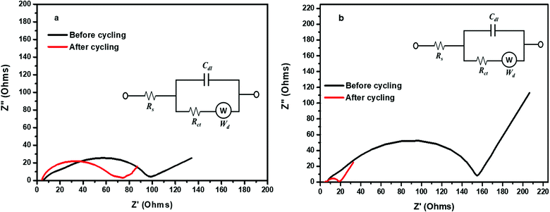 | ||
| Fig. 7 Electrochemical impedance spectra for the Li–S cell with (a) the uncoated membrane and (b) the POP coated membrane before and after cycling. Inset: The corresponding equivalent circuits. | ||
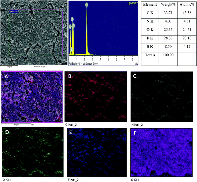
The POP-CG membrane was subjected to energy-dispersive X-ray spectroscopy (EDS) analysis after cycling and the results are depicted in Fig. 8. Panels 1–3 show the FESEM and elemental mapping analyses. The POP-CG membrane showed a slackly packed surface morphology (Fig. 8A) due to the deposition of polysulfides on its surface. The presence of C, N and O could be identified from Fig. 8B, C and D, respectively, which originate from the POP. Traces of fluorine (Fig. 8E) were identified owing to the presence of the binder (PVdF) used for coating the POP, which confirms the formation of LiF. The presence of sulfur (Fig. 8F) indicates the confinement of Li2S or Li2S2.
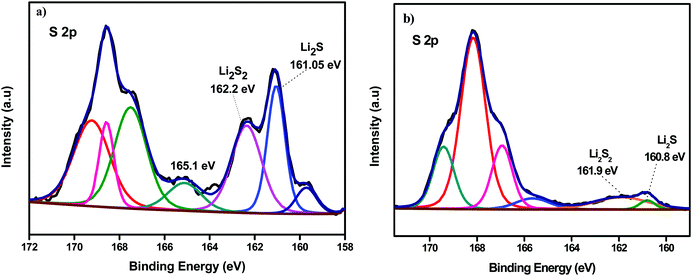
Fig. 9a and b, respectively, depict the deconvoluted S 2p peaks of the anodes removed from the Li–S cells containing the uncoated Celgard and POP-coated trilayer membrane after cycling. Apparently from both spectra detectable S–O species at binding energies above 165 eV are seen which can be attributed to the aerobic oxidation of S species upon disassembling the cell. Interestingly a lower amount of polysulfides (162.2 eV) and Li2S (161.05 eV) species at the anode dismantled from the cell that contained the coated separator.49 This further supports the proposed repulsion of polysulfide migration by the POP coated on the Celgard membrane.
4. Conclusions
In summary, POP was successfully synthesized and coated on a Celgard 2320 separator and used as a permselective membrane for Li–S batteries. This modified separator was found to confine polysulfide efficiently, leading to a high coulombic efficiency at higher C-rates with long cycling stability. Additionally, the coated POP on the Celgard membrane enhanced the thermal stability and wettability of the membrane which in turn increased the ionic conductivity of the membrane. The Li–S cell with the POP-CG separator delivered an excellent performance with a discharge capacity of 1390 mA h g−1 at 0.1C. This POP-CG not only mitigated the shuttling of polysulfides appreciably via chemical interactions but also suppressed the self-discharge of the lithium–sulfur cell up to 116 h. The present work provides further insight into the development of high-energy-density and durable Li–S batteries.Conflicts of interest
There are no conflicts to declare.Acknowledgements
The authors gratefully acknowledge the UGC, New Delhi for financial support.References
- B. C. Liu, F. Li, L. Ma and H. Cheng, Adv. Mater., 2010, 22, E28–E62 CrossRef PubMed.
- A. Manthiram, Y. Fu, S. Chung, C. Zu and Y. Su, Chem. Rev., 2014, 114, 11751–11787 CrossRef CAS PubMed.
- Y. Su, Acc. Chem. Res., 2013, 46, 1125–1134 CrossRef PubMed.
- D. Aurbach and Y. Gofer, J. Electrochem. Soc., 1991, 138, 3529–3536 CrossRef CAS.
- M. Arakawa, S. Ichi Tobishima, Y. Nemoto, M. Ichimura and J. Ichi Yamaki, J. Power Sources, 1993, 43, 27–35 CrossRef CAS.
- X. Gu and C. Lai, J. Mater. Res., 2018, 33, 16–31 CrossRef CAS.
- D. W. Wang, Q. Zeng, G. Zhou, L. Yin, F. Li, H. M. Cheng, I. R. Gentle and G. Q. M. Lu, J. Mater. Chem. A, 2013, 1, 9382–9394 RSC.
- Y. Ma, H. Zhang, B. Wu, M. Wang, X. Li and H. Zhang, Sci. Rep., 2015, 5, 1–10 CAS.
- L. Wang, Y. Zhao, M. L. Thomas, A. Dutta and H. R. Byon, ChemElectroChem, 2016, 3, 152–157 CrossRef CAS.
- D. Bresser, S. Passerini and B. Scrosati, Chem. Commun., 2013, 49, 10545–10562 RSC.
- H. S. Ryu, H. J. Ahn, K. W. Kim, J. H. Ahn and J. Y. Lee, J. Power Sources, 2006, 153, 360–364 CrossRef CAS.
- S. Suriyakumar, A. M. Stephan, N. Angulakshmi, M. H. Hassan and M. H. Alkordi, J. Mater. Chem. A, 2018, 6, 14623–14632 RSC.
- S. Suriyakumar, M. Kanagaraj, M. Kathiresan, N. Angulakshmi, S. Thomas and A. M. Stephan, Electrochim. Acta, 2018, 265, 151–159 CrossRef CAS.
- M. Raja, S. Suriyakumar, N. Angulakshmi and A. Manuel Stephan, Inorg. Chem. Front., 2017, 4, 1013–1021 RSC.
- J. Q. Huang, Q. Zhang, H. J. Peng, X. Y. Liu, W. Z. Qian and F. Wei, Energy Environ. Sci., 2014, 7, 347–353 RSC.
- T. Z. Zhuang, J. Q. Huang, H. J. Peng, L. Y. He, X. B. Cheng, C. M. Chen and Q. Zhang, Small, 2016, 12, 381–389 CrossRef CAS PubMed.
- S. Bai, X. Liu, K. Zhu, S. Wu and H. Zhou, Nat. Energy, 2016, 1, 16094 CrossRef CAS.
- H. Furukawa and O. M. Yaghi, J. Am. Chem. Soc., 2009, 131, 8875–8883 CrossRef CAS PubMed.
- S. H. Sang, H. Furukawa, O. M. Yaghi and W. A. Goddard, J. Am. Chem. Soc., 2008, 130, 11580–11581 CrossRef PubMed.
- Z. Kang, Y. Peng, Y. Qian, D. Yuan, M. A. Addicoat, T. Heine, Z. Hu, L. Tee, Z. Guo and D. Zhao, Chem. Mater., 2016, 28, 1277–1285 CrossRef CAS.
- B. P. Biswal, H. D. Chaudhari, R. Banerjee and U. K. Kharul, Chem. – Eur. J., 2016, 22, 4695–4699 CrossRef CAS PubMed.
- Q. Fang, S. Gu, J. Zheng, Z. Zhuang, S. Qiu and Y. Yan, Angew. Chem., 2014, 126, 2922–2926 CrossRef.
- S. Y. Ding, M. Dong, Y. W. Wang, Y. T. Chen, H. Z. Wang, C. Y. Su and W. Wang, J. Am. Chem. Soc., 2016, 138, 3031–3037 CrossRef CAS PubMed.
- Z. Li, Y. Zhang, H. Xia, Y. Mu and X. Liu, Chem. Commun., 2016, 52, 6613–6616 RSC.
- Y. Liu, Y. Zhang, X. Li, X. Gao, X. Niu, W. Wang, Q. Wu and Z. Yuan, Nanoscale, 2019, 11, 10429–10438 RSC.
- G. Zhang, X. Li, Q. Liao, Y. Liu, K. Xi, W. Huang and X. Jia, Nat. Commun., 2018, 9, 1–11 CrossRef PubMed.
- H. Liao, H. Ding, B. Li, X. Ai and C. Wang, J. Mater. Chem. A, 2014, 2, 8854–8858 RSC.
- J. Wang, L. Si, Q. Wei, X. Hong, S. Cai and Y. Cai, ACS Appl. Nano Mater., 2017, 1, 132–138 CrossRef.
- L. Si, J. Wang, G. Li, X. Hong, Q. Wei, Y. Yang, M. Zhang and Y. Cai, Mater. Lett., 2019, 246, 144–148 CrossRef CAS.
- Z. Wang and S. Wang, Electrochim. Acta, 2019, 306, 229–237 CrossRef CAS.
- J. Xu, S. Bi, W. Tang, Q. Kang, D. Niu, S. Hu, S. Zhao, L. Wang, Z. Xin and X. Zhang, J. Mater. Chem. A, 2019, 7, 18100–18108 RSC.
- Z. Cheng, H. Pan, H. Zhong, Z. Xiao, X. Li and R. Wang, Adv. Funct. Mater., 2018, 28, 1–21 Search PubMed.
- S. K. Kundu and A. Bhaumik, RSC Adv., 2015, 5, 32730–32739 RSC.
- S. Gopi and M. Kathiresan, Polymer, 2017, 109, 315–320 CrossRef CAS.
- W. Ahn, S. N. Lim, D. U. Lee, K. B. Kim, Z. Chen and S. H. Yeon, J. Mater. Chem. A, 2015, 3, 9461–9467 RSC.
- H. Hareendrakrishnakumar, R. Chulliyote, M. G. Joseph, S. Suriyakumar and A. M. Stephan, Electrochim. Acta, 2019, 321, 134697 CrossRef CAS.
- S. Suriyakumar, M. Raja, N. Angulakshmi, K. S. Nahm and A. M. Stephan, RSC Adv., 2016, 6, 92020–92027 RSC.
- J. Q. Huang, T. Z. Zhuang, Q. Zhang, H. J. Peng, C. M. Chen and F. Wei, ACS Nano, 2015, 9, 3002–3011 CrossRef CAS PubMed.
- M. Raja, N. Angulakshmi and A. M. Stephan, RSC Adv., 2016, 6, 13772–13779 RSC.
- Y. V. Mikhaylik and J. R. Akridge, J. Electrochem. Soc., 2004, 151, A1969 CrossRef CAS.
- D. Moy, A. Manivannan and S. R. Narayanan, J. Electrochem. Soc., 2015, 162, A1–A7 CrossRef CAS.
- E. Y. Bormashenko, Wetting of real surfaces, De Gruyter, Berlin, 2019 Search PubMed.
- H. Y. Erbil, Surface Chemistry of Solid and Liquid Interfaces, Blackwell, Oxford, 2006 Search PubMed.
- Y. X. Yin, S. Xin, Y. G. Guo and L. J. Wan, Angew. Chem., Int. Ed., 2013, 52, 13186–13200 CrossRef CAS PubMed.
- I. Bauer, S. Thieme, J. Brückner, H. Althues and S. Kaskel, J. Power Sources, 2014, 251, 417–422 CrossRef CAS.
- Z. Ma, X. Huang, Q. Jiang, J. Huo and S. Wang, Electrochim. Acta, 2015, 182, 884–890 CrossRef CAS.
- J. Guo, J. Zhang, F. Jiang, S. Zhao, Q. Su and G. Du, Electrochim. Acta, 2015, 176, 853–860 CrossRef CAS.
- L. Yuan, X. Qiu, L. Chen and W. Zhu, J. Power Sources, 2009, 189, 127–132 CrossRef CAS.
- M. Helen, M. A. Reddy, T. Diemant, U. Golla-Schindler, R. J. Behm, U. Kaiser and M. Fichtner, Sci. Rep., 2015, 5, 12146 CrossRef CAS PubMed.
Footnote |
| † Electronic supplementary information (ESI) available. See DOI: 10.1039/d0ma00093k |
| This journal is © The Royal Society of Chemistry 2020 |

