
 Open Access Article
 This Open Access Article is licensed under a
 Creative Commons Attribution 3.0 Unported Licence
Optical-resonance-assisted generation of super monodisperse microdroplets and microbeads with nanometer precision†
Dmitry
Richter
 ab,
Matevž
Marinčič
bc and
Matjaž
Humar
*bc
ab,
Matevž
Marinčič
bc and
Matjaž
Humar
*bc
aCenter for Systems Biology and Wellman Center for Photomedicine, Harvard Medical School, Massachusetts General Hospital, Boston, MA 02114, USA
bDepartment of Condensed Matter Physics, J. Stefan Institute, Jamova 39, SI-1000 Ljubljana, Slovenia. E-mail: matjaz.humar@ijs.si
cFaculty of Mathematics and Physics, University of Ljubljana, Jadranska 19, SI-1000 Ljubljana, Slovenia
First published on 17th December 2019
Abstract
Droplets with predefined sizes have been controllably produced at the tip of a micro-capillary immersed in an external fluid while tracking the high Q-factor whispering gallery modes (WGM). The modes were fitted to a model to give precise real-time size measurement, which was used as a feedback to control the pressure in the capillary and the release of the droplet from the capillary when it reached the target size. In this way a dispersion of highly monodisperse droplets anywhere in the size range from 5 μm to 50 μm were produced. To fabricate solid beads, the droplets were made from a liquid photopolymer and were later polymerized with UV light. The polymerized beads showed long term stability. The diameter of the generated oil droplets and polymerized microbeads could be reproduced with a standard deviation of 1.1 nm and 20 nm, respectively. Overall, the demonstrated method improves the size precision by three and two orders of magnitude for microdroplets and microbeads, respectively, compared to standard production methods such as reported in microfluidics. Encoding of short words and numbers has been demonstrated by producing three beads with predefined sizes. The stored information has been read from the emitted spectrum.
1 Introduction
Monodisperse microbeads and microdroplets are indispensable for a number of applications ranging from research to biomedical and industrial applications.1 Common use of these objects are as spacers for displays and chips, size standards, bioassays,2,3 coupled resonator optical waveguides4 and drug delivery systems in pharmaceutical and biomedical fields.5–7 Monodisperse microbeads from materials such as polystyrene and poly(methyl methacrylate) are mostly being manufactured by chemical methods, for example dispersion polymerization.8 The coefficient of variation (CV, defined as the ratio of standard deviation to the mean of the droplet diameter) of polystyrene beads using standard production methods is in the order of few percent for beads with diameter of few micrometers.9,10 Monodisperse microdroplets are generated with microfluidics, inkjet printing, spray nozzles and vibrating orifices. In microfluidics the CV of droplets is rarely smaller than 1%, which is 200 nm for a 20 μm droplet.11To manufacture droplets and beads with even better monodispersity real time size monitoring and active control of their size is necessary. Size measurement by using a microscope image is limited by diffraction to a few hundred nanometers, therefore a better method is needed. Whispering gallery modes (WGMs) are a powerful tool for extremely precise monitoring of the size of the spheres. For example, WGMs have been used to monitor the size of droplets generated by microfluidics12,13 and piezo-activated microdroplet generators.14–16 In extreme cases spectral shifts as low as 10 fm can be measured17,18 which corresponds to a size change of 1 pm. For smaller spheres with lower Q-factors, using fluorescent WGM excitation and far field detection, size measurement precision down to 50 pm has been demonstrated.19 In practice the size determination using WGM is limited by the uncertainty of the refractive index, which can be measured down to 10−4 RIU using commercially available refractometers. However, if all the spheres have the same refractive index, the monodispersity can be better than the uncertainty of the refractive index, even though the absolute diameter is not determined so precisely. The feedback from WGMs has been used in a few instances to control the size of the cavity. The size of droplets has been controlled by evaporation or condensation.20,21 A self-stabilization mechanism locking the size of a droplet to a laser has also been demonstrated, enabling size precision of a few nanometers.22,23 Semiconductor microdisc cavities have been tuned to picometer size precision using photoelectrochemical etching.24 However, none of these methods have been used to produce stable, free floating droplets or beads in larger quantities. Furthermore, most of these approaches sacrifice speed for size-precision.
One promising application of WGMs is barcoding. Each bead with slightly different size has a unique emission spectrum, which can be used as a fingerprint to tag samples, products, small particles and even single cells.19,25–28 Most work done till now with WGM barcodes used randomly sized spheres and discs, so that the barcodes were also random. One of the reasons for using random sizes is the difficulty in controlling the size precisely enough to produce an appreciable number of unique barcodes.
In this work we have controllably generated droplets at the tip of a microcapillary immersed in an external fluid by changing the pressure in the microcapillary. The droplet size was monitored by measuring WGMs and when achieving the target size, the droplet was released from the microcapillary by moving the micro-manipulator. With the method developed here we are able to generate a large number of predefined unique sizes and in this way encode short words and numbers by using only a few WGM cavities.
2 Results
2.1 Generation of monodisperse droplets
Droplets were created by applying a controlled pressure to a microcapillary filled with dye doped silicon oil (Fig. 1a and b). The microcapillary was immersed in water. The size of the droplets was controlled by the injection pressure and time. For example, by applying a pressure of 400 kPa for 4 s a 20 μm diameter droplet was created. In the fluorescence spectrum from a single droplet typical WGM peaks appear (Fig. 1c). Because WGMs are being generated at the surface of the microsphere the detection point for the spectrum was at the edge of the droplet (Fig. 1a). The droplets were illuminated with a continuous wave LED source, but could also be operated in lasing regime by pumping with a pulsed laser. We have found that operating below the laser threshold is advantageous, since modes across the whole dye emission spectrum are visible, in contrast with laser emission where typically only a few modes near maximum gain are observed. A larger number of modes enables more accurate fitting to the model to obtain the exact diameter.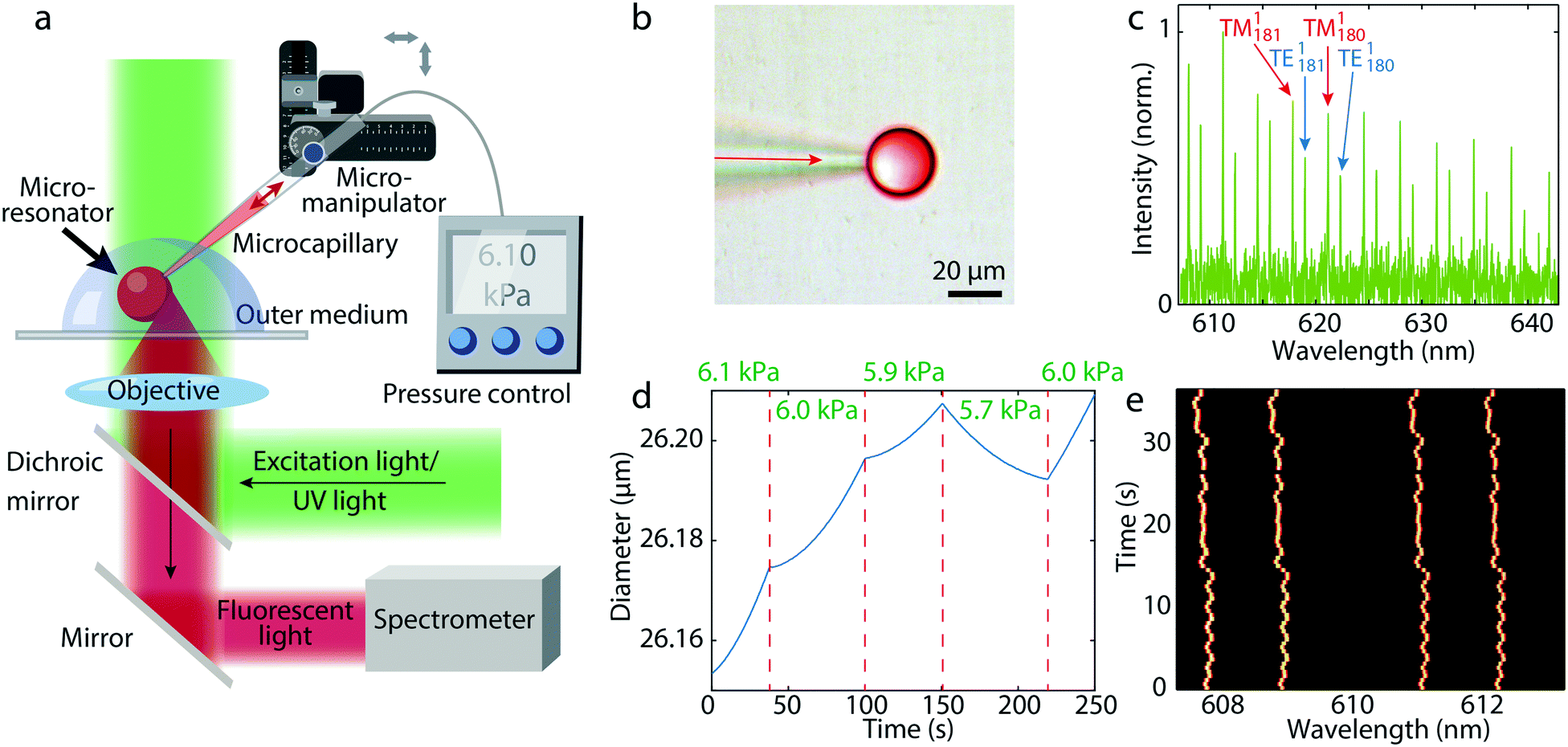 | ||
| Fig. 1 a) Schematics of the setup. After excitation of the dye the fluorescent light which contains WGMs is collected at the droplet surface by an objective lens. b) Combined brightfield and fluorescence image of an oil droplet at the tip of the microcapillary. c) Emission spectrum of such a droplet with the fluorescent background removed and intensity normalized. d) Diameter of a droplet calculated from the WGM spectra when the pressure in the microcapillary is varied. e) WGM spectrum in time with active stabilization of the droplet size. | ||
To obtain an accurate real time size measurement, an algorithm to fit the WGMs has been developed. In general the spectral positions of WGMs are determined by three parameters: diameter of the spherical cavity, internal refractive index and external refractive index. Any two of the three parameters can be measured by fitting to experimental data, while the third parameter has to be known in advance. In the case of oil droplets both refractive indices were known prior to the data acquisition, so only the diameter was fitted, while in the case of photopolymer also the internal refractive index was fitted, since it changed during polymerization. First we fit a Lorentzian function to the experimental spectral peaks to read the peak frequencies of the sharpest family of peaks (the first radial WGMs). For the sake of stability and time efficiency of the algorithm, it employs both the asymptotic and the exact solution for the eigenfrequencies of the WGMs.29,30 We get the exact solution by solving the Maxwell equations for a sphere in a dielectric medium. The boundary condition for the electromagnetic field at the interface provides an equation for determining the eigenfrequencies of the WGMs. Initially, the diameter and the refractive index of the droplet are calculated by fitting the inverse spectral range and the TE–TM-ratio (the spectral distance between TE–TM modes divided by the free spectral range between neighboring TE modes), both averaged over all the modes that appear in the experimentally observed wavelength range. Finally, a better fit for the diameter of the droplet is achieved by overlapping the experimental and theoretical peak positions for a small range of possible diameters around the initially estimated parameters. The theoretical peak positions calculation is the bottleneck for time efficiency of the algorithm, but they can easily be precalculated for the range of diameters and refractive indices of interest. Using this method the standard deviation in the calculated diameter was 0.1 nm, giving a relative error of 4 × 10⁻⁶. The standard deviation of the calculated internal or external refractive index was 10−4 RIU. The absolute uncertainty of the size is limited by the uncertainty of the refractive index, giving an absolute error of 1.5 nm.
In this way we were able to measure the diameter of a droplet very precisely, while the droplet was still in contact with the microcapillary. By applying a pressure larger than the Laplace pressure inside the droplet the oil flows from the microcapillary into the droplet increasing its size, whereas when applying a smaller pressure, the droplet is decreasing in size (Fig. 1d). In this way an extremely precise control of the droplet size is possible. By measuring the size of the droplet, the supplied pressure can be continuously adjusted in real time, thus stabilizing the size of the droplet in long term with an accuracy of 3 nm (Fig. 1e), which is limited only by the precision and response time of our pressure generator.
When a droplet at the end of the microcapillary reached a target size, the microcapillary was moved fast away from the droplet, so that the droplet was released from the tip. A water solution of poly(vinyl alcohol) was used as the outer fluid, which increased the viscosity in order to enable an easier detachment of the droplets. In this way a large number of highly monodisperse droplets can be produced (Fig. 2a). Active stabilization of the droplet size is not needed, since we only want to release the droplet from the microcapillary when it reaches the target size. Initially, the droplets can be either larger or smaller than the target size. Depending on this, a static pressure lower or higher than the Laplace pressure is applied and we wait for the droplet to reach the target size (Fig. 2b). The change of the size of the droplet upon release is negligible and the size after the detachment from the capillary remains constant (Fig. 2c). To demonstrate generation of super monodisperse droplets, we have generated several droplets those spectra matched almost perfectly (Fig. 2d and e). By fitting of WGMs the mean diameter was calculated to be 24.9356 μm with a standard deviation of 1.1 nm. This corresponds to a CV of 0.0042%, which is approximately three orders of magnitude better than droplets typically produced in microfluidics.11 Other batches of produced monodispersed droplets of similar sizes had also the size standard deviation in a 1 nm range (Fig. S1†). Currently, the droplet production rate is in the order of one droplet per minute. However, with better pressure control, wider microcapillary opening for greater flow, faster spectral readout and better feedback algorithm, the production of droplets could be sped up significantly, possibly one per second.
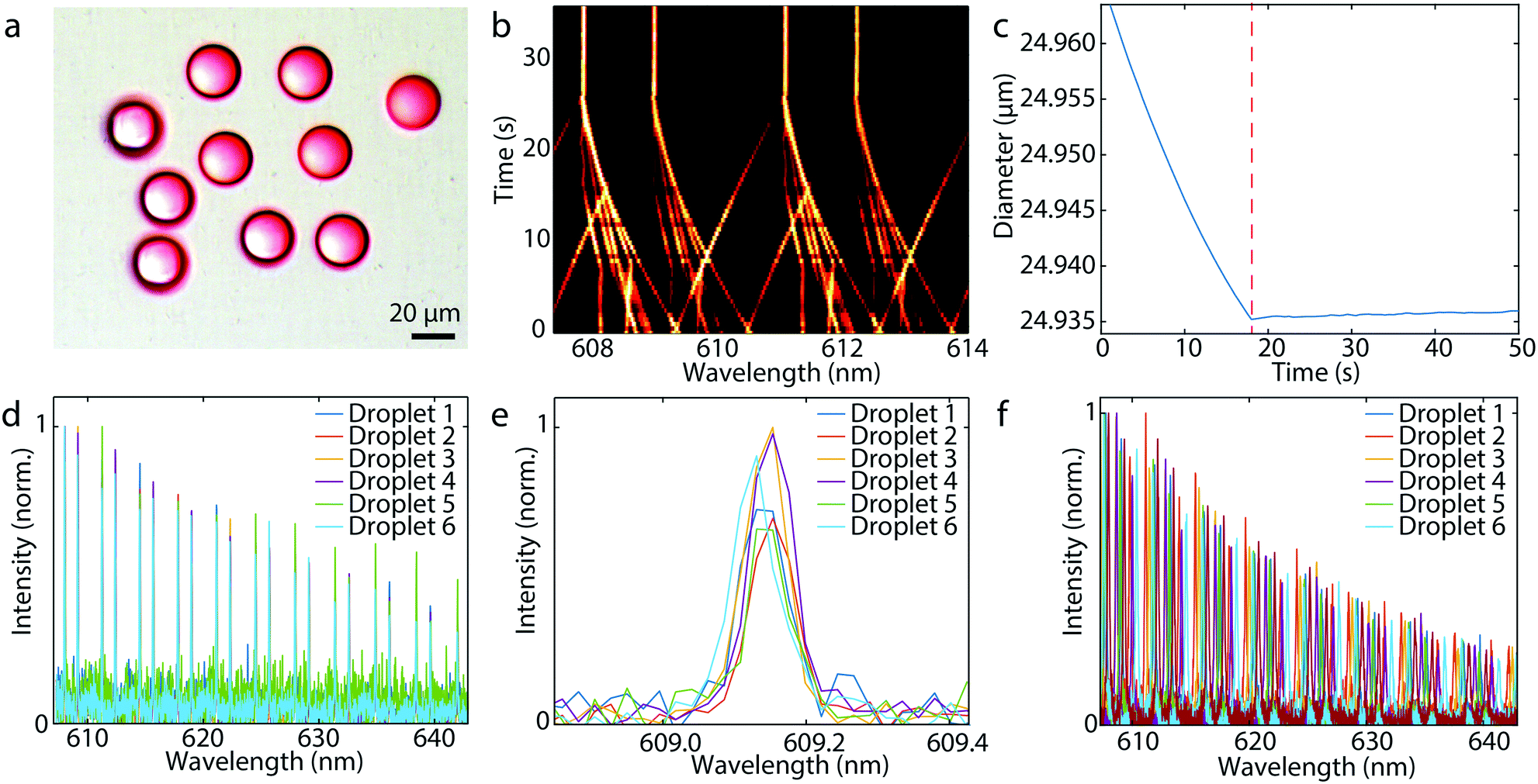 | ||
| Fig. 2 a) Combined brightfield and fluorescence image of identical oil droplets. b) Time evolution of spectra from six droplets when their size was controlled for the same target size. The WGM positions do not shift upon the detachment of the droplet from the capillary at t = 25 s. c) Calculated size of a droplet before and after the release (dotted line) from the microcapillary. d) Spectra of six identical droplets. e) A single spectral peak from the same six droplets showing very good overlap. f) Spectra of six droplets generated without the monitoring of WGMs. | ||
The required condition for using WGMs to monitor the size of the droplets is that the refractive index of the droplet is larger than the refractive index of the outside medium. If we use water-based outside medium, most non-soluble liquids such as oils will be suitable, since a large number of liquids have higher refractive index than water. We can also work with suspended droplets in air, where there is no refractive index limitation. In any case the size of the droplets is also limited by the Q-factor of WGMs. If the droplet is too small, the Q-factors will be low and the peaks will appear wider or will not even be visible. Therefore, a large contrast between the exterior and the interior refractive index is desirable for the WGM detection of smaller droplets. In our case with an exterior refractive index of 1.33 and an interior refractive index of 1.50, the smallest size is 5 μm. On the other end, if the droplet is too large, a large number of WGMs become visible, including higher radial orders, which makes mode identification more difficult. In our case the upper size limit is between 50 μm and 100 μm.
Droplets can also be produced by only applying a predetermined constant pressure for a fixed time, without monitoring the size using WGMs. In this case the droplets have a size standard deviation of 50 nm, for mean diameter of 19.34 μm, corresponding to a CV of 0.27% (Fig. 2f).
2.2 Production of monodisperse solid beads
To make solid microbeads it is straightforward to use a photopolymer for generating the droplets and polymerize them with UV light (Fig. 3a and b). The major consideration to take care of here is the change in size and/or refractive index when the droplet is polymerized. However, we found that these changes are reproducible from droplet to droplet, enabling the production of highly monodisperse solid beads. We used two different approaches to produce the photopolymer droplets (Fig. 3c). The first method was similar to the method described before. Namely, by changing the static pressure inside the microcapillary and monitoring the WGMs while the droplet is still attached we tuned the size of the droplet until it reached the target size before it was released and polymerized. Alternatively, we generated a slightly larger droplet than the target size. Upon the release from the microcapillary it started shrinking due to slight solubility of the photopolymer in water. We monitored the shrinking of the droplet with the WGM signal. Once it reached the target size, we polymerized it to produce a solid microbead. Both methods gave almost same results in the terms of bead monodispersity. In the process of polymerization the size decreased by 0.43 μm ± 0.05 μm and the refractive index increased by 0.011 RIU ± 0.001 RIU. The produced beads had a size standard deviation of 20 nm, for mean diameter of 15.25 μm, corresponding to a CV of 0.13%. The polymerized beads were imaged by scanning electron microscope (SEM) to verify their size (Fig. 3b). The mean diameter measured by SEM was 15.47 μm with standard deviation of 200 nm. The sizes determined by WGMs and SEM matched within 220 nm. This discrepancy may arise from the deformation of the beads due to the polymerization process and/or due to gravitational influence. We have observed that the beads were not completely spherical, but slightly elliptical. The difference between the longer and shorter axis was ∼300 nm. The deformation manifested as WGM line broadening, with full width half maximum of the peaks being 0.4 nm, which matches with the observed magnitude of the deformation.31 We were able to produce solid beads in the diameter range from 5 μm to 50 μm (Fig. S2†).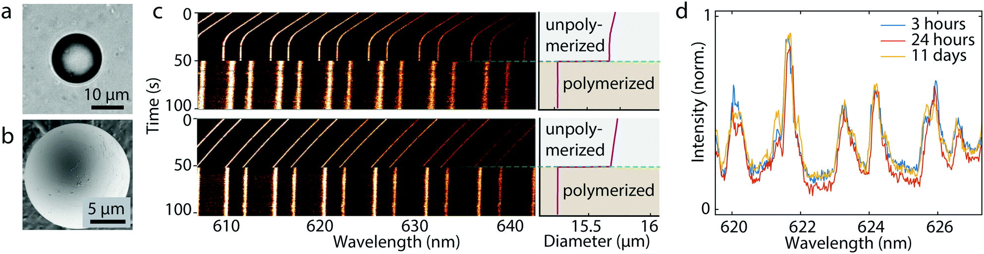 | ||
| Fig. 3 a) Brightfield and b) SEM image of the same bead produced by polymerizing a photopolymer droplet. c) Time evolution of the WGM spectra and droplet diameter before and after the photopolymerization for two size control methods: (top) by tuning the microcapillary pressure and (bottom) by monitoring droplet shrinking. d) Spectrum from a bead 3 hours, 24 hours and 11 days after polymerization. | ||
Stability of solid beads was monitored over several days. As the dispersion of the beads dried out, the beads were dispersed in water again. Size of a bead measured 3 hours, 24 hours and 11 days after polymerization remained stable within 1 nm (Fig. 3d). The size remained almost constant even after 300 days (Fig. S3†). Inspecting the measured values for the free spectral range and full width half maximum we can calculate the finesse 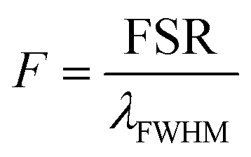 to characterize the generated resonators further. With a calculated finesse of F = 15.4 our beads show similar quality as other reported microresonators.32 In one instance we were able to produce a polymerized microbead with a Q-factor of ∼2900 and a corresponding finesse of F = 24.5 demonstrating the possibility to generate high quality and long living spherical microresonators.
2.3 Spectral information encoding via sizes of WGM cavities
One application which could not have been possible without precisely controlled sphere size is information encoding via size. A microsphere in the size range 20–40 μm which can be produced with a 1 nm precision gives D = 20![[thin space (1/6-em)]](https://www.rsc.org/images/entities/char_2009.gif) 000 unique sizes. This is equivalent to 14 bits of information (log2(D) = 14.3) enabling the encoding of 2 ASCII characters (6-bit encoding) or a 4-digit decimal integer. If more microspheres are used, the number of combinations increases very rapidly. The number of combinations can be calculated as
000 unique sizes. This is equivalent to 14 bits of information (log2(D) = 14.3) enabling the encoding of 2 ASCII characters (6-bit encoding) or a 4-digit decimal integer. If more microspheres are used, the number of combinations increases very rapidly. The number of combinations can be calculated as 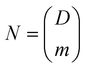 , where m is the number of microspheres. If using three microspheres the number of combinations is
 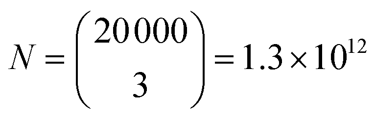 , equivalent to 40 bits of information, encoding 6 ASCII characters (6-bit encoding) or a 12-digit decimal integer. For example, we can encode date and time in a format “dd-mm-yyyy HH:MM”. To show the barcoding ability of our system, we encoded “STEFAN” the surname of a famous Slovenian physicist Jožef Stefan into three droplet sizes using simplified ASCII encoding (see ESI† for encoding details). Due to simplified encoding fewer unique sizes were necessary, so the step size was 4 nm. The target sizes to encode the information were 26.6080 μm, 28.8560 μm and 32.4720 μm. The droplets were produced from silicon oil as described above. The measured diameters of the produced droplets were 26.6086 μm, 28.8568 μm and 32.4716 μm (Fig. 4), all of them 0.8 nm or less from the target size.
 | ||
| Fig. 4 Spectra collected from three beads with predefined sizes. Each vertical bar in the graphical barcode represents position of one spectral line. This graphical barcode is only for visual representation of the positions of the peaks and it does not encode any information. The sizes of the three generated beads calculated from their spectrum encode the word “STEFAN” which is written as a binary number. | ||
The positions of WGMs are dependent on the refractive index of the surrounding medium, which would change the stored information if it had been encoded solely by the spectral positions. However, in our case we can independently measure the bead diameter, which encodes the information, and the external refractive index. So even if the spectrum changes due to the change in refractive index, the information is still preserved. Instead of using exactly three beads of different sizes, a sample can contain an arbitrary number of beads of three distinct sizes. Since the same sized spheres have the same spectrum their number is not important, as long as we collect signal from at least one sphere of each size. To read the spectral information it is enough to illuminate the sample containing the beads with a single nanosecond laser pulse and collect a single spectrum. This has several advantages over conventional barcoding using graphical tags. Namely, the spectral barcode does not need to be imaged, therefore the orientation in the sample is not important. Further, we do not need a complicated imaging system, the signal propagates through scattering media such as skin tissue33 and can also be read through an optical fiber. Further, it has been demonstrated that signal from individual microlasers can be detected from several meters using very simple optics,34 potentially even from several hundred meters, which enables remote readout. To increase the amount of information stored the number of beads can be increased, but only up to a point where there is not too much overlap of the spectral peaks. Up to 5 beads can be easily read simultaneously, possibly even more. Moreover, beads can contain different fluorescent dyes as well as having different refractive index further increasing the number of combinations.
3 Conclusions
Here we presented a simple, reproducible and efficient method to generate multiple precisely sized droplets with the ability to tune the size by monitoring the WGM signal. We demonstrated also the possibility of polymerizing precisely sized droplets in order to obtain monodisperse solid microbeads. In this work the droplets were released by moving the microcapillary. More conveniently, a standard setup for microfluidics droplet generation can be used, for example co-flow microcapillary device. The droplet grows on the tip of the microcapillary until it reaches the desired size, then the outer flow is applied to release the droplet. Preliminary results show that this method is feasible (Fig. S4†). Another alternative for generating monodisperse droplets at a higher rate would be the implementation of a liquid channel containing multiple microcapillaries instead of a single one. Future research can also focus on using WGMs not only to control the size of spherical microresonators but also elongated/elliptical shapes. In that case, the WGM spectrum would show additional modes due to the emergence of additional planes of circulating light expressing new WGM modes.35WGMs are limited to the droplets with high enough refractive index contrast and large enough size. Alternatively, size monitoring could be performed by spectroscopy of reflected white light,36 which can be applied for smaller droplets, even below 1 μm. Recently, multi-cell tagging was demonstrated by the introduction of polymer beads25 or micrometer sized semiconductor disks26 into the cell interior. However, cells are uptaking the microlasers randomly and therefore cell tagging is happening indirectly. Our proposed method could be used to tag the cells directly by injecting a specifically sized microresonator into a specific cell. Due to small size of the barcodes, remote readout and amount of stored information the encoding demonstrated here could be employed for different applications such as tagging of biomedical systems, including implants, pharmaceuticals, individual microparticles, single-cell droplets in microfluidics and even individual cells, as well as for security applications, due to difficulty in counterfeiting these barcodes.
4 Materials and methods
For the generation of droplets poly(dimethylsiloxane-co-methylphenylsiloxane) (Sigma) doped with 0.2–0.5% pyrromethene 580 (1,3,5,7,8-pentamethyl-2,6-di-n-butylpyrromethene-difluoroborate complex, Exciton) was used. The oil has a fractive index of 1.4991 and low viscosity (125 cSt). The outer fluid was a 0.2% solution of poly(vinyl alcohol), (MW 31000, Sigma). For production of beads a fluid UV optical photopolymer was used (Norland 83H) doped with 0.2% pyrromethene 580. Polymerization was carried out by a 100 s exposure at 370 nm with an irradiance of 500 mW cm−2. The injection was performed using a microinjector (FemtoJet, Eppendorf) and a glass micropipette with a 1 μm outer and 0.5 μm inner diameter (Femtotip, Eppendorf). All experiments were performed on an inverted microscope with 20 × 0.50 NA objective and a dichroic beamsplitter with high reflection below 550 nm and high transmission above 550 nm. The light emitted by the droplets was collected by the same objective and sent to either a camera or a spectrometer. The imaging spectrometer (Andor Shamrock SR-500i), with spectral resolution of 0.05 nm and a cooled back illuminated EM-CCD camera (Andor, Newton DU970N) was used. Spectra were recorded at 2 Hz.Author contributions
D. R. performed the experiments. D. R. and M. H. analyzed the data. M. M. developed the algorithms for size fitting and data encoding. D. R., M. M. and M. H. wrote the article. M. H. supervised the study.Conflicts of interest
There are no conflicts to declare.Acknowledgements
The authors would like to thank Andreja Jelen for the SEM images. This work was funded by Slovenian Research Agency (ARRS) (P1-0099, N2-0085, N1-0104, J1-1697) and National Natural Science Foundation of China (61850410528).References
- E. Campos, J. Branquinho, A. S. Carreira, A. Carvalho, P. Coimbra, P. Ferreira and M. Gil, Eur. Polym. J., 2013, 49, 2005–2021 CrossRef CAS.
- S. Rodiger, C. Liebsch, C. Schmidt, W. Lehmann, U. Resch-Genger, U. Schedler and P. Schierack, Microchim. Acta, 2014, 182, 1151–1168 CrossRef.
- X. Wu, Y. Wang, Q. Chen, Y.-C. Chen, X. Li, L. Tong and X. Fan, Photonics Res., 2019, 7, 50–60 CrossRef CAS.
- B. M. Moller, U. Woggon and M. V. Artemyev, Opt. Lett., 2005, 30, 2116–2118 CrossRef.
- S. Damiati, U. B. Kompella, S. A. Damiati and R. Kodzius, Genes, 2018, 9, 103 CrossRef.
- W.-L. Chou, P.-Y. Lee, C.-L. Yang, W.-Y. Huang and Y.-S. Lin, Micromachines, 2015, 6, 1249–1271 CrossRef.
- K. M. Zakir Hossain, U. Patel and I. Ahmed, Prog. Biomater., 2015, 4, 1–19 CrossRef PubMed.
- S. Kawaguchi and K. Ito, Polym. Part., Springer, 2005, pp. 299–328 Search PubMed.
- J. Lee, J. U. Ha, S. Choe, C. S. Lee and S. E. Shim, J. Colloid Interface Sci., 2006, 298, 663–671 CrossRef CAS PubMed.
- H. Qi, W. Hao, H. Xu, J. Zhang and T. Wang, Colloid Polym. Sci., 2009, 287, 243–248 CrossRef CAS.
- P. Zhu and L. Wang, Lab Chip, 2017, 17, 34–75 RSC.
- S. K. Tang, R. Derda, Q. Quan, M. Lončar and G. M. Whitesides, Opt. Express, 2011, 19, 2204–2215 CrossRef CAS PubMed.
- H. Zhang and Y. Sun, Opt. Express, 2018, 26, 11284–11291 CrossRef CAS PubMed.
- S.-X. Qian, J. B. Snow, H.-M. Tzeng and R. K. Chang, Science, 1986, 231, 486–488 CrossRef CAS PubMed.
- B. S. Vaughn, P. J. Tracey and A. J. Trevitt, RSC Adv., 2016, 6, 60215–60222 RSC.
- G. Chen, M. M. Mazumder, R. K. Chang, J. C. Swindal and W. P. Acker, Prog. Energy Combust. Sci., 1996, 22, 163–188 CrossRef CAS.
- F. Vollmer and S. Arnold, Nat. Methods, 2008, 5, 591 CrossRef CAS PubMed.
- F. Vollmer, S. Arnold and D. Keng, Proc. Natl. Acad. Sci. U. S. A., 2008, 105, 20701–20704 CrossRef CAS PubMed.
- M. Humar and S. H. Yun, Nat. Photonics, 2015, 9, 572 CrossRef CAS.
- A. Kiraz, A. Kurt, M. A. Dündar and A. L. Demirel, Appl. Phys. Lett., 2006, 89, 081118 CrossRef.
- H.-M. Tzeng, K. Wall, M. B. Long and R. K. Chang, Opt. Lett., 1984, 9, 273–275 CrossRef CAS PubMed.
- Y. Karadag, M. Mestre and A. Kiraz, Phys. Chem. Chem. Phys., 2009, 11, 7145–7151 RSC.
- A. Kiraz, A. Kurt, M. A. Dündar, M. Y. Yüce and A. L. Demirel, J. Opt. Soc. Am. B, 2007, 24, 1824 CrossRef CAS.
- E. Gil-Santos, C. Baker, A. Lemaître, C. Gomez, G. Leo and I. Favero, Nat. Commun., 2017, 8, 1–7 CrossRef.
- M. Humar, A. Upadhya and S. H. Yun, Lab Chip, 2017, 17, 2777–2784 RSC.
- N. Martino, S. J. Kwok, A. C. Liapis, S. Forward, H. Jang, H.-M. Kim, S. J. Wu, J. Wu, P. H. Dannenberg and S.-J. Jang, et al. , Nat. Photonics, 2019, 13, 720–727 CrossRef CAS.
- M. Schubert, A. Steude, P. Liehm, N. M. Kronenberg, M. Karl, E. C. Campbell, S. J. Powis and M. C. Gather, Nano Lett., 2015, 15, 5647–5652 CrossRef CAS PubMed.
- F. Ramiro-Manzano, R. Fenollosa, E. Xifré-Pérez, M. Garín and F. Meseguer, Adv. Mater., 2011, 23, 3022–3025 CrossRef CAS PubMed.
- S. Schiller, Appl. Opt., 1993, 32, 2181–2185 CrossRef CAS PubMed.
- D. Cohoon, J. Electromagn. Waves Appl., 1989, 3, 421–448 CrossRef.
- N. Riesen, T. Reynolds, A. Francois, M. R. Henderson and T. M. Monro, Opt. Express, 2015, 23, 28896–28904 CrossRef CAS PubMed.
- N. Gaber, M. Malak, F. Marty, D. E. Angelescu, E. Richalota and T. Bourouinaa, Lab Chip, 2014, 14, 2259–2265 RSC.
- M. Humar, A. Dobravec, X. Zhao and S. H. Yun, Optica, 2017, 4, 1080–1085 CrossRef CAS PubMed.
- G. Pirnat, M. Humar and I. Muševič, Opt. Express, 2018, 26, 22615–22625 CrossRef CAS PubMed.
- M. Himmelhaus and A. Francois, Biosens. Bioelectron., 2009, 25, 418–427 CrossRef CAS PubMed.
- Y. Jo, J. Kwon, M. Kim, W. Choi and M. Choi, Nat. Commun., 2018, 9, 4577 CrossRef PubMed.
Footnote |
| † Electronic supplementary information (ESI) available. See DOI: 10.1039/c9lc01034c |
| This journal is © The Royal Society of Chemistry 2020 |