 Open Access Article
Creative Commons Attribution 3.0 Unported Licence
Solvent-free hydrogenation of levulinic acid to γ-valerolactone using a Shvo catalyst precursor: optimization, thermodynamic insights, and life cycle assessment†
Christian A. M. R.
van Slagmaat
 ,
Marie A. F.
Delgove
 ,
Jules
Stouten‡
,
Lukas
Morick‡
,
Yvonne
van der Meer
,
Jules
Stouten‡
,
Lukas
Morick‡
,
Yvonne
van der Meer
 *,
Katrien V.
Bernaerts
 and
Stefaan M. A.
De Wildeman
 *
*
Department of Biobased Materials, Aachen-Maastricht Institute for Biobased Materials, Maastricht University, Brightlands Chemelot Campus, 6167 RD, Geleen, The Netherlands. E-mail: c.vanslagmaat@maastrichtuniversity.nl; yvonne.vandermeer@maastrichtuniversity.nl; s.dewildeman@maastrichtuniversity.nl; Web: https://www.maastrichtuniversity.nl/research/department-biobased-materials
First published on 8th January 2020
Abstract
The hydrogenation of levulinic acid (LA) to γ-valerolactone (GVL) using the η4-(2,3,4,5-tetraphenylcyclopentadienone) ruthenium tricarbonyl precursor of the well-known Shvo catalyst and H2 pressure was established under solvent-free conditions to achieve 100% conversion and 100% selectivity within 5 hours. Kinetic reaction curves were measured in order to deduce the optimal reaction conditions, which were further evaluated by means of density functional theory (DFT) calculations, and compared with catalytic concepts that consume formic acid or isopropyl alcohol as hydrogen donor. Ultimately, this alternative reaction procedure was subjected to a life cycle assessment (LCA) in comparison with the transfer hydrogenation methodologies, in order to verify its contribution towards a practice of environmentally benign chemistry.
1. Introduction
While for the past 150 years many of our fuel, drug, and material needs have been satisfied with fossil-based products, the need to find sustainable bio-based alternatives is ever-increasing with dwindling resources, accelerating global warming, and increasing global turmoil.1 One promising source of such renewable resources is the abundant and widely accessible lignocellulosic material. Much effort over the past decades has gone into the development of technologies to harness the potential of this inherently complex natural material, and cellulose in particular has become an efficient feedstock to produce a large variety of building blocks and fuels.2 Many processes such as fermentation, enzymatic depolymerizations, and acid-catalyzed conversions have become well established in providing mono-sugars or oligomers, which in turn can be transformed further into numerous fine chemicals.3In 2004, the US Department of Energy compiled a list of promising substrates obtainable from carbohydrates, categorizing them according to their anticipated properties in one of nine different fields.4 LA is one of those molecules, that was identified as a platform molecule showing great potential for a large variety of conversions.5 It is shown to be facilely convertible into molecules relevant in a plethora of different applications (Scheme 1). One conversion is particularly relevant in the fields of bio-based solvents,6 fuels,7 and fuel additives:8 the hydrogenation of LA to GVL. In addition, other research identifies the high potential of this molecule as monomer for the synthesis of polymeric materials9 and related applications, such as the conversion to adipic acid via (hydroxy) carbonylation with carbon monoxide or formic acid (FA). The high value of adipic acid in polycondensations creates high interest in this conversion.10 In terms of domestic applications (e.g. cosmetical products,11 lighter- and candle fluids7), beneficial properties of GVL are its high thermal and chemical stability,12 and its pleasant smell.11 GVL also possesses a stereogenic carbon center, which creates opportunities for the manufacture of pharmaceutical products, should enantio-selectivity be achieved.13
 | ||
| Scheme 1 Overview of the conversion of biomass via (hemi)cellulose, furanoic platform molecules, and LA into GVL, and its various applications. | ||
Over the last couple of decades, various catalytic procedures have been established for the hydrogenation of LA to GVL.14 Heterogeneous catalysts are often preferred in chemical industries for advantages, such as facile separation and recycling. However, various homogeneous catalysts recently have entered the spotlights by displaying high activities and excellent – or at least tunable – selectivity towards GVL. Among the homogeneous examples some outstanding turn-over numbers (TON) up to 174![[thin space (1/6-em)]](https://www.rsc.org/images/entities/char_2009.gif) 000 have been reported for catalysts based on ruthenium15 and iridium16 predominantly, while iron17 has recently made its debut.
000 have been reported for catalysts based on ruthenium15 and iridium16 predominantly, while iron17 has recently made its debut.
Other homogeneous catalysts have also shown tolerance to solvent-free conditions. Several in situ catalysts derived from Ru(acac)3 and phosphine ligands were shown to be highly efficient by the groups of Horváth,18 Leitner,19 Mika,15a,20 and Beller,15b whereas full conversions to GVL were selectively achieved under 80–100 bar H2 pressure and temperatures of 135–160 °C. Alternatively, Deng et al. reported the transfer hydrogenation of LA using 1 equivalent of FA catalyzed by RuCl3 with phosphine ligands.21 Other examples of transfer hydrogenation using FA in slight excess (less than 2 equivalents) were demonstrated with Shvo-type catalysts at a milder temperature of 100 °C by Fábos et al.,22 and with dipyridyl-ligated ruthenium23 and iridium16c,23 catalysts by Wang et al. Moreover, the group of Makhubela recently reported ruthenium catalysts with pyrazolylphosphite24 and pyridylimine25 ligands, of which the former one is able to use both FA and H2 as hydrogen donors in low quantities of 1 equivalent and 5–20 bar, respectively, for this conversion. The same group also synthesized polynuclear Ru4^Zn2 complexes with phosphino-carboxylate ligands, which show a remarkably improved activity for such transfer hydrogenations compared to their corresponding monomeric forms.26
Previously, we reported on the comparative study of the Shvo catalyst versus its pre-activated iron analogue, the acetonitrile-appended Knölker catalyst, for the selective hydrogenation of LA to GVL.27 Herein, the catalysis was driven by the hydrogen donors isopropyl alcohol (IPA) and H2 in various solvents. Although appreciable TON's could be achieved by using the iron catalyst, the ruthenium Shvo catalyst was significantly more active. However, the solvent-free form of this chemical transformation using H2 reductant facilitated by the Shvo catalyst is not reported yet, and the absence of added organic solvents herein are envisioned as key to furtherly improve space–time yields significantly, and thereby also reducing the environmental impact of the process. While in transfer hydrogenation the hydrogen donor (e.g. FA, IPA) often co-functions as a solvent and therefore may stabilize the in situ catalytic species,28 the use of H2 under absolute solvent-free conditions is expected to be more challenging. Meanwhile, the use of H2 does not yield any by-products, unlike FA and IPA, which co-produce stoichiometric amounts of carbon dioxide (CO2) and acetone, respectively. Hence, it is expected that this chemical route is environmentally more benign. Furthermore, H2 allows more parameter variation (temperature, pressure) without diminishing the effective reaction volume. On the other hand, using FA as reductant is an eclectic choice as well, since FA is the co-product of the synthesis of LA from 5-hydroxymethylfurfural (HMF) (Scheme 1), and would not require separation before a subsequent hydrogenation step. Hence, we questioned how the choice of hydrogen donor under solvent-free conditions affects the reaction in terms of catalytic performance as well as environmental impact.
Therefore, we established the solvent-free H2-mediated selective hydrogenation of LA to GVL using the monomeric Shvo catalyst precursor Ru-1 in this work, and optimized it in terms of temperature, H2-pressure, and catalyst loading. A possibility for catalyst recycling as well as the role of water in the catalytic mechanism were investigated. Computational DFT experiments were conducted to evaluate the thermodynamic pathways of different hydrogen donors, and these results were validated with the experimental observations. Finally, a LCA evaluating the use of each hydrogen donor in this context was performed.
2. Results and discussion
2.1. Catalyst precursor syntheses and evaluation in catalysis
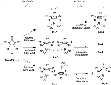
To pursue our findings regarding the activity of the Shvo-type ruthenium catalysts, it was decided to test all three possible precursors. These can be synthesized from triruthenium dodecacarbonyl and tetraphenylcyclopentadienone in refluxing toluene, methanol, or heptane, to yield the monomeric [2,3,4,5-Ph4(η4-C4CO)]Ru(CO)3 (Ru-1), and the dimeric species {[2,3,4,5-Ph4(η4-C4CO)]2H}Ru2(CO)4-(μ-H) (Ru-2) and {[2,3,4,5-Ph4(η4-C4CO)]Ru(CO)2}2 (Ru-3), respectively (Scheme 2, ‘Synthesis’).29 High yields up to 98% for Ru-1 were typically obtained, since this compound can facilely be purified using column chromatography. However, Ru-2 and Ru-3 require precipitation/crystallization in order to be isolated, leading to lower yields in the range of 50–60% in our hands.Exploratory hydrogenation reactions of LA using these catalyst precursors were conducted under solvent-free conditions at 100 °C and under 50 bar H2 pressure for 5 hours.
The control experiments employing no catalytic additive; only the ligand; only Ru3(CO)12; and the ligand plus Ru3(CO)12 (Table 1, entries 1–4, respectively) all rendered no conversions, while significant activity was observed for Ru-1, Ru-2, and Ru-3 with TON's of at least 630 (Table 1, entries 5–7). This observation confirms that the sophisticated organometallic structure of the Shvo catalyst is indeed essential to afford catalytic activity in this reaction, and that in situ generation in LA is not possible. Moreover, the remarkable difference in LA conversion between Ru-1 (63%) and both Ru-2 and Ru-3 (>99%) can be rationalized by the requirement of mono-decarbonylation for Ru-1 in order to be activated (vide infra), while the dimeric Ru-2 and Ru-3 are reported to readily dissociate at 80 °C into monomeric ruthenium species Ru-4 and Ru-5, that are part of the catalytic cycle (Scheme 2, ‘Activation’).22
Alternatively, the structurally related iron Knölker-type catalysts could be realized as a cheaper and greener substitute. In our previous study we concluded the necessity of converting Knölker's complex (Fe-1) into its mono-decarbonylated acetonitrile-appended contender Fe-2, to conveniently afford Casey's catalyst (Fe-3) in situ for the successful hydrogenation of LA in a solvent (ESI, Scheme S1.1†).27 In this work we tested Fe-2 also under solvent-free conditions, but it rapidly decomposed as such, and no LA conversion was observed (Table 1, entry 8). Therefore, the focus was kept on the Shvo catalyst.
Despite the lower activity of Ru-1 compared to its dimeric homologues, we selected this catalyst precursor for further investigation on the basis of the synthetic yields, as well as possible future applications of Shvo type complexes with substituents on the 2- and 5-position, which are too large to allow the dimer formations seen for Ru-2 and Ru-3.30 In addition, this choice gave us the opportunity to elucidate the relation between requiring in situ decarbonylation of Ru-1 and the inhibited LA conversion (63.0%), and how to overcome it.
2.2. Reaction parameter optimizations
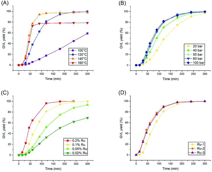
The research was continued by establishing kinetic curves for each experiment using 0.1% Ru-1, in order to observe the effect of systematically altering the reaction conditions. These experiments took place in a batch autoclave reactor, equipped with an external heating mantle, which required 10–15 minutes to heat up the reaction mixture to the desired temperature. Since the t = 0 point is defined as the moment where heating was initiated, the first 15 minutes of the reaction always feature minimal LA conversion.Firstly, the reaction temperature was varied, ranging from 100 to 160 °C (Fig. 1A). While a maximal turn-over frequency (TOF) of 144 h−1 is finally reached after 3 hours at 100 °C, a dramatic increase in activity was achieved at 120 °C, rendering a TOF of 598 h−1 after 30 minutes already, and reaching near-complete conversion within 4 hours. A further increase in activity was observed at 140 °C and 160 °C with maximal local TOF's around 1200 h−1. However, these reactions undergo sudden catalyst deactivation after 60–90 minutes at LA conversions of 97% and 78%, respectively. Thus, an optimal reaction temperature of 120 °C was found for Ru-1, as in agreement with the observation of Casey et al., that decomposition of such complexes starts around 130 °C.31 Next, the H2 pressure was varied from 20 to 100 bar at the optimal reaction temperature of 120 °C (Fig. 1B). In general, a higher TOF was achieved by applying a higher H2 pressure, but a ceiling in activity was observed at 50 bar H2 pressure and higher. Nevertheless, >97% GVL yields were always obtained after 5 hours. As such, 50 bar H2 was selected as the optimal pressure for this reaction.
The concentration effect of Ru-1 was investigated as well (Fig. 1C). Higher reaction rates were observed at higher concentrations of Ru-1, as expected. However, the relative TOFs increased upon lowering the catalyst loading. In order to yield >99% GVL within the convenient time frame of 5 hours, 0.1% Ru-1 should be maintained.
Finally, to retrospectively assess our choice to use Ru-1 in this study, we applied the optimized conditions using Ru-2 and Ru-3 (Fig. 1D). These two dimeric species were observed to become much more readily active within the first 30 minutes than Ru-1, although keeping in mind that the slower LA conversion within the first 15 minutes most likely corresponds to the heating ramp of the autoclave. Consequently, the reactions catalyzed by Ru-2 and Ru-3 finish 1 hour earlier compared to Ru-1. However, their maximal TOF's render 711 and 678 h−1, respectively, which is in the same order of magnitude compared to the rate observed for Ru-1. Hence, despite their immediate activation, Ru-2 and Ru-3 do not bear significant advantages over Ru-1 in terms of catalytic activity.
The sigmoidal curves observed for Ru-1 throughout these kinetic studies could be rationalized further by build-up of water over the course of the hydrogenation reaction, which is proposed as a suitable decarbonylative agent for Ru-1,28,32 as well as for Fe-1.33 Since numerous examples of such catalyst decarbonylations are described using various bases34 or trimethylamine oxide,35 a similar mechanism can be realized with water acting as an Arrhenius base (ESI, Scheme S1.2†). A Karl-Fischer titration of the used LA stock revealed a water concentration of 2022 ppm, which equals 0.002 equivalent with respect to LA. It is plausible this initial presence of water indeed activates a part of the present Ru-1 into Ru-4 upon heating. As such, the LA hydrogenation can be enabled, so that the H2O concentration accumulates further, and pushes the Ru-1 decarbonylation to completion, as observed in the kinetic curves.
2.3. Catalyst recycling studies and the effect of water
Attempts to recycle the catalyst were conducted in a similar manner as earlier reported by Fábos et al.22 Careful vacuum distillation of the reaction mixture yields water (50 °C, 40 mbar) first, and then GVL (90 °C, 1 mbar). The catalyst remains in the residue as an orange solid along with a trace amount of GVL or unreacted LA, and is dissolved in fresh LA for recycling. Unfortunately, after the successful run with fresh catalyst, the conversion of the first and second recycles decreased to 85% and 36%, respectively. This result was surprising, since Fábos et al. reported three successful recycles of Ru-2 without loss of activity.22 Therefore, several possibilities were considered, that may have caused catalyst deactivation in our hands.Firstly, we focused on ascribing this problem to either our hydrogenation procedure, or to the catalyst recovery. To exclude the possibility of catalyst deactivation by exposure to oxygen upon opening the autoclave after the regular reaction time of 5 hours, a 32 hours long experiment with 0.005% Ru-1 at 120 °C and 50 bar H2 was devised, in order to either confirm or dismiss an increased activity compared to the cumulative TONs of the recycling experiments. This reaction rendered a total TON of 9140, upon which a plateau was observed after 10 hours, confirming catalyst deactivation (ESI, Fig. S2.1†). This result suggests a certain aspect in the present hydrogenation procedure to be the critical factor in causing catalyst deactivation.
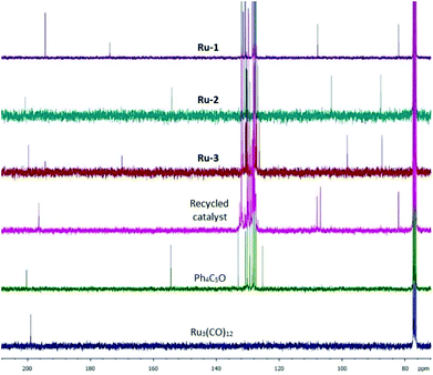
In an attempt to elucidate the catalyst deactivation on molecular level, the catalysts used in one run were isolated in vacuo. 13C NMR analysis of the residual catalyst from the H2-hydrogenation reveals a distinct peak pattern for the three different carbon sets in the cyclopentadienone ring and the metal-bound carbonyls, which do not match with the signals found for Ru-1, Ru-2, and Ru-3, or with the starting materials to synthesize these catalyst precursors (Fig. 2). The disappearance of the signal at 174 ppm and appearance of a signal at 108 ppm may be an indicator for a change in the architecture of the ligand (e.g. deoxygenation), rendering the deactivated material to be a unique species. We also isolated the catalyst used after the FA-mediated transfer hydrogenation for analysis, however, in this case the successful reformation of Ru-2 was observed.
Considering these results, some plausible explanations for the catalyst deactivation appear to rely on differences between this work and the catalytic system of Fábos et al.22 Since our recycling studies were performed at 120 °C instead of 100 °C, while observing catalyst deactivation within 3 hours at 140 °C (Fig. 1A), eventual deactivation at lower temperatures remains a possibility after a longer time. On the other hand, in our work H2 was used as reductant instead of FA. While association of H2 to any of the Shvo catalyst precursors leads to the sensitive Ru-4, association of FA to Ru-2 could potentially yield a stable organometallic adduct in situ.
However, a vital clue was found in the work of Pasini et al., who applied the Shvo catalyst in the hydrogenation of HMF at 90 °C.36 Herein, recycling studies of Ru-2 from both toluene as well as a biphasic water/toluene medium, and the introduction of water was evidenced to be destructive for the catalyst. In light of this information, we sought to eliminate water from LA hydrogenation in this work, and replaced LA by ethyl levulinate (EL), which co-produces ethanol instead of water. Strikingly, the Shvo catalyst applied in this reaction could be reused without losing activity after two recycles (Fig. 3). Moreover, the kinetic curve of EL was found to be practically identical to that of LA hydrogenation under the optimal conditions (ESI, Fig. S2.2†). The use of EL instead of LA is therefore a more preferable substrate for the synthesis of GVL by H2-mediated hydrogenation using Shvo-type catalysts.
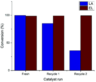 | ||
| Fig. 3 Recycling studies of Ru-1 in the hydrogenation of LA and EL. Conditions: 0.1% Ru-1 in LA (neat) under 50 bar H2 pressure at 120 °C. | ||
Evaluating the role of water in catalyst deactivation further, this concept does not readily apply to the work of Fábos et al.22 However, their three successful catalyst recycles could rely on experimental differences. We believe the use of FA as hydrogen donor is the most likely cause, and possibly manifests via more stabilization of the catalytic species and/or dilution of all components in the reaction mixture.
2.4. Kinetic and thermodynamic comparison of hydrogen donors by DFT calculations
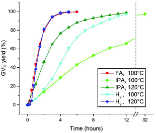
Reflecting on the kinetic reaction profiles at different temperatures in this work, a significantly lower activity is observed for the H2-hydrogenation of LA at 100 °C in this work (Fig. 1A), than for the FA-mediated hydrogenation at 100 °C (with Ru-2), as described by Fábos et al.22 The maximal TOF's for these are 144 h−1 and approximately 400 h−1, respectively. However, upon increasing the temperature of the H2-hydrogenation this difference is annulled. In addition, the hydrogenation of LA with H2 in this work proceeds relatively fast, compared to the transfer hydrogenation with IPA (in toluene at 80 °C), which we reported earlier.27For a fair comparison, we repeated the solvent-free transfer hydrogenations of LA to GVL catalyzed by 0.1% Ru-1 using 2.5 equivalents of FA and IPA, respectively, at 100 °C and 120 °C (Fig. 4). To allow temperatures above the boiling point of IPA, the reactions were performed in an autoclave under 2.5 bar of N2 atmosphere. Since the reaction with FA releases stoichiometric amounts of CO2, a pressurized reaction was not considered feasible and only 100 °C was applied. Moreover, no activation of Ru-1 with FA as hydrogen donor was observed, hence Ru-2 was used instead. At 100 °C reaction rates were observed in the order FA > H2 > IPA, rendering TOF's of 498, 144, and 81 h−1 in the linear regions, respectively. Upon applying an increased temperature of 120 °C to the reactions with H2 and IPA the reaction rates increased to 598 and 257 h−1, respectively.
In order to elucidate these experimental outcomes, DFT calculations were performed. Herein, the goal is to compare the energetic hydrogenation pathways, facilitated by H2, IPA, and FA, and to correlate the results with the experimental findings. The computational structures were optimized using the hybrid B3LYP function,37 and the LANL2DZ core potential38 was applied on all atoms. Unlike some earlier reports,39 in this work the Shvo catalyst was computed without any structural simplification. Since Hollmann et al.40 identified two energetic minima regarding the conformation of the four phenyl rings (i.e. mirror and propeller; Fig. 5), we have taken both conformations into account for these calculations. The energetic difference between these two conformations varies from 0.0 to 2.1 kcal mol−1 throughout our calculated structures, as a result of steric hindrance. However, conformational interchange is considered possible at any stage of the catalytic mechanism.
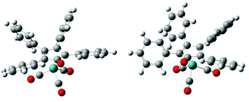 | ||
| Fig. 5 The two different conformations of the phenyl substituents of Ru-1. Left structure is ‘mirror’; right structure is ‘propeller’. | ||
For the hydrogen transfers mediated by the Shvo catalyst, the mechanisms of Assary et al.41 and Casey et al.42 concerning FA and alcohols, respectively, were assumed. The mechanism for the splitting of H2 is also adapted from Casey et al. These structural mechanisms are shown in Fig. 6–8 (vide infra), and always feature a concerted hydrogen transfer, which has been evidenced unanimously before.31,42,43
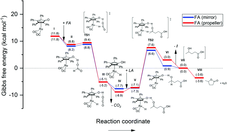 | ||
| Fig. 6 Energetic reaction profile for the regeneration of the active Shvo catalyst species using FA, followed by the Shvo-catalyzed hydrogenation of LA to GVL. The Gibbs free energy is normalized as such, that stage VII equals 0.0 kcal mol−1. A summary of the computational outputs is provided in the ESI.† | ||
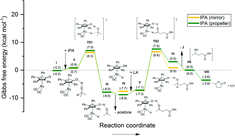 | ||
| Fig. 7 Energetic reaction profile for the regeneration of the active Shvo catalyst species using IPA, followed by the Shvo-catalyzed hydrogenation of LA to GVL. The Gibbs free energy is normalized as such, that stage VII equals 0.0 kcal mol−1. A summary of the computational outputs is provided in the ESI.† | ||
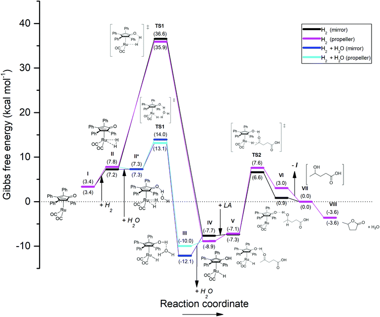 | ||
| Fig. 8 Energetic reaction profile for the regeneration of the active Shvo catalyst species using H2, followed by the Shvo-catalyzed hydrogenation of LA to GVL. The by-pass reaction pathway colored in blue depicts the energetic profile for the splitting of H2 co-catalyzed by a water molecule. The Gibbs free energy is normalized as such, that stage VII equals 0.0 kcal mol−1. A summary of the computational outputs is provided in the ESI.† | ||
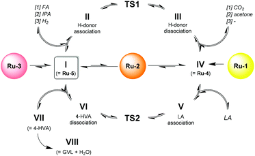
In closer detail, the generic catalytic cycle can be accessed by the formation of either Ru-4, Ru-5, or both, depending on the used catalyst precursor. In Scheme 3, the catalytic cycle starts with Ru-5 (I). From here, a hydrogen donor associates to the catalyst (II), and the transition state is crossed via a concerted heterolytic hydrogen transfer (in case of FA and IPA as hydrogen donors) (TS1). As such, a protonic and a hydridic moiety are generated on the catalyst, while the residual part of the hydrogen donor (if present) has become carbonylic (III), and is then dissociated to form the active 18e− species Ru-4 (IV). Subsequently, LA associates onto Ru-4 in an outer-sphere fashion (V). Next, another transition state is crossed (TS2), corresponding to the concerted transfer of the proton and hydride of Ru-4 to the ketone functionality of LA. Hence, the catalyst is reverted into a 16e− species, while LA is converted into 4-hydroxyvaleric acid (4-HVA) (VI). The catalytic cycle is closed by the dissociation of 4-HVA (VII), however, 4-HVA cyclizes spontaneously into GVL via the extrusion of water (VIII).
The reaction with FA (Fig. 6) was firstly remodeled, since only a simplified version of the Shvo catalyst was reported by Assary et al., who substituted its phenyl groups with hydrogens.41 It should be noted that, although our results are for the larger part qualitatively the same, the presence of the phenyl groups has a significant influence on the Gibbs free energy differentials, that are steric as well as electronic in nature.
Our calculations reveal an energetically favorable association of FA to Ru-5 (step I–II), followed by a practically non-existent transition barrier (ΔGTS1 = 0.0–1.2 kcal mol−1) for the hydrogen transfer (TS1). The subsequent formation and dissociation of CO2 (step TS1 – IV) renders a combined exothermic value of 16.5–18.3 kcal mol−1. In the second part (step IV–VIII), which is identical for all three reactions in terms of ΔG, LA association to Ru-4 appears only slightly endothermic (ΔGTS2 = 0.4–1.8 kcal mol−1), while the hydrogen transfer to LA features a transition barrier of 13.7–14.9 kcal mol−1 (TS2). Ultimately, the dissociation of 4-HVA and its cyclization (step TS2 – VIII) are calculated to be an all-exothermic pathway of 9.2–10.2 kcal mol−1 to yield GVL. This result suggests that activation of Ru-5 by FA (step I to IV) is practically a spontaneous process, and therefore the hydrogen transfer to LA (TS2) is the rate-determining step. Moreover, the pathway from I to IV is unlikely to revert in case of FA, because the gaseous CO2 by-product readily evaporates from the reaction mixture. However, despite such favorable conditions, a minimal temperature of 80 °C is still required, because at lower temperatures Ru-4 tends to dimerize into inactive Ru-2.
The energetic reaction profile for the transfer hydrogenation using IPA was also calculated as a reference to our experimental work reported earlier (Fig. 7).27 Herein, the regeneration of Ru-4 features a slightly endothermic association of IPA to Ru-5 (step I–II), rendering 0.9–1.1 kcal mol−1. This is followed by a transition barrier of 5.4–6.3 kcal mol−1 for the hydrogen transfer (TS1). The subsequent extrusion of acetone renders an exothermic 14.4–15.0 kcal mol−1, which is quantitatively comparable to the energetic barrier of TS2. As such, a rather symmetric energetic profile concerning step I–VII is observed. This correlates with the Meerwein–Ponndorf–Verley equilibrium, however, the reaction is ultimately dragged to completion by the exothermic cyclization of 4-HVA to GVL (step VII–VIII).
Finally, to probe our present work into this thermodynamic context, the pathway in which H2 is heterolytically split by Ru-5 directly was first calculated (Fig. 8, black and purple plots). As such, the catalyst regeneration is initiated by an endothermic association of H2 onto the ruthenium atom of Ru-5, rendering 3.8–4.4 kcal mol−1 (I–II). Then, via transfer of one hydrogen atom to the cyclopentadienone ligand, the transition state for hydrogen splitting is engaged (TS1, black and purple plots), which leads directly to the formation of Ru-4 without the formation of by-products (IV). This process consumes a remarkably high 28.1–29.4 kcal mol−1 for TS1, but releases a seemingly irreversible 43.6–45.5 kcal mol−1 for step TS1 – IV. Hence, the rate-determining step in this scenario appears to be the splitting of H2 instead of hydrogen transfer to LA, unlike the cases for the reactions with FA and IPA.
Although certain values of about 29 kcal mol−1 were reported to be viable for H2 splitting by structurally related iron Knölker-type catalysts,43 this computational outcome does not correlate with our experimental findings. Therefore we also considered an alternative reaction pathway featuring a ‘water-relay’ mechanism (Fig. 8, blue plot), which is evidenced via deuterium labelling studies by Casey et al.42a According to this mechanism, after H2 association to Ru-5 (II), a water molecule associates onto the cyclopentadienone ligand (II*). A transition barrier of only 5.8–6.7 kcal mol−1 is then observed for the water-mediated hydrogen transfer, in which one hydrogen atom from H2 is donated to the oxygen atom of the water, while the water molecule passes one of its own hydrogens to the cyclopentadienone ligand in a concerted way (TS1). The following completion of the hydrogen transfer and dissociation of water (step TS1 – IV) yield Ru-4 as well. Since the transition barrier for water-catalyzed H2 splitting is notably lower compared to that of the ‘dry’ mechanism, and the hydrogenation of LA to GVL co-produces water, we regard only the ‘water-relay’ mechanism as representable for our study. Importantly, the co-catalysis by water causes the energetic barrier of TS1 to become lower than that of TS2, hence turning TS2 into the rate-determining step.
Alternatively, H2 splitting aided by the carboxylic acid functionality of LA is another potential mechanism that could take place in this particular reaction. Although no experimental evidence for H2 splitting by Shvo-type catalysts employing carboxylic acids as co-catalysts is available in literature yet, examples of hydrogen-shuttling induced by phosphoric acids are known,44 of which some also involve the related Knölker catalyst.34b–e,45 Based on the interactions described in these reports and the ‘water-relay’ mechanism by Casey et al.,42a we considered similar concerted mechanisms, in which classical hybridization of the acidic oxygen atoms of LA was assumed. After H2 association to Ru-5 (II), LA associates with its acidic proton to the cyclopentadienone ligand. Then, two modes of concerted H2 splitting co-catalyzed by LA were considered: (a) One hydrogen from H2 migrates to the sp3-hybridized oxygen of LA, which simultaneously donates its own acidic proton to the cyclopentadienone ligand, followed by dissociation of levulinic acid forming Ru-4. This mode is nearly identical to the ‘water-relay’ mechanism in terms of mechanistic atom interactions, as well as the energetic pathway, rendering a transition barrier of 5.4–6.8 kcal mol−1 (ESI, Fig. S4.1†). Hence, this interaction could possibly co-exist with the ‘water-relay’ mechanism in the reaction, but providing spectroscopic distinction between these mechanisms is deemed impossible due to proton-scrambling. (b) The other investigated mode concerns a relay mechanism involving both carboxylic oxygen atoms. One hydrogen from H2 migrates to the sp2-hybridized oxygen of LA, which transfers its electron density via the carboxylic carbon to the sp3-hybridized oxygen, and simultaneously donating the acidic proton to the cyclopentadienone ligand as such, which is most resembling to related interactions by phosphoric acids.34b–e,44,45 This mode of LA association to the Shvo catalyst and H2, as well as the resting state after hydrogen splitting are found more exergonic than the previously described interaction with LA. However, the found transition state for the anticipated concerted hydrogen-transfer mechanism reveals a negative ΔG, and the corresponding molecular vibration is only visible for the splitting of H2, but not for the transfer of the proton from LA to the cyclopentadienone ligand (ESI, Fig. S4.2†). This mismatch suggests that the proposed concerted mechanism in this particular mode may not be existent.
Thus, based on our DFT studies, viable reaction pathways for the Shvo-catalyzed (transfer) hydrogenation of LA to GVL using FA, IPA, H2 + H2O, and one interaction mode for H2 + LA as hydrogen donors were calculated. For each of the four hydrogen donor combinations the hydrogen transfer to LA (TS2) is predicted to be the rate-determining step. On the other hand, the thermodynamic gain for the catalyst activation by the hydrogen donor – and therefore for the entire reaction – is in the order: FA > H2 + H2O = H2 + LA > IPA. Since the magnitude of ΔG co-defines the reaction equilibrium as eqn (1), it also controls the reaction rate by establishing the equilibria throughout step I–VIII. Therefore, the order of ΔG for FA, IPA, H2 + H2O, and H2 + LA is qualitatively in accordance with the observed reaction rates for the corresponding hydrogen donors at equithermal conditions.
 | (1) |
2.5. Life cycle assessment
With the complete, optimized experimental data, and a rational overview of thermodynamic feasibility for all Shvo-catalyzed (transfer) hydrogenations of LA to GVL at hand, it is interesting to identify the most desirable methodology with respect to green chemistry practices. A quantitative expression in terms of environmental impact can be derived from a LCA as an accurate indicator or comparative value for such.LCA is an analytical tool, that is standardized in the ISO 14040 series,46 to assess the environmental impact of a product or service. Herein, the combined total of all material inputs and outputs, energy consumption, and other process attributes (e.g. workup procedures, transport, waste management) are preferably included as complete as possible for an accurate assessment.47
In recent years, numerous LCAs in the field of chemistry have appeared, with the focus on evidencing the benefit of applying bio-based feedstock,48 alternative synthesis routes,49 and innovative procedures.50 However, many of these novel researches are merely conducted in early-development stages, such as laboratory scale or computational process simulations. Hence, their corresponding LCA's are prospective, with the purpose of, for example, identifying the key aspects towards improvement in upscaling,51 or to compare the benefit of choosing a raw material from a selection.48a,52
In this work, we performed a prospective LCA comprising a comparison of several reaction parameters for the Shvo-catalyzed (transfer) hydrogenation of LA to GVL, in terms of environmental impact. These parameters concern the catalyst precursor, hydrogen donor, temperature, and time of the reaction, aiming for the optimal balance between environmental impact and process metrics. The included reactions are described in section 2.4 (Scheme 4), and the function studied in this LCA is the production and isolation of GVL.
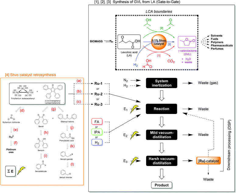 | ||
| Scheme 4 The studied boundaries and process flow-sheet for the production of GVL from LA on laboratory scale: comparative gate-to-gate assessment including [1] the transfer hydrogenation of the substrate using FA as reductant, [2] the transfer hydrogenation of the substrate using IPA as reductant, [3] the hydrogenation of the substrate using H2, and [4] the syntheses of the Shvo catalyst precursors. Reaction conditions: (a) Metalation (in toluene, N2, 110 °C, 24 h, 98%); (b) metalation (in MeOH, N2, 65 °C, 24 h, 51%); (c) metalation (in heptane, N2, 100 °C, 48 h, 58%); (d) carbonylation (ethoxyethanol, CO, KOH, 75–135 °C, 145 min, 96%);54 (e) chlorination (neat, Cl2, 360–390 °C, 8 h, 100%);55 (f) mining/purification/refining;56 (g) aldol condensation (in EtOH, Microwave, 70 °C, 30 min, 78%);57 (h) oxidation (in H2O/AcOH, NH4NO3, 1% Cu(II)OAc2, 100 °C, 2.5 h, 94%);58 (i) Benzoin condensation (in DMSO, Ar, NaCN, Ultrasound, 25 °C, 10 min, 98%);59 (j) Dakin-West reaction (neat, N2, Ac2O, Et3N, 25 °C, 48 h, 69%);60 (k) hydrolysis (in H2O/H2SO4, 100 °C, 3 h, 78%);61 (l) Kolbe nitrile synthesis (in H2O, NaCN, 80 °C, 4 h, 85%).62 Reactions a–c are conducted in this work, reactions d–l are adapted from literature procedures. Additional chemicals (i.e. ethoxyethanol for reaction d, copper sulfate for reaction h, and triethylamine for reaction j), required in these syntheses, of which the impact could not be derived from the database, were assessed on the basis of literature procedures as well.63 Electricity consumptions are denoted as “E” (see ESI Table S5.1† for details). Dashed arrows indicate an optional reaction- or DSP-pathway. | ||
The life cycle inventory (LCI) comprises three different hydrogenation methods, which are [1] transfer hydrogenation using FA and emitting CO2, [2] transfer hydrogenation using IPA and co-producing acetone, and [3] direct hydrogenation using H2 without generating any by-product. Herein, the boundaries of this LCA are chosen to be ‘gate-to-gate’ for the production and isolation of GVL from LA (Scheme 4). This means that the environmental impact of consumed chemicals, electric energy input, and downstream processing (DSP) are taken into account for this chemical transformation, but not for the synthesis of LA from primary resources. Excluding the environmental impact of LA synthesis can only provide reliable comparisons, if the assessed LA hydrogenations achieve 100% conversion to GVL with complete isolation. We consider it reasonable to assume this for the present work, given that all the actual LA conversions equal at least 97%. The choice for this boundary was made, because the only reported LCA on LA production to our knowledge is based on a process model and is too specific with respect to a location or feedstock,47b and is therefore not representative for this work. Moreover, as GVL provides a very wide versatility in further applications and products, its ‘end-of-life’ scenario is regarded as yet undefined in this work. The applied Shvo catalyst precursors were modelled as ‘cradle-to-gate’ (vide infra), to demonstrate the environmental impact for their synthesis and use in this reaction.4
The present LCA is modelled in accordance with the experimental execution described in sections 2.2, 2.3, and 2.4. All hydrogenation reactions were performed on laboratory scale, rendering 20–43 g of GVL product. However, to apply a uniform comparison on representative scale, the functional unit (FU) was chosen as 10 g of GVL, being in accordance with the product category rules (PCR) of the environmental product declaration (EPD).53
As shown in Scheme 4, the procedure for converting LA to GVL is initiated by creating an inert atmosphere for the reaction by purging with nitrogen (and optionally H2, in case of direct hydrogenation). The purged gas is released from the system, thus regarded as waste. In the next step, the (transfer) hydrogenation reaction takes place, for which any of the Shvo-type catalyst precursors, any of the three different hydrogen donors, and electric energy are the input. The environmental impact of LA is not taken into account here, since this LCA is a ‘gate-to-gate’ assessment. Depending on the scenario, residual nitrogen or H2, or CO2 by-product are considered as waste. The GVL product is isolated via the DSP steps, which consume electric energy for heating and cooling water circulation. First, a mild vacuum distillation is applied to remove water, and any residual liquid hydrogen donor (i.e. FA, IPA), and acetone by-product if present. In the harsh vacuum distillation, pure GVL is distilled from the catalyst. The spent catalyst is discarded in the main scenario, however, catalyst recovery from the distillation residue and recycling is considered in the sensitivity analysis (vide infra).
For the assessment of Ru-1, Ru-2, and Ru-3, a plausible retrosynthesis was devised on the basis of standard laboratory scale reports found in literature (Scheme 4).54–62 Firstly, these Shvo-type catalyst precursors are conventionally synthesized from tetraphenyl-cyclopentadienone and triruthenium dodecacarbonyl, as shown in Scheme 2. Although various procedures for synthesis and purification with different isolated yields exist in literature,22,29,57,64,65 those acquired from the present work are adopted as the base case in this LCA. Furthermore, the ligand is produced via the double aldol condensation of benzil and diphenyl ketone,57 which are ultimately derived from benzaldehyde and benzyl chloride, respectively. The triruthenium dodecacarbonyl is ultimately produced from metallic ruthenium,55,56 which is a by-product from platinum ore mining, purification, and refining processes.56
The total procedure for the (transfer) hydrogenation reactions, product isolation, and the catalyst synthesis routes were modelled in Simapro V8 (PRé consultants, NL). The environmental impacts were calculated using the IMPACT 2002+ V2.14 method, and the results are generally expressed as damage categories.66 However, mid-point categories were used for the life cycle impact assessment interpretations. The climate change impact was calculated with the IPCC GWP 100a mid-point method, in accordance with the updated method from the Intergovernmental Panel on Climate Change (IPCC).67
The potential environmental impacts of the five different hydrogenation scenarios, were investigated on four different end-point categories, and scaled with respect to the functional unit:
(1) Damage to human health, expressed in disability-adjusted life year (DALY). This includes human toxicity, respiratory effects, ionizing radiation, ozone-layer depletion, and photochemical oxidation.
(2) Ecosystem quality, expressed in potentially disappeared fraction of species per m2 per year (PDF m−2 year−1). Herein, aspects for both aquatic and terrestrial ecotoxicity (e.g. acidification, eutrophication, land occupation) are taken into account.
(3) Climate change, as a result from greenhouse gas emissions into the environment. The severity of the impact per emission type is scaled to kg CO2 equivalents, in accordance with the global warming potential (GWP) as conversion factor, provided by the IPCC.67
(4) Resources, expressed in MJ, are calculated by the sum of energy derived from non-renewable feedstock and mineral extractions.
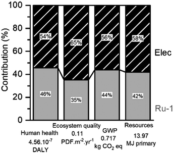
For the optimized H2-hydrogenation at 120 °C, the relative contributions of process features to the damage categories are presented in Fig. 9. Remarkably, the largest contributors to nearly the entire environmental impact are the electric energy consumption required for the hydrogenation reaction and the catalyst synthesis. This is also found for the other reaction scenarios (ESI S5.1†), but their impact distribution slightly differs. Herein, a trend between the electric energy impact and the reaction duration is clearly visible. However, the lowest electric impact found for the FA-mediated reaction can be rationalized by having the reaction performed in a reflux setup, instead of using an autoclave. Despite the small numerical difference, the impact of H2 consumption appears notably lower than that of FA or IPA. Since the four damage categories always indicate a similar impact distribution, only the GWP was selected for further investigations.
The catalyst synthesis delivers a large part of the impact to this reaction process, while its loading counts only 0.1 mol% with respect to LA. Therefore, it is considered worthy to identify the cause of this result, and how to improve it. First, the GWP's of the hydrogenation reactions were modelled as a function of the isolated catalyst yields (Fig. 10). The curves indicate significant reductions of the GWP in all hydrogenation scenarios, however, the relatively highest reductions are seen for the FA- and H2-mediated reactions. The yield of Ru-1 in this work is already an excellent 98%. Contrarily, improving our isolated yield of 51% for Ru-2 could reduce the GWP of the corresponding FA-mediated hydrogenation reaction up to 27%.
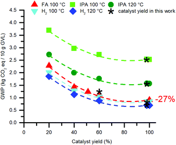 | ||
| Fig. 10 Reduction of the environmental impact of the catalyst by improving its isolated yield. The catalyst synthesis concerns Ru-1, but for the FA-mediated reaction Ru-2 is modelled. | ||
It should be mentioned though, that the GWP of the catalyst is strongly dependent of the applied synthetic procedure as well as the DSP methodology, and isolated yield. Throughout various literature procedures for synthesizing Ru-1,64Ru-2,22,29,57 and Ru-365 the electricity consumption originating from the reaction duration and the solvent amount used for column chromatography are found to be the most dominant impact factors (ESI, Fig. S5.2†). The variation in these aspects significantly affects the total GWP of the LA hydrogenation reactions (Fig. 11).
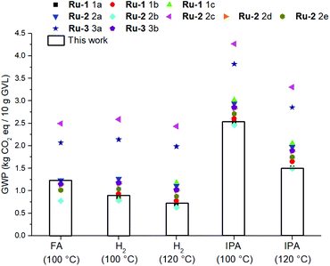 | ||
| Fig. 11 Sensitivity analysis of the catalyst syntheses in relation to the GWP of the hydrogenation reactions. | ||
Nevertheless, by considering the isolated yields of Ru-1 and Ru-2 obtained in this work, the magnitude of the environmental impact of LA hydrogenation in terms of H-donors is in the order: IPA > FA > H2 (Fig. 11). To eliminate the difference in GWP caused by significantly different isolated yields amongst Ru-1 and Ru-2, but not neglecting the incompatibility of Ru-1 with FA, a combinatorial comparison was devised between the optimal reaction conditions for using each H-donor, and applying each Shvo catalyst precursor with a modelled 98% isolated yield (ESI S5.3†). Also in this hypothetical circumstance the use of H2 as H-donor shows the lowest GWP.
The environmental impact of the FA-mediated reaction could arguably be reduced in two ways. Since FA is a concomitant by-product from the hydrolysis of HMF to LA (Scheme 1), 1 equivalent of FA can be bio-derived from the same feedstock. As such, the environmental impact for the separation of LA from FA could then be eliminated, however, this separation step is not included within the gate-to-gate boundaries of this LCA. Secondly, Fábos et al. have demonstrated the use of only 0.5 equivalents of excess FA to be feasible for 99.9% conversion,22 while 1.5 excessive equivalents were used in this work. Hence, the effects of these two potential eliminations of petrochemical formic acid were assessed in our catalytic system, but even the combination of these effects inflict only a lean 2% reduction of the GWP (ESI S5.4†).
To furtherly decrease the impact of the catalyst synthesis, the benefit of potential recycling was assessed. Although we concluded that recycling of the Shvo catalyst is incompatible with LA because of deactivation by co-produced water (section 2.3, Fig. 3), it is still interesting to investigate its hypothetical recycling as a model for the EL hydrogenation or even other reactions outside this work. The corresponding calculation can be described by dividing the GWP accounting for the catalyst synthesis by the number of each following hydrogenation cycle, but not for the DSP, as this recurs in each cycle. The obtained plot (ESI, Fig. 5.5†) reveals a decreasing decline after each recycle, leading to a reduction from 44% to less than 7% of the total GWP for the hydrogenation reaction after ten recycles, compared to a reaction without catalyst recycling. Beyond this point an asymptote is reached, whereas 147 recycles are required to draw the catalyst's impact below 1%. We consider a minimum of ten recycles without losing catalytic activity a proper goal to thrive for.
In addition, a further decrease of the environmental impact could be envisioned by immobilizing the catalyst. Supported Shvo-type complexes are known,68 and their application would allow facile catalyst separation by filtration. As such, the harsh distillation step in the DSP can be omitted, which reduces the environmental impact by 31%. However, it is important to mention that immobilizing the Shvo catalyst requires extra synthesis steps, which increases the impact of the catalyst synthesis in turn, and catalyst decomposition by sensitivity to water may still occur. In addition, the GVL product is likely to be of lower purity, because in this scenario GVL is collected from the mild distillation residue.
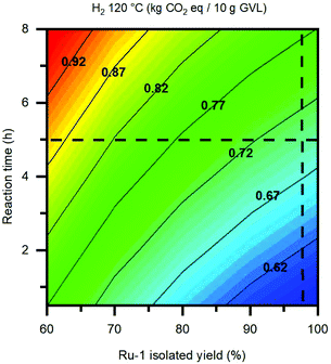
Finally, the duration of the hydrogenation reaction is regarded as the other vital parameter in terms of environmental impact, whereas it is directly proportional to the reaction's electricity consumption. While the applied reaction temperature is one significant factor, also the choice of H-donor plays a dominant role, resulting from the differences in thermodynamic properties amongst the three reaction pathways, as demonstrated by the DFT studies in section 2.4. Based on the kinetic reaction curve in Fig. 1D, a minimum in environmental impact could potentially be realised by mitigating between a shorter reaction time and slightly lower GVL yield. For the LA hydrogenation catalyzed by Ru-1 it is possible to shorten the reaction time for at least 1 hour, while being reacted at 120 °C under 50 bar H2. However, applying a reaction time under 2 hours goes severely at the cost of the GVL yield, and is therefore deemed not feasible. To illustrate this in a numerical fashion, the GWP was plotted as a function of the reaction time and the isolated yield for Ru-1, which are the two largest contributors to the environmental impact of the base case LA hydrogenation in this work (Fig. 12). In this way, an environmentally optimal combination of the reaction parameter values can be pinpointed, in order to achieve the lowest impact possible. In the case of the present reaction, the isolated yield for Ru-1 (98%) can hardly be improved. However, by shortening the reaction time from 5 hours to 3 hours, an appreciable decrease of 0.5 kg CO2 eq. per 10 g GVL, corresponding to 7%, can be achieved. LCA representations of this kind can make a useful tool to predict the optimal reaction metrics for developing chemical reactions on laboratory scale into large-scale processes, in the context of green chemistry practices.
3. Conclusions
This multi-disciplinary study describes the selective hydrogenation of LA to GVL under solvent-free conditions using the Shvo catalyst. In this specific reaction, the use of hydrogen gas as reducing agent is the novelty, for which the effects of various reaction conditions were thoroughly investigated by means of kinetic studies using the monomeric Shvo-type catalyst Ru-1. The optimal laboratory scale protocol to yield 99.7% conversion within 5 hours is achieved by heating at 120 °C under 50 bar H2, using 0.1 mol% [Ru], and this applies to each of the possible Shvo catalyst precursors known.Attempts to recycle the catalyst from the LA hydrogenation were not successful, since the co-produced water appears to deactivate the catalyst. However, successful catalyst recycling can be achieved by substituting LA for EL, which renders an identical kinetic plot in the same hydrogenation reaction, but co-produces ethanol instead of water.
The comparison of H2versus other hydrogen donors – FA and IPA – under similar solvent-free conditions result in significantly different reaction rates, in the order of FA > H2 > IPA. Computational modelling of each reaction using DFT indicate the energetic transition barrier for hydrogen splitting/transfer generating the active catalytic species, and also the overall exothermic energy loss to be the determining factors in these reaction rates. In addition, the role of water in co-catalyzing H2 splitting via a relay mechanism was considered as a more plausible reaction pathway than direct H2 splitting, based on the magnitude of their energetic transition barriers. As such, the interpretation of the DFT study correlates properly with the experimental observations.
To identify the optimal hydrogen donor from an environmental perspective, the LA hydrogenation procedures featuring the three different hydrogen donors were subjected to a comparative gate-to-gate LCA. Herein, the environmental impacts of the Shvo catalyst precursors are modelled as a cradle-to-gate LCA, mostly based on secondary literature-derived information. The results reveal for all (transfer) hydrogenation reactions, that the total electricity consumption and the catalyst synthesis are the main contributors to the environmental impact with a combined part of ≥95%. Sensitivity analysis of these factors shows that a significant variation in the GWP is possible, depending on the reaction duration/temperature/thermodynamics, and synthetic procedure, respectively. Therefore, effectively decreasing the environmental impact could be established by balancing out the reaction time versus the GVL yield, and to apply catalyst recycling (if possible) for at least 10 times.
However, in the optimistic-realistic scenario, where all reactions are assumed to achieve 100% conversion within their applied optimal reaction conditions, and all catalyst precursor yields are normalized to 98%, the magnitude of environmental impact renders IPA ≫ FA > H2. Hence, the present LCA demonstrates the use of H2 to be the ‘greenest’ choice, originating from the short reaction time compared to the reaction with IPA, and to the absence of the stoichiometric CO2 by-product compared to the reaction with FA. We expect the environmental benefit of using H2 to be more pronounced in scaled-up facilities, which generally display a much higher energy efficiency than laboratory-scale equipment.
With this research, we would also like to emphasize the value of combining different research interests and methodologies in today's chemistry, whereas the interfaces between them may create a pivotal synergy in understanding the chemistry, and therefore how to achieve the greenest and most efficient process.
Conflicts of interest
The authors state that there are no conflicts to declare.Acknowledgements
This work was performed within the framework of the public-private knowledge institute of Chemelot InSciTe, who we gratefully acknowledge for their financial support.References
- (a) G. W. Huber, S. Iborra and A. Corma, Chem. Rev., 2006, 106, 4044 CrossRef CAS PubMed; (b) A. Corma, S. Iborra and A. Velty, Chem. Rev., 2007, 107, 2411 CrossRef CAS PubMed; (c) J. J. Bozell and G. R. Petersen, Green Chem., 2010, 12, 539 RSC.
- (a) R. C. Saxena, D. K. Adhikari and H. B. Goyal, Renewable Sustainable Energy Rev., 2009, 13, 167 CrossRef; (b) P. Mäki-Arvela, B. Holmbom, T. Salmi and D. Y. Murzin, Catal. Rev., 2007, 49, 197 CrossRef; (c) G. Centi, P. Lanzafame and S. Perathoner, Catal. Today, 2011, 167, 14 CrossRef CAS; (d) R. Serrano-Ruiz, A. Luque and A. Sepulveda-Escribano, Chem. Soc. Rev., 2011, 40, 5266 RSC.
- (a) K. H. Kim, M. Tucker and Q. Nguyen, Bioresour. Technol., 2005, 96, 1249–1255 CrossRef CAS PubMed; (b) A. Fukuoka and P. L. Dhepe, Angew. Chem., Int. Ed., 2006, 45, 5161–5163 CrossRef CAS PubMed; (c) P. Lenihan, A. Orozco, E. O'Neill, M. N. M. Ahmad, D. W. Rooney and G. M. Walker, Chem. Eng. J., 2010, 156, 395–403 CrossRef CAS; (d) D. M. Alonso, J. Q. Bond and A. Dumesic, Green Chem., 2010, 12, 1493–1513 RSC.
- T. Werpy, G. Petersen, A. Aden, J. Bozell, J. Holladay, J. White and A. Manheim, in Top Value Added Chemicals from Biomass: Volume 1 – Results of Screening for Potential Candidates from Sugars and Synthesis Gas, ed. T. Werpy and G. Petersen, U. S. Department of Energy, Washington, DC, 2004 Search PubMed.
- (a) L. Qi, Y. F. Mui, S. W. Lo, M. Y. Lui, G. R. Akien and I. T. Horváth, Chem. Commun., 2012, 48, 5850 RSC; (b) L. Yan, Q. Yao and Y. Fu, Green Chem., 2017, 19, 5527 RSC.
- (a) I. T. Horváth, Green Chem., 2008, 10, 1024 RSC; (b) J. Q. Bond, D. Wang, D. M. Alonso and J. A. Dumesic, J. Catal., 2011, 281, 290 CrossRef CAS; (c) J. Q. Bond, D. M. Alonso, D. Wang, R. M. West and J. A. Dumesic, Science, 2010, 327, 1110 CrossRef CAS PubMed; (d) D. Fegyverneki, L. Orhá, G. Láng and I. T. Horváth, Tetrahedron, 2010, 66, 1078 CrossRef CAS; (e) A. Strádi, M. Molnár, M. Óvári, G. Dibó, F. U. Richter and L. T. Mika, Green Chem., 2013, 15(7), 1857 RSC; (f) L. Qi, Y. F. Mui, S. W. Lo, M. Y. Liu, G. R. Akien and I. T. Horváth, ACS Catal., 2015, 4, 1470 CrossRef.
- V. Fábos, M. Y. Lui, Y. F. Mui, Y. Y. Wong, L. T. Mika, L. Qi, E. Cséfalvay, V. Kovács, T. Szucs and I. T. Horváth, ACS Sustainable Chem. Eng., 2015, 3, 1899 CrossRef.
- J.-P. Lange, R. Price, P. M. Ayoub, J. Louis, L. Petrus, L. Clarke and H. Gosselink, Angew. Chem., Int. Ed., 2010, 49, 4479 CrossRef CAS PubMed.
- (a) C. W. Lee, R. Urakawa and Y. Kimura, Eur. Polym. J., 1998, 34, 117 CrossRef CAS; (b) M. Chalid, H. J. Heeres and A. A. Broekhuis, J. Appl. Polym. Sci., 2012, 123, 3556 CrossRef CAS; (c) M. Chalid, H. J. Heeres and A. A. Broekhuis, Polym.-Plast. Technol. Eng., 2015, 54, 234 CrossRef CAS.
- J. G. de Vries, Top. Catal., 2014, 57, 1306 CrossRef CAS.
- Good Scents Company, Parfumery Raw Materials Information Sheet, http://www.thegoodscentscompany.com/data/rw1024031.html.
- (a) I. T. Horváth, H. Mehdi, V. Fábos, L. Boda and L. T. Mika, Green Chem., 2008, 10, 238–242 RSC; (b) C. Y. Y. Wong, A. W-T. Choi, M. Y. Lui, B. Fridrich, A. K. Horváth, L. T. Mika and I. T. Horváth, Struct. Chem., 2017, 28, 423 CrossRef CAS.
- (a) A. K. Ghosh and L. J. Swanson, Org. Chem., 2003, 68, 9823 CrossRef CAS; (b) E. L. Stangeland and T. J. Sammakia, Org. Chem., 2004, 69, 2381 CrossRef CAS PubMed; (c) R. Datrika, S. R. Kallam, S. R. Khobare, V. S. Gajare, M. Kommi, H. R. Mohan, V. Siddaiah and T. Pratap, Tetrahedron: Asymmetry, 2016, 27, 603 CrossRef CAS.
- (a) W. H. R. Wright and R. Palkovits, ChemSusChem, 2012, 5, 1657 CrossRef CAS PubMed; (b) U. Omoruyi, S. Page, J. Hallett and P. W. Miller, ChemSusChem, 2016, 9, 2037 CrossRef CAS PubMed.
- (a) J. M. Tukacs, M. Novák, G. Dibó and L. T. Mika, Catal. Sci. Technol., 2014, 4, 2908 RSC; (b) A. Dutta Chowdhury, R. Jackstell and M. Beller, ChemCatChem, 2014, 6, 3630 CrossRef.
- (a) W. Li, J. Xie, H. Li and Q. Zhou, Green Chem., 2012, 14, 2388 RSC; (b) J. Deng, Y. Wang, T. Pan, Q. Xu, Q. Guo and Y. Fu, ChemSusChem, 2013, 6, 1163 CrossRef CAS; (c) S. Wang, H. Huang, V. Dorcet, T. Roisnel, C. Bruneau and C. Fischmeister, Organometallics, 2017, 36, 3152 CrossRef CAS.
- Y. Yi, H. Liu, L.-P. Xiao, B. Wang and G. Song, ChemSusChem, 2018, 11, 1474 CrossRef CAS.
- H. Mehdi, V. Fábos, R. Tuba, A. Bodor, L. T. Mika and I. T. Horváth, Top. Catal., 2008, 48, 49 CrossRef CAS.
- F. M. A. Geilen, B. Engendahl, A. Harwardt, W. Marquardt, J. Klankermayer and W. Leitner, Angew. Chem., Int. Ed., 2010, 49, 5510 CrossRef CAS PubMed.
- J. M. Tukacs, D. Király, A. Strádi, G. Novodarszki, Z. Eke, G. Dibó, T. Kégl and L. T. Mika, Green Chem., 2012, 14, 2057 RSC.
- L. Deng, J. Li, D. M. Lai, Y. Fu and Q.-X. Guo, Angew. Chem., Int. Ed., 2009, 48, 6529 CrossRef CAS PubMed.
- V. Fábos, L. T. Mika and I. T. Horvath, Organometallics, 2014, 33, 181 CrossRef.
- S. Wang, V. Dorcet, T. Roisnel, C. Bruneau and C. Fischmeister, Organometallics, 2016, 36, 708 CrossRef.
- G. Amenuvor, B. C. E. Makhubela and J. Darkwa, ACS Sustainable Chem. Eng., 2016, 4, 6010 CrossRef CAS.
- N. K. Oklu and B. C. E. Makhubela, Inorg. Chim. Acta, 2018, 482, 460 CrossRef CAS.
- G. Amenuvor, J. Darkwa and B. C. E. Makhubela, Catal. Sci. Technol., 2018, 8, 2370 RSC.
- C. A. M. R. van Slagmaat and S. M. A. De Wildeman, Eur. J. Inorg. Chem., 2018, 6, 694 CrossRef.
- H. M. Jung, S. T. Shin, Y. H. Kim, M.-J. Kim and J. Park, Organometallics, 2001, 20, 3370 CrossRef CAS.
- B. L. Conley, M. K. Pennington-Boggio, E. Boz and T. J. Williams, Chem. Rev., 2010, 110, 19 CrossRef PubMed.
- C. P. Casey and H. Guan, Organometallics, 2012, 31, 2631 CrossRef CAS PubMed.
- C. P. Casey, S. Singer, D. R. Powell, R. K. Hayashi and M. Kavana, J. Am. Chem. Soc., 2001, 123, 1090 CrossRef CAS PubMed (ref. 54.
- Y. Shvo and D. Czarkie, J. Organomet. Chem., 1986, 315, C25 CrossRef CAS.
- M. K. Thorson, K. L. Klinkel, J. Wang and T. J. Williams, Eur. J. Inorg. Chem., 2009, 2, 295 CrossRef.
- (a) A. Tlili, J. Schranck, H. Neumann and M. Beller, Chem. – Eur. J., 2012, 18, 15935 CrossRef CAS PubMed; (b) S. Zhou, S. Fleischer, K. Junge and M. Beller, Angew. Chem., Int. Ed., 2011, 50, 5120 CrossRef CAS PubMed; (c) S. Fleischer, S. Werkmeister, S. Zhou, K. Junge and M. Beller, Chem. – Eur. J., 2012, 18, 9005 CrossRef CAS PubMed; (d) S. Fleischer, S. Zhou, S. Werkmeister, K. Junge and M. Beller, Chem. – Eur. J., 2013, 19, 4997 CrossRef CAS PubMed; (e) S. Zhou, S. Fleischer, H. Jiao, K. Junge and M. Beller, Adv. Synth. Catal., 2014, 356, 3451 CrossRef CAS; (f) K. Natte, W. Li, S. Zhou, H. Neumann and X. F. Wu, Tetrahedron Lett., 2015, 56, 1118 CrossRef CAS.
- (a) S. A. Moyer and T. W. Funk, Tetrahedron Lett., 2010, 51, 5430 CrossRef CAS; (b) A. Pagnoux-Ozherelyeva, N. Pannetier, M. D. Mbaye, S. Gaillard and J.-L. Renaud, Angew. Chem., Int. Ed., 2012, 51, 4976 CrossRef CAS PubMed; (c) D. S. Merel, M. Elie, J. F. Lohier, S. Gaillard and J.-L. Renaud, ChemCatChem, 2013, 5, 2939 CrossRef CAS; (d) B. Emayavaramban, M. Roy and B. Sundararaju, Chem. – Eur. J., 2016, 22, 3952 CrossRef CAS PubMed.
- T. Pasini, G. Solinas, V. Zanotti, S. Albonetti, F. Cavani, A. Vaccari, A. Mazzanti, S. Ranieri and R. Mazzoni, Dalton Trans., 2014, 43, 10224–10234 RSC.
- (a) P. J. Stevens, F. J. Devlin, C. F. Chablowski and M. J. Frisch, J. Phys. Chem., 1994, 98, 11623 CrossRef; (b) A. D. Becke, J. Chem. Phys., 1993, 98, 5648 CrossRef CAS.
- (a) P. J. Hay and W. R. Wadt, J. Chem. Phys., 1985, 82, 299 CrossRef CAS; (b) S. Huizinga, J. Anzelm, M. Klobukowski, E. Radzio-Andzelm, Y. Sakai and H. Tatewaki, Gaussian Basis Sets for Molecular Calculations, Elsevier, Amsterdam, 1984 Search PubMed.
- (a) A. Comas-Vives, G. Ujaque and A. Lledós, Organometallics, 2007, 26, 4135 CrossRef CAS; (b) A. Comas-Vives, G. Ujaque and A. Lledós, J. Mol. Struct.: THEOCHEM, 2009, 307, 123 CrossRef.
- D. Hollmann, H. Jiao, A. Spannenberg, S. Bähn, A. Tillack, R. Parton, R. Altink and M. Beller, Organometallics, 2009, 28, 473 CrossRef CAS.
- R. S. Assary and L. A. Curtiss, Chem. Phys. Lett., 2012, 541, 21 CrossRef CAS.
- (a) C. P. Casey and J. B. Johnson, Can. J. Chem., 2005, 83, 1339 CrossRef CAS; (b) C. P. Casey and J. B. Johnson, J. Am. Chem. Soc., 2005, 127, 1883 CrossRef CAS PubMed; (c) C. P. Casey, J. B. Johnson, S. W. Singer and Q. Cui, J. Am. Chem. Soc., 2004, 127, 3100 CrossRef PubMed.
- (a) S. Moulin, H. Dentel, A. Pagnoux-Ozherelyeva, S. Gaillard, A. Poater, L. Cavallo, J.-F. Lohier and J.-L. Renaud, Chem. – Eur. J., 2013, 19, 17881 CrossRef CAS PubMed; (b) T.-T. Thai, D. S. Mérel, A. Poater, S. Gaillard and J.-L. Renaud, Chem. – Eur. J., 2015, 21, 7066 CrossRef CAS PubMed.
- (a) B. Xu, S.-F. Zhu, Z.-C. Zhang, Z.-X. Yu, Y. Ma and Q.-L. Zhou, Chem. Sci., 2014, 5, 1442 RSC; (b) Y.-Y. Ren, S.-F. Zhu and Q.-L. Zhou, Org. Biomol. Chem., 2018, 16, 3087 RSC.
- K. Hopmann, Chem. – Eur. J., 2015, 21, 10020 CrossRef CAS.
- ISO 14044: 2006, Environmental Management – Life Cycle Assessment – Requirements and Guidelines, International Organization for Standardization, 2006.
- (a) D. Kralisch, D. Ott and D. Gericke, Green Chem., 2015, 17, 123 RSC; (b) V. Isoni, D. Kumbang, P. N. Sharratt and H. H. Khoo, J. Environ. Manage., 2018, 214, 267 CrossRef CAS PubMed.
- (a) H. H. Khoo, W. L. Ee and V. Isoni, Green Chem., 2016, 18, 1912 RSC; (b) R. Mazzoni, C. Cesari, V. Zanotti, C. Lucarelli, T. Tabanelli, F. Puzzo, F. Passarini, E. Neri, G. Marani, R. Prati, F. Viganò, A. Conversano and F. Cavani, ACS Sustainable Chem. Eng., 2019, 7, 224 CrossRef CAS.
- (a) Z. Wang, Z. Li, T. Lei, M. Yang, T. Qi, L. Lin, X. Xin, A. Ajayebi, Y. Yang, X. He and X. Yan, Appl. Energy, 2016, 183, 170 CrossRef CAS; (b) M. A. F. Delgove, A. B. Laurent, J. M. Woodly, S. M. A. De Wildeman, K. V. Bernaerts and Y. van der Meer, ChemSusChem, 2019, 12, 1349 CrossRef CAS PubMed.
- (a) C. Koroneos, A. Dompros, G. Roumbas and N. Moussiopoulos, Int. J. Hydrogen Energy, 2004, 29, 1443 CrossRef CAS; (b) S. Rivas, A. M. Raspolli-Galletti, C. Antonetti, V. Santos and J. C. Parajó, J. Wood Chem. Technol., 2015, 35, 315 CrossRef CAS.
- R. Arvidsson, A.-M. Tillman, B. A. Sandén, M. Janssen, A. Nordelöf, D. Kushnir and S. Molander, J. Ind. Ecol., 2018, 22, 1286 CrossRef CAS.
- H. H. Khoo, L. L. Wong, J. Tan, V. Isoni and P. Sharratt, Resour., Conserv. Recycl., 2014, 95, 174 CrossRef.
- Environmental Product Declaration (EPD) – PCR Basic Module – Basic Chemicals CPC 34 (v3.0), 2017.
- M. Fauré, C. Saccavini and G. Lavigne, Chem. Commun., 2003, 1578 RSC.
- (a) H. Remy, Z. Anorg. Allg. Chem., 1924, 137, 365 CrossRef CAS; (b) W. P. Griffith, Platinum Metals Rev., 1975, 19, 60 CAS.
- P. Nuss and M. J. Eckelman, Met. Environ. Impacts, 2014, 9, e101298 Search PubMed.
- C. Cesari, L. Sambri, S. Zacchini, V. Zanotti and R. Mazzoni, Organometallics, 2014, 33, 2814 CrossRef CAS.
- D. X. Klein, T. A. Girard and H. R. Johnson; assignors to Heyden Chemical Corporation, New York, N.Y., a corporation of Delaware, US2658920, 1951.
- J. Safari, N. M. Arani and A. R. Esfahani, Asian J. Chem., 2011, 23(6), 495–498 CAS.
- K.-V. Tran and D. Bickar, J. Org. Chem., 2006, 71, 6640 CrossRef CAS.
- R. Adams and A. F. Thal, Benzyl cyanide, Org. Synth., 1922, 2, 59 CrossRef , collective vol. 1, p36.
- R. Adams and A. F. Thal, Benzyl cyanide, Org. Synth., 1922, 2, 9 CrossRef , collective vol. 2, p63.
- (a) J. Y. Bae, S-H. Park, W-X. Cai and J-H. Zhen, Preparation of glycol ether (line 0027), JPH07206744A, 1995; (b) H. W. Richardson, Copper Compounds, Ullmann's Encyclopedia of Industrial Chemistry, Wiley-VHC, Weinheim, 2005 Search PubMed; (c) G. Zhou, L. Feng, Q. Sun, A. Wang, T. Song and Q. Qi, The method of producing high selectivity triethylamine (example 4, line 0060–0062), CN104370748B, 2016.
- (a) M. I. Bruce and J. R. Knight, J. Organomet. Chem., 1968, 12, 411 CrossRef CAS; (b) B. A. Persson, A. L. E. Larsson, M. Le Ray and J.-E. Bäckvall, J. Am. Chem. Soc., 1999, 121, 1645 CrossRef CAS.
- M. J. Mays, M. J. Morris, P. R. Raithby, Y. Shvo and D. Czarkie, Organometallics, 1989, 8, 1162 CrossRef CAS.
- O. Jolliet, M. Margni, R. Charles, S. Humbert, J. Payet, G. Rebitzer and R. Rosenbaum, Int. J. Life Cycle Assess., 2003, 8, 324 CrossRef.
- Fifth Assessment Report, The Physical Science Basis, Intergovernmental Panel on Climate Change, 2013.
- (a) J. H. Choi, N. Kim, Y. J. Shin, J. H. Park and J. Park, Tetrahedron Lett., 2004, 45, 4607 CrossRef CAS; (b) D. G. Hanna, S. Shylesh, P. A. Parada and A. T. Bell, J. Catal., 2014, 311, 52 CrossRef CAS; (c) D. He and I. T. Horváth, J. Organomet. Chem., 2017, 847, 263 CrossRef CAS.
Footnotes |
| † Electronic supplementary information (ESI) available. See DOI: 10.1039/c9gc02088h |
| ‡ These authors contributed equally to this work. |
| This journal is © The Royal Society of Chemistry 2020 |

