 Open Access Article
Low-temperature carbon-based electrodes in perovskite solar cells
Dmitry
Bogachuk
 ab,
Salma
Zouhair
abc,
Konrad
Wojciechowski
 de,
Bowen
Yang
 f,
Vivek
Babu
d,
Lukas
Wagner
 ab,
Bo
Xu
g,
Jaekeun
Lim
ab,
Simone
Mastroianni
ah,
Henrik
Pettersson
g,
Anders
Hagfeldt
ab,
Bo
Xu
g,
Jaekeun
Lim
ab,
Simone
Mastroianni
ah,
Henrik
Pettersson
g,
Anders
Hagfeldt
 fg and
Andreas
Hinsch
*a
aDepartment of Organic and Perovskite Photovoltaics, Fraunhofer Institute for Solar Energy Systems ISE, Heidenhofstr. 2, 79110 Freiburg, Germany. E-mail: dmitry.bogachuk@ise.fraunhofer.de; andreas.hinsch@ise.fraunhofer.de
bINATECH, Albert-Ludwigs-Universität Freiburg, Emmy-Noether-str. 2, 79110 Freiburg, Germany
cThin films and nanomaterials laboratory, Faculty of Sciences and Techniques (FST), 90000 Tangier, Morocco
dSaule Technologies, Wroclaw Technology Park, 11 Dunska, 54-427, Wroclaw, Poland
eSaule Research Institute, Wroclaw Technology Park, 11 Dunska, 54-427, Wroclaw, Poland
fLaboratory of Photomolecular Science, Institute of Chemical Sciences and Engineering, École Polytechnique Fédérale de Lausanne (EPFL), Lausanne CH-1015, Switzerland
gDyenamo AB, Teknikringen 38A, SE-114 28 Stockholm, Sweden
hMaterials Research Center FMF, Albert-Ludwigs-Universität Freiburg, Stefan-Maier-str. 21, 79104 Freiburg, Germany
First published on 10th September 2020
Abstract
Carbon-based electrodes have been widely applied in perovskite solar cells (PSCs) because of their chemical inertness and compatibility with up-scalable techniques, signifying their solid potential for mass-production. The material scarcity and complexity of metal ore extraction further highlights that conventionally used noble metal electrodes cannot represent a sustainable option for back-contact in PSCs, while cells with carbon-based electrodes represent an excellent solution to these problems. However, their power conversion efficiencies (PCEs) still lag behind the traditionally processed cells with metal electrodes, resulting in a considerable efficiency gap. To overcome this issue, we propose the use of low-temperature carbon-based (LTCB) electrodes, which offer several key advantages in comparison to mesoscopic high-temperature treated ones: (1) larger choice of selective layers, (2) applicability to all perovskite crystallization methods, (3) compatibility with flexible substrates and (4) faster deposition process. In this review, we analyze numerous techniques to formulate the LTCB-paste and ways to deposit it on the cell stack which have been developed in order to improve the interfacial contact and electrode conductivity. Besides describing the current state-of-the-art perovskite solar cells with LTCB-electrodes, the most promising strategies to enhance the PCE of such photovoltaic (PV) devices are discussed. Overall, we emphasize that PSCs with a LTCB-electrode combine high device stability, low manufacturing costs and low environmental impact, while having options for pushing the efficiency of carbon-based PSCs closer to the record-breaking cells, all of which are vital in order to fulfill the true potential of perovskite PV.
Broader contextIn order to meet the growing energy demand of the global population and prevent large amounts of green-house emissions, renewable energy sources need to be utilized to a maximum extent. Photovoltaics (PV) is one of the fastest developing renewable energy fields, yet the world electricity share of PV is still below 3%. Halide perovskite photovoltaics is an emerging technology that will decrease the levelized cost of electricity and has a strong potential to become a commercially attractive alternative to conventional silicon-based solar modules, increasing the share of PV power generation in the global energy mix. Although, perovskite photovoltaics have experienced unprecedented development in the last few years, there are stability and cost issues related to the organic hole-conductors and noble metals, used as back-electrodes. Minimization of the CO2-footprint of perovskite solar devices requires replacement of the metals with low-cost and sustainable materials, such as carbon-based layers. Most importantly, carbon-based layers provide an excellent chemical and operational stability. Two types of carbon-based electrodes have been successfully developed recently, which are processed at high- and low-temperatures. In this review, we outline the advantage of low-temperature carbon-based contacts, which are most promising to reach the highest power conversion efficiencies in long-term stable perovskite PV devices. |
1. Introduction
Ever since the potential of perovskite materials in solar cell applications was discovered in 2009,1 the photovoltaic (PV) community is still nowadays being impressed by their exceptional light-absorbing and opto-electronic properties. One of the appealing points of this type of photovoltaic device is the versatility of the semiconductor crystal structure.2–4 This phenomenal tunability of various fundamental properties fuels the intensive research activities across the globe and makes them attractive to researchers not only in the field of PV, but also in the disciplines of light-emitting-diodes (LEDs),5–8 photodetectors,9–12 sensors13–16 and electrochemical cells.17–19 In PV applications, once the device efficiencies became comparable to those of the well-established technologies such as mono- or poly-crystalline silicon, the aspect of performance stability became the center of attention for scientists working on perovskite PV.20–24Considering the nature of metal-halide perovskite, it has been noticed that one of its most-appealing points – low energetic barrier for crystal formation – is also one of its biggest drawbacks.25 This peculiar material characteristic allows for quick liquid processing during cell production, while simultaneously possessing “soft ionic crystal” properties prone to multiple defects and degradation mechanisms due to weak metal-halide bonds.25–28 Over the years, researchers have developed countless techniques to solve the instability problem of perovskite solar cells (PSCs). However, it is still a challenge to combine highly efficient light absorption and charge extraction with stable performance in one perovskite device.
Generally, most of the cells are fabricated on a transparent substrate, coated with conductive oxide (e.g. FTO, ITO) which functions as a front electrode. The charge selectivity in perovskite cells is obtained by placing a photoabsorber between hole and electron-selective contacts. The cell configuration, where on the transparent front contact an electron selective layer (ESL), perovskite and a hole-selective layer (HSL) are sequentially deposited, is commonly referred to as an n–i–p structure. The cell stack is completed by a counter- or back-electrode. Both electrodes allow an effective lateral charge conduction, while the charge selective layers extract photogenerated electrons and holes from the perovskite and further conduct them to the electrode. The cell structure can also be inverted, resulting in the p–i–n configuration. Some p- and n-layers can only be interchangeably employed, and the question of which device structure offers best power conversion efficiencies (PCEs) and performance stability is still under debate.
Carbon-based perovskite solar cells (C-PSCs) are a cell concept that has been introduced to sort the issues of instability, manufacturing complexity and high costs faced by record-breaking metal/HSL-based PSCs.29 The hydrophobic nature of carbon promotes lower in-take of moisture into the cell, making it possible to improve the cell lifetime.30,31 Additionally, carbon electrodes have proved their ability to extract photogenerated holes by themselves allowing researchers to manufacture PSCs without the need of using expensive and unstable HSLs, promoting the concept of HSL-free monolithic perovskite solar cells.32 Conventional carbon-based PSCs use carbon black and graphite as counter electrodes, that require high processing temperatures to burn out the organic binder.33,34 This review aims to explore the recent promising progress of low temperature carbon-based PSCs, along with their unique potential to meet the optimal point for game-changing and disruptive PV: low cost, high stability, high efficiency and sustainability (Fig. 1).
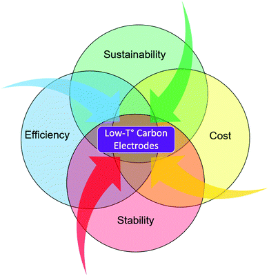 | ||
| Fig. 1 Illustration of the main characteristics that are required for perovskite to become the next generation PV technology, where we identify low-T° carbon as the key element to reach that goal. | ||
Here, we briefly highlight the main challenges of traditional perovskite PV, namely the device stability, high manufacturing costs, up-scaling and environmental impact, followed by a discussion of how carbon-based cells can overcome these drawbacks. Different concepts of C-PSCs are described as well as the key advantages of low-temperature processed C-PSCs over the high-temperature processed ones. Later, we discuss the recent developments in low-temperature carbon-paste formulations and methods of depositing such a layer on a cell. Finally, we propose a number of strategies to close the efficiency gap between the traditional PSCs and low-temperature carbon-based ones.
2. Motivation behind perovskite solar cells with carbon-based electrodes
2.1. Stability issue in perovskite solar cells
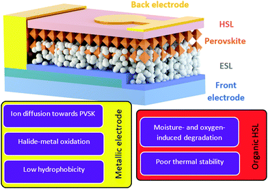
It is well-known that perovskite solar cells are more susceptible to degradation than mature PV technologies such as amorphous/crystalline Si and thin film technologies (e.g. CdTe, CIGS).35,36 Many systematic investigations and review publications have shown that the degradation of perovskite is an extremely complex problem including issues related to moisture, oxygen, UV light, heat and electrical bias.37–41 Moreover, this also makes the assessment of PSC stability complicated as it highly depends on the measurement conditions. To resolve this ambiguity, scientists in the perovskite community have recently proposed a number of standardized procedures for studying the stability of perovskite PV devices based on ISOS protocols.42 In this review we would like to focus the reader's attention on the intrinsic stability of back contacts and organic hole-selective layers that are implemented in PSCs (Fig. 2). Therefore, the main degradation mechanisms related to the ambient environment, containing oxygen and moisture, are accentuated in this chapter.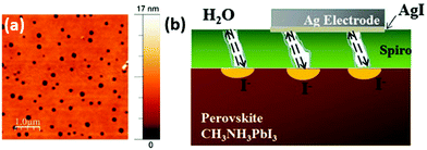 | ||
| Fig. 3 (a) AFM images of the spiro-OMeTAD layer surface with multiple pinholes of 135 nm average diameter. (b) Schematic drawing of the perovskite degradation and halide diffusion in the presence of pin-holes in spiro-OMeTAD. Adapted and reproduced with permission from ref. 69 and 70. | ||
Some studies have attempted to develop efficient HSL-free PSCs to overcome this issue. Etgar et al. reported an HSL-free concept for perovskite solar cells with a CH3NH3PbI3/TiO2 heterojunction cell yielding a PCE of 5.5%.83 The idea consisted of having a thick perovskite layer on top of the mesoporous TiO2 acting both as a photoabsorber and selective layer.
On the other hand, inorganic HSLs such as NiOx and CuI can offer much better chemical stability and carrier mobility than the organic ones.30,64,84 You et al. have demonstrated how PSCs with PEDOT:PSS completely deteriorate over the course of 5 days in an ambient environment (25 °C with 30–50% humidity), while the ones with NiOx as HSL maintained their initial PCE for almost 60 days.64 Although in most cases NiOx serves as a p-contact in p–i–n cells, there are also several reports displaying the capability of NiOx to be integrated on top of perovskite. A low-temperature processing of NiOx was reported by Liu et al., where the metal oxide nanoparticles were capped with stearate ligand and dispersed in a non-polar solvent chlorobenzene.85 However, the p–i–n devices with such NiOx layer have shown better PCE than the n–i–p devices due to remaining ligands at the perovskite/HSL interface, hindering the hole-extraction. Cao et al. have demonstrated another low-temperature method to deposit NiOx on top of perovskite, which provided higher thermal stability of the PSC, in comparison to cells with spiro-OMeTAD and copper thiocyanate (CuSCN).86 Thermally-induced degradation in the samples with spiro-OMeTAD was attributed to the formation of morphological defects at the perovskite/HSL interface, whereas the reaction between perovskite and CuSCN at increased temperatures was found to jeopardize the cell stability. Zhang et al. have proposed the use of CuGaO2 as an efficient and stable HSL, which can be deposited on top of perovskite, resulting in a better device PCE and stability than that of devices with spiro-OMeTAD (Fig. 4).87 The suppressed interfacial recombination and lower dark saturation current (J0) were determined to be the origins of the PCE improvement, whereas the stability enhancement was attributed to less hydrophilic properties of the CuGaO2.
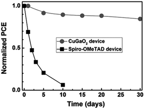 | ||
| Fig. 4 Normalized PCE of PSCs with CuGaO2 and spiro-OMeTAD as HSLs measured under an ambient environment (RH = 30–55%, T = 25 °C). Adapted and reproduced with permissions from ref. 87. | ||
The reported findings in the literature show that, as anticipated, some inorganic HSLs exhibit higher stability than the organic ones, because of their lower affinity for water and higher structural robustness in an ambient environment.45 Moreover, inorganic materials typically exhibit higher thermal stability30 as well as the ability to retard sublimation of volatile perovskite components (e.g. HI and CH3NH2) and layer decomposition.88 This is an important note, as in n–i–p cells the HSLs should protect the moisture- and oxygen-sensitive perovskite photoabsorber and not accelerate its deterioration.
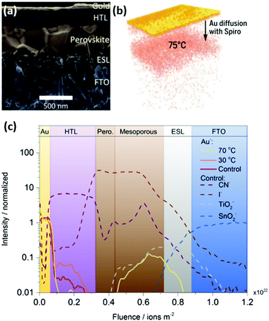 | ||
| Fig. 5 (a) Solar cell stack with m-TiO2 (ESL), perovskite, spiro-OMeTAD (HTL) and gold cathode. (b) Reconstructed 3D map of gold diffusion towards the perovskite, accelerated by higher temperatures. (c) Time-of-flight SIMS profile of the aged cell-stack. Adapted and reproduced with permission from ref. 22 and 89. | ||
Multiple studies have shown that PSCs with silver contact degrade due to the tendency of Ag+ ions to diffuse towards perovskite and due to the formation of silver halides, arising from an oxidation reaction with migrated I− ions or with volatile perovskite degradation products (e.g. HI) as depicted in Fig. 6.90,93–96 The Cu electrode can be easily oxidized in the presence of air and moisture, leading to increased series resistance losses in PSCs.30 Also, its oxidation products can react with perovskite decomposition products such as HI, which further deteriorates the perovskite.97 Notably, over the last few years, more materials such as reduced graphene oxide,98 bismuth99 and transparent conductive oxides95 have been implemented as barrier layers to reduce the metal-electrode induced degradation. Nevertheless, the fundamental mechanisms inducing water- and metal-induced degradation remain and even in the presence of interfacial modifications, there remains a risk that future barrier development will not enable long term stabilities in the order of decades, as currently warranted for silicon PV modules. This suggests that, regarding the current research status, metal-electrode based PSCs might not be able to achieve long-term device stabilities.100 Indeed, to the best of our knowledge, today the longest demonstrated operational stability of metal-based PSCs is 5000 h (illuminated with intensity of 13 mW cm−2, which is almost 1/8 of the Sun irradiation intensity, under relative humidity of 70%), which is still too low for passing international PV standards of long-term stability.24,47,101
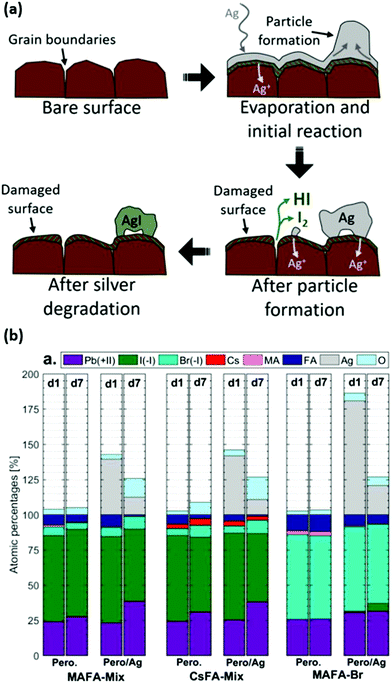 | ||
| Fig. 6 (a) Model of the silver degradation in the presence of mobile volatile species (e.g. HI, I2) and I− and Ag+ ions in perovskite. (b) The relative elemental percentage of each species at the surface, determined from core level XPS analysis of the pure perovskite (noted as Pero.) and when the Ag is deposited on top (Pero/Ag) for different perovskite cation compositions on day 1 (d1) and day 7 (d7). Adapted and reproduced with permission from ref. 93. | ||
It needs to be mentioned that despite strong stability disadvantages of organic HSLs and metallic contacts, there has been tremendous progress in developing encapsulation techniques to bring the decomposition reactions to equilibrium and prevent the PCE deterioration of such devices. Glass–glass encapsulation as well as the use of edge-seal technology have been proposed, although low perovskite decomposition temperature presents a challenge for selecting a benign sealant. The authors demonstrated how such encapsulation provides a sufficient protection against the ambient environment and improves cell stability, namely, the fabricated encapsulated PSCs could withstand damp heat, dry heat and thermal cycling tests.103 Recently Shi et al. reported how encapsulation with polyisobutylene provided an effective moisture barrier, surpassing over 1800 h of damp-heat test and over 70 humidity-freeze test cycles, meeting the requirements set by the IEC61215:2016 standard.104
Although, undoubtedly, encapsulation helps to reduce the moisture ingress into the photovoltaic device, the stability of the photoabsorber, selective layers and cathode materials still needs to be considered and effective strategies to passivate perovskite and mitigate decomposition reactions need to be developed besides encapsulation. For example, Liu et al. have demonstrated implementation of interfacial engineering in perovskite solar modules, which provided a moderate operational stability. Although the encapsulated device retained 86% of the initial PCE after 2000 h of operation under AM1.5G illumination,105 the authors noted that the modules without encapsulation had a similar operational stability, highlighting that encapsulation can only partially prevent the deterioration of the perovskite photovoltaic device and the main stability improvements should be achieved via PSC architecture modification, for example by replacing metallic electrodes with the carbon-based ones.
Deposition of the carbon-based contact on top of the monolithic cell stack is one of the most promising routes to prolong the lifetime of a perovskite PV device. In this case, carbon-based electrodes are typically >5 μm thick, meaning that the over-excess of perovskite can be applied in its porous structure, which makes it more tolerant against the decomposition in the photo-absorber. In 2014, Mei et al. employed a mixed-dimensional perovskite of (5-AVA)x(MA)1−xPbI3 into mesoscopic carbon-based HSL-free perovskite solar cells, resulting in a stable certified PCE of 12.8% (>1000 h) under ambient air and full sunlight without encapsulation.32 Notably, Grancini et al., in collaboration with the company Solaronix, reported an outstanding 10![[thin space (1/6-em)]](https://www.rsc.org/images/entities/char_2009.gif) 000 h stability (Fig. 7a) with the same device structure, whereas the PCE of the n–i–p cell (with the same photoabsorber layer) with the spiro-OMeTAD layer and Au electrode, decreased by almost 40% relatively to the initial value after only 300 h of continuous 1 Sun illumination.112 Zhou et al. have shown how a low-temperature processed carbon layer is able to repel water better than Au and Ag metal electrodes, resulting in a better overall performance stability without encapsulation.107 Ye et al. have shown how a planar cell with Zn-doped SnO2 as ESL, CuPc as HSL and a carbon electrode gave a stable PCE close to 18% for 1200 h without encapsulation.113 Zhang et al. have demonstrated a cell with 19.2% PCE with 1000 h stability, where a carbon-based electrode was deposited on top of the HSL by press-transferring a self-adhesive carbon film.114
000 h stability (Fig. 7a) with the same device structure, whereas the PCE of the n–i–p cell (with the same photoabsorber layer) with the spiro-OMeTAD layer and Au electrode, decreased by almost 40% relatively to the initial value after only 300 h of continuous 1 Sun illumination.112 Zhou et al. have shown how a low-temperature processed carbon layer is able to repel water better than Au and Ag metal electrodes, resulting in a better overall performance stability without encapsulation.107 Ye et al. have shown how a planar cell with Zn-doped SnO2 as ESL, CuPc as HSL and a carbon electrode gave a stable PCE close to 18% for 1200 h without encapsulation.113 Zhang et al. have demonstrated a cell with 19.2% PCE with 1000 h stability, where a carbon-based electrode was deposited on top of the HSL by press-transferring a self-adhesive carbon film.114
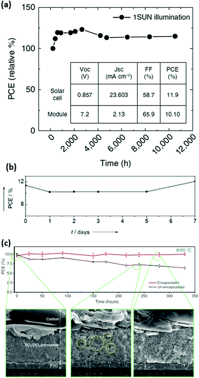 | ||
| Fig. 7 (a) Long-term stability measurement of carbon-based perovskite solar cells and 10 × 10 cm2 modules with IV-parameters shown in the inset. (b) Outdoor stability tests of a HSL-free C-PSC in Jeddah, Saudi Arabia. (c) Thermal stability measurement of encapsulated and non-encapsulated 10 × 10 cm2 modules with SEM images right after the encapsulation and after thermal stress. Adapted and reproduced with permission from ref. 112, 109 and 118. | ||
In addition, Li et al. have conducted for the first-time extensive stability tests under outdoor conditions with increased temperatures (Fig. 7b) and long-term light soaking as well as thermal stress at 80–85 °C during 3 months on the carbon-based HSL-free perovskite solar cells.109 Remarkably, the device performance does not present significant degradation under those stability test conditions, providing a promising pathway towards stable perovskite solar cells with carbon contact. Emami et al. have implemented a laser-sealed glass-frit encapsulation on the C-PSCs which allowed for the cells to withstand damp-heat and thermal cycling tests (although they were carried out for less than 1000 h).115 Wu et al. have also conducted damp-heat tests on the non-encapsulated C-PSCs, where the authors observed that such cells are able to retain 77% of the initial PCE after such an intensive test.116 Furthermore, due to the ease of carbon-based electrode deposition, large sized modules of 70 cm2 have been fabricated, showing an extraordinary stable performance of perovskite modules even in humid environments.117 More recently, by encapsulating carbon-based HSL-free printable PSC submodules (substrate area 100 cm2) with polyurethane (PU) at a mild temperature of 80 °C, the thermal stability of the cell was dramatically enhanced.118 The submodules can still maintain over 97% of the initial PCE after over 2000 h under outdoor conditions (Fig. 7c), which provides potential for commercial viability of the carbon-based perovskite solar cells with excellent stability under suitable encapsulation. As clearly shown in these reports, in comparison to devices with metallic electrodes, carbon-based cells show very stable operation, providing strong arguments for it to be used as a stable back contact in perovskite solar cells and modules.
We have mentioned some of the reported stability tests in the literature on C-PSCs and conventional PSCs in Table 1 for comparison. From these results, it can be observed that most of the reported C-PSCs remain stable under an ambient environment without encapsulation for over 1000 h, whereas the conventional devices with metallic electrodes remain stable in most cases only when they are encapsulated or measured under an inert gas atmosphere. However, to the best of our knowledge, so far there has been no systematic study performed comparing the cell stack with a carbon-based back-contact versus a metallic one in terms of stability (thermal, humidity, oxygen etc.) under the exact same conditions. We would like to invite researchers in the perovskite community to address this issue and quantitatively compare the precise effect of applying a carbon-based electrode instead of metallic ones on the stability of PSCs.
| Device structure (perovskite) | Champion cell PCE (%) | Ageing conditions | Relative PCE retained after ageing (%) | Duration | Ref. | |
|---|---|---|---|---|---|---|
| PSCs with metallic electrodes | ITO/NiOx/PVSK/LiF/C60/SnO2/Ag (FA0.83Cs0.17PbI2.49Br0.51) | ∼14 | Encapsulated, damp-heat test (85 °C, RH = 85%) | ∼99 | 1000 h | 103 |
| ∼14 | Encapsulated, dry-heat test (85 °C, RH = 25%) | ∼97 | 1000 h | |||
| ∼14 | Encapsulated, thermal cycles (−40 to 85 °C) | ∼103 | 200 cycles | |||
| ∼11 | Non-encapsulated, N2 atmosphere, 85 °C | ∼80 | 1000 h | |||
| ∼12 | Encapsulated, N2 atmosphere, 85 °C | 97 | 1000 h | |||
| ITO/SnO2/PVSK/PTAA/NiOx/Au/PEN (Cs0.1(MA0.17FA0.83)0.9PbI0.83Br0.17) | 14.6 | Laminated, 25 °C, continuous MPP-tracking | ∼100 | 93 h | 172 | |
| FTO/NiOx/PVSK/PCBM/BCP/Cr/Cr2O3/Au ((FA0.83MA0.17)0.95Cs0.05Pb(I0.9Br0.1)3 with BMIMBF4) | 19 | Non-encapsulated, RH = 40–50%, 60–65 °C | 86 | 100 | ||
| Encapsulated, 70–75 °C | 95 | 1885 h | ||||
| ITO/NiOx/PVSK/PCBM/BCP/AZO/Ag/Al2O3 (Cs0.05MA0.95PbI3) | 18.45 | Non-encapsulated, 1 sun illumination with UV filter, 85 °C | 86.7 | 500 h | 88 | |
| m-TiO2/PVSK/CuSCN/rGO/Au ((FA1−xMAx)0.95Cs0.05PbI3−xBrx) | 20 | 1 sun illumination with UV filter, N2 atmosphere, 60 °C | 95 | 1000 h | 98 | |
| m-TiO2/PVSK/spiro-OMeTAD/Au ((5AVA)1−xMAxPbI3) | 14.6 | 1 sun illumination, under Ar atmosphere | 60 | 300 h | 112 | |
| PSCs with HTCB-electrodes | m-TiO2/ZrO2/C ((5AVA)1−xMAxPbI3) | 11.4 | Encapsulated, at 80–85 °C, dark | 92.5 | 3 months | 109 |
| Encapsulated, outdoor illumination, non-continuous measurement | ∼105.2 | 7 days | ||||
| m-TiO2/ZrO2/C ((5AVA)1−xMAxPbI3) | 12.7 | Encapsulated, Indoor, 1 sun illumination with UV filter | ∼115 | 10![[thin space (1/6-em)]](https://www.rsc.org/images/entities/char_2009.gif) 000 h 000 h |
112 | |
| m-TiO2/ZrO2/C ((5AVA)1−xMAxPbI3) | 10.74 | Non-encapsulated, indoor, 1 sun illumination | >95 | 2000 h | 117 | |
| m-TiO2/ZrO2/C ((5AVA)1−xMAxPbI3) | 12.8 | Indoor, 1 sun illumination | ∼100 | 1008 h | 32 | |
| m-TiO2/ZrO2/NiO/C (MAPbI3) | 14.9 | Non-encapsulated, dark | >93 | 1000 h | 136 | |
| Non-encapsulated, dark at 60 °C | 79.7 | 1000 h | ||||
| m-TiO2/ZrO2/C (MAPbI3 (MA0-liquefied)) | 15.9 | Non-encapsulated, RH = 55–75%, dark | ∼100 | 3500 h | 173 | |
| m-TiO2/Al2O3/NiO/C (Cs0.05(FA0.4MA0.6)0.95PbI2.8Br0.2) | 17.02 | Encapsulated, at 85 °C, dark | 91 | 1000 h | 137 | |
| m-TiO2/ZrO2/C ((5AVA)0.05MA0.95PbI3) | ∼11 | Encapsulated, damp-heat test (85 °C, RH = 85%) | 100.9 | 50 h | 115 | |
| ∼11 | Encapsulated, thermal cycles (−40 to 85 °C) | 97.7 | 70 cycles | |||
| ∼11 | Encapsulated, RH = 80%, dark | ∼110 | 500 h | |||
| PSCs with LTCB-electrodes | m-TiO2/PVSK/CuPc/C (MAPbI3) | 16.1 | Non-encapsulated, dark | 91.5 | 600 h | 142 |
| SnO2@TiO2/PVSK/P3HT-graphene/C (FA0.3MA0.7PbI3) | 18.1 | Non-encapsulated, RH = 50%, dark | 97 | 1680 h | 146 | |
| Encapsulated, 1 sun illumination without UV and IR, indoor | 89 | 600 h | ||||
| Ni:TiO2/PVSK/CuPc/C (Cs0.05(FA1−xMAx)0.95PbI3−xBrx) | 17.46 | Non-encapsulated, RH = 30–40%, dark | 97 | 1200 h | 157 | |
| m-TiO2/PVSK/spiro-OMeTAD/C (FA1−xMAxPbI3−xBrx) | 19.2 | Non-encapsulated, RH = 30%, dark | 95 | 1000 h | 114 | |
| Zn:SnO2/PVSK/CuPc/C (Cs0.05(FA1−xMAx)0.95PbI3−xBrx) | 17.8 | Non-encapsulated, RH = 20%, dark | 100 | 1200 h | 113 | |
| m-TiO2/PVSK/TPDI/C (MAPbI3) | 15.5 | Non-encapsulated, outdoor illumination | 82.6 | 30 days | 140 | |
| SnO2/PVSK/spiro-OMeTAD/C/graphite paper (Cs0.05(FA0.85MA0.15)0.95PbI2.55Br0.45) | 18.56 | Non-encapsulated, dark | >90 | 1500 h | 174 | |
| FTO/m-TiO2/PVSK/PEO/C (FA0.8Cs0.2PbI2.64Br0.36) | 14.9 | Non-encapsulation, damp-heat test (85 °C, RH = 85%) | 77 | 192 h | 116 | |
2.2. Low-cost
Perovskite PV has a chance to be a disruptive technology, promising low fabrication costs and therefore final product price. However, several studies have revealed that material and processing costs of metal electrodes like gold and HSLs (e.g. spiro-OMeTAD and P3HT) as currently employed in many laboratory-scale devices together with the TCO account for the highest costs in the total module price. To decrease the cost further, this mandates to either reduce the usage of these materials or to replace them with cheaper alternatives.According to a report by Chang et al., in devices with evaporated Au-electrodes, more than 90% of the total device costs are attributed to material costs, 76.6% of which come from gold, contributing to 74.7% of the total fabrication costs (including materials, evaporation process etc.).119 The authors estimated the cost of a module of FTO/c-TiO2/m-TiO2/Perovskite/P3HT/Au to be around 330 $US m−2, which was significantly more expensive than the CdTe (86 $ m−2) and c-Si (136 $ m−2) modules at that time (in 2017). In addition, the study suggested that replacing Au with Ag would decrease the price to a comparable value of 102 $ m−2 or it can even be reduced to 90 $ m−2 if one avoids using a sacrificial metal mask during spray deposition of c-TiO2 and uses laser patterning instead.
The cost of roll-to-roll manufactured flexible perovskite PV devices has also been investigated by Chang et al. in a later report. They found that using screen-printing for back contact metallization strongly reduces the capital costs of the final module, in comparison to metal evaporation deposition.120 Considering that with higher web-speeds the manufacturing costs decrease, the material costs become more and more dominant in the total module fabrication costs. Therefore, cheaper HSLs and back-contacts such as carbon-graphite are vital for the further reduction of the module price in industrially relevant high/throughput fabrication methods.
Song et al. have investigated the material and manufacturing costs of industrially fabricated modules with inorganic selective layers and Al back electrode in a p–i–n configuration.121 Notably, the authors found that depositing such inexpensive materials by industry-scale deposition techniques (screen-printing and sputtering) leads to very low material costs of the functional layers of a PV device (ESL, perovskite, HSL), accounting for only 1.1% of the total material cost of a module. Interestingly, when the employed functional layers are so low-priced, 93.5% of the total material costs come from the balance of the system/module, which includes glass substrates, interconnection busbars, sealant, lamination film, edge-sealing frame, a junction-box and wiring. These results show that using up-scalable deposition techniques for fabricating back-electrodes results in reasonable module prices (unlike evaporation of noble metals), which serves as a further motivation towards printable PSCs with carbon-based contacts, due to higher long-term stability than the metal-based ones.
All of the studies mentioned above have been conducted via a bottom-up cost calculation approach, which considers the cost and its uncertainty at each manufacturing step.120 In summary, we postulate that in order to reach perovskite module prices lower than that of c-Si or thin-film technologies, one needs to implement low-cost materials, which can be easily applied on an industrial scale. An example of such module cost reduction may be replacement of the metal electrode with a carbon-based contact in a perovskite PV device stack.
2.3. Up-scaling
An increasing number of companies, such as Microquanta Semiconductor, Saule Technologies and Toshiba, have recently started to develop large-scale single-junction perovskite PV modules.122 However, for the large-scale applications it is still challenging to accurately control layer deposition to form homogeneous pin-hole-free films.20 Most of the record-breaking perovskite solar cells or modules utilize a metal evaporation step in the device fabrication process, which requires high vacuum conditions, making it difficult and costly to upscale, in addition to the high CO2 footprint of such modules. Carbon pastes can be solution-processed with a variety of fast, large area-compatible, and low-cost deposition techniques. Moreover, low-temperature pastes (which will be discussed in Section 3) can be processed on top of the perovskite photovoltaic stack, which makes these materials one of the most up-scalable back contact electrode options for perovskite technology.Over the last few years multiple large-area perovskite PV modules utilizing carbon electrodes were reported. In 2016, Priyadarshi et al. reported carbon-based PV modules yielding 10.74% PCE (70 cm2 active area) and good ambient stability (less than 5% drop over more than 2000 h).117 Subsequently, Grancini et al. demonstrated 11.2% PCE for the perovskite module of the same architecture (47.6 cm2 active area out of 100 cm2 module area).112 Already in 2016, the swiss-based company Solaronix demonstrated an HSL-free 500 cm2 carbon-based perovskite module with a PCE of 12%, produced by a drop-casting method.122 Recently, Xu et al. reported modules with an area of 60.08 cm2, having PCE of 12.87%, infiltrated with perovskite solution using slot-die coating.123 The group of Hongwei Han from Huazhong University of Science and Technology showed large-area perovskite solar panels of 7 m2, which were fully fabricated with printing techniques.118 Weihua Solar, a Chinese perovskite PV manufacturer, demonstrated a power station made out of 32 carbon-based, perovskite panels of 45 × 65 cm2 area.124 Cai et al. printed carbon back contact on top of a perovskite layer, delivering 10.6% PCE for the HSL-free architecture (FTO/ZnO/MAPbI3 perovskite/Carbon), with an active area of 17.6 cm2 (module area: 5 × 5 cm2).124
These examples highlight significant progress in the scalable manufacturing of carbon-based perovskite PV modules, and big potential for large-scale industrial deployment.
2.4. Sustainability: CO2-footprint and resource consumption
The motivation behind the development of every renewable energy generation has been mainly attributed to decreasing green-house-gas emissions (e.g. CO2, CH4) and preventing the depletion of fossil energy sources. Therefore, even though the CO2-footprint of the photovoltaics is much lower than that of fossil fuel energy generation, based on global PV installation projections until 2050, the total CO2-emissions from Si PV manufacturing could have a substantial share on global greenhouse gas emissions.125 Such projection displays how crucial it is to continuously develop the PV sector, aiming at technologies with lower CO2 footprint.Soon after perovskite PV emerged as a booming research field, there have been several extensive life-cycle assessments of perovskite solar cells.126–128 The authors found that among the manufacturing processes of each cell layer, the primary energy consumption of cathode evaporation is the highest and Au has the highest embedded energy – the energy required to extract this material from the ore. More importantly, the gold cathode has the highest impact on the environmental profile of the cell (Fig. 8) and its replacement would greatly reduce the environmental harm during the PSC manufacturing process. Notably, a recent study conducted by our group revealed that the CO2 footprint of some high-temperature carbon-based perovskite modules can be as low as 4.7% of that of c-Si PV modules.125 In addition to the scarcity of noble metals, it is strongly suggested that, to minimize the environmental impact of perovskite PV, another type of cathode material that can be deposited with less energy consumption needs to be developed, such as carbon-based electrodes.
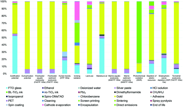 | ||
| Fig. 8 Environmental profile of 1 m2 FTO/c-TiO2/m-TiO2/MAPbI3/spiro-OMeTAD/Au perovskite PV device. Adapted and reproduced with permission from ref. 126. | ||
For a truly sustainable global society, a circular economy needs to be implemented where resources are not lost, but recycled or based on renewable sources. Metals are a group of materials well-suited for recycling. However, their recycling efficiencies are governed by the second law of thermodynamics,129,130 where the created entropy across the chains of circular economy dictates the inevitable energy losses. Especially for highly technological electronic devices, this implies that fine distributions of different materials such as a hundred nanometer thin metal back electrode of a perovskite solar module inevitably leads to dissipation and thus loss of at least a part of these metals from the circular economy. Graphite, although today mainly extracted from fossil resources, can already be produced from renewable, plant-based resources such as coconut shells131 and aloe vera.132
One step towards designing a more sustainable energy harvesting technology can be reached by replacing the metal back electrode with a stable, organic matter-based materials like graphite.
3. High-temperature carbon vs. low-temperature carbon
Carbon electrodes in perovskite solar cells can be prepared through two main routes: high- and low-temperature curing (Fig. 9). A typical high-temperature carbon-based (HTCB) cell is fabricated by depositing mesoscopic selective and electrode layers, which are usually printable (e.g. by screen-printing) and require high-temperature pyrolysis of the organic binders and solvents in them. Therefore, a processing temperature of 400–500 °C during layer deposition is needed,133 meaning that perovskite precursor solution can be only added afterwards.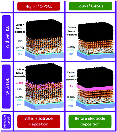 | ||
| Fig. 9 Schematics of perovskite solar cells with high- and low-temperature carbon-based electrodes with and without HSL. | ||
On the other hand, in low-temperature carbon-based (LTCB) cells, the electrode layer is fabricated at temperatures below the irreversible perovskite degradation, allowing for the deposition of perovskite before the back-electrode.
Both strategies can be implemented with or without HSL. However, as will be noted later in this work, the LTCB-cells allow for an easier integration of the HSL than the high-temperature treated ones.
3.1. Cell structures
The overall structure of a typical HTCB-cell without a hole-selective layer consists of a front FTO/Glass substrate, a mesoporous inorganic electron-selective layer, an insulating layer and a mesoporous HTCB-electrode. In order to improve the efficiency by avoiding non-radiative recombination at the front-electrode, a compact hole-blocking layer (e.g. c-TiO2) has proven to be essential for reaching high PCEs.
Emerging from the dye-sensitized solar cells, an anatase mesoporous TiO2 layer has been widely used as an electron-selective layer not only in the traditional mesoscopic n–i–p cells,30,134 but also in HTCB-cells. The insulating layer was found to be crucial, in order to avoid ohmic shunts via contact between the counter electrode and front electrode or ESL. Metal oxides with suitable valence and conduction bands are commonly employed as ESLs and insulating layers in HTCB-cells. Porous dielectric oxide layers of ZrO2 and Al2O3 have been mainly used as insulators, due to their ability to avoid direct shunts and inability to extract charge carriers.31,33 Sputtered layers of Al2O3 as thin as 10 nm, which can also electrically isolate electrons in the conduction band of m-TiO2 from reaching the back-contact and the respective electrodes against pin-holes to the TCO layer have been demonstrated by us earlier.135 The latter advantage is particularly useful for large-area device fabrication, to avoid the shunted regions in the modules. Because of the nature of the sputtering process, the inner surface (i.e. inside the pores) of the m-TiO2 is not covered and therefore accessible for electrons extracted from the perovskite.
After the insulator layer is fabricated, the mesoporous cell stack is completed by depositing a HTCB-layer and drop-casting the perovskite solution. The concept of a fully-printable triple-layer carbon-based (TiO2/ZrO2/Carbon) perovskite solar cell (Fig. 9) has gained wide attention after Mei et al. displayed an exceptional stability and strong upscaling potential of such devices.32 Since then, the development of such HTCB cells has been rapid, resulting in an extensive list of reports demonstrating large area devices with moderate efficiencies. In 2018 a company called Wonder Solar launched a 110 m2 PV system based on a triple-layer architecture.20 Also a double-mesoscopic layer structure was proposed by replacing the thick porous spacer layer with a sputtered ultra-thin pseudo-porous Al2O3 layer.135 However, the absence of hole-selective contacts in such PV devices results in excessive surface recombination at the counter electrode and limits the open-circuit voltage of the device.133 To overcome this issue in HTCB-cells, Xu et al. proposed to use a mesoporous NiOx layer as a hole-selective material.136 The HTCB-cells with TiO2/NiOx/Carbon layers have been found to have a slightly higher PCE than that of the standard triple-layer configuration, but the strong recombination at the TiO2/NiOx interface poses a problem for reaching high efficiencies in such devices.136 In fact, the highest reported PCE of 17.02% (non-certified) for the HTCB-cell to date was achieved by Liu et al. via integration of mixed absorber Cs0.05(FA0.4MA0.6)0.95Pb2.8Br0.2 into the TiO2/Al2O3/NiOx/Carbon structure (mesoscopic cell with HSL, as well as J–V and EQE measurements are shown in Fig. 10). Although, the Voc in these cases was still below 1.01 V, highlighting that the implementation of NiOx (as a mesoporous or thin layer) into the C-PSCs is still an ongoing research topic. Apparently, there is still large room to further improve the efficiencies of these devices; however, it is limited by the compatibility of HSLs with the sintering process of such mesoscopic structures under high temperatures.
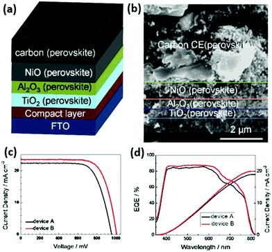 | ||
| Fig. 10 (a) Schematic cell architecture of the HTCB-cell with the highest PCE reported to date. (b) Cross-section SEM image of the device. (c) IV curves of the devices with such architecture, including different absorbers: device A – FA0.4MA0.6PbI2.8Br0.2, device B – Cs0.05(FA0.4MA0.6)0.95PbI2.8Br0.2. (d) External quantum efficiency and integrated current density of devices A and B. Adapted and reproduced with permission from ref. 137. | ||
After the deposition of hole-blocking layer and ESL, the perovskite photoabsorber layer is deposited straight away.31 In contrast to high-temperature processed cells, here perovskite can have large crystals, that are not constrained by the pore size as in a triple-layer porous structure. Also, it provides a wide range of opportunities for solvent engineering and crystallization control techniques that are often challenging in the cells with a HTCB-electrode.31 When the perovskite layer is crystallized, the carbon layer completes the HSL-free cell architecture, followed by mild annealing (in most cases <120 °C).
In the cells where the hole-selective layer is present it can be added either as a dense film between the perovskite and carbon (before electrode deposition) or it can be added directly to the LTCB-paste prior to the paste manufacturing process.138 In the latter case, the HSL is formed directly at the perovskite/carbon interface upon the curing process of the electrode.
3.2. Key advantages of the low-temperature processed electrodes
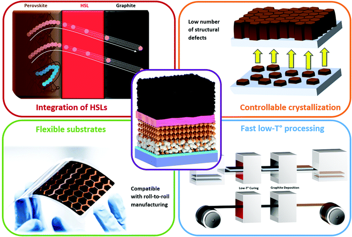
The low-temperature C-PSC concept has several important advantages depicted in Fig. 11 in comparison to the high-temperature one, such as ability to easily integrate a planar hole-(or electron-) selective layer, a higher control over the perovskite crystallization, compatibility with flexible substrates and higher processing speed, without requiring high-temperature sintering.In the state-of-the-art PSCs, the organic HSLs with suitable valence bands are implemented, although, the drawback of this strategy is the layer stability. As mentioned before, there are few choices of materials which do not have a hygroscopic nature, do not degrade perovskite and meet the demands of high hole mobility and suitable valence band. Nevertheless, a lot of research in the past few years was focused on improving the cell efficiency by the introduction of HSLs described below.
According to a recent report from Ren et al., a layer of fluorinated small molecules based on difluorobenzene, benzo[1,2-b:4,5-b′]dithiophene (BDT) and 4,4′-dimethoxydiphenylamine (DPA) – BDT2FMeDPA can be used as a dopant-free hydrophobic HSL. In particular, the authors have deposited this novel HSL in between the perovskite and LTCB-electrode achieving PCE of 14.5%, keeping 90% of the initial value after 30 days.139 As an alternative HSL with improved thermal stability, hole mobility, valence band alignment and cost-effectiveness, a 5,10,15-triphenyl-5H-diindolo[3,2-a:3′,2′c]carbazole (TBDI) was proposed.140 Implementation of this layer resulted in reduction of the perovskite/carbon interface energy barrier, comparable PCE with cells containing spiro-OMeTAD and a much higher stability. Deposition of PEDOT:PSS in cells with an LTCB-electrode appears to improve this contact, thereby decreasing the hysteresis.141
Integration of copper phthalocyanine (CuPc) nanorods as the HSL in the LTCB-cell (Fig. 12a) yielded a similar hole-extraction ability to spiro-OMeTAD and decreased charge carrier recombination at the back electrode, resulting in an impressive PCE of 16.1%.142 A commonly used electron-donor layer in organic PV – poly(3-hexyl thiophene) (P3HT), has also been employed as an HSL, not only in standard PSCs, but also in LTCB-cells.143–145 By adding graphene to the pristine P3HT (Fig. 12b), Chu et al. were able to enhance the hole mobility of the HSL by almost two orders of magnitude.146 With the help of this composite P3HT/Graphene layer, the authors reported an outstanding certified efficiency of the LTCB-cell, which is the highest at the moment for C-PSCs – 17.8%.
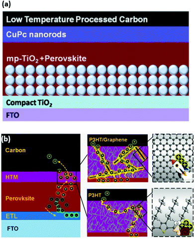 | ||
| Fig. 12 (a) Schematic structure of the LTCB-cell with CuPc nanorods as the HSL. (b) Schematic structure of the LTCB-cell with P3HT as the HSL (HTM), illustrating how incorporation of graphene results in higher hole mobility and better charge transport. Adapted and reproduced with permission from ref. 142 and 146. | ||
Another inorganic HSL that has been often exploited in perovskite and dye-sensitized solar cells, CuSCN, has been implemented by Baranwal et al. to enhance the FF and slightly improve the Voc of LTCB-cells.110 However, it was found that over a long time, degradation at the CuSCN/perovskite interface occurs, mediated by the loss of SCN group, leading to an interdiffusion between the perovskite and HSL. A similar result on the poor long-term stability of the pristine CuSCN/perovskite interface was also noted by Arora et al.98
Several studies have highlighted the enhanced hole-extraction and reduced recombination at the back electrode of HTCB-cells by addition of mesoporous NiOx into the cell stack.136,137,147,148 Peiris et al. have demonstrated how an LTCB-electrode can be applied on top of a fully-printed m-TiO2/ZrO2/NiOx stack with a minimized perovskite capping layer via N2 blow drying.149 Although, planar NiOx, which is often used in p–i–n and n–i–p PSCs with a metal electrode, can also be implemented in LTCB-cells, there were no reports of such cell configuration, according to our knowledge.
An example of carefully controlled crystallization in LTCB-cells was given by Chen et al., who obtained an outstanding result of 14.38% PCE with a Voc above 1 V on 0.07 cm2 active area and 10% PCE on 1 cm2 devices.151 The high-quality perovskite film was obtained via a 2-step approach, where the solvent of MAI in the second step was changed from isopropanol (IPA) to a mixed solvent of IPA/Cyclohexane (CYHEX) (Fig. 13). This mixed-solvent strategy has been proved not only to accelerate the conversion of PbI2 to MAPbI3, but also to effectively suppress the Ostwald ripening process, which eventually provided a pure high-quality perovskite layer with a uniform surface and compact capping layer structure.151 The similar method of solvent engineering was realized later by the same group to deposit a more thermally stable MAPbBr3 perovskite through the addition of non-polar CYHEX into the second step solvent of IPA, leading to a LTCB-cell with a PCE of 8.09%.152 In addition, the perovskite composition with a mixed cation of methylammonium (MA) and formamidinium (FA) has been explored by Bai et al. in order to enhance the light harvesting capability. The synthesized cubic: column composite structure of (FA)x(MA)1−xPbI3 has been demonstrated to broaden the light harvesting area and reduce the probability of electron recombination.153
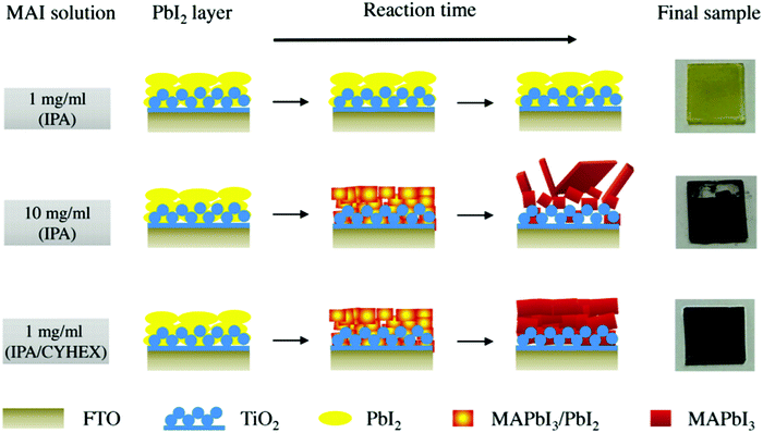 | ||
| Fig. 13 Illustration of crystallization dynamics where MAI in IPA and augmented IPA/CYHEX mixed solvents are added to the PbI2 layer. Adapted and reproduced with permission from ref. 151. | ||
Furthermore, in 2016, Chang et al. implemented a colloidal engineering approach, where the authors controlled the crystallization via formation of PbI2(DMSO)-adducts dispersed in DMF (Fig. 14).154 The resulting film shows an impressive perovskite layer homogeneity, leading to a better interfacial contact at the perovskite/carbon interface. The renowned anti-solvent engineering techniques, which are widely used nowadays to prepare high-quality dense perovskite crystals,150 have also been realized in LTCB-cells, by adding chlorobenzene during the precursor deposition process.155 Zhou et al. have demonstrated how the incorporation of amino-group functionalized ionic liquid to the precursor solution, yields highly crystalline perovskite with large grains and hydrophobic surface, promoting even higher stability in HSL-free LTCB-cells.156 As can be seen from multiple reports on the topic, the mixed-cation, mixed halide hybrid perovskite films with high crystallinity can be easily manufactured in LTCB-cells,113,114,146,157 since the processing conditions are identical to conventional cells with metallic electrodes, which provides a strong foundation for C-PSCs reaching high PCEs. C-PSCs with inorganic CsPbBr3 perovskite, having an LTCB-electrode were reported as well, which had an outstanding stability in a humid environment (90–95% RH) for over 3 months, in addition to stable performance even under harsh temperature conditions (100 °C to −22 °C).158 By introducing small amounts of Sn into the perovskite structure, Liang et al. fabricated mixed CsPb0.9Sn0.1IBr2 all-inorganic perovskite solar cells, covered with an LTCB-electrode, which exhibited an impressive PCE of 11.33%.159 LTCB-cells with a Mn-doped all-inorganic perovskite absorber have also been reported, displaying a moderate stability, thanks to the inorganic nature of the perovskite and stable LTCB-electrodes.160 In addition to all these crystallization-controlling techniques, which were already applied in LTCB-cells, many more effective methods coming from traditional PSCs with metal electrodes can be implemented. We also note that passivation and interface engineering plays a crucial role in enhancing the PCE and stability can also be easily realized in cells with LTCB-electrodes, as was recently demonstrated by Di Carlo et al.161
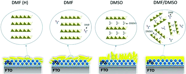 | ||
| Fig. 14 Illustration of the role of DMF and DMSO solvents in the crystallization and how PbI2(DMSO) adducts dispersed in DMF yield a superior film morphology. Adapted and reproduced with permission from ref. 154. | ||
Using this advantage of low-temperature processing, Zhou et al. have applied this layer on a flexible substrate showing potential for producing flexible PSCs with a hydrophobic carbon-based electrode.107 In manufacturing flexible PSCs, mechanical integrity after multiple bending cycles is an important consideration. Wang et al. have tested the durability of their LTCB-cell and showed that it could keep 70% of its initial PCE even after 1000 bending cycles (Fig. 15).141
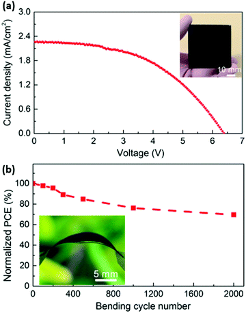 | ||
| Fig. 15 (a) J–V curve of the as-prepared flexible 5 × 5 cm2 LTCB-minimodule. (b) PCE change of the LTCB-minimodule after multiple bending cycles (photograph of the minimodule in a bent state is shown in the inset). Adapted and reproduced with permission from ref. 138. | ||
To date, there are few published studies of carbon-based PSCs on flexible substrates. Chu et al. fabricated LTCB-cell (n–i–p configuration) with graphene-doped P3HT as the HTL.146 The devices on PEN foil delivered an efficiency of 12.4% with only 3% drop after storage under ambient conditions (humidity: ca. 50%) for 1680 h. Recently, Babu et al. demonstrated carbon-based flexible perovskite solar cells in the p–i–n configuration on PET foil.163 The devices with an active area of 1 cm2 delivered an efficiency of 15.18% and excellent operational (MPPT) and thermal (85 °C) stability over 1000 h of ageing.
In one of the studies by integrating copper phthalocyanine (CuPc) as an interface modifier and dopant, He et al. demonstrated an LTCB module with an active area of 22.4 cm2. The module retained 75% of its initial PCE of 6% after 2000 bending cycles.138
One of the key problems of flexible PSCs is the use of expensive conductive metal oxides, such as ITO, which significantly hinders the full commercialization potential. In other thin-film technologies, the front-contact materials such as Al-doped zinc oxide (AZO) and thin transparent Ag are not chemically compatible with perovskite in the long-term. Therefore, we suggest that cheaper and long-term stable alternatives (e.g. using titanium foil164 or “wrap-through” concept165) for transparent front-contact are essential for the development of flexible PSCs.
3.3. Low-temperature carbon-based electrodes offer to close the efficiency gap between G-PSCs and traditional cells
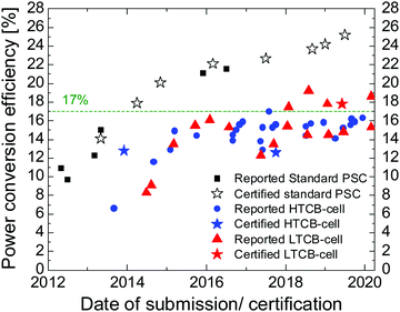
To date most of the high-efficient HTCB-cells have open circuit voltages around 1 V,135,137,170,171 despite tremendous efforts to boost this value closer to the cells with HSL and the metallic electrode. In contrast, the versatility of implementation of the LTCB-layer is the most attractive advantage of this approach, as the layer can be simply used to replace the costly metal-based electrodes on top of the HSL to improve cell stability at low cost.As mentioned earlier, the multiple crystallization control and passivation techniques, which were implemented in traditional PSCs, can also be applied here, which can allow growth of high-quality crystals with less grain boundaries as well as less structural and electronic disorder. In addition, implementing selective layers in LTCB-cells with high carrier-mobilities and favorable band alignment will provide much higher PCEs than the standard HTCB-cells can offer. One can notice from Table 1 and Fig. 16 that since 2018 LTCB-cells went beyond 17% PCE (with 17.8% certified PCE), bridging closer to the record-breaking cells with metallic electrodes. Therefore, replacing metal electrodes with more moisture-resistant and chemically stable low-temperature carbon-based electrodes is the most promising route to mitigate the efficiency gap between standard perovskite cells and carbon-based ones.
4. Low-temperature carbon paste composition
The composition of the carbon paste plays an important role in the device performance and stability of the carbon-based perovskite soar cells. Typically, the composition of carbon paste includes carbon-based materials, organic solvents or/and organic binders in different ratios, which could be deposited by solution processable methods, such as doctor-blading and screen printing.133 Carbon black, graphite, graphene and carbon nanotubes are commonly used materials for carbon paste. Wei et al. have shown that a carbon-based electrode composed of pure carbon black particles deposited by the “candle soot” method can be employed as the counter electrode for PSCs yielding an impressive PCE of 11.02%.175 In order to further improve the conductivity of the carbon electrode, in further studies graphite was introduced to the carbon paste to reduce the resistive losses. High conductivity of graphite is associated with a high number of delocalized π electrons, meaning that increasing the graphite content in the layer decreases its sheet resistivity.176 Ku et al. have shown how the graphite shape (e.g. spheroidal, flaky) affects the photovoltaic properties of the solar cell devices.29 To make the resulting electrode more porous, normally carbon black particles are added to the carbon paste, which creates space between the flakes.33 The main roles of carbon black particles are to adjust the paste processability and facilitate an efficient interconnection between graphite flakes177 as well as between the perovskite layer and graphite flakes.178In order to form a continuous electrode layer, an organic binder such as ethyl cellulose is normally used.176 Since such a binder has to be removed before the introduction of perovskite solution into the cell layers, the carbon-based layer has to be sintered at temperatures over 400 °C. This introduces a serious obstacle for the traditional layer-by-layer deposition method that is predominant in the perovskite community. Therefore, in high temperature carbon-based cells, the perovskite solution is drop-casted on the monolithic cell stack after all the functional layers are manufactured and sintered. This highlights that the porosity of the carbon-based electrode (enhanced by carbon black particles) is essential for allowing the complete cell infiltration with solution. Once the cell is impregnated with it, the annealing removes the solvent, causing the crystallization of perovskite inside the cell stack.
Since the low-temperature carbon-based layer, a priori does not need to be annealed at high temperatures to remove the binder, it can be deposited on top of perovskite or charge-selective layer directly. The paste in this case can be composed of carbon powder, a moderate solvent and curing resin or a binder that can be annealed at temperatures less than the decomposition temperatures of HSL and perovskite. Zhou et al. demonstrated how a simple dispersion of dried carbon powder (obtained from commercial paste) with a small portion of ZrO2 particles can be dispersed in chlorobenzene to produce an LTCB ink.107 A similar approach was later implemented by Gholipour et al. except for the absence of ZrO2 particles.111 Liu et al. have produced an LTCB paste using carbon powder, and polyvinyl acetate (PVAc) as a binder with a small portion of hydroxypropyl cellulose to adjust the viscosity of carbon paste, which were dispersed in ethyl acetate.179 Dileep et al. implemented carboxy-methylcellulose, which could be used as a low-temperature curable binder.176 Adding a carbon powder, they were able to get a paste curable at room temperature. Recently, Han's group has successfully developed an LTCB paste, with the help of titanium(IV) isopropoxide and acetic acid acting as low-temperature binders dispersed in terpineol.180 The peculiar interaction between the binders was attributed to the separation of the acetate group from acetic acid and formation of ligands with Ti4+ in bidentate and bridging binding modes. The resultant polymeric Ti–O–Ti species encapsulate the graphite and slightly permeate carbon-black particles, producing a strong inter-particle connection, responsible for the layer robustness and conductivity. The resulting LTCB-layer showed an exceptionally low sheet resistance, even lower than that of an HTCB-layer. The same group later demonstrated how such paste can form cracks on top of a perovskite layer after deposition, unless an anti-solvent like chlorobenzene is dripped upon the cell.141 Later the cell can be annealed at 100 °C for 20 min to completely evaporate chlorobenzene.
Zhang et al. have implemented a solvent-exchange process, shown in Fig. 17, where ethanol was added to the paste in order to suppress excessive curing to avoid densification of the carbon-film.114 However, since ethanol can partially dissolve perovskite (but not PbI2), the carbon layer had to be transferred on top of the cell layers by a press-transfer technique using another substrate. A notable perovskite-friendly approach has been proposed by Chu et al., where the authors produced their LTCB-paste based on propylene glycol monomethyl ether acetate (PGMEA) and polyacrylic resin binder and directly applied it on the perovskite layer.171
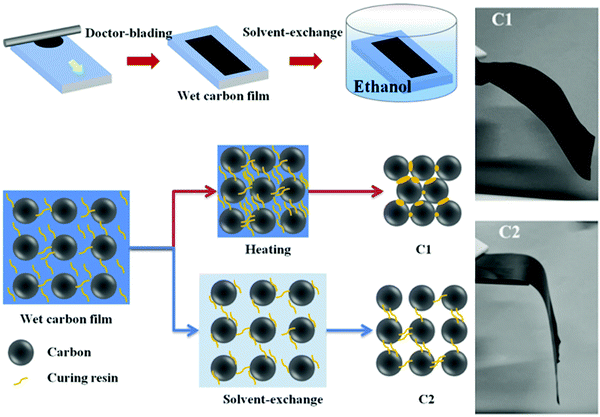 | ||
| Fig. 17 Schematic diagram of room-temperature solvent-exchange (C2) LTCB-electrode preparation vs. the standard low-temperature annealing method (C1). Photographs of the differences in mechanical flexibility between both preparation methods. Adapted and reproduced with permission from ref. 114. | ||
This myriad of different LTCB-paste compositions shows that there are a lot of alternative routes to produce high quality and conductive pastes through composition engineering, giving a large space for researchers in the perovskite community to explore.
5. Deposition methods of low-temperature carbon-based electrodes
The reported deposition techniques of low-temperature carbon-based electrodes, based on liquid processing include: blade coating, press transfer and screen printing. Despite high potential of slot-die coating for large area films, there were no perovskite solar devices with a slot-die coated LTCB-electrode reported, according to our knowledge. Also, since in the past few years most of the record-breaking cells were produced using spin-coating and metal evaporation, less attention was given to the aforementioned up-scalable methods. Naturally, this influenced the rate of development of these strategies, which currently lags behind the conventional ones. Although there have been slightly more reports on HTCB-cells and modules, due to strong advantages of the LTCB-concept discussed earlier (to reach efficiencies comparable to the ones with metal electrodes), we strongly encourage scientists and engineers in the perovskite community to explore this option.5.1. Blade-coating
Blade-coating (or doctor-blading) is an up-scalable layer deposition technique where solution/paste is dropped on a substrate and then spread by sweeping a blade across the substrate at a fixed height. The resulting thin layer can have comparable heights (controllable by blade height and speed) to spin-coating, allowing for swift solvent evaporation and uniform, dense film deposition. This promising technique has the potential to be implemented for LTCB-manufacturing in an ambient environment on a large scale and it is also compatible with roll-to-roll manufacturing.In the first reports on an LTCB-electrode in PSCs, the authors used blade coating to deposit carbon and achieved PCEs of 8–9%.107,140 Over the years, many of the LTCB-electrodes demonstrated in the literature were manufactured this way and remarkable power conversion efficiencies over 17% (Table 2) have been achieved in PSCs.
| Carbon deposition method | Cell structure (perovskite composition) | PCE (%) | Year | Ref. |
|---|---|---|---|---|
| Blade-coating | m-TiO2/PVSK/C (MAPbI3) | 9 | 2015 | 107 |
| Blade-coating | m-TiO2/PVSK/TPDI/C (MAPbI3) | 15.5 | 2015 | 140 |
| Blade-coating | m-TiO2/PVSK/CuPc/C (MAPbI3) | 16.1 | 2015 | 142 |
| Blade-coating | m-TiO2/PVSK/C (MAPbI3) | 12.3 | 2017 | 181 |
| Blade coating | m-TiO2/PVSK/C (MAPbI3) | 13.5 | 2018 | 171 |
| Blade-coating | m-TiO2−SnO2/PVSK/CuPc/C (Cs0.05(MA0.17FA0.83)0.95Pb(I0.83Br0.17)3) | 15.4 | 2018 | 186 |
| Blade-coating | m-TiO2/PVSK/BDT2FMeDPA/C ((FAPbI3)0.85(MAPbBr3)0.15) | 14.5 | 2018 | 139 |
| Blade-coating | Ni:TiO2/PVSK/CuPc/C (Cs0.05(FA1−xMAx)0.95PbI3−xBrx) | 17.46 | 2018 | 157 |
| Blade-coating | m-TiO2/PVSK/CuPc/C (MAPbI3) | 14.8 | 2019 | 138 |
| Blade-coating | Zn:SnO2/PVSK/CuPc/C (Cs0.05(FA1−xMAx)0.95PbI3−xBrx) | 17.8 | 2019 | 113 |
| Press-transfer | m-TiO2/PVSK/spiro-OMeTAD/C (FA1−xMAxPbI3−xBrx) | 19.2 | 2017 | 114 |
| Press-transfer | SnO2/PVSK/spiro-OMeTAD/C/graphite paper (Cs0.05(FA0.85MA0.15)0.95PbI2.55Br0.45) | 18.6 | 2019 | 174 |
| Hot-press | m-TiO2/PVSK/spiro-OMeTAD/C (Cs0.05(FA1−xMAx)0.95PbI3−xBrx) | 15.3 | 2016 | 111 |
| Hot-press | SnO2/PVSK/CuSCN/C (Cs1−x(FA0.83MA0.17)x PbI2.53Br0.47) | 15.3 | 2020 | 182 |
| Screen-printing | m-TiO2/PVSK/C (MAPbBr3) | 8.1 | 2016 | 152 |
| Screen-printing | m-TiO2/PVSK/C (MAPbI3) | 14.4 | 2016 | 151 |
| Screen-printing | m-TiO2/PVSK/PEDOT:PSS/C (Cs0.05(FA0.83MA0.17)0.95Pb(I0.83Br0.17)3) | 14.5 | 2019 | 141 |
| Screen-printing | SnO2/MOH/PVSK/C (CsPbIBr2) | 11.8 | 2019 | 187 |
| Ink-jet printing | m-TiO2/PVSK/C (MAPbI3) | 11.6 | 2014 | 184 |
| Spraying | SnO2/PVSK/spiro-OMeTAD/C-carbon black (Cs0.05(FA1−xMAx)0.95PbI3−xBrx) | 14.1 | 2019 | 185 |
| SnO2/PVSK/spiro-OMeTAD/C-graphite (Cs0.05(FA1−xMAx)0.95PbI3−xBrx) | 9.9 | |||
| SnO2/PVSK/spiro-OMeTAD/C-graphene (Cs0.05(FA1−xMAx)0.95PbI3−xBrx) | 18.7 | |||
Chu et al. have implemented a “fast drying” process (Fig. 18) to show that a blade-coated carbon paste can be dried by mild annealing at 100 °C and exposure to vacuum for a short amount of time.181 Since the paste is directly applied on the cell layer, it should not contain solvents that can dissolve the layers underneath. The speed and pressure applied on top of the blade play a critical role in deposition of homogeneous LTCB-layers with a tight connection to the layers beneath it.
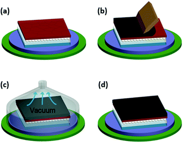 | ||
| Fig. 18 Schematic diagram of the fabrication process of the LTCB-electrode using blade coating and subsequent drying, which can be vacuum-assisted. Adapted and reproduced with permission from ref. 181. | ||
5.2. Press-transfer
Due to the often-occurring issue of poor contact between the perovskite or HSL and carbon electrode, the cells often have high series resistance at the carbon/perovskite or carbon/HSL interfaces. A press-transfer technique has been praised by being able to partially minimize this problem. Additionally, this technique is well-compatible with fast roll-to-roll production. The first step of this method is deposition of an LTCB-layer on a substrate (e.g. by blade-coating) followed by subsequent solvent removal. Then, the substrate with a carbon-based layer is pressed against the remaining cell layers leading to an improved adhesion and interfacial contact.As of today, some of the highest efficiency PSCs with a carbon-based electrode (not only among low-temperature processed ones) have been realized via the press-transfer approach. Zhang et al. proposed an impressive approach – to reduce the number of agglomerated carbon blocks during film curing by a solvent-exchange process instead of common annealing. After removing the solvent in the paste, the LTCB-layer was deposited on top of the cell stack by a press-transfer method. The combination of high film compressibility (thanks to avoidance of carbon-agglomerations) and pressing technique (which improves the interface between carbon and layer underneath) resulted in achieving a record PCE of 19.2%.114 Later, the same group modified their novel deposition method by using a highly conductive transferring substrate in order to successfully implement it on a large area (1 cm2) device, reaching a PCE above 17%.174
The so-called “hot-press” approach (in the context of PSC manufacturing) is a press transfer method carried out at increased temperatures (Fig. 19). Interestingly, Yang et al. have found how applying higher temperatures during the press-transfer method improves Jsc, FF and Voc.182 Meng et al. have demonstrated a cell with a coal-based low-temperature processed electrode fabricated by a hot-press approach, as an example of an ultralow-cost perovskite solar cell.183 Using such a technique, Wei et al. reached an impressive 13.5% PCE on a HSL-free cell with a performance drop of only 5% after 20 days under ambient conditions.177
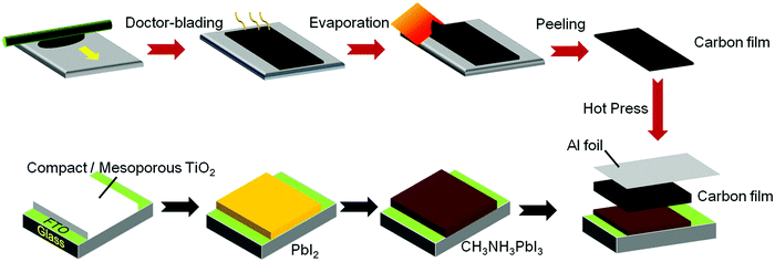 | ||
| Fig. 19 Schematic diagram of the LTCB-cell assembly process using a hot-press approach. Adapted and reproduced with permission from ref. 177. | ||
5.3. Screen-printing
Similarly to the most C-PSCs with high-temperature carbon-based electrodes reported in literature, LTCB-electrodes can also be deposited by screen-printing. This printing method is based on moving a blade across the screen to fill a fine aperture mesh with a paste and then a squeegee applies a pressure on the screen, while moving backwards. In such way, the pressure applied by the squeegee pushes the ink through the aperture area, which touches the substrate only in the locations corresponding to the aperture area, while the rest of the ink is blocked by stencils. Consequently, the resulting print area is fully defined by the screen aperture area, whereas its thickness depends on mesh properties and printing parameters. A big advantage of a screen-printing technique, in comparison, for instance, to blade-coating, is the ability of precise layer patterning (without the use of masks), at an accuracy which is defined by the screen fineness. Notably, it can also be applicable to roll-to-roll manufacturing.5.4. Other deposition methods
The ink-jet printing technique was demonstrated as a deposition method for fabricating a low temperature nanocarbon electrode in HSL-free mesoscopic PSCs. The carbon ink was formulated with the addition of CH3NH3I, which allowed in situ transformation of a PbI2 layer into CH3NH3PbI3 perovskite (Fig. 20a).184 With this strategy, improved characteristics of perovskite/carbon interface were obtained, reaching 11.60% efficiency. Furthermore, the ink-jet technique allowed the production of precisely controlled patterns of carbon electrode.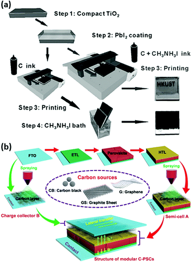 | ||
| Fig. 20 (a) Schematic demonstration of the process flow for fabricating perovskite solar cells with an ink-jet printed carbon electrode (two alternative routes are shown). (b) Overview of the fabrication process of the LTCB-cells with a sprayed carbon electrode. Adapted and reproduced with permissions from ref. 184 and 185. | ||
In the work of Zhang et al., three commercialized carbon sources (graphene, carbon black, graphite sheet) have been tested as back electrodes in an innovative modular PSC design, where the carbon materials were sprayed upon the HTM (Fig. 20b).185 Remarkably, the sheet resistance and thickness were dramatically reduced by covering the cell with an additional carbon-coated FTO glass with applied pressure. Among different carbon sources, graphene provided the best performance for a carbon-based PSC with an impressive PCE of 18.65%. The device performance could maintain 90% of its initial PCE after ageing at 85 °C for 1000 h without encapsulation. Notably, the optimized graphene-based PSCs exhibited excellent structural flexibility with negligible degradation in PCE with multiple re-assembling (detaching the substrate with a half-cell and re-attaching it back) for more than 500 cycles, providing a promising strategy for facile repair and maintenance of the PSC through modular interconnections.
6. Strategies to reach high efficiencies using a low-temperature carbon electrode
As demonstrated earlier, the cells with a low-temperature carbon-based electrode have already shown superior PCEs to the ones produced by a high-temperature method. However, to our knowledge, they still have not surpassed a PCE of 20%. Despite the physical limitations of LTCB-materials for PSCs, we are confident that there are still multiple ways to improve them and bring the power-conversion efficiencies of C-PSCs closer to the ones with metal-electrodes. In Fig. 21 we highlight that the main properties that need to be optimized in order to close this efficiency gap are conductivity, charge selectivity and perovskite/carbon contact.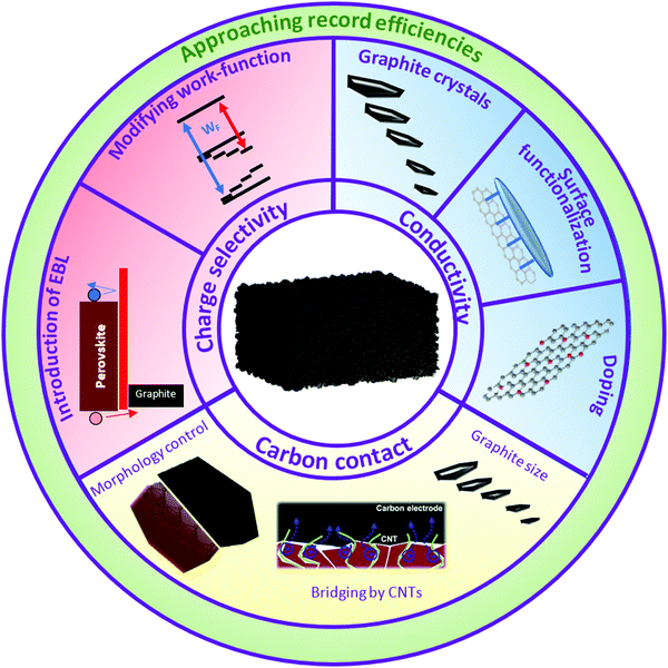 | ||
| Fig. 21 Proposed approaches to improve the PCE of low-temperature carbon-based cells. Partially adapted and reproduced with permissions from ref. 188 and 189. | ||
6.1. Increase of conductivity
By definition, metals are materials where the Fermi level of electrons lies within the conduction band of this material. This leaves electrons free to travel through the lattice. Due to highly periodic lattice in noble metals, the mobility of free charge carriers is generally higher than in semiconductors and most of the carbon-based materials.Graphite particles (which are present in most of the carbon-based electrodes) consist of stacked graphene sheets.190,191 Graphene has a hexagonally close packed crystal structure and is a 2D layer of periodically arranged carbon atoms interconnected by covalent bonds.192 These graphene sheets can be AB stacked upon each other by weak van der Waals forces to form graphite or can be wrapped into a tube shape, which would form a carbon nanotube (CNT). Graphene is formed by sp2 hybridization of carbon with neighboring three carbon atoms, while the fourth valence electron (2pz) is delocalized and forms a π-orbital.191 These delocalized π-electrons have ultra-high mobility along the sheet and are responsible for such low resistivity of graphene, which is even lower than silver. Since graphite consists of stacked graphene sheets it has high conductivity in the direction along the carbon-sheets, but worse conductivity between the sheets, leading to anisotropic electrical nature of graphite.191 Since carbon-based electrodes in PSCs consist not only of multiple graphite flakes, but also carbon black particles, the layer conductivity is severely decreased. Nevertheless, there were several effective strategies suggested to enhance this property by doping, altering graphite size and functionalization of the carbon surface.
 | ||
| Fig. 22 Schematic of the boron-doped graphite preparation process. Reproduced with permissions from ref. 189. | ||
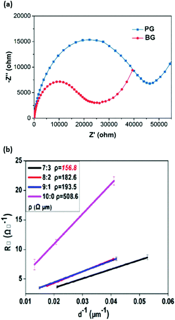 | ||
Fig. 23 (a) Nyquist plots of the PSCs with boron-doped (BG) and boron-free (PG) carbon-based electrodes. (b) Square resistance measurements of LTCB-electrodes with varied graphite to carbon-black ratio (G![[thin space (1/6-em)]](https://www.rsc.org/images/entities/char_2009.gif) : :![[thin space (1/6-em)]](https://www.rsc.org/images/entities/char_2009.gif) CB). Adapted and reproduced with permissions from ref. 189 and 180. CB). Adapted and reproduced with permissions from ref. 189 and 180. | ||
One of the first studies investigating the increase of CNT conductivity by boron doping on the electrical behavior of CNTs was conducted by Liu et al.194 Moreover, Zheng et al. have achieved noticeably higher PCEs through the incorporation of boron doped multi-walled carbon nanotubes (MWCNTs) in their PSC structure as back contact electrodes.195 The authors demonstrated that boron doping MWCNTs through thermal annealing allows an increase in their work function, carrier concentration and conductivity, enhancing their hole extraction and transport properties and therefore the performance of the PSC, with a PCE improvement from around 10.7% with undoped MWCNTs to approximately 14.6% with B-doped MWCNTs with a relatively insignificant hysteresis and an efficiency of over 15.2% with an added aluminum oxide (Al2O3) as an insulating layer.
The impact of vapor assisted trifluoromethanesulfonic acid (TFMS) ex situ doping was investigated by Lee et al. Such doping was performed through exposing self-standing CNT sheets to TFMS vapor.196 The authors found that it effectively improved the conductivity of CNTs and their performance in PSCs, reaching an outstanding PCE of 17.6%, with 72% fill factor. The TFMS-doped CNT-based devices have also shown a better stability compared to undoped devices.
We expect that the methods of CNT doping presented above can also be applied to the carbon-based electrodes, in order to decrease the series resistance losses and enhance the power conversion efficiency of the PV device.
The graphite particle size has been found to play a role in the conductivity of the layer, where lower square resistance can be achieved with larger flakes.199 The size distribution as well as contact area between the graphite flakes directly affect the interparticle resistance and represent a critical parameter to consider during the manufacturing process of the carbon-based paste.180 Notably, the ratio of graphite to carbon-black particles is another factor that requires fine-tuning to reach the highest conductivity of the carbon-based layer. Despite the fact that graphite is more conductive than carbon-black, the latter particles serve as a crucial inter-particle medium for graphite and a significant portion of it is required to obtain highly conductive carbon-based electrodes.180 Based on the studies from Jones et al.200 and Jiang et al.180 the optimal ratio of graphite to carbon-black was found to be (7![[thin space (1/6-em)]](https://www.rsc.org/images/entities/char_2009.gif) :
:![[thin space (1/6-em)]](https://www.rsc.org/images/entities/char_2009.gif) 3) as shown in Fig. 23b; however, reports with various ratios have been shown in the literature,201 which is probably related to the disparity between the used graphite and carbon-black powders.
3) as shown in Fig. 23b; however, reports with various ratios have been shown in the literature,201 which is probably related to the disparity between the used graphite and carbon-black powders.
We suggest that further exploration of doping techniques, careful control of graphite particle size and surface functionalization of the carbon-based layer can result in the development of effective strategies to improve the layer conductivity and enhance the FF of cells with low-temperature carbon-based contact.
6.2. Improve charge selectivity
As mentioned earlier, the issue of poor hole selectivity in HSL-free perovskite solar cells with a carbon-based electrode has to be solved in order to bridge closer to the high-efficiency cells above 20%. Lack of potential barrier for electrons at the perovskite/carbon interface allows electrons to recombine non-radiatively with holes, resulting in a significant drop of Voc. Therefore, an excellent charge extraction and hole conductivity of the low temperature carbon counter electrode is fundamental to improve device PCE. Many attempts have been made to resolve this issue either by the introduction of an HSL into the cell stack (by adding it to the carbon paste or by depositing a planar layer) or by increasing the work function of a carbon-based electrode. In addition, the introduction of an electron-blocking layer on the LTCB-surface can also resolve the issue of electron–hole recombination at the back contact. The main advantage of the low-temperature carbon-based electrode is its compatibility with any given structure and versatility of implementation, which makes it an ideal candidate to reach comparable PCEs with record-breaking cells with metal-based electrodes, while maintaining superior stability.In addition to improving the conductivity, doping (e.g. by boron) was found to alter the work-function of the carbon-based layer (Fig. 24a).189 Chen et al. fabricated a PSC involving boron (B) and phosphorus (P) co-doped carbon electrode through coating the B-atoms onto a hydrothermally P-doped carbon layer. The B/P-doped carbon layer showed an improved work function and electrical conductivity compared to the pristine pure carbon sample.193 By adding a surface modifying layer to an electrode, it is also possible to alter its surface dipole, which has a direct influence on the material work-function.211 Another carbon-layer modification by p-doping was demonstrated by Kim et al., where the authors exposed a complete HSL-free cell to C4F8 plasma treatment as a post-processing step. They found that such fluorine-based treatment was able to form various C-Fx groups, which in turn increase the work-function of the electrode (Fig. 24b).209 Tian et al. have proposed a method to increase the work function of carbon-based electrodes by augmenting the oxygen content in them (Fig. 24c and d).210 The authors attributed the increase in work function to the introduction of sp3 hybridization into the sp2 conjugated hexagonal lattice during formation of graphite, resulting in an increase of interplanar distance along the (002) plane. A similar difference in work-function between pure graphene (4.6 eV) and graphene oxide (4.9 eV) was demonstrated earlier in organic PV cells, making it a promising HTM.212 Since oxygen is more electronegative than carbon, the creation of a surface dipole has been proposed as the underlying reason behind the shift in work-function of graphene oxide. TFMS acid doping of counter electrode CNTs has been proved to improve their conductivity as well as tune their work function, from 4.75 eV to 4.96 eV, subsequently enhancing the energy alignment of the cell and Voc.196
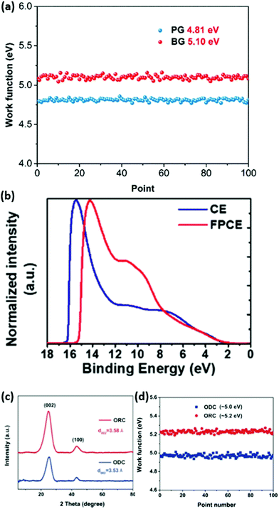 | ||
| Fig. 24 (a) Work function curves of the boron-free (PG) and boron-doped (BG) carbon-based electrodes. (b) UPS spectra of standard (CE) and fluorine-plasma treated (FPCE) carbon electrodes, highlighting the higher secondary electron cut-off region and work-function in the fluorine-plasma doped electrode. (c) XRD-patterns and (d) work-function curves of oxygen-deficient (ODC) and oxygen-rich (ORC) carbon electrodes. Adapted and reprinted with permissions from ref. 189, 209 and 210. | ||
Li et al. have shown that a device with a carbon/graphite/single-walled carbon nanotube (SWCNT) counter electrode mixture (Fig. 25) yielded an improved efficiency of 14.7% compared to devices employing pristine carbon CE.213 This was attributed to the higher work function of 4.7 eV measured for carbon/SWCNT layers as well as to the longer interfacial charge recombination lifetime at the perovskite/SWCNT–carbon electrode interface.
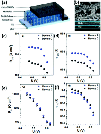 | ||
| Fig. 25 (a) Schematic device architecture with SWCNTs integrated into the carbon-based counter electrode. (b) SEM image of the fabricated device. (c) Charge transfer resistance, (d) charge lifetime at the carbon-based counter electrode (CE), (e) interfacial recombination resistance, and (f) charge lifetime at the interface between perovskite and carbon-based electrode as a function of applied bias. Adapted and reprinted with permission from ref. 213. | ||
Another strategy to modify the work function of carbon electrodes was demonstrated with a p-type material of high hole mobility blended into the carbon formulation. He et al. used copper phtalocyanine (CuPc) addition to change the carbon bulk properties (Fig. 26a).138 The work function measured by ultraviolet photoelectron spectroscopy increased from 4.03 eV for the unmodified carbon to 4.22 eV for the paste blended with 1 wt.% of CuPc (Fig. 26b). Upward shift of the electrode work function resulted in a better hole extraction and overall PCE improvement, from 11.4% to 14.8%. The cells were fabricated in an HSL-free perovskite solar cell architecture (structure: FTO/TiO2/MAPbI3/carbon). Additionally, the authors compared the performance of CuPc-modified carbon devices with the ones where a CuPc interlayer was thermally evaporated between the perovskite and bare carbon layer. The modification of the carbon bulk properties yielded better results than the insertion of CuPc as the HSL.
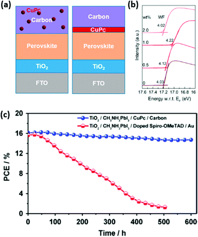 | ||
| Fig. 26 (a) Schematics of integration of a copper phthalocyanine (CuPc) HSL into the cell stack by embedding it into the carbon paste and by introducing it as a planar interlayer. (b) UPS measurements of different contents of CuPc in the carbon-paste displaying ability to tune the work-function of the LTCB-electrode by varying the CuPc thickness. (c) Stability tests of perovskite solar cells using CuPc and LTCB-electrode vs. spiro-OMeTAD and Au-cathode. Adapted and reproduced with permissions from ref. 138 and 142. | ||
Hu et al. observed that incorporating small amounts of CuS into their LTCB-layer leads to improved hole extraction and reduced recombination at the back electrode.214 Similar effects were reported for different metal oxides embedded into the high temperature carbon paste. Tungsten oxide (WOx) nanoparticles were utilized to facilitate a more effective hole collection, which resulted in improved Jsc.215 Jiang et al. conducted extensive research on the metal-oxide modifiers (Co2O3, CuO, MoO3 and NiO) of carbon-based electrodes, which increased the work function and improved the hole selectivity at the perovskite/carbon interface.216 Since these metal oxide additives are applicable for the HTCB-pastes, they can also be embedded into the LTCB-formulations.
Most of the reported perovskite solar cells with a carbon-based back contact electrode are fabricated in a “normal” configuration, which means that holes are collected at the carbon layer. The strategy of work function modification could also be extended to the upward shift (lowering work function). This could provide energetic alignment more favorable for electron extraction, and realization of “inverted” perovskite solar cell configurations.
A study conducted by Zhou et al. demonstrated that polyethylenimine (PEI) surface modified super-aligned cross stacked CNTs employed as counter electrodes for inverted planar PSCs allow for a better energy level alignment throughout the cell, consequently enhancing the photovoltaic performance of the cell.205 These improvements were attributed to the impact of the PEI surface modification on the work function of the CNTs, which leads to reducing electron accumulation and suppressing interfacial charge recombination.
One way to reduce the non-radiative recombination in HSL-free cells is to introduce an electron-blocking layer at the carbon electrode surface. A blocking layer has a slightly different function from a charge-selective layer, although they often possess similar physical properties. The main requirement of a charge-blocking layer is not to extract and conduct charges to the respective electrode, but to only effectively block the charge carriers from reaching the electrode of the opposite charge, which would otherwise result in higher recombination (e.g. hole-blocking c-TiO2 layer). Therefore, a thin, compact, electron-blocking layer would be enough to significantly reduce surface non-radiative recombination enhancing the Voc of the device.
In a recent work by Liu et al., MABr was deposited on top of a MAPbI3 absorber with an excess of PbI2, which predominantly located at the layer surface.217 The excess of PbI2 reacting with MABr can form MAPbI3−xBrx perovskite on top of MAPbI3, resulting in stacking structures. The authors found that due to the upshift of Pb 4f7/2 and I 3d5/2 core levels by 0.31 eV, both the valence band maximum and conduction bands were upshifted in the MAPbI3−xBrx layer (located at the MAPbI3/graphite interface) by 0.23 eV and 0.25 eV, respectively (Fig. 27). This intermediate layer facilitates easier extraction of holes, but more importantly, it forms an energy barrier for excited electrons diffusing towards the carbon-based electrode.
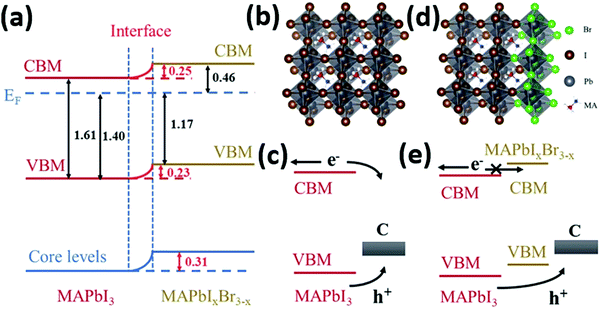 | ||
| Fig. 27 (a) Energy level diagram of the stacked MAPbI3/MAPbIxBr3−x perovskite interface. (b) Crystal structure and (c) charge transfer diagram at the MAPbI3/carbon electrode interface. (d) Crystal structure and (e) charge transfer diagram of the stacked MAPbI3. Adapted and reprinted with permission from ref. 217. | ||
6.3. Improving contact to the perovskite
One of the strong suits of evaporated metal-electrodes is homogeneous and dense layer deposition, which facilitates efficient contact to the underlying charge selective layer. However, often the perovskite/carbon interface suffers from a low number of interfacial contact sites and poor adhesion, which seriously limits hole extraction and transport in the PV device.31 Moreover, we believe that the introduction of barriers under the carbon-based electrode, that have been mentioned earlier in Section 2.1.3 will facilitate an even longer operational stability of the C-PSCs, in comparison to that of devices with metallic contacts.Liu et al. found that the interfacial charge transfer between the perovskite and LTCB-layer is highly influenced by the size of graphite particles.179 Besides conductivity, the graphite size also has an influence on the perovskite/carbon contact area, which can be increased by decreasing the particle size (Fig. 28).178 Thus, finding a careful balance between a high conductivity and an efficient hole-extraction would be optimal for reaching high PCEs with carbon-based electrodes. A poor contact between the perovskite and carbon-based electrode can also lead to larger anion migration towards the interface, which will increase hysteresis.141 Addition of NiO-modifier also promoted a more intimate contact at this interface and enhanced the charge transfer rate.216
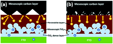 | ||
| Fig. 28 Scheme of charge transfer in HTM-free CH3NH3PbI3/TiO2 heterojunction solar cells with a carbon electrode, consisting of (a) large and (b) small graphite flakes. Adapted and reprinted with permission from ref. 178. | ||
It is clear, that solvents in the LTCB-pastes play a critical role in determining the properties of the final electrode and should be compatible with the perovskite and layers underneath the LTCB-layer to form a smooth, intimate interface.218 In contrast, there were reports that solvents present in the LTCB-paste, which are not fully compatible with the perovskite layer,218 can lead to significant damage of the perovskite morphology and worsen the interface characteristics. In some cases, LTCB-paste can contain polar solvents (e.g. ethyl carbitol acetate or alcohols) that can dissolve the layers underneath, including perovskite since the paste is directly applied on top of the cell layers. Hence, we advocate for LTCB-pastes with “harmless” solvents preserving dense and uniform morphology, resulting in lower interfacial resistance and higher stability.171
Similarly, Chen et al. in the work mentioned above, improved the electronic contact at the perovskite/carbon interface by growing smoother perovskite films of higher surface quality. The obtained 14.38% PCE was a record value for a HSL-free carbon-based PSC at that time.
Notably, carbon nanotubes manifest impressive electrical conductivity properties making them an excellent candidate for improving the hole conductivity of the carbon electrode and decreasing interfacial recombination resistance at the carbon/perovskite interface. In addition, many studies on C-PSCs have aimed at improving the electrical conductivity as well as enhancing the charge selectivity at the perovskite/carbon interface through the incorporation of different additives, the most promising among which are carbon nanotubes. The incorporation of CNTs in perovskite solar cells has demonstrated a noticeable improvement in device performance.219
For example, Wang et al. have opted for a “bridging method”, where they incorporated CNTs into both: the perovskite and carbon electrode (Fig. 29), for the purpose of forming a better interface quality via CNT-bridges between these layers.188 The cells showed a efficiency of over 15.7%, with a FF of around 70%.
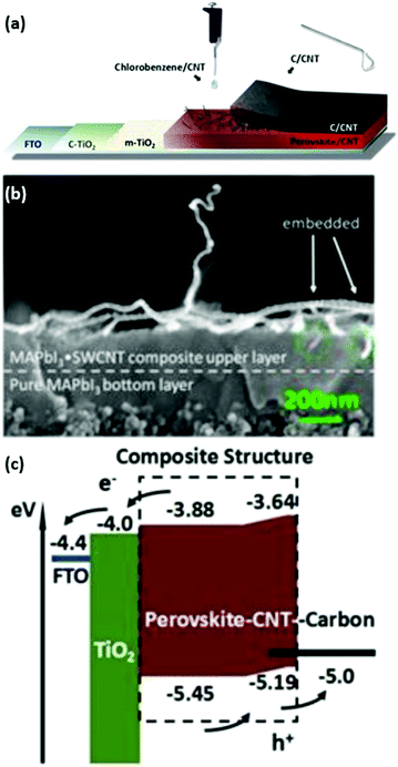 | ||
| Fig. 29 (a) LTCB-device architecture with CNTs incorporated into the perovskite and electrode. (b) Cross-sectional SEM image and (c) energy band diagram of such device. Adapted and reprinted with permission from ref. 188. | ||
An alternative strategy is to incorporate CNTs between the perovskite and carbon electrode layers. Ryu et al. introduced a MWCNT chlorobenzene dispersion into the complete LTCB-cells by a dripping method.220 The MWCNTs, penetrating both the perovskite absorber and carbon electrode, created a pathway that allowed for more optimal carrier harvesting and transport properties, achieving a PCE of 13.57%.
Yet another approach for improved hole selectivity and reduced recombination could be obtained with the perovskite surface modification at the perovskite/carbon interface. Hou et al. applied guanidinium chloride into MAPbI3 perovskite precursor solution.221 The additive passivated trap states in the perovskite layer and reduced recombination rate at the perovskite/carbon interface (mesoscopic architecture, TiO2/ZrO2/carbon, infiltrated with perovskite solution). This led to Voc enhancement, from 0.88 V to 1.02 V. Rong et al. used ammonium chloride (NH4Cl) additive in the precursor solution, which also improved the optoelectronic quality of MAPbI3 films.222 Impressive efficiency of 15.6% was reported for the same mesoscopic, triple-layer scaffold architecture (TiO2/ZrO2/carbon).
Liu et al. applied cesium acetate (CsAc) treatment after the carbon deposition.223 They suggested that the acetate salt could penetrate to the buried perovskite surface, modifying its composition, which grants a higher hole selectivity. The CsAc treatment improved the average PCE of HSL-free devices, from 12.6% to 15.3%, with a Voc value reaching 1.1 V. Another defect post-healing method was shown with dip-coating pre-fabricated carbon-based mesoscopic PSCs in trioctylphosphine oxide (TOPO) solution.224 TOPO ligands act as a Lewis base, selectively adsorbing onto halide-deficient defects sites at the perovskite surface, reducing non-radiative recombination at the interface with a carbon electrode (Fig. 30). PCE improved after the treatment from 11% to 12.8%, primarily due to the Voc increase. In another example, Liu et al. applied polydimethylsiloxane (PDMS) encapsulant on carbon-based, HSL-free mesoscopic MAPbI3/TiO2 heterojunction solar cells.225 It was demonstrated that PDMS, during its solidification, fills the gaps in the mesoporous carbon film, which significantly improves the perovskite/carbon interface characteristics. The authors demonstrated that the charge extraction efficacy was improved and the recombination rate got reduced, which resulted in a 54% enhancement of photovoltaic performance, reaching 10.8% PCE.
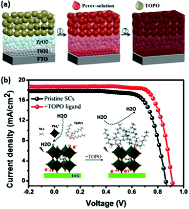 | ||
| Fig. 30 (a) Schematic illustration of a mesoscopic perovskite solar cell fabrication process with a TOPO passivation step; (b) JV curves of a TOPO-passivated device and a reference cell, combined with a schematic drawing of the TOPO interaction with perovskite defects. Adapted and reprinted with permission from ref. 224. | ||
Similarly, different strategies for improving electronic contact and charge selectivity at the interface with the carbon electrode were also demonstrated for the inverted perovskite solar cell architecture (p–i–n configuration). Luo et al. reported devices utilizing a back contact electrode based on transfer-printed carbon nanotubes.226 In order to improve the efficacy of electron extraction from the perovskite layer, the authors applied SnO2-coated cross-stacked carbon nanotubes (SnO2@CSCNT). The SnO2 coating improved the PCE from 10.7% to 14.3%, with significantly reduced hysteresis. Furthermore, flexible PSCs applying a SnO2-modified CNT electrode were demonstrated, reaching 10.5% efficiency.
Recently, Babu et al. demonstrated a Cr buffer layer inserted between the electron transport layer and carbon electrode as a way to obtain Ohmic contact at that interface and efficient charge collection in p–i–n devices.163 They reported 15.18% PCE for a flexible perovskite solar cell (Fig. 31) with a large active area of 1 cm2. Furthermore, a Cr interlayer was also applied in n–i–p configuration, inserted between the hole transport layer and carbon electrode. It resulted in an improvement in fill factor, assigned to improved electronic contact, yielding 12.06% PCE (flexible PSC, 1 cm2 active area).
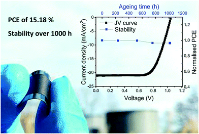 | ||
| Fig. 31 J–V curve and performance evolution during aging test of a flexible inverted PSC with a carbon back contact electrode. Adapted and reprinted with permission from ref. 163. | ||
7. Conclusions
7.1. Summary
Most of the state-of-the-art perovskite solar cells use metal electrodes as a back contact, attempting to bridge cell efficiencies closer to the radiative limits. However, in this review we point out that poor stability of these metallic layers, limited up-scalability potential, high costs and negative environmental impact hinder further development of perovskite PV in the direction of commercialization. Therefore, carbon-based electrodes have been proposed to alleviate these issues and to fulfill the potential of perovskite to become the next generation PV technology.Comparing between high-temperature and low-temperature cured carbon-based layers, the latter ones come along with multiple processing advantages: (1) easier integration of hole-selective layers, owing to the electrode low curing temperature, which is compatible with perovskites and HSLs, (2) possibility to implement advanced crystallization and passivation techniques (in comparison to poorly controlled crystallization after the solution infiltration in C-PSCs with high-temperature cured electrodes), (3) applicability to flexible substrates and roll-to-toll manufacturing and (4) shorter processing time. Based on the multiple reports showing PCEs above 17% (with 17.8% certified value), we postulate that low-temperature carbon electrodes can be used to produce high-efficiency PSCs, while simultaneously being a more chemically stable, up-scalable, cost-efficient and sustainable alternative to conventional metal contacts.
We summarize different paste formulations present in the literature, displaying the effect of various additives, solvents, binders and carbon powder compositions (e.g. carbon-black to graphite ratios) on the final film properties. Literature on carbon-based electrodes suggests that they can be deposited by blade-coating, press-transfer, screen-printing methods and even ink-jet printing or spray coating all of which are up-scalable techniques and can be implemented to fabricate large area modules.
Furthermore, we propose effective strategies that have been reported for low-temperature carbon-based electrodes, to improve the layer conductivity, charge selectivity and contact between carbon and the layer underneath: (1) a higher conductivity can be reached by modification of graphite crystals and its portion in the paste, surface functionalization and foreign atom doping. (2) Enhancing charge selectivity is suggested to be improved by modification of the work-function and integration of electron-blocking layers at the perovskite/carbon interface. (3) Finally, a better contact at the carbon surface can be obtained by producing smooth pin-hole free films, introducing carbon-nanotubes to facilitate better interfacial charge transfer and tuning the graphite size.
7.2. Perspective
In order to overcome the voltage loss of still 200 mV compared to the highest-efficiency cells, two conditions have to be fulfilled: non-radiative surface recombination at the back-contact has to be reduced and the valence (for n–i–p cells) or conduction (for p–i–n cells) band of the back-contact have to match the energy levels of the perovskite absorber, which can be achieved by tuning the carbon-based electrode or by adding a selective layer in between. In this review, different strategies have been proposed: to introduce an HSL as an electron-blocking and hole-conducting layer between the perovskite and carbon-based electrode or to modify the work-function of the carbon electrode itself.To increase the photo-current and fill factor of the C-PSCs, the efficient extraction of holes from the perovskite to graphite is required, highlighting the necessity to find a method to reach this goal. The low-temperature cured carbon-based layers display clear advantages of higher flexibility in implementing the strategies mentioned above, originating from the capability of the LTCB-layer to be applied before or after the perovskite deposition. In particular, this allows for new options for functionalizing the interface at the perovskite/carbon contact. It is not surprising that in the last few years PSCs with low-temperature cured electrodes have already reached higher efficiencies than the ones with high-temperature treated contacts.
Overall, we emphasize that the vast knowledge acquired by the perovskite community on methods to fabricate high-efficiency solar cells so far can be readily transferred to low-temperature carbon-based perovskite solar cells, which represents strong potential to bring perovskite technology closer to the PV market.
Author contributions
D. B., L. W., S. M., S. Z. and A. H. proposed the idea of summarizing the recent progress in low-temperature carbon-based electrodes in PSCs and identifying their advantages. B. Y. together with D. B. and A. H. described the stability disadvantages of conventional PSCs as well as reported stability measurements of carbon-based PSCs. S. M. together with L. W. analyzed the environmental concerns of conventional PSCs, while J. L. together with L. W. conducted a literature research on the cost analysis of PSCs. D. B., J. L. and B. Y. described the differences between the low- and high-temperature carbon based devices, as well as advantages of crystallization control, and ability to introduce a wider range of HSLs. K. W., V. B. and D. B. further elaborated how these low-temperature carbon-based electrodes can be applied on flexible substrates and allow for faster manufacturing process. B. X. and H. P. together with D. B. summarized the low-temperature carbon paste formulations. The carbon layer deposition methods were described by K. W., V. B., D. B., B. X. and B. Y. Among the proposed strategies to improve low-temperature carbon-based electrodes, D. B., S. Z. and L. W. analyzed the conductivity improvement methods. K. W., V. B., D. B., L. W., S. Z. and A. H. contributed to the description of charge selectivity improvement strategies. K. W., V. B., S. Z. and D. B. identified effective methods to improve the perovskite/carbon interface. A. H., A. H. and D. B. summarized the findings and provided the perspective. All authors contributed to the study with valuable discussions and reviewed the manuscript. This work is a result of the well-coordinated collaboration between European Research institutes, Universities and industrial partners.Conflicts of interest
K. W. is an employee of Saule Tech, A. H. and H. P. are the co-founders of Dyenamo AB, Bo Xu is an employee of Dyenamo AB.Acknowledgements
This work was partially funded within the projects PROPER financed from the German Ministry of Education and Research under funding number 01DR19007 and UNIQUE supported under the umbrella of the SOLAR-ERA.NET_cofund by ANR, PtJ, MIUR, MINECO-AEI and SWEA, within the EU's HORIZON 2020 Research and Innovation Program (cofund ERA-NET Action No. 691664). D. B. and L. W. acknowledge the scholarship support of the German Federal Environmental Foundation (DBU). S. Z. acknowledges the scholarship support of the German Academic Exchange Service (DAAD). K. W. acknowledges the financial support from the Foundation of Polish Science (First TEAM/2017-3/30), V. B. acknowledges funding from the European Union's Horizon 2020 MSCA Innovative Training Network under grant agreement No. 764787 (MAESTRO). B. Y. and A. H. acknowledge the funding from the European Union's Horizon 2020 research and innovation program ESPRESSO under the agreement No.: 764047.References
- A. Kojima, K. Teshima, Y. Shirai and T. Miyasaka, Organometal halide perovskites as visible-light sensitizers for photovoltaic cells, J. Am. Chem. Soc., 2009, 131, 6050–6051 CrossRef CAS.
- G. E. Eperon, S. D. Stranks, C. Menelaou, M. B. Johnston, L. M. Herz and H. J. Snaith, Formamidinium lead trihalide: a broadly tunable perovskite for efficient planar heterojunction solar cells, Energy Environ. Sci., 2014, 7, 982 RSC.
- M. R. Filip, G. E. Eperon, H. J. Snaith and F. Giustino, Steric engineering of metal-halide perovskites with tunable optical band gaps, Nat. Commun., 2014, 5, 5757 CrossRef CAS.
- R. J. Sutton, G. E. Eperon, L. Miranda, E. S. Parrott, B. A. Kamino, J. B. Patel, M. T. Hörantner, M. B. Johnston, A. A. Haghighirad and D. T. Moore, et al., Bandgap-Tunable Cesium Lead Halide Perovskites with High Thermal Stability for Efficient Solar Cells, Adv. Energy Mater., 2016, 6, 1502458 CrossRef.
- J. Sun, J. Wu, X. Tong, F. Lin, Y. Wang and Z. M. Wang, Organic/Inorganic Metal Halide Perovskite Optoelectronic Devices beyond Solar Cells, Adv. Sci., 2018, 5, 1700780 CrossRef.
- L. Mao, Y. Wu, C. C. Stoumpos, M. R. Wasielewski and M. G. Kanatzidis, White-Light Emission and Structural Distortion in New Corrugated Two-Dimensional Lead Bromide Perovskites, J. Am. Chem. Soc., 2017, 139, 5210–5215 CrossRef CAS.
- L. Meng, E.-P. Yao, Z. Hong, H. Chen, P. Sun, Z. Yang, G. Li and Y. Yang, Pure Formamidinium-Based Perovskite Light-Emitting Diodes with High Efficiency and Low Driving Voltage, Adv. Mater., 2017, 29, 1603826 CrossRef.
- A. Sadhanala, A. Kumar, S. Pathak, A. Rao, U. Steiner, N. C. Greenham, H. J. Snaith and R. H. Friend, Electroluminescence from Organometallic Lead Halide Perovskite-Conjugated Polymer Diodes, Adv. Electron. Mater., 2015, 1, 1500008 CrossRef.
- T. Gupta, D. Ghoshal, A. Yoshimura, S. Basu, P. K. Chow, A. S. Lakhnot, J. Pandey, J. M. Warrender, H. Efstathiadis and A. Soni, et al., An Environmentally Stable and Lead-Free Chalcogenide Perovskite, Adv. Funct. Mater., 2020, 30, 2001387 CrossRef CAS.
- L. Dou, Y. M. Yang, J. You, Z. Hong, W.-H. Chang, G. Li and Y. Yang, Solution-processed hybrid perovskite photodetectors with high detectivity, Nat. Commun., 2014, 5, 5404 CrossRef CAS.
- X. Hu, X. Zhang, L. Liang, J. Bao, S. Li, W. Yang and Y. Xie, High-Performance Flexible Broadband Photodetector Based on Organolead Halide Perovskite, Adv. Funct. Mater., 2014, 24, 7373–7380 CrossRef CAS.
- Y. Guo, C. Liu, H. Tanaka and E. Nakamura, Air-Stable and Solution-Processable Perovskite Photodetectors for Solar-Blind UV and Visible Light, J. Phys. Chem. Lett., 2015, 6, 535–539 CrossRef CAS.
- F. Bella, P. Renzi, C. Cavallo and C. Gerbaldi, Caesium for Perovskite Solar Cells: An Overview, Chemistry, 2018, 24, 12183–12205 CrossRef CAS.
- L. Gu, M. M. Tavakoli, D. Zhang, Q. Zhang, A. Waleed, Y. Xiao, K.-H. Tsui, Y. Lin, L. Liao and J. Wang, et al., 3D Arrays of 1024-Pixel Image Sensors based on Lead Halide Perovskite Nanowires, Adv. Mater., 2016, 28, 9713–9721 CrossRef CAS.
- W. Deng, X. Zhang, L. Huang, X. Xu, L. Wang, J. Wang, Q. Shang, S.-T. Lee and J. Jie, Aligned Single-Crystalline Perovskite Microwire Arrays for High-Performance Flexible Image Sensors with Long-Term Stability, Adv. Mater., 2016, 28, 2201–2208 CrossRef CAS.
- Y. Wang, Y. Zhu, J. Huang, J. Cai, J. Zhu, X. Yang, J. Shen and C. Li, Perovskite quantum dots encapsulated in electrospun fiber membranes as multifunctional supersensitive sensors for biomolecules, metal ions and pH, Nanoscale Horiz., 2017, 2, 225–232 RSC.
- T. N. Huan, D. A. Dalla Corte, S. Lamaison, D. Karapinar, L. Lutz, N. Menguy, M. Foldyna, S.-H. Turren-Cruz, A. Hagfeldt and F. Bella, et al., Low-cost high-efficiency system for solar-driven conversion of CO2 to hydrocarbons, Proc. Natl. Acad. Sci. U. S. A., 2019, 116, 9735–9740 CrossRef CAS.
- M. F. Aygüler, M. D. Weber, B. M. D. Puscher, D. D. Medina, P. Docampo and R. D. Costa, Light-Emitting Electrochemical Cells Based on Hybrid Lead Halide Perovskite Nanoparticles, J. Phys. Chem. C, 2015, 119, 12047–12054 CrossRef.
- A. Aguadero, D. Pérez-Coll, J. A. Alonso, S. J. Skinner and J. Kilner, A New Family of Mo-Doped SrCoO 3−δ Perovskites for Application in Reversible Solid State Electrochemical Cells, Chem. Mater., 2012, 24, 2655–2663 CrossRef CAS.
- Y. Rong, Y. Hu, A. Mei, H. Tan, M. I. Saidaminov, S. I. Seok, M. D. McGehee, E. H. Sargent and H. Han, Challenges for commercializing perovskite solar cells, Science, 2018, 361(6408), eaat8235 CrossRef.
- Y. Rong, L. Liu, A. Mei, X. Li and H. Han, Beyond Efficiency: the Challenge of Stability in Mesoscopic Perovskite Solar Cells, Adv. Energy Mater., 2015, 5, 1501066 CrossRef.
- J.-P. Correa-Baena, M. Saliba, T. Buonassisi, M. Grätzel, A. Abate, W. Tress and A. Hagfeldt, Promises and challenges of perovskite solar cells, Science, 2017, 358, 739–744 CrossRef CAS.
- D. Wang, M. Wright, N. K. Elumalai and A. Uddin, Stability of perovskite solar cells, Sol. Energy Mater. Sol. Cells, 2016, 147, 255–275 CrossRef CAS.
- Q. Wali, F. J. Iftikhar, M. E. Khan, A. Ullah, Y. Iqbal and R. Jose, Advances in stability of perovskite solar cells, Org. Electron., 2020, 78, 105590 CrossRef CAS.
- J. S. Manser, M. I. Saidaminov, J. A. Christians, O. M. Bakr and P. V. Kamat, Making and Breaking of Lead Halide Perovskites, Acc. Chem. Res., 2016, 49, 330–338 CrossRef CAS.
- D. Meggiolaro, E. Mosconi and F. de. Angelis, Formation of Surface Defects Dominates Ion Migration in Lead-Halide Perovskites, ACS Energy Lett., 2019, 4, 779–785 CrossRef CAS.
- J. M. Ball and A. Petrozza, Defects in perovskite-halides and their effects in solar cells, Nat. Energy, 2016, 1, 16149 CrossRef CAS.
- B. Conings, J. Drijkoningen, N. Gauquelin, A. Babayigit, J. D'Haen, L. D'Olieslaeger, A. Ethirajan, J. Verbeeck, J. Manca and E. Mosconi, et al., Intrinsic Thermal Instability of Methylammonium Lead Trihalide Perovskite, Adv. Energy Mater., 2015, 5, 1500477 CrossRef.
- Z. Ku, Y. Rong, M. Xu, T. Liu and H. Han, Full printable processed mesoscopic CH3NH3PbI3/TiO2 heterojunction solar cells with carbon counter electrode, Sci. Rep., 2013, 3, 3132 CrossRef.
- Q. Wang, N. Phung, D. Di Girolamo, P. Vivo and A. Abate, Enhancement in lifespan of halide perovskite solar cells, Energy Environ. Sci., 2019, 12, 865–886 RSC.
- F. Meng, A. Liu, L. Gao, J. Cao, Y. Yan, N. Wang, M. Fan, G. Wei and T. Ma, Current progress in interfacial engineering of carbon-based perovskite solar cells, J. Mater. Chem. A, 2019, 7, 8690–8699 RSC.
- A. Mei, X. Li, L. Liu, Z. Ku, T. Liu, Y. Rong, M. Xu, M. Hu, J. Chen and Y. Yang, et al., A hole-conductor-free, fully printable mesoscopic perovskite solar cell with high stability, Science, 2014, 345, 295–298 CrossRef CAS.
- L. Fagiolari and F. Bella, Carbon-based materials for stable, cheaper and large-scale processable perovskite solar cells, Energy Environ. Sci., 2019, 12, 3437–3472 RSC.
- M. Hadadian, J.-H. Smått and J.-P. Correa-Baena, The role of carbon-based materials in enhancing the stability of perovskite solar cells, Energy Environ. Sci., 2020, 13, 1377–1407 RSC.
- M. V. Khenkin, K. M. Anoop, E. A. Katz and I. Visoly-Fisher, Bias-dependent degradation of various solar cells: lessons for stability of perovskite photovoltaics, Energy Environ. Sci., 2019, 12, 550–558 RSC.
- L. Meng, J. You and Y. Yang, Addressing the stability issue of perovskite solar cells for commercial applications, Nat. Commun., 2018, 9, 5265 CrossRef CAS.
- G. Niu, X. Guo and L. Wang, Review of recent progress in chemical stability of perovskite solar cells, J. Mater. Chem. A, 2015, 3, 8970–8980 RSC.
- N. H. Tiep, Z. Ku and H. J. Fan, Recent Advances in Improving the Stability of Perovskite Solar Cells, Adv. Energy Mater., 2016, 6, 1501420 CrossRef.
- Q. Fu, X. Tang, B. Huang, T. Hu, L. Tan, L. Chen and Y. Chen, Recent Progress on the Long-Term Stability of Perovskite Solar Cells, Adv. Sci., 2018, 5, 1700387 CrossRef.
- K. Domanski, E. A. Alharbi, A. Hagfeldt, M. Grätzel and W. Tress, Systematic investigation of the impact of operation conditions on the degradation behaviour of perovskite solar cells, Nat. Energy, 2018, 3, 61–67 CrossRef CAS.
- L. K. Ono, Y. Qi and S. Liu, Progress toward Stable Lead Halide Perovskite Solar Cells, Joule, 2018, 2, 1961–1990 CrossRef CAS.
- M. V. Khenkin, E. A. Katz, A. Abate, G. Bardizza, J. J. Berry, C. Brabec, F. Brunetti, V. Bulović, Q. Burlingame and A. Di Carlo, et al., Consensus statement for stability assessment and reporting for perovskite photovoltaics based on ISOS procedures, Nat. Energy, 2020, 5, 35–49 CrossRef.
- B. Philippe, B.-W. Park, R. Lindblad, J. Oscarsson, S. Ahmadi, E. M. J. Johansson and H. Rensmo, Chemical and Electronic Structure Characterization of Lead Halide Perovskites and Stability Behavior under Different Exposures—A Photoelectron Spectroscopy Investigation, Chem. Mater., 2015, 27, 1720–1731 CrossRef CAS.
- J. M. Frost, K. T. Butler, F. Brivio, C. H. Hendon, M. van Schilfgaarde and A. Walsh, Atomistic origins of high-performance in hybrid halide perovskite solar cells, Nano Lett., 2014, 14, 2584–2590 CrossRef CAS.
- F. Li and M. Liu, Recent efficient strategies for improving the moisture stability of perovskite solar cells, J. Mater. Chem. A, 2017, 5, 15447–15459 RSC.
- J. Huang, S. Tan, P. D. Lund and H. Zhou, Impact of H 2 O on organic–inorganic hybrid perovskite solar cells, Energy Environ. Sci., 2017, 10, 2284–2311 RSC.
- R. Wang, M. Mujahid, Y. Duan, Z.-K. Wang, J. Xue and Y. Yang, A Review of Perovskites Solar Cell Stability, Adv. Funct. Mater., 2019, 29, 1808843 CrossRef CAS.
- J. A. Christians, P. A. Miranda Herrera and P. V. Kamat, Transformation of the excited state and photovoltaic efficiency of CH3NH3PbI3 perovskite upon controlled exposure to humidified air, J. Am. Chem. Soc., 2015, 137, 1530–1538 CrossRef CAS.
- J. Yang, B. D. Siempelkamp, D. Liu and T. L. Kelly, Investigation of CH3NH3PbI3 degradation rates and mechanisms in controlled humidity environments using in situ techniques, ACS Nano, 2015, 9, 1955–1963 CrossRef CAS.
- A. M. A. Leguy, Y. Hu, M. Campoy-Quiles, M. I. Alonso, O. J. Weber, P. Azarhoosh, M. van Schilfgaarde, M. T. Weller, T. Bein and J. Nelson, et al., Reversible Hydration of CH 3 NH 3 PbI 3 in Films, Single Crystals, and Solar Cells, Chem. Mater., 2015, 27, 3397–3407 CrossRef CAS.
- C. C. Stoumpos, C. D. Malliakas and M. G. Kanatzidis, Semiconducting tin and lead iodide perovskites with organic cations: phase transitions, high mobilities, and near-infrared photoluminescent properties, Inorg. Chem., 2013, 52, 9019–9038 CrossRef CAS.
- J.-W. Lee, D.-H. Kim, H.-S. Kim, S.-W. Seo, S. M. Cho and N.-G. Park, Formamidinium and Cesium Hybridization for Photo- and Moisture-Stable Perovskite Solar Cell, Adv. Energy Mater., 2015, 5, 1501310 CrossRef.
- D. L. Busipalli, K.-Y. Lin, S. Nachimuthu and J.-C. Jiang, Enhanced moisture stability of cesium lead iodide perovskite solar cells – a first-principles molecular dynamics study, Phys. Chem. Chem. Phys., 2020, 22, 5693–5701 RSC.
- W. Ahmad, J. Khan, G. Niu and J. Tang, Inorganic CsPbI 3 Perovskite-Based Solar Cells: A Choice for a Tandem Device, Sol. RRL, 2017, 1, 1700048 CrossRef.
- Y. Liu, S. Akin, L. Pan, R. Uchida, N. Arora, J. V. Milić, A. Hinderhofer, F. Schreiber, A. R. Uhl and S. M. Zakeeruddin, et al., Ultrahydrophobic 3D/2D fluoroarene bilayer-based water-resistant perovskite solar cells with efficiencies exceeding 22, Sci. Adv., 2019, 5, eaaw2543 CrossRef CAS.
- S. Zhang, Z. Liu, W. Zhang, Z. Jiang, W. Chen, R. Chen, Y. Huang, Z. Yang, Y. Zhang and L. Han, et al., Barrier Designs in Perovskite Solar Cells for Long-Term Stability, Adv. Energy Mater., 2020, 2001610 CrossRef CAS.
- H. Zhu, Y. Liu, F. T. Eickemeyer, L. Pan, D. Ren, M. A. Ruiz-Preciado, B. Carlsen, B. Yang, X. Dong and Z. Wang, et al., Tailored Amphiphilic Molecular Mitigators for Stable Perovskite Solar Cells with 23.5% Efficiency, Adv. Mater., 2020, 32, e1907757 CrossRef.
- R. Wang, J. Xue, K.-L. Wang, Z.-K. Wang, Y. Luo, D. Fenning, G. Xu, S. Nuryyeva, T. Huang and Y. Zhao, et al., Constructive molecular configurations for surface-defect passivation of perovskite photovoltaics, Science, 2019, 366, 1509–1513 CrossRef CAS.
- C. Fei, M. Zhou, J. Ogle, D.-M. Smilgies, L. Whittaker-Brooks and H. Wang, Self-assembled propylammonium cations at grain boundaries and the film surface to improve the efficiency and stability of perovskite solar cells, J. Mater. Chem. A, 2019, 7, 23739–23746 RSC.
- Y. Cho, A. M. Soufiani, J. S. Yun, J. Kim, D. S. Lee, J. Seidel, X. Deng, M. A. Green, S. Huang and A. W. Y. Ho-Baillie, Mixed 3D-2D Passivation Treatment for Mixed-Cation Lead Mixed-Halide Perovskite Solar Cells for Higher Efficiency and Better Stability, Adv. Energy Mater., 2018, 8, 1703392 CrossRef.
- G.-W. Kim, G. Kang, K. Choi, H. Choi and T. Park, Solution Processable Inorganic-Organic Double-Layered Hole Transport Layer for Highly Stable Planar Perovskite Solar Cells, Adv. Energy Mater., 2018, 8, 1801386 CrossRef.
- S. Yang, S. Chen, E. Mosconi, Y. Fang, X. Xiao, C. Wang, Y. Zhou, Z. Yu, J. Zhao and Y. Gao, et al., Stabilizing halide perovskite surfaces for solar cell operation with wide-bandgap lead oxysalts, Science, 2019, 365, 473–478 CrossRef CAS.
- J. H. Kim, P.-W. Liang, S. T. Williams, N. Cho, C.-C. Chueh, M. S. Glaz, D. S. Ginger and A. K.-Y. Jen, High-performance and environmentally stable planar heterojunction perovskite solar cells based on a solution-processed copper-doped nickel oxide hole-transporting layer, Adv. Mater., 2015, 27, 695–701 CrossRef CAS.
- J. You, L. Meng, T.-B. Song, T.-F. Guo, Y. M. Yang, W.-H. Chang, Z. Hong, H. Chen, H. Zhou and Q. Chen, et al., Improved air stability of perovskite solar cells via solution-processed metal oxide transport layers, Nat. Nanotechnol., 2016, 11, 75–81 CrossRef CAS.
- K. Liu, Y. Yao, J. Wang, L. Zhu, M. Sun, B. Ren, L. Xie, Y. Luo, Q. Meng and X. Zhan, Spiro[fluorene-9,9′-xanthene]-based hole transporting materials for efficient perovskite solar cells with enhanced stability, Mater. Chem. Front., 2017, 1, 100–110 RSC.
- G.-W. Kim, G. Kang, M. Malekshahi Byranvand, G.-Y. Lee and T. Park, Gradated Mixed Hole Transport Layer in a Perovskite Solar Cell: Improving Moisture Stability and Efficiency, ACS Appl. Mater. Interfaces, 2017, 9, 27720–27726 CrossRef CAS.
- Y. Yue, N. Salim, Y. Wu, X. Yang, A. Islam, W. Chen, J. Liu, E. Bi, F. Xie and M. Cai, et al., Enhanced Stability of Perovskite Solar Cells through Corrosion-Free Pyridine Derivatives in Hole-Transporting Materials, Adv. Mater., 2016, 28, 10738–10743 CrossRef CAS.
- S. M. Jain, Z. Qiu, L. Häggman, M. Mirmohades, M. B. Johansson, T. Edvinsson and G. Boschloo, Frustrated Lewis pair-mediated recrystallization of CH 3 NH 3 PbI 3 for improved optoelectronic quality and high voltage planar perovskite solar cells, Energy Environ. Sci., 2016, 9, 3770–3782 RSC.
- Z. Hawash, L. K. Ono, S. R. Raga, M. V. Lee and Y. Qi, Air-Exposure Induced Dopant Redistribution and Energy Level Shifts in Spin-Coated Spiro-MeOTAD Films, Chem. Mater., 2015, 27, 562–569 CrossRef CAS.
- T. Xu, L. Chen, Z. Guo and T. Ma, Strategic improvement of the long-term stability of perovskite materials and perovskite solar cells, Phys. Chem. Chem. Phys., 2016, 18, 27026–27050 RSC.
- J.-Y. Seo, H.-S. Kim, S. Akin, M. Stojanovic, E. Simon, M. Fleischer, A. Hagfeldt, S. M. Zakeeruddin and M. Grätzel, Novel p-dopant toward highly efficient and stable perovskite solar cells, Energy Environ. Sci., 2018, 11, 2985–2992 RSC.
- Y. Saygili, H.-S. Kim, B. Yang, J. Suo, A. B. Muñoz-Garcia, M. Pavone and A. Hagfeldt, Revealing the Mechanism of Doping of spiro -MeOTAD via Zn Complexation in the Absence of Oxygen and Light, ACS Energy Lett., 2020, 5, 1271–1277 CrossRef CAS.
- K. Rakstys, C. Igci and M. K. Nazeeruddin, Efficiency vs. stability: dopant-free hole transporting materials towards stabilized perovskite solar cells, Chem. Sci., 2019, 10, 6748–6769 RSC.
- D. Molina, M. A. Ruiz-Preciado, B. Carlsen, F. T. Eickemeyer, B. Yang, N. Flores-Díaz, M. J. Álvaro-Martins, K. Nonomura, A. Hagfeldt and Á. Sastre-Santos, Zinc Phthalocyanine Conjugated Dimers as Efficient Dopant-Free Hole Transporting Materials in Perovskite Solar Cells, ChemPhotoChem, 2020, 4, 307–314 CrossRef CAS.
- L. Zhang, C. Liu, X. Wang, Y. Tian, A. K. Y. Jen and B. Xu, Side-Chain Engineering on Dopant-Free Hole-Transporting Polymers toward Highly Efficient Perovskite Solar Cells (20.19%), Adv. Funct. Mater., 2019, 29, 1904856 CrossRef.
- R. Chen, T. Bu, J. Li, W. Li, P. Zhou, X. Liu, Z. Ku, J. Zhong, Y. Peng and F. Huang, et al., Efficient and Stable Inverted Planar Perovskite Solar Cells Using a Triphenylamine Hole-Transporting Material, ChemSusChem, 2018, 11, 1467–1473 CrossRef CAS.
- Y. Li, K. R. Scheel, R. G. Clevenger, W. Shou, H. Pan, K. V. Kilway and Z. Peng, Highly Efficient and Stable Perovskite Solar Cells Using a Dopant-Free Inexpensive Small Molecule as the Hole-Transporting Material, Adv. Energy Mater., 2018, 8, 1801248 CrossRef.
- R. Azmi, S. Y. Nam, S. Sinaga, Z. A. Akbar, C.-L. Lee, S. C. Yoon, I. H. Jung and S.-Y. Jang, High-performance dopant-free conjugated small molecule-based hole-transport materials for perovskite solar cells, Nano Energy, 2018, 44, 191–198 CrossRef CAS.
- X. Jiang, D. Wang, Z. Yu, W. Ma, H.-B. Li, X. Yang, F. Liu, A. Hagfeldt and L. Sun, Molecular Engineering of Copper Phthalocyanines: A Strategy in Developing Dopant-Free Hole-Transporting Materials for Efficient and Ambient-Stable Perovskite Solar Cells, Adv. Energy Mater., 2019, 9, 1803287 CrossRef.
- K. Norrman, M. V. Madsen, S. A. Gevorgyan and F. C. Krebs, Degradation patterns in water and oxygen of an inverted polymer solar cell, J. Am. Chem. Soc., 2010, 132, 16883–16892 CrossRef CAS.
- Z. Song; A. Abate; S. C. Watthage; G. K. Liyanage; A. B. Phillips; U. Steiner; M. Graetzel and M. J. Heben, In situ observation of moisture-induced degradation of perovskite solar cells using laser-beam induced current. In 2016 IEEE 43rd Photovoltaic Specialists Conference (PVSC), 5–10 June 2016, Conference, I. P. S., Ed.; IEEE: [Piscataway, NJ], 2016, pp. 1202–1206.
- S. Kazim, F. J. Ramos, P. Gao, M. K. Nazeeruddin, M. Grätzel and S. Ahmad, A dopant free linear acene derivative as a hole transport material for perovskite pigmented solar cells, Energy Environ. Sci., 2015, 8, 1816–1823 RSC.
- L. Etgar, P. Gao, Z. Xue, Q. Peng, A. K. Chandiran, B. Liu, M. K. Nazeeruddin and M. Grätzel, Mesoscopic CH3NH3PbI3/TiO2 heterojunction solar cells, J. Am. Chem. Soc., 2012, 134, 17396–17399 CrossRef CAS.
- X. Yin, Y. Guo, H. Xie, W. Que and L. B. Kong, Nickel Oxide as Efficient Hole Transport Materials for Perovskite Solar Cells, Sol. RRL, 2019, 3, 1900001 CrossRef.
- Z. Liu, A. Zhu, F. Cai, L. Tao, Y. Zhou, Z. Zhao, Q. Chen, Y.-B. Cheng and H. Zhou, Nickel oxide nanoparticles for efficient hole transport in p–i–n and n–i–p perovskite solar cells, J. Mater. Chem. A, 2017, 5, 6597–6605 RSC.
- J. Cao, H. Yu, S. Zhou, M. Qin, T.-K. Lau, X. Lu, N. Zhao and C.-P. Wong, Low-temperature solution-processed NiOx films for air-stable perovskite solar cells, J. Mater. Chem. A, 2017, 5, 11071–11077 RSC.
- H. Zhang, H. Wang, W. Chen and A. K.-Y. Jen, CuGaO2: A Promising Inorganic Hole-Transporting Material for Highly Efficient and Stable Perovskite Solar Cells, Adv. Mater., 2017, 29, 1604984 CrossRef.
- S. Seo, S. Jeong, C. Bae, N.-G. Park and H. Shin, Perovskite Solar Cells with Inorganic Electron- and Hole-Transport Layers Exhibiting Long-Term (≈500 h) Stability at 85 °C under Continuous 1 Sun Illumination in Ambient Air, Adv. Mater., 2018, e1801010 CrossRef.
- K. Domanski, J.-P. Correa-Baena, N. Mine, M. K. Nazeeruddin, A. Abate, M. Saliba, W. Tress, A. Hagfeldt and M. Grätzel, Not All That Glitters Is Gold: Metal-Migration-Induced Degradation in Perovskite Solar Cells, ACS Nano, 2016, 10, 6306–6314 CrossRef CAS.
- C. Besleaga, L. E. Abramiuc, V. Stancu, A. G. Tomulescu, M. Sima, L. Trinca, N. Plugaru, L. Pintilie, G. A. Nemnes and M. Iliescu, et al., Iodine Migration and Degradation of Perovskite Solar Cells Enhanced by Metallic Electrodes, J. Phys. Chem. Lett., 2016, 7, 5168–5175 CrossRef CAS.
- A. Guerrero, J. You, C. Aranda, Y. S. Kang, G. Garcia-Belmonte, H. Zhou, J. Bisquert and Y. Yang, Interfacial Degradation of Planar Lead Halide Perovskite Solar Cells, ACS Nano, 2016, 10, 218–224 CrossRef CAS.
- K. E. A. Hooper, H. K. H. Lee, M. J. Newman, S. Meroni, J. Baker, T. M. Watson and W. C. Tsoi, Probing the degradation and homogeneity of embedded perovskite semiconducting layers in photovoltaic devices by Raman spectroscopy, Phys. Chem. Chem. Phys., 2017, 19, 5246–5253 RSC.
- S. Svanström, T. J. Jacobsson, G. Boschloo, E. M. J. Johansson, H. Rensmo and U. B. Cappel, Degradation Mechanism of Silver Metal Deposited on Lead Halide Perovskites, ACS Appl. Mater. Interfaces, 2020, 12, 7212–7221 CrossRef.
- L. Wang, G.-R. Li, Q. Zhao and X.-P. Gao, Non-precious transition metals as counter electrode of perovskite solar cells, Energy Storage Mater., 2017, 7, 40–47 CrossRef.
- C. C. Boyd, R. Cheacharoen, K. A. Bush, R. Prasanna, T. Leijtens and M. D. McGehee, Barrier Design to Prevent Metal-Induced Degradation and Improve Thermal Stability in Perovskite Solar Cells, ACS Energy Lett., 2018, 3, 1772–1778 CrossRef CAS.
- J. Li, Q. Dong, N. Li and L. Wang, Direct Evidence of Ion Diffusion for the Silver-Electrode-Induced Thermal Degradation of Inverted Perovskite Solar Cells, Adv. Energy Mater., 2017, 7, 1602922 CrossRef.
- J. Zhao, X. Zheng, Y. Deng, T. Li, Y. Shao, A. Gruverman, J. Shield and J. Huang, Is Cu a stable electrode material in hybrid perovskite solar cells for a 30-year lifetime?, Energy Environ. Sci., 2016, 9, 3650–3656 RSC.
- N. Arora, M. I. Dar, A. Hinderhofer, N. Pellet, F. Schreiber, S. M. Zakeeruddin and M. Grätzel, Perovskite solar cells with CuSCN hole extraction layers yield stabilized efficiencies greater than 20, Science, 2017, 358, 768–771 CrossRef CAS.
- S. Wu, R. Chen, S. Zhang, B. H. Babu, Y. Yue, H. Zhu, Z. Yang, C. Chen, W. Chen and Y. Huang, et al., A chemically inert bismuth interlayer enhances long-term stability of inverted perovskite solar cells, Nat. Commun., 2019, 10, 1161 CrossRef.
- J.-W. Xiao, C. Shi, C. Zhou, D. Zhang, Y. Li and Q. Chen, Contact Engineering: Electrode Materials for Highly Efficient and Stable Perovskite Solar Cells, Sol. RRL, 2017, 1, 1700082 CrossRef.
- H. Xie and M. Lira-Cantu, Multi-component engineering to enable long-term operational stability of perovskite solar cells, J. Phys.: Energy, 2020, 2, 024008 CAS.
- W. Xiang and W. Tress, Review on Recent Progress of All-Inorganic Metal Halide Perovskites and Solar Cells, Adv. Mater., 2019, 31, e1902851 CrossRef.
- R. Cheacharoen, C. C. Boyd, G. F. Burkhard, T. Leijtens, J. A. Raiford, K. A. Bush, S. F. Bent and M. D. McGehee, Encapsulating perovskite solar cells to withstand damp heat and thermal cycling, Sustainable Energy Fuels, 2018, 2, 2398–2406 RSC.
- L. Shi, M. P. Bucknall, T. L. Young, M. Zhang, L. Hu, J. Bing, D. S. Lee, J. Kim, T. Wu and N. Takamure, et al., Gas chromatography-mass spectrometry analyses of encapsulated stable perovskite solar cells, Science, 2020, 368(6497), eaba2412 CrossRef CAS.
- Z. Liu, L. Qiu, L. K. Ono, S. He, Z. Hu, M. Jiang, G. Tong, Z. Wu, Y. Jiang and D.-Y. Son, et al., A holistic approach to interface stabilization for efficient perovskite solar modules with over 2000-hour operational stability, Nat. Energy, 2020, 5, 596–604 CrossRef CAS.
- J. Chen, Y. Xiong, Y. Rong, A. Mei, Y. Sheng, P. Jiang, Y. Hu, X. Li and H. Han, Solvent effect on the hole-conductor-free fully printable perovskite solar cells, Nano Energy, 2016, 27, 130–137 CrossRef CAS.
- H. Zhou, Y. Shi, Q. Dong, H. Zhang, Y. Xing, K. Wang, Y. Du and T. Ma, Hole-Conductor-Free, Metal-Electrode-Free TiO2/CH3NH3PbI3 Heterojunction Solar Cells Based on a Low-Temperature Carbon Electrode, J. Phys. Chem. Lett., 2014, 5, 3241–3246 CrossRef CAS.
- Z. Yu, B. Chen, P. Liu, C. Wang, C. Bu, N. Cheng, S. Bai, Y. Yan and X. Zhao, Stable Organic-Inorganic Perovskite Solar Cells without Hole-Conductor Layer Achieved via Cell Structure Design and Contact Engineering, Adv. Funct. Mater., 2016, 26, 4866–4873 CrossRef CAS.
- X. Li, M. Tschumi, H. Han, S. S. Babkair, R. A. Alzubaydi, A. A. Ansari, S. S. Habib, M. K. Nazeeruddin and S. M. Zakeeruddin, Grätzel, M. Outdoor Performance and Stability under Elevated Temperatures and Long-Term Light Soaking of Triple-Layer Mesoporous Perovskite Photovoltaics, Energy Technol., 2015, 3, 551–555 CrossRef CAS.
- A. K. Baranwal, S. Kanaya, T. A. N. Peiris, G. Mizuta, T. Nishina, H. Kanda, T. Miyasaka, H. Segawa and S. Ito, 100 °C Thermal Stability of Printable Perovskite Solar Cells Using Porous Carbon Counter Electrodes, ChemSusChem, 2016, 9, 2604–2608 CrossRef CAS.
- S. Gholipour, J.-P. Correa-Baena, K. Domanski, T. Matsui, L. Steier, F. Giordano, F. Tajabadi, W. Tress, M. Saliba and A. Abate, et al., Highly Efficient and Stable Perovskite Solar Cells based on a Low-Cost Carbon Cloth, Adv. Energy Mater., 2016, 6, 1601116 CrossRef.
- G. Grancini, C. Roldán-Carmona, I. Zimmermann, E. Mosconi, X. Lee, D. Martineau, S. Narbey, F. Oswald, F. Angelis and M. de; Graetzel, et al., One-Year stable perovskite solar cells by 2D/3D interface engineering, Nat. Commun., 2017, 8, 15684 CrossRef CAS.
- H. Ye, Z. Liu, X. Liu, B. Sun, X. Tan, Y. Tu, T. Shi, Z. Tang and G. Liao, 17.78% efficient low-temperature carbon-based planar perovskite solar cells using Zn-doped SnO2 electron transport layer, Appl. Surf. Sci., 2019, 478, 417–425 CrossRef CAS.
- H. Zhang, J. Xiao, J. Shi, H. Su, Y. Luo, D. Li, H. Wu, Y.-B. Cheng and Q. Meng, Self-Adhesive Macroporous Carbon Electrodes for Efficient and Stable Perovskite Solar Cells, Adv. Funct. Mater., 2018, 28, 1802985 CrossRef.
- S. Emami, J. Martins, D. Ivanou and A. Mendes, Advanced hermetic encapsulation of perovskite solar cells: the route to commercialization, J. Mater. Chem. A, 2020, 8, 2654–2662 RSC.
- Z. Wu, Z. Liu, Z. Hu, Z. Hawash, L. Qiu, Y. Jiang, L. K. Ono and Y. Qi, Highly Efficient and Stable Perovskite Solar Cells via Modification of Energy Levels at the Perovskite/Carbon Electrode Interface, Adv. Mater., 2019, 31, e1804284 CrossRef.
- A. Priyadarshi, L. J. Haur, P. Murray, D. Fu, S. Kulkarni, G. Xing, T. C. Sum, N. Mathews and S. G. Mhaisalkar, A large area (70 cm2) monolithic perovskite solar module with a high efficiency and stability, Energy Environ. Sci., 2016, 9, 3687–3692 RSC.
- Y. Hu, S. Si, A. Mei, Y. Rong, H. Liu, X. Li and H. Han, Stable Large-Area (10 × 10 cm2) Printable Mesoscopic Perovskite Module Exceeding 10% Efficiency, Sol. RRL, 2017, 1, 1600019 CrossRef.
- N. L. Chang, A. W. Yi Ho-Baillie, P. A. Basore, T. L. Young, R. Evans and R. J. Egan, A manufacturing cost estimation method with uncertainty analysis and its application to perovskite on glass photovoltaic modules, Prog. Photovoltaics, 2017, 25, 390–405 Search PubMed.
- N. L. Chang, A. W. Y. Ho-Baillie, D. Vak, M. Gao, M. A. Green and R. J. Egan, Manufacturing cost and market potential analysis of demonstrated roll-to-roll perovskite photovoltaic cell processes, Sol. Energy Mater. Sol. Cells, 2018, 174, 314–324 CrossRef CAS.
- Z. Song, C. L. McElvany, A. B. Phillips, I. Celik, P. W. Krantz, S. C. Watthage, G. K. Liyanage, D. Apul and M. J. Heben, A technoeconomic analysis of perovskite solar module manufacturing with low-cost materials and techniques, Energy Environ. Sci., 2017, 10, 1297–1305 RSC.
- Z. Li, T. R. Klein, D. H. Kim, M. Yang, J. J. Berry, M. F. A. M. van Hest and K. Zhu, Scalable fabrication of perovskite solar cells, Nat. Rev. Mater., 2018, 3, 18017 CrossRef CAS.
- M. Xu, W. Ji, Y. Sheng, Y. Wu, H. Cheng, J. Meng, Z. Yan, J. Xu, A. Mei and Y. Hu, et al., Efficient triple-mesoscopic perovskite solar mini-modules fabricated with slot-die coating, Nano Energy, 2020, 74, 104842 CrossRef CAS.
- L. Cai, L. Liang, J. Wu, B. Ding, L. Gao and B. Fan, Large area perovskite solar cell module, J. Semicond., 2017, 38, 14006 CrossRef.
- L. Wagner, S. Mastroianni and A. Hinsch, Reverse Manufacturing Enables Perovskite Photovoltaics to Reach the Carbon Footprint Limit of a Glass Substrate, Joule, 2020, 4, 882–901 CrossRef CAS.
- J. Gong, S. B. Darling and F. You, Perovskite photovoltaics: life-cycle assessment of energy and environmental impacts, Energy Environ. Sci., 2015, 8, 1953–1968 RSC.
- T. Ibn-Mohammed, S. C. L. Koh, I. M. Reaney, A. Acquaye, G. Schileo, K. B. Mustapha and R. Greenough, Perovskite solar cells: An integrated hybrid lifecycle assessment and review in comparison with other photovoltaic technologies, Renewable Sustainable Energy Rev., 2017, 80, 1321–1344 CrossRef CAS.
- J.-A. Alberola-Borràs, J. A. Baker, F. Rossi, R. de; Vidal, D. Beynon, K. E. A. Hooper, T. M. Watson and I. Mora-Seró, Perovskite Photovoltaic Modules: Life Cycle Assessment of Pre-industrial Production Process, iScience, 2018, 9, 542–551 CrossRef.
- M. A. Reuter, A. van Schaik, J. Gutzmer, N. Bartie and A. Abadías-Llamas, Challenges of the Circular Economy: A Material, Metallurgical, and Product Design Perspective, Annu. Rev. Mater. Res., 2019, 49, 253–274 CrossRef CAS.
- L. Ciacci, E. M. Harper, N. T. Nassar, B. K. Reck and T. E. Graedel, Metal Dissipation and Inefficient Recycling Intensify Climate Forcing, Environ. Sci. Technol., 2016, 50, 11394–11402 CrossRef CAS.
- AIP Conference Proceedings, AIP Publishing LLC, 2014.
- S. S. Mali, H. Kim, J. V. Patil and C. K. Hong, Bio-inspired Carbon Hole Transporting Layer Derived from Aloe Vera Plant for Cost-Effective Fully Printable Mesoscopic Carbon Perovskite Solar Cells, ACS Appl. Mater. Interfaces, 2018, 10, 31280–31290 CrossRef CAS.
- Z. Liu and H. He, Counter Electrode Materials for Organic-Inorganic Perovskite Solar Cells, in Nanostructured Materials for Next-Generation Energy Storage and Conversion: Photovoltaic and Solar Energy, ed. T. A. Atesin, S. Bashir and J. L. Liu, Springer, Berlin, Heidelberg, 2020, pp. 165–225 Search PubMed.
- S. Sun, T. Buonassisi and J.-P. Correa-Baena, State-of-the-Art Electron-Selective Contacts in Perovskite Solar Cells, Adv. Mater. Interfaces, 2018, 5, 1800408 CrossRef.
- G. Mathiazhagan, L. Wagner, S. Bogati, K. Y. Ünal, D. Bogachuk, T. Kroyer, S. Mastroianni and A. Hinsch, Double-Mesoscopic Hole-Transport-Material-Free Perovskite Solar Cells: Overcoming Charge-Transport Limitation by Sputtered Ultrathin Al2O3 Isolating Layer, ACS Appl. Nano Mater., 2020, 3, 2463–2471 CrossRef CAS.
- X. Xu, Z. Liu, Z. Zuo, M. Zhang, Z. Zhao, Y. Shen, H. Zhou, Q. Chen, Y. Yang and M. Wang, Hole selective NiO contact for efficient perovskite solar cells with carbon electrode, Nano Lett., 2015, 15, 2402–2408 CrossRef CAS.
- S. Liu, W. Huang, P. Liao, N. Pootrakulchote, H. Li, J. Lu, J. Li, F. Huang, X. Shai and X. Zhao, et al., 17% efficient printable mesoscopic PIN metal oxide framework perovskite solar cells using cesium-containing triple cation perovskite, J. Mater. Chem. A, 2017, 5, 22952–22958 RSC.
- S. He, L. Qiu, D.-Y. Son, Z. Liu, E. J. Juarez-Perez, L. K. Ono, C. Stecker and Y. Qi, Carbon-Based Electrode Engineering Boosts the Efficiency of All Low-Temperature-Processed Perovskite Solar Cells, ACS Energy Lett., 2019, 4, 2032–2039 CrossRef CAS.
- J. Ren, J. Qu, J. Chen, Z. Li, Y. Cui, H. Wang, Z. Yu and Y. Hao, Fluorinated dopant-free hole-transporting material for efficient and stable perovskite solar cells with carbon cathode, J. Power Sources, 2018, 401, 29–36 CrossRef CAS.
- F. Zhang, X. Yang, M. Cheng, J. Li, W. Wang, H. Wang and L. Sun, Engineering of hole-selective contact for low temperature-processed carbon counter electrode-based perovskite solar cells, J. Mater. Chem. A, 2015, 3, 24272–24280 RSC.
- S. Wang, P. Jiang, W. Shen, A. Mei, S. Xiong, X. Jiang, Y. Rong, Y. Tang, Y. Hu and H. Han, A low-temperature carbon electrode with good perovskite compatibility and high flexibility in carbon based perovskite solar cells, Chem. Commun., 2019, 55, 2765–2768 RSC.
- F. Zhang, X. Yang, M. Cheng, W. Wang and L. Sun, Boosting the efficiency and the stability of low cost perovskite solar cells by using CuPc nanorods as hole transport material and carbon as counter electrode, Nano Energy, 2016, 20, 108–116 CrossRef CAS.
- S. Mashhoun, Y. Hou, H. Chen, F. Tajabadi, N. Taghavinia, H.-J. Egelhaaf and C. J. Brabec, Resolving a Critical Instability in Perovskite Solar Cells by Designing a Scalable and Printable Carbon Based Electrode-Interface Architecture, Adv. Energy Mater., 2018, 8, 1802085 CrossRef.
- X. Zheng, H. Chen, Z. Wei, Y. Yang, H. Lin and S. Yang, High-performance, stable and low-cost mesoscopic perovskite (CH3NH3PbI3) solar cells based on poly(3-hexylthiophene)-modified carbon nanotube cathodes, Front. Optoelectron., 2016, 9, 71–80 CrossRef.
- A. T. Kleinschmidt, S. E. Root and D. J. Lipomi, Poly(3-hexylthiophene) (P3HT): fruit fly or outlier in organic solar cell research?, J. Mater. Chem. A, 2017, 5, 11396–11400 RSC.
- Q.-Q. Chu, B. Ding, J. Peng, H. Shen, X. Li, Y. Liu, C.-X. Li, C.-J. Li, G.-J. Yang and T. P. White, et al., Highly stable carbon-based perovskite solar cell with a record efficiency of over 18% via hole transport engineering, J. Mater. Sci. Technol., 2019, 35, 987–993 CrossRef.
- K. Cao, Z. Zuo, J. Cui, Y. Shen, T. Moehl, S. M. Zakeeruddin, M. Grätzel and M. Wang, Efficient screen printed perovskite solar cells based on mesoscopic TiO2/Al2O3/NiO/carbon architecture, Nano Energy, 2015, 17, 171–179 CrossRef CAS.
- F. Behrouznejad, C.-M. Tsai, S. Narra, E. W.-G. Diau and N. Taghavinia, Interfacial Investigation on Printable Carbon-Based Mesoscopic Perovskite Solar Cells with NiOx/C Back Electrode, ACS Appl. Mater. Interfaces, 2017, 9, 25204–25215 CrossRef CAS.
- T. A. N. Peiris, A. K. Baranwal, H. Kanda, S. Fukumoto, S. Kanaya, L. Cojocaru, T. Bessho, T. Miyasaka, H. Segawa and S. Ito, Enhancement of the hole conducting effect of NiO by a N2 blow drying method in printable perovskite solar cells with low-temperature carbon as the counter electrode, Nanoscale, 2017, 9, 5475–5482 RSC.
- W. A. Dunlap-Shohl, Y. Zhou, N. P. Padture and D. B. Mitzi, Synthetic Approaches for Halide Perovskite Thin Films, Chem. Rev., 2019, 119, 3193–3295 CrossRef CAS.
- H. Chen, Z. Wei, H. He, X. Zheng, K. S. Wong and S. Yang, Solvent Engineering Boosts the Efficiency of Paintable Carbon-Based Perovskite Solar Cells to Beyond 14%, Adv. Energy Mater., 2016, 6, 1502087 CrossRef.
- H. Chen, X. Zheng, Q. Li, Y. Yang, S. Xiao, C. Hu, Y. Bai, T. Zhang, K. S. Wong and S. Yang, An amorphous precursor route to the conformable oriented crystallization of CH3NH3PbBr3 in mesoporous scaffolds: toward efficient and thermally stable carbon-based perovskite solar cells, J. Mater. Chem. A, 2016, 4, 12897–12912 RSC.
- S. Bai, N. Cheng, Z. Yu, P. Liu, C. Wang and X.-Z. Zhao, Cubic: Column composite structure (NH2CH
![[double bond, length as m-dash]](https://www.rsc.org/images/entities/char_e001.gif) NH2)x(CH3NH3)1−xPbI3 for efficient hole-transport material-free and insulation layer free perovskite solar cells with high stability, Electrochim. Acta, 2016, 190, 775–779 CrossRef CAS.
NH2)x(CH3NH3)1−xPbI3 for efficient hole-transport material-free and insulation layer free perovskite solar cells with high stability, Electrochim. Acta, 2016, 190, 775–779 CrossRef CAS. - X. Chang, W. Li, H. Chen, L. Zhu, H. Liu, H. Geng, S. Xiang, J. Liu, X. Zheng and Y. Yang, et al., Colloidal Precursor-Induced Growth of Ultra-Even CH3NH3PbI3 for High-Performance Paintable Carbon-Based Perovskite Solar Cells, ACS Appl. Mater. Interfaces, 2016, 8, 30184–30192 CrossRef CAS.
- C. Zhang, Y. Luo, X. Chen, Y. Chen, Z. Sun and S. Huang, Effective Improvement of the Photovoltaic Performance of Carbon-Based Perovskite Solar Cells by Additional Solvents, Nano-Micro Lett., 2016, 8, 347–357 CrossRef.
- X. Zhou, Y. Wang, C. Li and T. Wu, Doping amino-functionalized ionic liquid in perovskite crystal for enhancing performances of hole-conductor free solar cells with carbon electrode, Chem. Eng. J., 2019, 372, 46–52 CrossRef CAS.
- X. Liu, Z. Liu, B. Sun, X. Tan, H. Ye, Y. Tu, T. Shi, Z. Tang and G. Liao, 17.46% efficient and highly stable carbon-based planar perovskite solar cells employing Ni-doped rutile TiO2 as electron transport layer, Nano Energy, 2018, 50, 201–211 CrossRef CAS.
- J. Liang, C. Wang, Y. Wang, Z. Xu, Z. Lu, Y. Ma, H. Zhu, Y. Hu, C. Xiao and X. Yi, et al., All-Inorganic Perovskite Solar Cells, J. Am. Chem. Soc., 2016, 138, 15829–15832 CrossRef CAS.
- J. Liang, P. Zhao, C. Wang, Y. Wang, Y. Hu, G. Zhu, L. Ma, J. Liu and Z. Jin, CsPb0.9Sn0.1IBr2 Based All-Inorganic Perovskite Solar Cells with Exceptional Efficiency and Stability, J. Am. Chem. Soc., 2017, 139, 14009–14012 CrossRef CAS.
- J. Liang, Z. Liu, L. Qiu, Z. Hawash, L. Meng, Z. Wu, Y. Jiang, L. K. Ono and Y. Qi, Enhancing Optical, Electronic, Crystalline, and Morphological Properties of Cesium Lead Halide by Mn Substitution for High-Stability All-Inorganic Perovskite Solar Cells with Carbon Electrodes, Adv. Energy Mater., 2018, 8, 1800504 CrossRef.
- E. Calabrò, F. Matteocci, B. Paci, L. Cinà, L. Vesce, J. Barichello, A. Generosi, A. Reale and A. Di Carlo, Easy Strategy to Enhance Thermal Stability of Planar PSCs by Perovskite Defect Passivation and Low-Temperature Carbon-Based Electrode, ACS Appl. Mater. Interfaces, 2020, 12(29), 32536–32547 CrossRef.
- A. Clough, D. Peng, Z. Yang and O. K. C. Tsui, Glass Transition Temperature of Polymer Films That Slip, Macromolecules, 2011, 44, 1649–1653 CrossRef CAS.
- V. Babu, R. Fuentes Pineda, T. Ahmad, A. O. Alvarez, L. A. Castriotta, A. Di Carlo, F. Fabregat-Santiago and K. Wojciechowski, Improved Stability of Inverted and Flexible Perovskite Solar Cells with Carbon Electrode, ACS Appl. Energy Mater., 2020, 3, 5126–5134 CrossRef CAS.
- J. Troughton, D. Bryant, K. Wojciechowski, M. J. Carnie, H. Snaith, D. A. Worsley and T. M. Watson, Highly efficient, flexible, indium-free perovskite solar cells employing metallic substrates, J. Mater. Chem. A, 2015, 3, 9141–9145 RSC.
- B. Zimmermann, M. Glatthaar, M. Niggemann, M. K. Riede, A. Hinsch and A. Gombert, ITO-free wrap through organic solar cells—A module concept for cost-efficient reel-to-reel production, Sol. Energy Mater. Sol. Cells, 2007, 91, 374–378 CrossRef CAS.
- J. Baker, K. Hooper, S. Meroni, A. Pockett, J. McGettrick, Z. Wei, R. Escalante, G. Oskam, M. Carnie and T. Watson, High throughput fabrication of mesoporous carbon perovskite solar cells, J. Mater. Chem. A, 2017, 5, 18643–18650 RSC.
- B. Dou, J. B. Whitaker, K. Bruening, D. T. Moore, L. M. Wheeler, J. Ryter, N. J. Breslin, J. J. Berry, S. M. Garner and F. S. Barnes, et al., Roll-to-Roll Printing of Perovskite Solar Cells, ACS Energy Lett., 2018, 3, 2558–2565 CrossRef CAS.
- D. Bogachuk, L. Wagner, S. Mastroianni, M. Daub, H. Hillebrecht and A. Hinsch, The Nature of Methylamine-MAPbI3 Complex: Fundamentals of Gas-Induced Perovskite Liquefaction and Crystallization, J. Mater. Chem. A, 2020, 8, 9788–9796 RSC.
- Y. Galagan, F. Di Giacomo, H. Gorter, G. Kirchner, I. Vries, R. de; Andriessen and P. Groen, Roll-to-Roll Slot Die Coated Perovskite for Efficient Flexible Solar Cells, Adv. Energy Mater., 2018, 8, 1801935 CrossRef.
- L. Wagner, S. Chacko, G. Mathiazhagan, S. Mastroianni and A. Hinsch, High Photovoltage of 1 V on a Steady-State Certified Hole Transport Layer-Free Perovskite Solar Cell by a Molten-Salt Approach, ACS Energy Lett., 2018, 3, 1122–1127 CrossRef CAS.
- Q.-Q. Chu, B. Ding, Q. Qiu, Y. Liu, C.-X. Li, C.-J. Li, G.-J. Yang and B. Fang, Cost effective perovskite solar cells with a high efficiency and open-circuit voltage based on a perovskite-friendly carbon electrode, J. Mater. Chem. A, 2018, 6, 8271–8279 RSC.
- S. Bai, P. Da, C. Li, Z. Wang, Z. Yuan, F. Fu, M. Kawecki, X. Liu, N. Sakai and J. T.-W. Wang, et al., Planar perovskite solar cells with long-term stability using ionic liquid additives, Nature, 2019, 571, 245–250 CrossRef CAS.
- Y. Guan, M. Xu, W. Zhang, D. Li, X. Hou, L. Hong, Q. Wang, Z. Zhang, A. Mei and M. Chen, et al., In situ transfer of CH3NH3PbI3 single crystals in mesoporous scaffolds for efficient perovskite solar cells, Chem. Sci., 2020, 11, 474–481 RSC.
- H. Su, J. Xiao, Q. Li, C. Peng, X. Zhang, C. Mao, Q. Yao, Y. Lu, Z. Ku and J. Zhong, et al., Carbon film electrode based square-centimeter scale planar perovskite solar cells exceeding 17% efficiency, Mater. Sci. Semicond. Process., 2020, 107, 104809 CrossRef CAS.
- Z. Wei, K. Yan, H. Chen, Y. Yi, T. Zhang, X. Long, J. Li, L. Zhang, J. Wang and S. Yang, Cost-efficient clamping solar cells using candle soot for hole extraction from ambipolar perovskites, Energy Environ. Sci., 2014, 7, 3326–3333 RSC.
- R. Dileep, G. Kesavan, V. Reddy, M. K. Rajbhar, S. Shanmugasundaram, E. Ramasamy and G. Veerappan, Room-temperature curable carbon cathode for hole-conductor free perovskite solar cells, Sol. Energy, 2019, 187, 261–268 CrossRef CAS.
- H. Wei, J. Xiao, Y. Yang, S. Lv, J. Shi, X. Xu, J. Dong, Y. Luo, D. Li and Q. Meng, Free-standing flexible carbon electrode for highly efficient hole-conductor-free perovskite solar cells, Carbon, 2015, 93, 861–868 CrossRef CAS.
- Y. Yang, J. Xiao, H. Wei, L. Zhu, D. Li, Y. Luo, H. Wu and Q. Meng, An all-carbon counter electrode for highly efficient hole-conductor-free organo-metal perovskite solar cells, RSC Adv., 2014, 4, 52825–52830 RSC.
- Z. Liu, T. Shi, Z. Tang, B. Sun and G. Liao, Using a low-temperature carbon electrode for preparing hole-conductor-free perovskite heterojunction solar cells under high relative humidity, Nanoscale, 2016, 8, 7017–7023 RSC.
- P. Jiang, T. W. Jones, N. W. Duffy, K. F. Anderson, R. Bennett, M. Grigore, P. Marvig, Y. Xiong, T. Liu and Y. Sheng, et al., Fully printable perovskite solar cells with highly-conductive, low-temperature, perovskite-compatible carbon electrode, Carbon, 2018, 129, 830–836 CrossRef CAS.
- Q.-Q. Chu, B. Ding, Y. Li, L. Gao, Q. Qiu, C.-X. Li, C.-J. Li, G.-J. Yang and B. Fang, Fast Drying Boosted Performance Improvement of Low-Temperature Paintable Carbon-Based Perovskite Solar Cell, ACS Sustainable Chem. Eng., 2017, 5, 9758–9765 CrossRef CAS.
- Y. Yang, M. T. Hoang, D. Yao, N. D. Pham, V. T. Tiong, X. Wang, W. Sun and H. Wang, High performance carbon-based planar perovskite solar cells by hot-pressing approach, Sol. Energy Mater. Sol. Cells, 2020, 210, 110517 CrossRef CAS.
- F. Meng, L. Gao, Y. Yan, J. Cao, N. Wang, T. Wang and T. Ma, Ultra-low-cost coal-based carbon electrodes with seamless interfacial contact for effective sandwich-structured perovskite solar cells, Carbon, 2019, 145, 290–296 CrossRef CAS.
- Z. Wei, H. Chen, K. Yan and S. Yang, Inkjet printing and instant chemical transformation of a CH3NH3PbI3/nanocarbon electrode and interface for planar perovskite solar cells, Angew. Chem., Int. Ed., 2014, 53, 13239–13243 CrossRef CAS.
- C. Zhang, S. Wang, H. Zhang, Y. Feng, W. Tian, Y. Yan, J. Bian, Y. Wang, S. Jin and S. M. Zakeeruddin, et al., Efficient stable graphene-based perovskite solar cells with high flexibility in device assembling via modular architecture design, Energy Environ. Sci., 2019, 12, 3585–3594 RSC.
- Z. Liu, B. Sun, X. Liu, J. Han, H. Ye, Y. Tu, C. Chen, T. Shi, Z. Tang and G. Liao, 15% efficient carbon based planar-heterojunction perovskite solar cells using a TiO 2/SnO 2 bilayer as the electron transport layer, J. Mater. Chem. A, 2018, 6, 7409–7419 RSC.
- F. Deng, X. Li, X. Lv, J. Zhou, Y. Chen, X. Sun, Y.-Z. Zheng, X. Tao and J.-F. Chen, Low-Temperature Processing All-Inorganic Carbon-Based Perovskite Solar Cells up to 11.78% Efficiency via Alkali Hydroxides Interfacial Engineering, ACS Appl. Energy Mater., 2020, 3, 401–410 CrossRef CAS.
- Y. Wang, H. Zhao, Y. Mei, H. Liu, S. Wang and X. Li, Carbon Nanotube Bridging Method for Hole Transport Layer-Free Paintable Carbon-Based Perovskite Solar Cells, ACS Appl. Mater. Interfaces, 2019, 11, 916–923 CrossRef CAS.
- M. Duan, C. Tian, Y. Hu, A. Mei, Y. Rong, Y. Xiong, M. Xu, Y. Sheng, P. Jiang and X. Hou, et al., Boron-Doped Graphite for High Work Function Carbon Electrode in Printable Hole-Conductor-Free Mesoscopic Perovskite Solar Cells, ACS Appl. Mater. Interfaces, 2017, 9, 31721–31727 CrossRef CAS.
- B. Partoens and F. M. Peeters, From graphene to graphite: Electronic structure around the K point, Phys. Rev. B: Condens. Matter Mater. Phys., 2006, 74, 075404 CrossRef.
- D. D. L. Review Graphite Chung, J. Mater. Sci., 2002, 37, 1475–1489 CrossRef CAS.
- V. Ferguson, S. R. P. Silva and W. Zhang, Carbon Materials in Perovskite Solar Cells: Prospects and Future Challenges, Energy Environ. Mater., 2019, 2, 107–118 CrossRef CAS.
- M. Chen, R.-H. Zha, Z.-Y. Yuan, Q.-S. Jing, Z.-Y. Huang, X.-K. Yang, S.-M. Yang, X.-H. Zhao, D.-L. Xu and G.-D. Zou, Boron and phosphorus co-doped carbon counter electrode for efficient hole-conductor-free perovskite solar cell, Chem. Eng. J., 2017, 313, 791–800 CrossRef CAS.
- K. Liu, P. Avouris, R. Martel and W. K. Hsu, Electrical transport in doped multiwalled carbon nanotubes, Phys. Rev. B: Condens. Matter Mater. Phys., 2001, 63, 22 Search PubMed.
- X. Zheng, H. Chen, Q. Li, Y. Yang, Z. Wei, Y. Bai, Y. Qiu, D. Zhou, K. S. Wong and S. Yang, Boron Doping of Multiwalled Carbon Nanotubes Significantly Enhances Hole Extraction in Carbon-Based Perovskite Solar Cells, Nano Lett., 2017, 17, 2496–2505 CrossRef CAS.
- J.-W. Lee, I. Jeon, H.-S. Lin, S. Seo, T.-H. Han, A. Anisimov, E. I. Kauppinen, Y. Matsuo, S. Maruyama and Y. Yang, Vapor-Assisted Ex-Situ Doping of Carbon Nanotube toward Efficient and Stable Perovskite Solar Cells, Nano Lett., 2019, 19, 2223–2230 CrossRef CAS.
- M. A. Pimenta, G. Dresselhaus, M. S. Dresselhaus, L. G. Cançado, A. Jorio and R. Saito, Studying disorder in graphite-based systems by Raman spectroscopy, Phys. Chem. Chem. Phys., 2007, 9, 1276–1291 RSC.
- H. O. Pierson, Handbook of carbon, graphite, diamonds and fullerenes: processing, properties and applications, William Andrew, 2012 Search PubMed.
- L. Zhang, T. Liu, L. Liu, M. Hu, Y. Yang, A. Mei and H. Han, The effect of carbon counter electrodes on fully printable mesoscopic perovskite solar cells, J. Mater. Chem. A, 2015, 3, 9165–9170 RSC.
- T. W. Jones, N. W. Duffy and G. J. Wilson, Efficient All-Printable Solid-State Dye-Sensitized Solar Cell Based on a Low-Resistivity Carbon Composite Counter Electrode and Highly Doped Hole Transport Material, J. Phys. Chem. C, 2015, 119, 11410–11418 CrossRef CAS.
- C. Phillips, A. Al-Ahmadi, S.-J. Potts, T. Claypole and D. Deganello, The effect of graphite and carbon black ratios on conductive ink performance, J. Mater. Sci., 2017, 52, 9520–9530 CrossRef CAS.
- M. Polovina, B. Babić, B. Kaluderović and A. Dekanski, Surface characterization of oxidized activated carbon cloth, Carbon, 1997, 35, 1047–1052 CrossRef CAS.
- G. Song, J. Ryu, S. Ko, B. M. Bang, S. Choi, M. Shin, S.-Y. Lee and S. Park, Revisiting Surface Modification of Graphite: Dual-Layer Coating for High-Performance Lithium Battery Anode Materials, Chem. – Asian J., 2016, 11, 1711–1717 CrossRef CAS.
- T. H. N. G. Amaraweera, N. W. B. Balasooriya, H. W. M. A. C. Wijayasinghe, A. N. B. Attanayake, B.-E. Mellander and M. A. K. L. Dissanayake, Surface modification of natural vein graphite for the anode application in Li-ion rechargeable batteries, Ionics, 2018, 24, 3423–3429 CrossRef CAS.
- Y. Zhou, X. Yin, Q. Luo, X. Zhao, D. Zhou, J. Han, F. Hao, M. Tai, J. Li and P. Liu, et al., Efficiently Improving the Stability of Inverted Perovskite Solar Cells by Employing Polyethylenimine-Modified Carbon Nanotubes as Electrodes, ACS Appl. Mater. Interfaces, 2018, 10, 31384–31393 CrossRef CAS.
- V. D. Punetha, S. Rana, H. J. Yoo, A. Chaurasia, J. T. McLeskey, M. S. Ramasamy, N. G. Sahoo and J. W. Cho, Functionalization of carbon nanomaterials for advanced polymer nanocomposites: A comparison study between CNT and graphene, Prog. Polym. Sci., 2017, 67, 1–47 CrossRef CAS.
- T. Minemoto and M. Murata, Impact of work function of back contact of perovskite solar cells without hole transport material analyzed by device simulation, Curr. Appl. Phys., 2014, 14, 1428–1433 CrossRef.
- Y. Huang, S. Aharon, A. Rolland, L. Pedesseau, O. Durand, L. Etgar and J. Even, Influence of Schottky contact on the C–V and J–V characteristics of HTM-free perovskite solar cells, EPJ Photovoltaics, 2017, 8, 85501 CrossRef.
- J. Kim, G. Lee, K. Lee, H. Yu, J. W. Lee, C.-M. Yoon, S. G. Kim, S. K. Kim and J. Jang, Fluorine plasma treatment on carbon-based perovskite solar cells for rapid moisture protection layer formation and performance enhancement, Chem. Commun., 2020, 56, 535–538 RSC.
- C. Tian, A. Mei, S. Zhang, H. Tian, S. Liu, F. Qin, Y. Xiong, Y. Rong, Y. Hu and Y. Zhou, et al., Oxygen management in carbon electrode for high-performance printable perovskite solar cells, Nano Energy, 2018, 53, 160–167 CrossRef CAS.
- K. M. Kim, S. Ahn, W. Jang, S. Park, O. O. Park and D. H. Wang, Work function optimization of vacuum free top-electrode by PEDOT:PSS/PEI interaction for efficient semi-transparent perovskite solar cells, Sol. Energy Mater. Sol. Cells, 2018, 176, 435–440 CrossRef CAS.
- S.-S. Li, K.-H. Tu, C.-C. Lin, C.-W. Chen and M. Chhowalla, Solution-processable graphene oxide as an efficient hole transport layer in polymer solar cells, ACS Nano, 2010, 4, 3169–3174 CrossRef CAS.
- H. Li, K. Cao, J. Cui, S. Liu, X. Qiao, Y. Shen and M. Wang, 14.7% efficient mesoscopic perovskite solar cells using single walled carbon nanotubes/carbon composite counter electrodes, Nanoscale, 2016, 8, 6379–6385 RSC.
- R. Hu, R. Zhang, Y. Ma, W. Liu, L. Chu, W. Mao, J. Zhang, J. Yang, Y. Pu and X.a. Li, Enhanced hole transfer in hole-conductor-free perovskite solar cells via incorporating CuS into carbon electrodes, Appl. Surf. Sci., 2018, 462, 840–846 CrossRef CAS.
- L. Zhou, Y. Zuo, T. K. Mallick and S. Sundaram, Enhanced Efficiency of Carbon-Based Mesoscopic Perovskite Solar Cells through a Tungsten Oxide Nanoparticle Additive in the Carbon Electrode, Sci. Rep., 2019, 9, 8778 CrossRef.
- P. Jiang, Y. Xiong, M. Xu, A. Mei, Y. Sheng, L. Hong, T. W. Jones, G. J. Wilson, S. Xiong and D. Li, et al., The Influence of the Work Function of Hybrid Carbon Electrodes on Printable Mesoscopic Perovskite Solar Cells, J. Phys. Chem. C, 2018, 122, 16481–16487 CrossRef CAS.
- J. Liu, Q. Zhou, N. K. Thein, L. Tian, D. Jia, E. M. J. Johansson and X. Zhang, In situ growth of perovskite stacking layers for high-efficiency carbon-based hole conductor free perovskite solar cells, J. Mater. Chem. A, 2019, 7, 13777–13786 RSC.
- H. Tao, Y. Li, C. Zhang, K. Wang, B. Tan, J. Wang and J. Tao, Efficiency enhancement of perovskite solar cells by forming a tighter interface contact of C/CH3NH3PbI3, J. Phys. Chem. Solids, 2018, 123, 25–31 CrossRef CAS.
- I. Jeon, R. Xiang, A. Shawky, Y. Matsuo and S. Maruyama, Single-Walled Carbon Nanotubes in Emerging Solar Cells: Synthesis and Electrode Applications, Adv. Energy Mater., 2019, 9, 1801312 CrossRef.
- J. Ryu, K. Lee, J. Yun, H. Yu, J. Lee and J. Jang, Paintable Carbon-Based Perovskite Solar Cells with Engineered Perovskite/Carbon Interface Using Carbon Nanotubes Dripping Method, Small, 2017, 13, 1701225 CrossRef.
- X. Hou, Y. Hu, H. Liu, A. Mei, X. Li, M. Duan, G. Zhang, Y. Rong and H. Han, Effect of guanidinium on mesoscopic perovskite solar cells, J. Mater. Chem. A, 2017, 5, 73–78 RSC.
- Y. Rong, X. Hou, Y. Hu, A. Mei, L. Liu, P. Wang and H. Han, Synergy of ammonium chloride and moisture on perovskite crystallization for efficient printable mesoscopic solar cells, Nat. Commun., 2017, 8, 14555 CrossRef.
- T. Liu, Z. Wang, L. Lou, S. Xiao, S. Zheng and S. Yang, Interfacial Post-Treatment for Enhancing the Performance of Printable Carbon-Based Perovskite Solar Cells, Sol. RRL, 2020, 4, 1900278 CrossRef CAS.
- G. Huang, C. Wang, H. Zhang, S. Xu, Q. Xu and Y. Cui, Post-healing of defects: an alternative way for passivation of carbon-based mesoscopic perovskite solar cells via hydrophobic ligand coordination, J. Mater. Chem. A, 2018, 6, 2449–2455 RSC.
- W. Kim, J. B. Park, H. Kim, K. Kim, J. Park, S. Cho, H. Lee, Y. Pak and G. Y. Jung, Enhanced long-term stability of perovskite solar cells by passivating grain boundary with polydimethylsiloxane (PDMS), J. Mater. Chem. A, 2019, 7, 20832–20839 RSC.
- Q. Luo, H. Ma, F. Hao, Q. Hou, J. Ren, L. Wu, Z. Yao, Y. Zhou, N. Wang and K. Jiang, et al., Carbon Nanotube Based Inverted Flexible Perovskite Solar Cells with All-Inorganic Charge Contacts, Adv. Funct. Mater., 2017, 27, 1703068 CrossRef.
| This journal is © The Royal Society of Chemistry 2020 |


