
A scalable top-down strategy toward practical metrics of Ni–Zn aqueous batteries with total energy densities of 165 W h kg−1 and 506 W h L−1†
Wanhai
Zhou
 ab,
Ding
Zhu
*a,
Jian
He
a,
Jinchi
Li
a,
Hui
Chen
c,
Yungui
Chen
*ac and
Dongliang
Chao
*b
ab,
Ding
Zhu
*a,
Jian
He
a,
Jinchi
Li
a,
Hui
Chen
c,
Yungui
Chen
*ac and
Dongliang
Chao
*b
aInstitute of New-Energy and Low-Carbon Technology, Sichuan University, Chengdu, Sichuan 610065, China. E-mail: chenyungui@scu.edu.cn; zhuding@scu.edu.cn
bSchool of Chemical Engineering & Advanced Materials, The University of Adelaide, Adelaide, SA 5005, Australia. E-mail: dongliang.chao@adelaide.edu.au
cCollege of Materials Science and Technology, Sichuan University, Chengdu, Sichuan 610065, China
First published on 19th June 2020
Abstract
Research interest in alkaline aqueous batteries has surged worldwide due to their merits of low cost and high safety. However, the development of practical high-energy Ni–Zn batteries has been beset by the bias between industrial application with gravimetrical energy limits and scientific research with volumetrical shortages. Herein, we propose a facile top-down strategy to prepare low-cost and ultra-dense Co-free microscale cathodes for Ni–Zn batteries. Based on the anion exchange and Kirkendall effect, this commercially viable technology is capable of permeating the matrix of microspheres with uniform and robust adherence of NiS nanodots and abundant mesopores. The enhanced proton-diffusion kinetics endows the Ni–Zn battery with impressive areal capacity (41.3 mA h cm−2) and a fast power response of 715 mW cm−2, together with 80![[thin space (1/6-em)]](https://www.rsc.org/images/entities/char_2009.gif) 000 transient pulse cycles. A best practice for systematic measuring of aqueous batteries in a more practical metric is proposed. As a proof of concept, we demonstrate a commercial-grade 3.5 A h Ni–Zn pouch battery, which concomitantly presents record-high energy densities of 165 W h kg−1 gravimetrically and 506 W h L−1 volumetrically based on the whole battery. The cost is estimated conservatively at US $32.8 kW h−1 on a device scale. These results provide a new opportunity to advance high-energy Ni–Zn batteries and should be of immediate benefit toward low-cost, practical energy storage and grid-scale applications.
000 transient pulse cycles. A best practice for systematic measuring of aqueous batteries in a more practical metric is proposed. As a proof of concept, we demonstrate a commercial-grade 3.5 A h Ni–Zn pouch battery, which concomitantly presents record-high energy densities of 165 W h kg−1 gravimetrically and 506 W h L−1 volumetrically based on the whole battery. The cost is estimated conservatively at US $32.8 kW h−1 on a device scale. These results provide a new opportunity to advance high-energy Ni–Zn batteries and should be of immediate benefit toward low-cost, practical energy storage and grid-scale applications.
Broader contextZn-Based batteries based on environmentally benign water are entering the spotlight of academia worldwide due to their low cost and high safety. To date, Ni–Zn aqueous batteries (ABs) have shown great potential to be commercialized and compete with Li-ion batteries (LIBs); meanwhile, practical application of Ni–Zn batteries is currently beset by their unsatisfactory gravimetric energy/power density. Meanwhile, various reported nano-architectured Ni/Co-based materials are also far from application due to their extremely limited volumetric and areal capacity (<2 mA h cm−2) against industrial-level metrics (35 mA h cm−2). The bias should be corrected between practical application with gravimetrical limits and scientific research with volumetric shortages. In this work, we develop a scalable top-down strategy toward cost-effective preparation of ultra-dense Co-free microstructures and demonstrate a commercially viable Ni–Zn battery with unprecedented electrochemical performance. Importantly, we propose a best practice for correct measuring of the designed materials. The elaborate commercial-grade 3.5 A h Ni//Zn pouch battery delivers total energy/power density that outperforms those of reported ABs and even exceeds those of some advanced LIBs. These results will be of immediate benefit in the development of safe, low-cost and high-performance ABs for applications in consumer electronics, electric/hybrid electric vehicles, starting–lighting–ignition, and grid-scale energy storage. |
Introduction
To date, we have witnessed the prosperity of various secondary batteries in the battery market, such as valve-regulated lead-acid (VRLA), nickel–iron (Ni–Fe), nickel–cadmium (Ni–Cd), nickel–metal hydride (Ni–MH), and lithium-ion batteries (LIBs), due to their integral compromises of electrochemical performance (e.g., specific energy/power density and lifespan), economics, safety, or environmental influence.1–3 Among these, LIBs have successfully reshaped our lives with their omnipresence in consumer electronics and electric/hybrid electric vehicles (EVs and HEVs), which is attributed to their uniquely high energy density.4 However, accidents related to fires and explosions of LIBs occur frequently, especially involving cell phones, EV, and charging piles; this continuously reminds us that safety is a prerequisite for batteries.1,5 Additionally, the high cost associated with the scarce abundance of Li (and/or Co) and the complex manufacturing technology also pose challenges for their large-scale applications.6,7 In contrast, alkaline nickel–zinc (Ni–Zn) batteries using water-based electrolytes and zinc anodes are intrinsically cost-effective and safe.8 Especially due to their high voltage of 1.8 V and impressive theoretical energy density (372 W h kg−1), they are competitive and attractive.1,9,10 Recently, as reported in Science,9 Parker et al. developed a high-energy Ni–3D Zn battery based on a Zn sponge anode, which is a safer alternative to LIBs.Despite the reported success in achieving high-utilization and long-life Zn anodes,9,11,12 practical application of Ni–Zn batteries is plagued by the restrictive capacity density and utilization efficiency of the Ni-cathode. The energy density is only ca. 70 W h kg−1 for commercial Ni–Zn batteries, which is only 20% of their theoretical level.10 To address this limitation, numerous efforts have been made, including nanoscale optimization, porous structure design, and hybrid strategies (summarized in Table S1 and Fig. S1 in the ESI†),13,14 such as NiAlCo LDH/CNT,10 NiCo-DH,15 NiO,16–18 Ni(OH)2,19,20 Co3O4@NiO,21 CC-CF@NiO,22 Ni3S2,23,24 Ni2P,25,26 Co3O4,27 and NiCo2O4.28,29 It is known that porous nano-materials are difficult to bond tightly together, which will essentially lead to a severe penalty in the volumetric energy density.30 Hence, considering the substantial chasm of their areal capacity (<1 mA h cm−2) compared to industrial-level metrics (∼35 mA h cm−2), the developed Ni/Co-based porous nano-material has yet achieved practical application.31
Among the above Ni-based cathodes, Ni(OH)2 has been extensively applied in the commercialization of Ni-based alkaline batteries, such as Ni–Zn, Ni–Fe and Ni–MH. Co is considered to be an indispensable component in commercial Ni(OH)2 cathodes because of its p-type semiconductor character (∼10−17 S cm−1) and the intrinsically low coulombic efficiency of pure Ni(OH)2.32,33 As a result, Co is heavily used in both the active material preparation process (1–6 wt% of Co doping and Co-species coating)34,35 and the electrode preparation process (3–10 wt% of extra Co-species additives),36,37 together with large amounts of carbon conductive additives (over 10%).10,16,24 These inactive components are detrimental to the energy density, and the use of expensive Co species in the cathode will lead to cost increases of around 30–143%. To date, although some Co-free Ni-based nanomaterials have been unintentionally studied,38 to the best of our knowledge, no effective solution has been proposed to achieve completely Co-free Ni-based alkaline batteries for practical applications.39
Herein, to achieve a practical Ni–Zn battery with both high energy and power densities, we developed a facile top-down strategy (as illustrated in Scheme 1a) to prepare ultra-dense NiS-coated Co-free Ni-based microsphere cathodes for practical Ni–Zn batteries. Different from the commercial route using costly and uneven Co(OH)2 precipitation coatings, a uniform and robust NiS coating layer with equiaxial nanodots of ∼7.0 nm is permeably constructed in situ based on a S2− anion exchange reaction and the Kirkendall effect. As a result, the designed microspheres are endowed with significantly high conductivity, specific surface area and electrode kinetics. With the aim of practical application, all of the electrochemical evaluations were conducted at a high mass loading of 80–160 mg cm−2 and with a starved-electrolyte design (Scheme 1b). Encouragingly, the elaborate Ni–Zn demo battery is capable of achieving an imposing areal capacity of 41.3 mA h cm−2 and maintaining fast energy response (18.82 kW kg−1 of 30 s peak power delivery) and ultralong lifespan (3500 cycles in deep utilization and 80000 transient pulse cycles). Even scaled up to a 3.5 A h commercial-grade Ni–Zn pouch battery, unprecedented gravimetric energy density of 165 W h kg−1 and volumetric energy density of 506 W h L−1 (based on the whole device) as well as high rate capability (2.3 A h at 42 A) can be obtained in a cost-effective way (US $32.8 kW h−1 based on the whole device). The battery is also extraordinarily safe and reliable when subjected to physical abuses of striking, flame-treating and impaling. These results will be of immediate benefit in the development of safe, low-cost and high-performance Ni–Zn batteries for applications in consumer electronics, EVs, HEVs, starting–lighting–ignition, and large-scale energy storage.
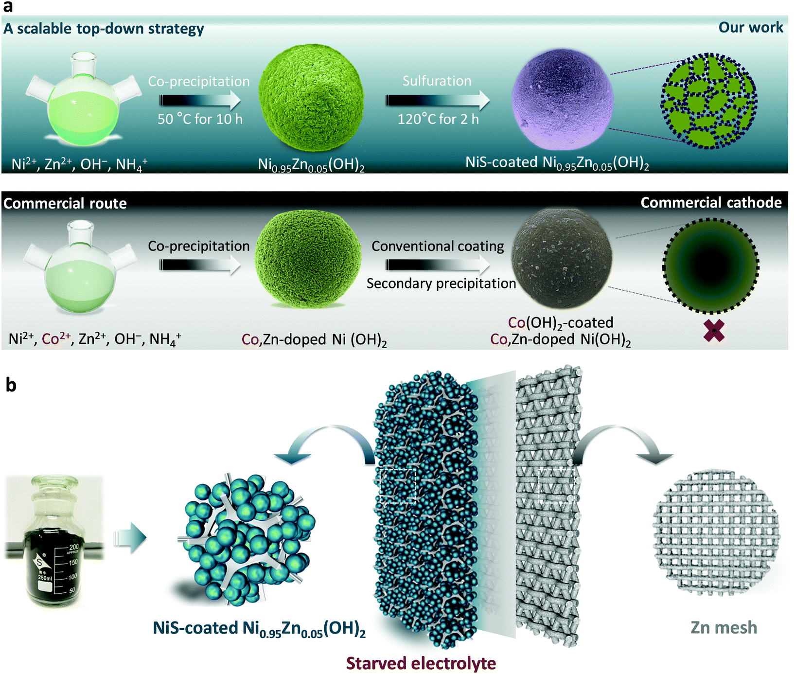 | ||
| Scheme 1 The scalable top-down strategy for application in Ni–Zn batteries. (a) Schematics showing the preparation steps of the top-down strategy compared with the existing commercial route. (b) Electrode configuration and specification of the Ni–Zn battery. The inset shows the industrial viability of the strategy. | ||
Results and discussion
Morphology and structure
The scalable top-down strategy preparation of the NiS-coated Ni0.95Zn0.05(OH)2 microspheres is disclosed in Scheme 1b and Fig. S2 (ESI†). Typical SEM images of the NiS-coated Ni0.95Zn0.05(OH)2 microspheres with different magnifications are shown in Fig. 1a, b, Fig. S3 and S4 (ESI†). The as-prepared samples are composed of well-dispersed homogeneous spherical particles 4–22 μm in diameter, and the average size is 10.6 μm. It can be found that the Ni0.95Zn0.05(OH)2 precursor is composed of spindle nanostructures 50–120 nm in width and 300–400 nm in length (Fig. S4a, ESI†). The spindle nanostructures consist of ultrafine nanodots with an average size of ∼38 nm (Fig. S4b, ESI†). After a facile low-temperature sulfuration process, the spherical feature is well preserved in the NiS-coated Ni0.95Zn0.05(OH)2 (Fig. 1b). Compared to the Ni0.95Zn0.05(OH)2 precursor, densely packed equiaxial nanodots with an average size of ∼7.0 nm (Fig. 1c) can be observed clearly on the surface of the porous architecture (Fig. S4c and d, ESI†). To further identify the relationship between NiS and Ni0.95Zn0.05(OH)2, TEM and HRTEM images were recorded. Fig. 1d and e depicts a thin coating layer of NiS nanodots (5–15 nm) onto Ni0.95Zn0.05(OH)2, which is different from the pure Ni0.95Zn0.05(OH)2 structure in Fig. S5 (ESI†). Two sets of lattice fringes can be observed in Fig. 1e, where the lattice spacing of 0.233 nm in the core area is in good agreement with the (101) plane of β-Ni(OH)2 phase, and the lattice spacing of 0.299 nm at the shell layer corresponds to the (101) plane of NiS phase. The corresponding energy dispersive X-ray spectroscopy (EDS) mapping (Fig. 1f) shows the homogeneous distribution of Ni, Zn and S elements in NiS-coated Ni0.95Zn0.05(OH)2. It should be pointed out that the derived electrode is free of costly cobalt (Fig. 1f), which is different from the commercial Ni(OH)2 cathode material (Fig. S6, ESI†). Herein, instead of Co, our elaborate NiS-coating layer should result in high conductivity (5.5 × 10⁴ S cm−1) and improved oxygen evolution overvoltage.23,24 Thereby, high-cost Co can be completely eradicated by our top-down strategy. More importantly, the tap density of NiS-coated Ni0.95Zn0.05(OH)2 remains as high as 2.30 g cm−3 (measured in Fig. S2a, ESI†) owing to the uniform crystallite sizes, compact microscale structures and wide particle size distribution.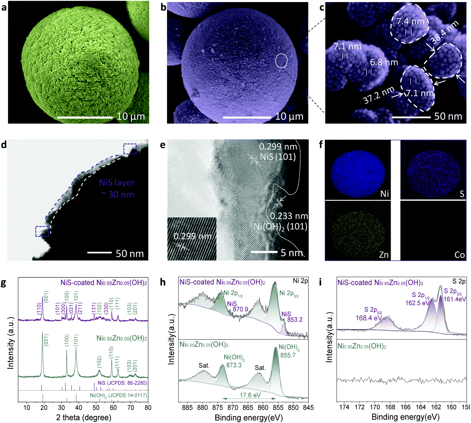 | ||
| Fig. 1 Morphology and structure characterization of the NiS-coated Ni0.95Zn0.05(OH)2 microspheres. (a) SEM image of the Ni0.95Zn0.05(OH)2 precursor. (b and c) SEM images of NiS-coated Ni0.95Zn0.05(OH)2 microspheres. (d and e) TEM and HRTEM images. The inset in (e) is the enlarged view of (d). (f) EDS mapping. (g–i) XRD, XPS Ni 2p and XPS S 2p spectra of the Ni0.95Zn0.05(OH)2 precursor and NiS-coated Ni0.95Zn0.05(OH)2 microspheres. | ||
The X-ray powder diffraction (XRD) results in Fig. 1g further confirm the above transformation. In the Ni0.95Zn0.05(OH)2 precursor, all the diffraction peaks match well with the standard XRD pattern of hexagonal β-Ni(OH)2 (JCPDS: 14-0117). After sulfuration, new diffraction peaks indexed to the hexagonal phase NiS (JCPDS: 86-2280) appear. Further inductively coupled plasma-optical emission spectrometry (ICP-OES) analysis confirms the total content of NiS ca. 9.78 wt% in the sample. Additionally, XPS spectra were acquired and fitted by a Gaussian simulation method to obtain further information on the changes in the elemental composition and valence state of surface elements between the Ni0.95Zn0.05(OH)2 and NiS-coated Ni0.95Zn0.05(OH)2 microspheres (Fig. S7, ESI† and Fig. 1h, i). The Ni 2p high-resolution spectrum in the Ni0.95Zn0.05(OH)2 sample shows two strong spin–orbit peaks at 873.3 eV (Ni 2p1/2) and 855.7 eV (Ni 2p3/2), together with two corresponding satellite peaks (Fig. 1h). The spin-energy separation of Ni 2p1/2 and Ni 2p3/2 is 17.6 eV, corresponding well to Ni(OH)2 phase.40 After surface coating, a noticeable peak of 853.2 eV appears, which belongs to the characteristic peak for NiS.41 This can be further proved by the S 2p high-resolution spectrum, where three peaks can be observed (Fig. 1i). The spectrum peaks located at 161.4 and 162.5 eV correspond to the binding energies of S 2p3/2 and S 2p1/2 levels, which can be ascribed to the S2− signal.3,23 Meanwhile, the peak at 168.4 eV is the signal of SO42−, which suggests partial oxidation of the surface S2− to sulfate.3,23
To disclose the universality of the NiS coating, the inner structure of the microspheres was characterized at the cross-section. As shown in Fig. 2a, the inner structure of the microspheres is very compact, which is beneficial for high tap density. Densely packed equiaxial nanodots with an average size of ∼7.0 nm were also observed in the bulk of the microspheres (Fig. 2b), forming a radial network of microstructures with a large number of interconnected mesopores. In comparison, these pores were not observed in the bulk of the Ni0.95Zn0.05(OH)2 precursor (Fig. S8, ESI†). The corresponding EDS mapping and linear scanning were conducted (Fig. 2b and Fig. S9, ESI†). The homogeneous distribution of Ni, O, S, and Zn elements at the cross-section further confirms the infiltrative coating of NiS. The formation mechanism of the NiS layer together with the interconnected mesopores was briefly analyzed. As expected, S2− permeated into the interstices of the crystallite when soaking the Ni0.95Zn0.05(OH)2 microspheres in Na2S solution. Hence, the surface part of Ni(OH)2 was transformed into a thin NiS coating layer.
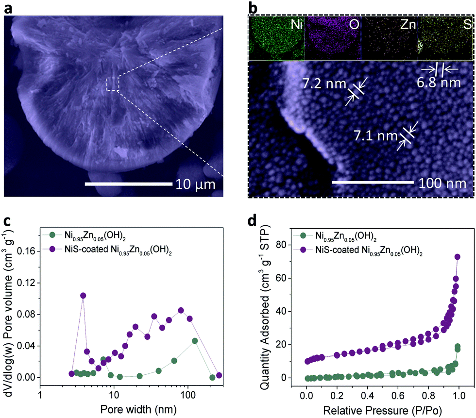 | ||
| Fig. 2 Inner structure characterization of the NiS-coated Ni0.95Zn0.05(OH)2 microspheres. (a and b) Cross-section SEM images of the inner structure of the NiS-coated Ni0.95Zn0.05(OH)2 at (a) low and (b) high magnification. The inset in b is the corresponding EDS mapping of the cross-section. (c) Pore-size distribution plots calculated by the Barrett–Joyner–Halenda (BJH) method from the adsorption branch isotherms. (d) Corresponding nitrogen adsorption–desorption isotherms. | ||
Moreover, on the basis of the Kirkendall effect, abundant mesopores were produced due to the discrepancy in the diffusion rate between metal cations and sulfide anions during the sulfidation process.42 This deduction can be further confirmed by the graded S distribution of the elemental composition in Fig. S10 and Table S2 (ESI†), which further proves an infiltrative top-down NiS coating process. The BET results in Fig. 2c and d reveal the existence of mesopores (∼3.6 nm) after the sulfidation process. As a result, the specific surface area of the NiS-coated Ni0.95Zn0.05(OH)2 (56.4 m2 g−1) is much higher than that of Ni0.95Zn0.05(OH)2 (15.6 m2 g−1). It was predicted that the elaborate microstructures and compositions of the NiS-coated Ni0.95Zn0.05(OH)2 cathode would benefit its electrochemical performance in Ni–Zn batteries.
A best practice of sealed and starved Ni–Zn battery design
To evaluate the practical application of the NiS-coated Ni0.95Zn0.05(OH)2 microspheres as a cathode material for advanced Ni–Zn batteries, a deliberately designed sealed device (schematic in Fig. 3a and photograph in Fig. 3b) was used, together with some on-purpose strategies that approach the possibility of commercialization. A binder-free Zn mesh was used here as a 3D porous anode to suppress dendrite growth.9,11,43 To further suppress the dissolution and corrosion of the Zn anode, an electrolyte of 4 M KOH + 2 M KF + 1 M K2CO3 with saturated ZnO was adopted (as discussed in Fig. S12, ESI†).44,45 The Zn anode stability tests and relevant discussions can be found in the ESI,† Fig. S13 and S14. It is known that in practical applications of high-energy batteries, the loading of inactive materials must be minimized to provide more electroactive components into a fixed electrode volume. In this work, we used an industrial formula (active material:conductive agent:binder = 96:3:1), a starved electrolyte design, and ultrahigh mass loading of the active material at 80 mg cm−2 to prepare the electrode.
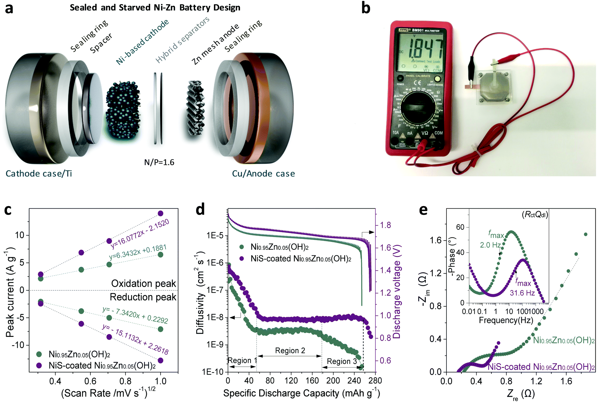 | ||
| Fig. 3 Kinetics analysis of the sealed and starved Ni–Zn design. (a) Schematic of the Ni–Zn demo battery design with high mass loading of 80 mg cm−2. (b) Photograph of the designed cell and high open-circuit voltage of 1.847 V of the Ni–Zn cell. (c) Linear correlation between the peak current and the square root of the scan rate. (d) GITT curves and diffusivity versus DOD. (e) Nyquist plots. Inset: Bode plots of the (RctQdl) parallel components. | ||
The cyclic voltammetry (CV) curves at a slow rate of 1 mV s−1 (Fig. S15a and b, ESI†) show a couple of cathodic and anodic peaks, corresponding to the proton insertion and extraction process of the NiOOH/Ni(OH)2 redox reaction, respectively. The redox peak current densities (i) against the square root of the scan rates (ν1/2) are plotted in Fig. 3c. The linear relationship suggests that the redox reaction is a semi-infinite diffusion-controlled process.28 The resulting proton diffusivity (DH) values for the NiS-coated Ni0.95Zn0.05(OH)2 and Ni0.95Zn0.05(OH)2 are 2.94 × 10⁻⁷ and 4.58 × 10⁻⁸ cm2 s−1, respectively. This result discloses the superior proton diffusion of NiS-coated Ni0.95Zn0.05(OH)2, which can be further confirmed by the GITT tests in Fig. 3d. Interestingly, the NiS-coated Ni0.95Zn0.05(OH)2 electrode is capable of maintaining high proton DH at 95% depth of discharge (DOD) (Region 1 to 3), while an obvious DH drop can be observed for Ni0.95Zn0.05(OH)2 when the DOD exceeds 70% (only Regions 1 and 2).
The Nyquist plot in Fig. 3e shows a smaller Ohm resistance (ROhm) of the NiS-coated Ni0.95Zn0.05(OH)2 (0.1561 Ω) compared with that of the pure Ni0.95Zn0.05(OH)2 (0.2261 Ω). Further electrical conductivity tests prove the high conductivity of NiS-coated Ni0.95Zn0.05(OH)2 (6.1 × 10⁻³ S cm−1), which is around four orders of magnitude higher than that of the Ni0.95Zn0.05(OH)2 precursor (3.4 × 10⁻⁷ S cm−1), and even 200 times larger than that of commercial Co(OH)2-coated Co,Zn-doped Ni(OH)2 (2.5 × 10⁻⁵ S cm−1). In addition, the charge-transfer resistance (Rct) for the NiS-coated Ni0.95Zn0.05(OH)2 (0.3514 Ω) is almost half that of Ni0.95Zn0.05(OH)2 (0.677 Ω), which can be ascribed to the surge in electroactive sites via the introduction of NiS. Furthermore, as shown in the inset of Fig. 3e, the NiS-coated Ni0.95Zn0.05(OH)2 shows a fast charge response, with a characteristic frequency (fmax) of 31.6 Hz (31.62 ms); this is ca. 15-fold greater than that of Ni0.95Zn0.05(OH)2 (2.0 Hz, 501.2 ms). Therefore, the top-down strategy-derived electrode possesses overwhelming kinetics advantages in both proton diffusion and charge response due to the intrinsic structure optimization (abundant mesopores and electrolyte feasibility) and the introduction of ultrafine conductive NiS doping (Fig. 2).
Undoubtedly, achieving high specific capacities while considering gravimetric, areal and volumetric conditions is the basic requirement for practical application.1,46,47 In previous work, designing binder-free nanoarrays15,18,22,23,28 and/or hybridising with abundant carbon materials10,20,24 was found to be effective to realize high gravimetric specific capacity and rate capability in Ni nanoarchitecture-based cathodes; however, these methods are only applicable in low-mass-loading electrodes. As comprehensively listed in Table S1 (ESI†), the mass loading was generally extremely limited below 2 mg cm−2, which cannot meet the requirements of practical application (vs. 28 mA h cm−2 in a commercial BPI brand Ni–Zn battery). For instance, the mass loading of P-NiCo2O4−x nanosheets is only 0.66 mg cm−2,28 and that of a NiCo-DH electrode is only 1.56 mg cm−2.15 We know that it is challenging to fabricate high-loading electrodes, as a thick electrode (>300 μm) is liable to result in fracture and delamination after coating and drying.48 Moreover, thick electrodes with high mass loadings will cause serious polarization during charge/discharge,47 which will deteriorate the high-rate and cycling behaviours of the electrode. Dai et al.10 attempted to achieve a high-mass loading (46 mg cm−2) NiAlCo LDH/CNT cathode in their ultrafast Ni–Zn batteries. The electrode exhibited a high discharge capacity of 360 mA h g−1 at 1 mg cm−2 while retaining only 240 mA h g−1 at 46 mg cm−2. After compressing to 500 μm in thickness, the maximum compacted density of their electrodes was only 0.92 g cm−3, which is not suitable to fulfill the requirements of industrial applications (>2.5 g cm−3).
In this study, owing to the high density of the slurry with NiS-coated Ni0.95Zn0.05(OH)2 microspheres, it is easy to fabricate a cathode possessing a mass loading as high as 160 mg cm−2. After compressing to 560 μm in thickness (Fig. S16, ESI†), the compacted density of the electrode reaches 2.86 g cm−3, which is much higher than those of reported nano-porous materials.20,24Fig. 4a, b and Fig. S15c (ESI†) illustrate the discharge behaviour of the cathodes with different mass loadings. It can be found that both the Ni0.95Zn0.05(OH)2 and NiS-coated Ni0.95Zn0.05(OH)2 electrodes achieve a high discharge capacity of over 270 mA h g−1 at a low mass loading of 26 mg cm−2, which is close to the theoretical capacity of 289 mA h g−1 based on single-electron transfer of NiOOH/Ni(OH)2. However, the NiS-coated Ni0.95Zn0.05(OH)2 electrode presents much better gravimetric and areal specific discharge capacities than that of the Ni0.95Zn0.05(OH)2 electrode at high mass loadings. Specially, at a mass loading of 160 mg cm−2, benefitting from the significantly enhanced electrode kinetics (Fig. S17, ESI†), the specific capacity of NiS-coated Ni0.95Zn0.05(OH)2 is much higher than that of Ni0.95Zn0.05(OH)2 (258.1 mA h g−1vs. 208 mA h g−1). As a result, the NiS-coated Ni0.95Zn0.05(OH)2 cathode can be scaled up linearly to a high areal capacity of 41.3 mA h cm−2 (Fig. 4b), which is over 40 times higher than those of reported nano-architectured electrodes, as shown in Table S1 (ESI†).
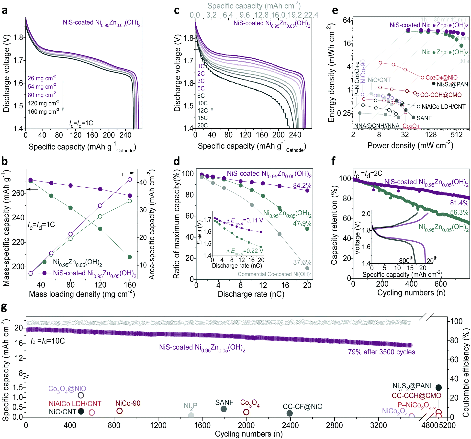 | ||
| Fig. 4 Electrochemical performance of the sealed and starved Ni–Zn batteries. (a) Galvanostatic discharge profiles of the NiS-coated Ni0.95Zn0.05(OH)2 at different material loadings. (b) Gravimetric and areal specific discharge capacity comparison of the different material loadings. (c) Galvanostatic discharge profiles of the NiS-coated Ni0.95Zn0.05(OH)2 at different rates with a mass loading of 80 mg cm−2. (d) Rate performance comparison with a mass loading of 80 mg cm−2. The inset shows the midpoint voltage as a function of current density. (e) Ragone plots showing a comprehensive comparison of the areal energy density and power density with reported results. (f) Cycling performance at 2C. (g) Long-term cycling performance at 10C of NiS-coated Ni0.95Zn0.05(OH)2 in comparison with the state-of-the-art alkaline Zn batteries. | ||
Fig. 4c, d and Fig. S15d (ESI†) display the rate capability of the Ni–Zn batteries at rates from 1C (22.4 mA cm−2) to 20C (448 mA cm−2). It should be noted that the mass loading of the cathode is fixed at a high level of 80 mg cm−2 in a later part of the manuscript for practical evaluation. At 1C, the discharge capacity and plateau of NiS-coated Ni0.95Zn0.05(OH)2 (266.6 mA h g−1 with middle discharge voltage (Emid,d) of 1.71 V) are slightly higher than that of Ni0.95Zn0.05(OH)2 (248.2 mA h g−1 with Emid,d 1.69 V). Particularly, the difference is significantly amplified at high rates, i.e., 226.1 mA h g−1 at 20C for the NiS-coated Ni0.95Zn0.05(OH)2//Zn battery (around twice the capacity of the Ni0.95Zn0.05(OH)2//Zn battery). In addition, the sealed and starved NiS-coated Ni0.95Zn0.05(OH)2//Zn battery shows milder voltage polarization at higher rates, with a smaller substantial voltage loss (ΔEmid,d) of 0.1162 V vs. 0.2196 V of the pure Ni0.95Zn0.05(OH)2//Zn battery. As calculated in Fig. 4d, the NiS-coated Ni0.95Zn0.05(OH)2//Zn battery maintains 84.2% of its maximum capacity at 20C, which is fairly applicable to replace the commercial Co-coated Ni(OH)2 high-rate cathode (39.9% at 20C, Fig. S18, ESI†). Furthermore, attributed to the lower voltage polarization and suppression of OER (Fig. S15b, ESI†), the NiS-coated Ni0.95Zn0.05(OH)2//Zn battery also presents excellent high-rate chargeability (Fig. S19, ESI†); it can be fully charged at 20C within 3 min.
As shown in the gravimetric Ragone plots in Fig. S20 and computational details in Table S3 (ESI†), both high energy and power densities (300 W h kg−1 at 315 W kg−1 and 237 W h kg−1 at 5870 W kg−1) can be simultaneously achieved based on the total mass of the active materials. These values outperform reported Ni–Zn batteries and most developed aqueous batteries, such as CMO//ZnO@C-Zn (235 W h kg−1 at 1700 W kg−1),49 Ni(OH)2//FeOx/graphene (141 W h kg−1 at 1600 W kg−1),50 Ni(OH)2//MH (73.5 W h kg−1 at 2000 W kg−1),51 β-MnO2//Zn (110 W h kg−1 at 5910 W kg−1),52 NaV3O8·1.5H2O//Zn (110 W h kg−1 at 2474 W kg−1),53 LiCoO2/Mo6S8 (120 W h kg−1 at 60 W kg−1),54 Na4Fe3(PO4)2(P2O7)//NaTi2(PO4)3 (20 W h kg−1 at 276 W kg−1),55 and KFeMnHCF//PTCDI (67 W h kg−1 at 1612 W kg−1).56 It should be noted that in most reported alkaline Zn batteries, the areal energy density is lower than 2 mW h cm−2;15–29 therefore, the real gravimetric energy density on the basis of the whole battery is rarely reported. Here, considering the weight of the current collectors, the gravimetric energy density of the battery is around 212 W h kg−1 (80 mg cm−2; the negative/positive (N/P) capacity equals 1.6), and it further significantly increased to 260 W h kg−1 at a high mass loading of 160 mg cm−2 and N/P = 1.2. Due to the ultrahigh loading density and excellent electrochemical activity of the NiS-coated Ni0.95Zn0.05(OH)2 cathode, ultrahigh areal energies and power densities (36.5 mW h cm−2 at 38 mW cm−2, 29 mW h cm−2 at 715 mW cm−2) were achieved. On the basis of a comprehensive summary (as compared in Fig. 4e and summarized in Table S4, ESI†), to the best of our knowledge, this is the highest areal energy/power density achieved among reported aqueous batteries to date.
Long lifespan is vital for practical application of Ni–Zn batteries. As shown in Fig. 4f, the NiS-coated Ni0.95Zn0.05(OH)2//Zn battery exhibits excellent cycling performance, with a high capacity retention of 81.4% after 800 cycles at 2C and 100% DOD. High capacities of 215 mA h g−1 and 17.2 mA h cm−2 could be maintained. However, only 56.3% capacity retention can be observed in the Ni0.95Zn0.05(OH)2//Zn battery. It is reasonable that the NiS coating layer possesses excellent electrochemical reversibility in the alkaline electrolyte (Fig. S21, ESI†),23,24 and the Kirkendall effect endows the NiS-coated Ni0.95Zn0.05(OH)2 microsphere with abundant mesopores, which can efficiently enhance the structural tolerance to survive volume expansion with preserved morphology after repeated proton insertion and extraction (Fig. S21 and S22, ESI†). As shown in Fig. 4g and Fig. S23 (ESI†), the designed battery is capable of undergoing 3500 full charge/discharge cycles at 10C (fully charged within 6 min) with a high coulombic efficiency of 98.6% while maintaining 15.4 mA h cm−2 (79%) capacity.
Transient power evaluation
Note that aqueous batteries have been widely used in hybrid electric vehicles (HEVs) and starting–lighting–ignition (SLI), where the specific power is far more important than the specific energy due to the requirement of a high-power delivery with low DOD.9,39 To further check the advantages of our Ni–Zn aqueous batteries in practical applications, their transient power performance was evaluated. Typical pulse and rest tests of the battery were conducted in a single cell (shown in Fig. 5a). It can be found that the NiS-coated Ni0.95Zn0.05(OH)2//Zn battery presents a higher pulse voltage. During a transient discharge process (e.g., 30 s, inset in Fig. 5b), the total polarization can be divided into the following two parts: an abrupt drop from open-circuit-voltage (OCV) to initial-closed-circuit-voltage (ICCV), i.e., the IR drop, and a gradual drop from ICCV to t second working voltage (Et). Because the former cannot be utilized for power delivery, the IR drop becomes a decisive index to evaluate the transient power output. The linear relationship between the IR drop and Id can be found in Fig. 5b. The IR drop (i.e. IR ∼ Id slope) is related to ohmic polarization (ROhm) according to Ohm's law and/or charge-transfer polarization (Rct) according to the Bulter-Volmer equation (I0 ∝ Rct−1).57 Obviously, the NiS-coated Ni0.95Zn0.05(OH)2//Zn battery presents a much lower IR ∼ Id slope than the Ni0.95Zn0.05(OH)2//Zn battery. The result is coincident with the ROhm and Rct results from EIS (Fig. 3e), confirming the availability of facile sulfuration technology in enabling high-power delivery.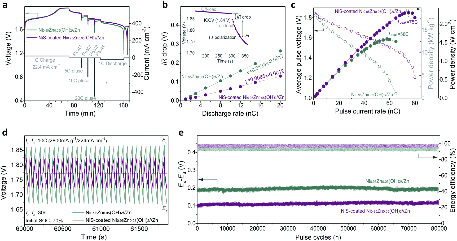 | ||
| Fig. 5 Transient power performance of the sealed and starved Ni–Zn batteries. (a) Typical pulse and rest test of the batteries. (b) Linear relationship between IR drop and Id. Inset: Typical off-load and on-load voltages of the battery, where the OCV (1.87 V) and ICCV (1.84 V) can be clearly observed. The gray dashed lines are the fitted results. (c) V ∼ i correlation and power output of the batteries. (d) Voltage profiles during the pulse charge–discharge cycles at an ultrahigh current of 10C. The initial SOC of the materials is 70%. (e) Voltage difference and energy efficiency between the pulse charge and pulse discharge during cycles. | ||
Fig. 5c illustrates the specific power (P) delivery and the V ∼ i curves of the batteries, where P values are calculated via the equation P = Un,t × In (where In and Un,t are the discharge current density of n mA g−1 and the corresponding average output voltage from ICCP to Et, respectively).58 After 30 s transient polarization, Un,t of each electrode drops almost linearly with increasing In; thus, a peak power (Ppeak) and peak current (Ipeak) can be observed. Compared to Ni0.95Zn0.05(OH)2//Zn, the NiS-coated Ni0.95Zn0.05(OH)2//Zn battery shows a significantly lower voltage drop and higher Ipeak of 75C (58C for Ni0.95Zn0.05(OH)2//Zn). Encouragingly, an ultrahigh instantaneous power delivery, i.e., Ppeak of 18.8 kW kg−1 (2.30 W cm−2 or 45.92 kW L−1) can be achieved, while that of the Ni0.95Zn0.05(OH)2//Zn battery is only 13.0 kW kg−1 (1.58 W cm−2 or 31.68 kW L−1). This value outperforms most batteries, even supercapacitors (SCs), such as CC-CF@NiO//CC-CF@ZnO battery (17.90 kW kg−1, 0.54 kW L−1),22 Co–Zn battery (12.6 kW kg−1, 0.42 kW L−1),49 Ni-MH battery (4.8 kW kg−1, 6.1 kW L−1),59 Ni–Fe battery (3.2 kW kg−1, 1.5 kW L−1),60 MnO2–Zn battery (9.45 kW kg−1),61 Li-ion battery (5.1 kW L−1),62 and FeOF/Ni(OH)2-AC SCs (2.34 kW kg−1).63
Fig. 5d shows the high-rate pulse charge–discharge performance, where the batteries operate in so-called ‘charge sustaining’ mode, i.e., being transiently charged-discharged at ultrahigh current (10C) within the default state of the charge (SOC) limits (60–80%). This is an important operating mode of batteries for HEVs, where the main purpose of the battery is to store the energy from regenerative braking and assist acceleration at startup.9,39 In grid-scale power applications, such as frequency and voltage regulation, power quality, renewable generation smoothing and ramp-rate control, a battery system generally functions as a “buffer”, i.e. it decouples the generators and their loads by comparatively short periods of absorbing or discharging energy (seconds to minutes) in response to the needs of the grid.39 As shown in Fig. 5d, the NiS-coated Ni0.95Zn0.05(OH)2//Zn battery shows a small pulse polarization in the range of a low discharge pulse voltage (Ed, 1.74) and a high charge pulse voltage (Ec, 1.84 V). The energy efficiency (i.e., energy output/input) of the NiS-coated Ni0.95Zn0.05(OH)2//Zn (97.3%) is also higher than that of the Ni0.95Zn0.05(OH)2//Zn (92.9%) during the high-current pulses (Fig. S24, ESI†). Furthermore, to validate the stability of the batteries during high-current pulses, the voltage difference ΔE (Ec − Ed) and energy efficiency are plotted against the cycles in Fig. 5e. Impressively, the ΔE and energy efficiency values display no signal of attenuation after ultralong high-current pulses of 80000 cycles. Furthermore, the NiS-coated Ni0.95Zn0.05(OH)2//Zn battery can hold its initial capacity after long high-current pulse cycles (Fig. S24, ESI†), indicating excellent anti-self-discharge behaviour. These results demonstrate that our elaborate Ni–Zn batteries are extremely suitable for high-power charge–discharge pulse applications, serving as a potential alternative to the existing valve-regulated lead-acid (VRLA) batteries, which have dominated the SLI application market for the past 100 years.9
Scale-up and 3.5 A h pouch-type Ni–Zn battery
The exceptional performance of the Ni–Zn homemade coin-scale batteries stimulated us to develop high-energy pouch-type full batteries, which were fabricated in ambient air without any complicated procedures or protection (see the ESI†). Fig. 6a schematically shows the battery configuration consisting of four whole sets of anode–separator–cathode stacks. After systematic optimization, Ni–Zn pouch batteries with 3.5 A h were obtained (details in Fig. S25 and Table S5, ESI†) with controlled N/P within 1.2 to 2.0. Remarkably, our Ni–Zn pouch batteries present excellent high-rate ability, with N/P of 2.0 (Fig. S26a, ESI†); they output 87% of their rate capacity with a delivery voltage over 1.5 V at 8C (28 A). Even working at 12C (42 A), the capacity of the battery remains as high as 2280 mA h, with a 30 s transient power density of 1888 W kg−1. Furthermore, compared with a commercial Ni–Zn battery (BPI, AA, 1500 mA h, 2500 mW h), our Ni–Zn pouch batteries process much better cycling performance of 89.4% capacity retention after 420 cycles vs. 8.2% for the commercial Ni–Zn battery (Fig. 6b).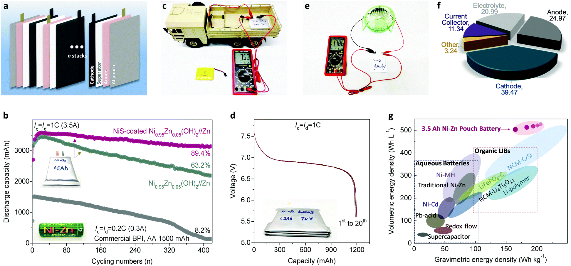 | ||
| Fig. 6 Electrochemical performance of the 3.5 A h pouch-type Ni–Zn battery. (a) Schematic of the cell configuration with anode–separator–cathode stacks. (b) Cycling performance in comparison with the commercial BPI Ni–Zn battery. The N/P ratio is set as 2.0. (c) A digital photo of a 7 V, 1.2 A h Ni–Zn series battery powering a small-scale electric vehicle (rated power of 10 W and operating voltage ≥6 V). (d) The 1st to 20th discharge profiles of the 7 V battery at 1C. (e) Acupuncture test showing the high safety of the soft-package battery showing a voltage of 1.786 V in powering a fan load (rated power >3 W). (f) The component proportion of the 3.5 A h Ni–Zn pouch battery showing an ultrahigh loading of active materials in a whole device. (g) Comparison of our elaborate Ni–Zn pouch cells with other commercial battery technologies in terms of volumetric and gravimetric energy density. The spots represent controllable designs with different N/P ratios and amounts of electrolyte. | ||
For scale-up application, a 7 V, 1.2 A h Ni–Zn battery was fabricated by simply connecting four single cells in series to power a small-scale electric vehicle (Video S1, ESI;† the electric car requires a power >10 W and operating voltage ≥6 V). As shown in Fig. 6c, d and Fig. S27 (ESI†), the battery presents an open-circuit voltage of 7.53 V and a capacity of 1196 mA h with a stable average-discharge-voltage of 6.88 V. In the battery safety evaluation, we confirmed that the as-fabricated Ni–Zn battery possesses impressive safety tolerance against fire, explosion and/or poisonous smoke when struck, flame-treated, and impaled in open-air conditions (Video S2, ESI†). Moreover, it can work well in powering a fan load with a rated power >3 W after the acupuncture test (Fig. 6e). These results demonstrate that the Ni–Zn battery is extraordinarily safe and reliable, even under some extreme conditions.
Most importantly, as shown in Fig. 6f and g, the 3.5 A h full cell delivers an energy density of 165 W h kg−1 based on the total weight of the whole battery (including the electrodes, separators, electrolyte, and packages, see Fig. S25 and Table S5, ESI†). To the best of our knowledge, this value outperforms other available aqueous batteries (e.g. VRLA: 30–50 W h kg−1, Ni–Cd: 50–70 W h kg−1, Ni–MH: 60–110 W h kg−1 and Ni–Zn: 60–100 W h kg−1), and is comparable to advanced organic Li-ion batteries (120–200 W h kg−1). Additionally, when the N/P drops to 1.2, the energy density of the whole battery is as high as 206.9 W h kg−1 (Fig. 6g). Meanwhile, owing to the ultra-high compact density of the cathode material (2.8–3.0 g cm−3) and the ultra-high specific volumetric capacity of Zn metal foam (5855 mA h cm−3), the volumetric energy density of our soft-packed full battery reaches 506 W h L−1 at a reasonable N/P ratio of 2.0, which exceeds that of current commercialized batteries. Considering the low cost of the Co-free cathode, Zn metal anode and KOH aqueous electrolyte, our Ni–Zn battery achieves a significantly lower cost of about US $32.8 per kW h (see details in Tables S6 and S7, ESI†) compared with lead-acid batteries (US $150–500 per kW h), Ni–MH batteries (US $200–729 per kW h), and Li-ion batteries (US $300–2500 per kW h).2,64
Conclusions
To correct the inadvertent biases between the current practical application of Ni–Zn batteries with poor gravimetric energy and literature-reported nano-architectured materials with low volumetric energy/power, herein, we developed a scalable top-down strategy toward cost-effective preparation of ultra-dense Co-free microspheres for practical application in Ni–Zn batteries. Compared to the traditional routes to Co-containing Ni(OH)2 cathodes, our exploration produces significant environmental and economic benefits of 30–143% cost-savings. Due to the anion exchange and Kirkendall effect, this commercially viable technology endows the whole microscale matrix with enhanced electrochemical activity and fast proton-diffusion kinetics. We demonstrate for the first time a best practice for systematical measuring of aqueous batteries and electrode materials in a more practical metric. As a result, the Ni–Zn demo battery can deliver an imposing areal capacity of 41.3 mA h cm−2, ultralong lifespan (80000 transient pulse cycles), and power response (715 mW cm−2) under the conditions of high mass loading (80 mg cm−2) and tap density (2.30 g cm−3). Furthermore, the elaborate commercial-grade 3.5 A h Ni–Zn pouch battery possesses unprecedented energy density of 165 W h kg−1 gravimetrically and 506 W h L−1 volumetrically, and it is safe and affordable (US $32.8 per kW h). These findings are a fillip for development of aqueous batteries with high energy and power density and will be of immediate benefit for next-generation reliable, affordable and scalable energy storage.
Conflicts of interest
There are no conflicts to declare.Acknowledgements
The authors acknowledge the financial support from the National Natural Science Foundation of China (No. 21603154), the Science and Technology Support Program of Sichuan Province (No. 2017RZ0033), and the Fundamental Research Funds for the Central Universities (No. 2012017yjsy229). This work was also supported by the Australian Research Council Discovery Projects (DE200101244). The authors would like to thank the INELT of SCU for microscopy work and Prof. Yingming Zhu for his assistance in electron microscopy. The authors would like to thank Ceshigo (http://www.ceshigo.com) for the TEM and XPS characterization.References
- D. Chao, W. Zhou, F. Xie, C. Ye, H. Li, M. Jaroniec and S.-Z. Qiao, Sci. Adv., 2020, 6, eaba4098 CrossRef PubMed.
- Z. P. Cano, D. Banham, S. Ye, A. Hintennach, J. Lu, M. Fowler and Z. Chen, Nat. Energy, 2018, 3, 279–289 CrossRef.
- J. Li, W. Zhou, D. Zhu, J. He, C. Wu and Y. Chen, Chem. Eng. J., 2020, 379, 122204 CrossRef CAS.
- Y. Ding, Z. P. Cano, A. Yu, J. Lu and Z. Chen, Electrochem. Energy Rev., 2019, 2, 1–28 CrossRef CAS.
- K. Liu, Y. Liu, D. Lin, A. Pei and Y. Cui, Sci. Adv., 2018, 4, eaas9820 CrossRef PubMed.
- G. Zubi, R. Dufo-López, M. Carvalho and G. Pasaoglu, Renewable Sustainable Energy Rev., 2018, 89, 292–308 CrossRef.
- M. Song, H. Tan, D. L. Chao and H. J. Fan, Adv. Funct. Mater., 2018, 28, 1802564 CrossRef.
- D. Chao, C. Ye, F. Xie, W. Zhou, Q. Zhang, Q. Gu, K. Davey, L. Gu and S. Z. Qiao, Adv. Mater., 2020, 2001894 CrossRef CAS PubMed.
- J. F. Parker, C. N. Chervin, I. R. Pala, M. Machler, M. F. Burz, J. W. Long and D. R. Rolison, Science, 2017, 356, 415–418 CrossRef CAS PubMed.
- M. Gong, Y. Li, H. Zhang, B. Zhang, W. Zhou, J. Feng, H. Wang, Y. Liang, Z. Fan, J. Liu and H. Dai, Energy Environ. Sci., 2014, 7, 2025–2032 RSC.
- W. Lu, C. Xie, H. Zhang and X. Li, ChemSusChem, 2018, 11, 3996–4006 CrossRef CAS PubMed.
- D. Chao, C. R. Zhu, M. Song, P. Liang, X. Zhang, N. H. Tiep, H. Zhao, J. Wang, R. Wang, H. Zhang and H. J. Fan, Adv. Mater., 2018, 30, 1803181 CrossRef PubMed.
- H. F. Li, L. T. Ma, C. P. Han, Z. F. Wang, Z. X. Liu, Z. J. Tang and C. Y. Zhi, Nano Energy, 2019, 62, 550–587 CrossRef CAS.
- M. Huang, M. Li, C. Niu, Q. Li and L. Mai, Adv. Funct. Mater., 2019, 29, 1807847 CrossRef.
- H. Chen, Z. Shen, Z. Pan, Z. Kou, X. Liu, H. Zhang, Q. Gu, C. Guan and J. Wang, Adv. Sci., 2019, 6, 1802002 CrossRef PubMed.
- X. Wang, M. Li, Y. Wang, B. Chen, Y. Zhu and Y. Wu, J. Mater. Chem. A, 2015, 3, 8280–8283 RSC.
- Y. Zeng, Y. Meng, Z. Lai, X. Zhang, M. Yu, P. Fang, M. Wu, Y. Tong and X. Lu, Adv. Mater., 2017, 29, 1702698 CrossRef PubMed.
- Q. Chen, J. Li, C. Liao, G. Hu, Y. Fu, O. K. Asare, S. Shi, Z. Liu, L. Zhou and L. Mai, J. Mater. Chem. A, 2018, 6, 19488–19494 RSC.
- C. Xu, J. Liao, C. Yang, R. Wang, D. Wu, P. Zou, Z. Lin, B. Li, F. Kang and C.-P. Wong, Nano Energy, 2016, 30, 900–908 CrossRef CAS.
- Y. Jian, D. Wang, M. Huang, H.-L. Jia, J. Sun, X. Song and M. Guan, ACS Sustainable Chem. Eng., 2017, 5, 6827–6834 CrossRef CAS.
- Z. Lu, X. Wu, X. Lei, Y. Li and X. Sun, Inorg. Chem. Front., 2015, 2, 184–187 RSC.
- J. Liu, C. Guan, C. Zhou, Z. Fan, Q. Ke, G. Zhang, C. Liu and J. Wang, Adv. Mater., 2016, 28, 8732–8739 CrossRef CAS PubMed.
- L. Zhou, X. Zhang, D. Zheng, W. Xu, J. Liu and X. Lu, J. Mater. Chem. A, 2019, 7, 10629–10635 RSC.
- W. Shi, J. Mao, X. Xu, W. Liu, L. Zhang, X. Cao and X. Lu, J. Mater. Chem. A, 2019, 7, 15654–15661 RSC.
- J. Wen, Z. Feng, H. Liu, T. Chen, Y. Yang, S. Li, S. Sheng and G. Fang, Appl. Surf. Sci., 2019, 485, 462–467 CrossRef CAS.
- J. Li and C. Chen, Mater. Res. Express, 2018, 5, 015502 CrossRef.
- X. Wang, F. Wang, L. Wang, M. Li, Y. Wang, B. Chen, Y. Zhu, L. Fu, L. Zha, L. Zhang, Y. Wu and W. Huang, Adv. Mater., 2016, 28, 4904–4911 CrossRef CAS PubMed.
- Y. Zeng, Z. Lai, Y. Han, H. Zhang, S. Xie and X. Lu, Adv. Mater., 2018, 30, 1802396 CrossRef PubMed.
- H. Zhang, X. Zhang, H. Li, Y. Zhang, Y. Zeng, Y. Tong, P. Zhang and X. Lu, Green Energy Environ., 2018, 3, 56–62 CrossRef.
- J. Betz, G. Bieker, P. Meister, T. Placke, M. Winter and R. Schmuch, Adv. Energy Mater., 2018, 9, 1803170 CrossRef.
- W. Chen, Y. Jin, J. Zhao, N. Liu and Y. Cui, Proc. Natl. Acad. Sci. U. S. A., 2018, 115, 11694–11699 CrossRef CAS PubMed.
- A. Motori, F. Sandrolini and G. Davolio, J. Power Sources, 1994, 48, 361–370 CrossRef CAS.
- M. Oshitani, Y. Sasaki and K. Takashima, J. Power Sources, 1984, 12, 219–231 CrossRef CAS.
- D. Guo, E. Shangguan, J. Li, T. Zhao, Z. Chang, Q. Li, X.-Z. Yuan and H. Wang, Int. J. Hydrogen Energy, 2014, 39, 3895–3903 CrossRef CAS.
- T. Ouchi, K.-H. Young and D. Moghe, Batteries, 2016, 2, 21 CrossRef.
- K. Morimoto, K. Nakayama, H. Maki, H. Inoue and M. Mizuhata, J. Power Sources, 2017, 352, 143–148 CrossRef CAS.
- M. G. Ortiz, S. G. Real and E. B. Castro, Int. J. Hydrogen Energy, 2014, 39, 8661–8666 CrossRef CAS.
- L. Zhang, D. Shi, T. Liu, M. Jaroniec and J. Yu, Mater. Today, 2019, 25, 35–65 CrossRef CAS.
- T. B. Reddy, Linden's handbook of batteries, McGraw-hill, New York, 2011 Search PubMed.
- L. Zhu, W. L. Ong, X. Lu, K. Zeng, H. J. Fan and G. W. Ho, Small, 2017, 13, 1700084 CrossRef PubMed.
- P. Hu, T. Wang, J. Zhao, C. Zhang, J. Ma, H. Du, X. Wang and G. Cui, ACS Appl. Mater. Interfaces, 2015, 7, 26396–26399 CrossRef CAS PubMed.
- L. Shen, L. Yu, H. B. Wu, X. Y. Yu, X. Zhang and X. W. Lou, Nat. Commun., 2015, 6, 6694 CrossRef CAS PubMed.
- D. L. Chao, W. H. Zhou, C. Ye, Q. H. Zhang, Y. G. Chen, L. Gu, K. Davey and S. Z. Qiao, Angew. Chem., Int. Ed., 2019, 58, 7823–7828 CrossRef CAS PubMed.
- P. Bonnick and J. R. Dahn, J. Electrochem. Soc., 2012, 159, A981–A989 CrossRef CAS.
- J. F. Parker, I. R. Pala, C. N. Chervin, J. W. Long and D. R. Rolison, J. Electrochem. Soc., 2016, 163, A351–A355 CrossRef CAS.
- D. Wang, C. Han, F. Mo, Q. Yang, Y. Zhao, Q. Li, G. Liang, B. Dong and C. Zhi, Energy Storage Mater., 2020, 28, 264–292 CrossRef.
- Y. Kuang, C. Chen, D. Kirsch and L. Hu, Adv. Energy Mater., 2019, 9, 1901457 CrossRef.
- Z. Lin, T. Liu, X. Ai and C. Liang, Nat. Commun., 2018, 9, 5262 CrossRef CAS PubMed.
- M. Li, J. Meng, Q. Li, M. Huang, X. Liu, K. A. Owusu, Z. Liu and L. Mai, Adv. Funct. Mater., 2018, 28, 1802016 CrossRef.
- H. Wang, Y. Liang, M. Gong, Y. Li, W. Chang, T. Mefford, J. Zhou, J. Wang, T. Regier, F. Wei and H. Dai, Nat. Commun., 2012, 3, 917 CrossRef PubMed.
- Z. Ren, J. Yu, Y. Li and C. Zhi, Adv. Energy Mater., 2018, 8, 1702467 CrossRef.
- N. Zhang, F. Cheng, J. Liu, L. Wang, X. Long, X. Liu, F. Li and J. Chen, Nat. Commun., 2017, 8, 405 CrossRef PubMed.
- F. Wan, L. Zhang, X. Dai, X. Wang, Z. Niu and J. Chen, Nat. Commun., 2018, 9, 1656 CrossRef PubMed.
- F. Wang, Y. X. Lin, L. M. Suo, X. L. Fan, T. Gao, C. Y. Yang, F. D. Han, Y. Qi, K. Xu and C. S. Wang, Energy Environ. Sci., 2016, 9, 3666–3673 RSC.
- M. H. Lee, S. J. Kim, D. Chang, J. Kim, S. Moon, K. Oh, K.-Y. Park, W. M. Seong, H. Park, G. Kwon, B. Lee and K. Kang, Mater. Today, 2019, 29, 26–36 CrossRef CAS.
- L. Jiang, Y. Lu, C. Zhao, L. Liu, J. Zhang, Q. Zhang, X. Shen, J. Zhao, X. Yu, H. Li, X. Huang, L. Chen and Y.-S. Hu, Nat. Energy, 2019, 4, 495–503 CrossRef CAS.
- D. Zhu, W. Zhou, Z. Tang, Y. Heng, K. Liu, J. Li, L. Xie and Y. Chen, Int. J. Hydrogen Energy, 2019, 44, 15278–15286 CrossRef CAS.
- W. Zhou, D. Zhu, Z. Tang, C. Wu, L. Huang, Z. Ma and Y. Chen, J. Power Sources, 2017, 343, 11–21 CrossRef CAS.
- W. Zhou, D. Zhu, K. Liu, J. Li, C. Wu and Y. Chen, Int. J. Hydrogen Energy, 2018, 43, 21464–21477 CrossRef CAS.
- J. Liu, M. Chen, L. Zhang, J. Jiang, J. Yan, Y. Huang, J. Lin, H. J. Fan and Z. X. Shen, Nano Lett., 2014, 14, 7180–7187 CrossRef CAS PubMed.
- B. Wu, G. Zhang, M. Yan, T. Xiong, P. He, L. He, X. Xu and L. Mai, Small, 2018, 14, 1703850 CrossRef PubMed.
- L. Gao, Y. Jin, X. Liu, M. Xu, X. Lai and J. Shui, Nanoscale, 2018, 10, 7676–7684 RSC.
- M. Wang, Z. Li, C. Wang, R. Zhao, C. Li, D. Guo, L. Zhang and L. Yin, Adv. Funct. Mater., 2017, 27, 1701014 CrossRef.
- M. C. Argyrou, P. Christodoulides and S. A. Kalogirou, Renewable Sustainable Energy Rev., 2018, 94, 804–821 CrossRef.
Footnote |
| † Electronic supplementary information (ESI) available: Supplementary methods, Fig. S1–S27, Tables S1–S7, and supplementary references. See DOI: 10.1039/d0ee01221a |
| This journal is © The Royal Society of Chemistry 2020 |