
A highly reversible neutral zinc/manganese battery for stationary energy storage†
Congxin
Xie
ab,
Tianyu
Li
 a,
Congzhi
Deng
b,
Yang
Song
a,
Huamin
Zhang
a and
Xianfeng
Li
*a
a,
Congzhi
Deng
b,
Yang
Song
a,
Huamin
Zhang
a and
Xianfeng
Li
*a
aDivision of Energy Storage, Dalian National Laboratory for Clean Energy (DNL), Dalian Institute of Chemical Physics, Chinese Academy of Sciences, 457 Zhongshan Road, Dalian 116023, P. R. China. E-mail: lixianfeng@dicp.ac.cn
bUniversity of Chinese Academy of Sciences, Beijing 100039, P. R. China
First published on 17th December 2019
Abstract
Manganese (Mn) based batteries have attracted remarkable attention due to their attractive features of low cost, earth abundance and environmental friendliness. However, the poor stability of the positive electrode due to the phase transformation and structural collapse issues has hindered their validity for rechargeable batteries. Here we presented a highly reversible and stable two electron transfer solid–liquid reaction based on MnO2 and soluble Mn(CH3COO)2(Mn(Ac)2) under neutral medium. Benefiting from the coordination effect of Ac−, the Mn2+ can directly deposit on the electrode in the form of MnO2, which is completely different from other manganese salts (MnSO4 or MnCl2). Compared with the common intercalation mechanism cathode, the dissolution/deposition reaction completely avoided the structure collapse issue, which results in a dramatic improvement in stability. Furthermore, in contrast to the redox pair of Mn3+/Mn2+, the intrinsic problems caused by the disproportionation of Mn3+ can be totally avoided. The proof of concept can be confirmed by a neutral Zn–Mn flow battery with an optimized electrolyte. The MnO2 could be perfectly deposited on the graphite fiber with an areal capacity of 20 mA h cm−2, which is the highest value ever reported. Unlike the alkaline electrolytes, a neutral flow system can effectively avoid the zinc dendrite issues. As a result, a Zn–Mn flow battery demonstrated a CE of 99% and an EE of 78% at 40 mA cm−2 with more than 400 cycles. Combined with excellent electrochemical reversibility, low cost and two-electron transfer properties, the Zn–Mn battery can be a very promising candidate for large scale energy storage.
Broader contextOver the last few decades, manganese (Mn) based batteries have gained remarkable attention due to their attractive natures of abundance in the earth, low cost and environmentally friendliness. However, the phase transformation and structural collapse issue of manganese based electrodes and the side reaction of Mn3+ disproportionation make a very poor cycle life of Zn–Mn rechargeable batteries. Herein, we present a reversible and stable neutral liquid–solid reaction of Mn2+/MnO2via the coordination effect of CH3COO− on Mn2+. In the design, Mn(CH3COO)2 (Mn(Ac)2) can deposit on the positive electrode directly in the form of MnO2 without the generation of Mn3+, which completely inhibits the disproportionation side reaction. Compared with the common intercalation/de-intercalation principle of Zn-ion batteries, the deposition/dissolution mechanism could avoid the structure collapse issue of the positive electrode, which results in a dramatical improvement in stability. As a result, a Zn–Mn battery can stably run for more than 400 cycles with a CE of ∼99%. This paper provides a new option to construct a low cost and reliable energy storage system. |
Over the last few decades, manganese (Mn) based batteries have gained remarkable attention due to their attractive natures of abundance in the earth, low cost and environmentally friendliness.1–3 Among all the manganese based electrodes, MnO2 has a long history for its application in alkaline Zn–Mn batteries through a solid–solid reaction (MnO2/MnOOH).4–6 However, the development of rechargeable Zn–Mn batteries has been plagued by their poor cycling stability, which mainly results from the structural transformation of the positive electrode and the stress concentration, which eventually lead to structural collapse.5–8 Recently, the development of a zinc ion rechargeable battery by using a mild electrolyte to realize the reversible insertion of Zn2+ or H+ into MnO2 has aroused high attention.8,9 And the cycling stability of the battery has been greatly improved via the optimization of the electrolyte and MnO2 structures.10–12 However, the utilization of MnO2 was still very low especially for the long cycling evaluation, which is mainly due to the phase transformation of MnO2.10–13 Hence, the structural instability remains a potential hazard for the large-scale application of Zn–Mn rechargeable batteries.
The reversible liquid/liquid conversion reaction (like flow battery) could completely liberate the pressure from the structure collapse and achieve a long cycling stability.14–16 Considering the multi-valence state nature of manganese ions, it was expected to find a soluble redox pair to achieve unprecedented stability. Among all the redox pairs of manganese, Mn2+/Mn3+ has attracted extensive attention due to its high potential (1.58 V) and excellent solubility.17,18 However, Mn3+ suffers from a serious disproportionation side reaction in aqueous solution, which would lead to a serious efficiency and capacity decay for battery applications.17,18 Although it has been found that the Mn3+ oxidation state can be stabilized to some extent by increasing acid concentration or by introducing ligands such as F−, Ti3+ or P2O73−, the stability is still far from application.19,20
Considering the phase transition problem of MnO2 and the disproportionation issue of Mn3+, a liquid–solid conversion from Mn2+ to MnO2 is expected to create a rechargeable battery with a higher reliability. Nevertheless, electrochemical deposition of MnO2 on a conductive substrate via manganese solution (MnCl2, MnSO4) has been investigated to fabricate a cathode material of capacitors. However, using MnO2/Mn2+ as a redox couple for energy storage applications has been rarely reported due to its poor reversibility and confusing mechanism. Recently, Cui et al. realized the reaction of MnO2/Mn2+ in a hydrogen-manganese battery (H/MnO2).21 However, the reaction mechanism is still in confusion, since a similar study on hydrogen-manganese battery systems demonstrated that it is not a pure conversion of Mn2+ to MnO2.20 These reactions involve a two step process: for the first step, the Mn2+ was oxidized to Mn3+ (eqn (1)), and then Mn3+ tends to disproportionate into Mn2+ ions and MnO2 (eqn (2)), while the MnO2 was dissolved into Mn2+ during the discharge process.18,19 Therefore, the positive electrode of the above H–Mn system is actually an irreversible reaction and suffers from serious electrochemical polarization.22 As a result, the reported MnO2 based batteries suffer from limitations of areal capacity.21,23
Herein, we presented a Zn–MnO2 redox couple with excellent reversibility and stability for the first time. This reaction was realized by using Mn(Ac)2 as an electrolyte, and benefiting from the coordination effect of Ac−, the redox potential was reduced by 530 mV (compared with MnSO4). A detailed analysis was carried out to clarify the mechanism, which was also in good agreement with the DFT (density functional theory) calculations. Moreover, by coating carbon black on 3D porous graphite felt as an electrode, a very smooth and uniform MnO2 layer with high crystallinity could be observed. Furthermore, the proof of concept can be well confirmed via pairing with the Zn/Zn2+ redox couple to form a Zn–Mn flow battery (Fig. 1) and a static battery with a formal potential of about 1.55 V. As a result, a Zn–Mn battery demonstrates an energy efficiency of about 78% at a current density of 40 mA cm−2. Moreover, the battery kept very stable performance even after 400 cycles of charge/discharge test, exhibiting high stability and reversibility. Most importantly, the 3D porous electrode enables a high areal capacity of above 20 mA h cm−2, which is an order of magnitude higher than the previous report.21,23 Combining the excellent stability, high reversibility and low-cost, this work sheds light on designing new generation energy storage technology.
| Mn2+–e− ⇔ Mn3+ E = 1.56 V vs. SHE | (1) |
| 2Mn3+ + 2H2O ⇔ MnO2 + 4H+ + Mn2+ | (2) |
| Mn2+–2e− + 2H2O ⇔MnO2 + 4H+ E = 1.23 V vs. SHE | (3) |
| 2MnAc2 + 2H2O–2e− ⇔ MnO2 + 4HAc + Mn2+ | (4) |
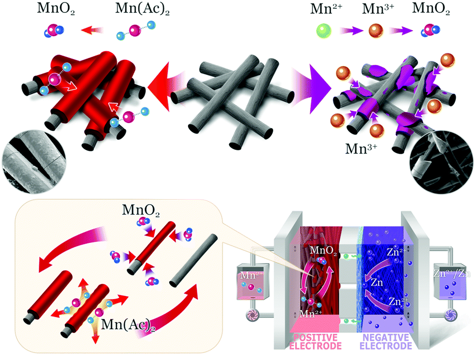 | ||
| Fig. 1 The electrochemical mechanism of the Mn(Ac)2 (top left corner) and MnSO4 electrolyte (top right corner). | ||
Results and discussion
The coordination effect of Ac− on Mn2+
Actually, the coordination effect of Ac− on the Mn2+ ion has been reported in previous work24–27 and it could be confirmed by infrared and Raman spectroscopy. From the infrared spectroscopy, a peak at about 517 cm−1, ascribed to the Mn–O band, can be found for Mn(Ac)2, while, it cannot be observed in the NaAc counterpart24 (Fig. S1, ESI†). Furthermore, Raman Spectroscopy also confirmed the existence of the Mn–O band (228 cm−1), which also proves the complex effect as well28,29 (Fig. S2, ESI†). Last but not least, an electrospray ionization mass spectrometry (EIS-MS) test also demonstrates the coordination of Mn2+ and acetate (Fig. S3, ESI†) in aqueous solution.The electrochemical principle of the redox pair
Fig. 2a displays the cyclic voltammetry curve of 0.05 M Mn(Ac)2 in 1 M KCl on a glassy carbon working electrode (d = 5 mm) at a scan rate of 10 mV s−1. A pair of well-defined peaks could be observed at a potential range of 0–1.2 V. The oxidation peak at 0.737 V (vs. SCE) was attributed to the electrochemical deposition of MnO2 from soluble Mn(Ac)2 (eqn (4)) and the corresponding reduction peak (0.428 V vs. SCE) was regarded as the dissolution of MnO2 to Mn(Ac)2.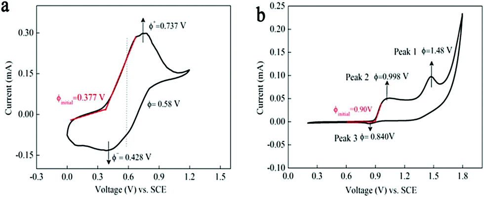 | ||
| Fig. 2 The electrochemical measurements of Mn(Ac)2 and MnSO4 on a glassy carbon working electrode. Cyclic voltammetric plot of (a) 0.05 M Mn(Ac)2 in 1 M KCl and (b) 0.05 M MnSO4 in 0.5 M K2SO4 on the glassy carbon electrode at the scan rate of 10 mV s−1. | ||
Compared with Mn(Ac)2, the MnSO4 electrolyte demonstrated two oxidation and one reduction peaks in the potential range of 0.2–1.8 V (Fig. 2b). Peak 1 at 1.48 V was possibly attributed to the oxidation of Mn2+ to Mn3+ (eqn (1)), which would disproportionate into MnO2 in aqueous solution (eqn (2)).18,19 And peak 2 with lower potential might be the deposition of MnO2 from Mn2+ (eqn (3)) and the MnO2 would be dissolved into Mn2+ at peak 3. Based on the CV plots and previous report,18 the MnO2 that reduced at peak 3 stemmed from two processes: the electrochemical deposition from Mn2+ and the disproportionation side reaction of Mn3+. However, the MnO2 stemming from the disproportionation reaction was random and uneven, and couldn’t be contacted with a conductive substrate very well or was even shed off from the electrode; hence, the reduction process suffered from a poor reversibility and kinetics (the obscure Peak 3).
It was interesting to note that the initial oxidation potential of MnO2 in the Mn(Ac)2 system was reduced by 0.53 V compared with MnSO4 (Fig. 2a and b based on the initial oxidation potential).30 And the reason should be attributed to the coordination effect of Ac− on Mn2+. When Mn(Ac)2 was charged to MnO2, it was accompanied by the formation of HAc at the same time (eqn (4)). This is because the Gibbs free energy of HAc was much lower than the free H+ such as H2SO4, therefore, less energy was required to drive this reaction, so the electrode potential of MnO2/Mn2+ decreased. Even when we swept to a much higher potential of 1.4 V, which entered into the O2 evolution region, no other redox peaks appeared (Fig. S4a, ESI†).
In order to further investigate the effect of protons on the electrochemical reaction, 0.1 M H2SO4 was added into the Mn(Ac)2 electrolyte. Obvious oxidation and reduction peaks could be observed (Fig. S4b, ESI†). Compared with Mn(Ac)2, the potential of MnO2/Mn2+ shifted positively (Peak 1). The reason is mainly due to the existence of H+ inhibiting the coordination effect of Ac− on Mn2+ (Ac− can combine with H+, which would enable it to lose the coordination ability with Mn2+); therefore, the mechanism is similar to the MnSO4 system. The upward slope after 1.5 V was the oxidation of Mn2+ to Mn3+, which merged with the oxygen evolution reaction. And the reduction peak should be attributed to the dissolution of MnO2. Due to the existence of 0.1 M H2SO4, the reduction potential was greatly enhanced (compared with Fig. 2b). Furthermore, after adding 3 M H2SO4 into the electrolyte, totally different profiles appeared (Fig. S4c, ESI†). When a large amount of H2SO4 was added, the H+ could suppress the deposition of MnO2 completely (the deposition of MnO2 was a proton generation reaction (eqn (3))). Therefore, there was just one oxidation peak, which should be ascribed to the Mn2+ to Mn3+; furthermore, because the H+ could suppress the disproportionation of Mn3+ (eqn (2)) (the disproportionation of Mn3+ was accompanied by the production of H+ and the addition of H2SO4 could inhibit the disproportionation to some extent), some of the Mn3+ could exist stably and was then reduced, when we swept to the negative side (peak 2). Nevertheless, some of the Mn3+ would still disproportionate into MnO2 and the reduction process could also be observed in peak 3. Above all, due to the large amount of H+, the reduction of MnO2 could be accelerated, which results in a much larger reduction peak.18
As for the MnSO4 system, when 0.1 M H2SO4 was added, the CV plot (Fig. S4d, ESI†) was similar to that without addition of acid (Fig. 2b). Due to the existence of extra H+, the potential of MnO2/Mn2+ was slightly improved (H+ participates in an electrochemical reaction). Above all, after adding 3 M H2SO4 (Fig. S4e, ESI†), the CV plot was similar to the Mn(Ac)2 in 3 M H2SO4 (Fig. S4c, ESI†) and so was the electrochemical mechanism. What impressed us most was that after adding 0.1 M KAc into a 0.05 M MnSO4 solution (neutral condition, without adding H2SO4), a similar plot with 0.05 M Mn(Ac)2 solution was observed, which strongly confirms the effect of Ac− on the electrochemical property of Mn2+ (Fig. S4f, ESI†).
To further confirm the electrochemical mechanism at different potentials, a visual experiment was carried out as well. It was known that the P2O74− could complex with Mn3+ to produce intense reddish violet color and, therefore, could be employed as a color indicator of Mn3+.31,32 The test was carried out by adding 0.1 M Na4P2O7 (0.25 mL) into the electrolyte (50 mL) via controlled potential coulometry at a constant potential (0.25 mL 0.1 M hydrochloric acid was used to prevent Mn2+ precipitation caused by Na4P2O7). No violet color appeared for a Mn(Ac)2 electrolyte at a potential of 0.78 V (Fig. S5a and video 1, ESI†), which means that no Mn3+ was formed during this oxidation process. The results indicated that the oxidation process of Mn(Ac)2 exactly follows eqn (4) in the voltage range of 0–1.2 V vs. SCE (Fig. 2a).
As for the MnSO4 system, no obvious violet color appeared at 1.00 V, which proved that peak 2 obeys the MnO2 deposition mechanism (eqn (3)) (Fig. S5b and Video 2, ESI†). Nevertheless, when increasing the potential to 1.5 V, violet color could be evidently observed (Fig. S5d and Video 3, ESI†), which is mainly due to the formation of Mn3+. Moreover, at a medium potential of 1.3 V, the solution appeared to be violet and then turned brown quickly (Fig. S5C and Video 4, ESI†), which also proved the existence of Mn3+.
The characterization of positive products
With high solubility, low cost and two-electron transfer properties, the Mn(Ac)2/MnO2 redox couple has great potential for a high energy density and economic energy storage device. A proof of concept was thus confirmed by assembling a flow battery with neutral Zn/Zn2+ as a negative electrode. Compared with the static battery, a flow battery can effectively inhibit the negative zinc dendrites, which enables a much stable performance. Most importantly, the flow design would also eliminate the mass transfer polarization and improve the power density. Furthermore, compared with the alkaline zinc negative electrode, the neutral counterpart would avoid the dendrite issue effectively and obtain a relatively even zinc deposition.33,34 This is mainly due to the corrosion effect of highly concentrated OH− that results in the zinc dendrites and some zinc deposition is even shed off from the substrate.A composite porous polyolefin ion conducting membrane was employed as we mentioned earlier.35 Paired with the Zn/Zn2+ (−0.76 V vs. SHE) redox couple, the formal potential for a Zn–Mn battery was about 1.58 V. The oxidation product (the electrolyte composition was 0.5 M Mn(Ac)2 + 0.5 M ZnCl2 + 2 M KCl) was further confirmed by X-ray diffraction (XRD), which demonstrated a type of δ-MnO2 (JPCDS: 00-018-0802) (Fig. S6a, ESI†)36,37 with the birnessite structure and belongs to the hexagonal crystal system. The peaks at 36, 55 and 66° correspond to (006), (301), and (119) crystal planes respectively. Moreover, the Raman scatter spectrum also demonstrates a Mn–O lattice vibration as well (Fig. S6b, ESI†).38,39 Besides, at different SOC, the XRD evaluation results are the same (Fig. S6c, ESI†). Last but not least, after discharging to a certain state, the pattern of MnO2 could be also observed with decreased crystallinity, which further confirmed the dissolution of MnO2 (Fig. S6d, ESI†).
Moreover, a thin and uniform layer (Fig. 3b and b′) could be observed on the graphite fiber very well (Fig. 3a and a′), which should be attributed to the electrochemical deposition of MnO2in situ. And for the magnified items, it could be seen that the thickness of the deposition layer can reach about 2 μm (Fig. 3b′). Most importantly, the uniform MnO2 totally vanished after discharging (Fig. 3c and c′), which further confirms the dissolution mechanism of MnO2. Furthermore, the electrochemical principle could be also confirmed via a visualization experiment in the battery. As the Na4P2O7 indicator was added into the positive electrolyte after a partial charging, no violet color was observed, indicating that there was no Mn3+ formation (Fig. S7a, ESI†). Continuously charging a battery to a higher SOC, no color variation was presented as well (Fig. S7b, ESI†), which further confirmed the deposition of MnO2 from Mn(Ac)2, rather than the oxidation of Mn2+ to Mn3+.
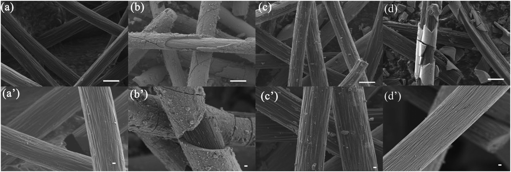 | ||
| Fig. 3 SEM images of the cathode materials at different states. (a and a′) The SEM images of the carbon fiber before the battery test (scale bar for a: 10 μm), (scale bar for a′: 1 μm). (b–b′) Morphology of MnO2 deposited on carbon fiber from Mn(Ac)2 (scale bar for b: 10 μm), (Scale bar for b′: 1 μm). (c–c′) Morphology of the carbon fiber in the Mn(Ac)2 system after discharging (scale bar for c: 10 μm), (scale bar for c′: 1 μm). (d–d′) The SEM images of the produced MnO2 from MnSO4 electrolyte (d′ exposed carbon fiber), (scale bar for d: 10 μm), (scale bar for d′: 1 μm). | ||
For comparison, a Zn–Mn flow battery with MnSO4 as an electrolyte was also evaluated. To avoid the side reaction of Cl2 evolution, sulfate was used to prepare the electrolyte (0.2 M MnSO4 + 0.5 M K2SO4 + 0.2 M ZnSO4). The XRD results indicate the formation of δ-MnO2 (Fig. S8, ESI†) (JCPDS: 00-018-0802).36,37
As we mentioned above, in a MnSO4 electrolyte, the MnO2 was mainly from disproportionation of Mn3+ (eqn (2)), which was a random and non-in situ process. Compared with the electrochemical deposition in situ of Mn(Ac)2, the MnO2 from disproportionation was loose and nonuniform, and part of them was not in good contact with the graphite fiber or was shed off the electrode (Fig. 3d and d′). Of course, this difference could also be well reflected in the charge–discharge curve of MnSO4 and Mn(Ac)2. Fig. 4a demonstrates the charge–discharge profile of a battery assembled with a 0.5 M electrolyte (0.5 M Mn(Ac)2 + 0.5 M ZnCl2 + 2 M KCl). A charging plateau of 1.8 V and a discharging plateau about 1.5 V could be clearly observed, which was consistent with the CV results in Fig. 2a. Compared with a Mn(Ac)2 electrolyte, the battery showed a single charge plateau at about 2.3 V and discharge plateau of 1.8 V (Fig. 4b). Considering the negligible polarization of a zinc anode (−0.76 V), the charge plateau of the cathode was about 1.54 V vs. SHE. The results further confirm that the charge process was mainly the oxidation of Mn2+ to Mn3+ and the discharge was the dissolution of MnO2 to Mn2+ (the MnO2 mainly stems from the disproportionation of Mn3+). Most importantly, it was possibly due to the disproportionation issues, which is a random and uneven process, that some of the MnO2 couldn’t be reduced completely. Therefore, the battery suffered from a low coulombic efficiency (CE) and voltage efficiency (VE) (Fig. 4b). (CE = 96%, VE = 74% for Mn(Ac)2; CE = 84%, VE = 64% for MnSO4).
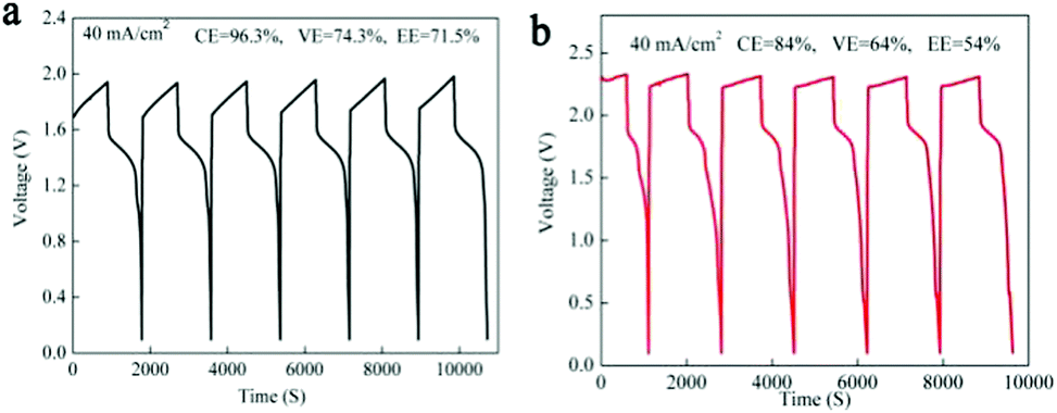 | ||
| Fig. 4 The performance of the battery assembled with Mn(Ac)2 and MnSO4. (a) The charge–discharge plot of the Zn–Mn battery in a Mn(Ac)2 system (the electrolyte composition: 0.5 M Mn(Ac)2 + 0.5 M ZnCl2 + 2 M KCl) at the current density of 40 mA cm−2. (b) The charge–discharge plot of the Zn–Mn battery in a MnSO4 system at the current density of 40 mA cm−2. The areal capacity was 10 mA h cm−2. (Electrolyte composition: 0.2 M MnSO4 + 0.2 M ZnSO4 + 0.5 M KSO4. Solubility was restricted by the common-ion effect of SO42−.) | ||
A visualization experiment was also conducted for the Zn–MnSO4 system by adding Na4P2O7 as the indicator. The appearance of violet color during charging could also confirm the existence of Mn3+ and the color deepened gradually with increased charging depth (Fig. S9, ESI†). Nevertheless, at a high areal capacity of 10 mA h cm−2, the battery suffers from a very poor cycling performance (Fig. S10a black line, ESI†), which is much worse than that of a Mn(Ac)2 based battery (Fig. S10a blue line, ESI†). However, after we reduced the areal capacity of MnSO4 by an order of magnitude to 1 mA h cm−2, the battery could continuously run for more than 800 cycles with nearly 100% coulombic efficiency (Fig. S10b, ESI†), which mainly attribute to the super thin MnO2 produced by disproportionation being able to contact with the 3D porous conductive substrate very well that could be reduced completely. However, it is impossible to achieve a higher areal capacity with a MnSO4 system.
Furthermore, due to the fact that deposition of MnO2 is accompanied by the generation of H+, it was necessary to exclude the corrosion effect of H+ on the Zn at the negative side, which would also lead to a low CE. Therefore, a zinc plate was placed on the negative side to avoid the low CE caused by complete corrosion of zinc in advance. In addition, in order to avoid the deficiency of H+ caused by the crossover issue (H+ participates in the reduction of MnO2) additional H2SO4 (H+) was added into the positive tank at the end of charge. However, the battery also suffered from a low coulombic efficiency (Fig. S11, ESI†). Therefore, the problem of coulomb efficiency decay that is caused by H+ corrosion can be eliminated.
The poor performance of MnSO4 was mainly due to the disproportionation reaction of Mn3+; therefore, it is possible to eliminate the Mn2+/Mn3+ reaction by adjusting the potential widow. A single oxidation and reduction peak can be observed after we reduced the potential range, which should be ascribed to the deposition and dissolution of MnO2 (Fig. S12a, ESI†). Furthermore, the reaction of Mn2+ to Mn3+ seem to be inhibited; therefore, a very obvious reduction peak could be achieved. Then we tested the Zn–MnSO4 battery through a constant potential control. However, the battery couldn’t be charged to a high areal capacity (only about 6 mA h cm−2), although a relatively high coulombic efficiency could be obtained (Fig. S12b, ESI†). This is mainly due to the low cut-off potential that restricts the amount of non-conductive MnO2 deposition. Nevertheless, the charging current density was normally lower than 10 mA cm−2, which indicated a low power density (Fig. S12c, ESI†). What's worse, adding the Na4P2O7 as the color indicator, light red could be clearly observed, indicating the existence of Mn3+ (Fig. S12d, ESI†). When we improved the voltage to 2.3 V, a high areal capacity could be obtained (18 mA h cm−2) (Fig. S12b, ESI†); however, the battery suffered from a very poor performance. Nevertheless, a bright red color could be observed after adding the Na4P2O7 indicator (Fig. S12d, ESI†), which indicates the existence of Mn3+ as well. Therefore, it is not easy to improve the performance of the MnSO4 based battery only by adjusting the potential range, due to the side reaction of Mn2+ to Mn3+. Therefore, the electrochemical mechanism of the Zn–Mn(Ac)2 battery could be summarized as follows:
Charge process:
Positive: 2MnAc2 + 2H2O–2e− ⇔ MnO2 + 4HAc + Mn2+
Negative: Zn2+ + 2e− ⇔ Zn
Discharge process:
Positive: MnO2 + 4HAc + Mn2+ + 2e− ⇔ 2MnAc2 + 2H2O
Negative: Zn–2e− ⇔ Zn2+
Battery performance optimization
As we mentioned above, the electrochemical mechanism of Mn(Ac)2 was the deposition of MnO2. However, compared with the traditionally deposited electrodes like Zn2+/Zn or Sn2+/Sn, MnO2 is endowed with a poor conductivity. Thus, the contact between the deposition layer and the conductive substrate would affect the electrochemical performance greatly and further determine the areal capacity. It is proved that a rougher substrate will cause a stronger bonding force between the deposition layer and the substrate. Although there are grooves on the surface of the graphite fiber (Fig. 3a, a′ and d′), the relatively smooth surface leads to a poor adhesion between the MnO2 and conductive substrate, which would not only increase the omhic polarization of the battery but also limit the areal capacity (a traditional Mn-based battery suffers from a low areal capacity).21,23 Therefore, we tried to coat carbon black on the electrode to improve the surface roughness and then the uniformity and density of MnO2 deposition. With PVDF as the binder, carbon black was coated on the graphite felt with a very low loading capacity (about 2 mg cm−2) (Fig. 5a) (Table S1, ESI†). By assembling a Zn–Mn battery with the modified positive electrode, a CE of about 99% and an energy efficiency of about 78% (Fig. 6a) could be achieved at a current density of 40 mA cm−2, which is much higher than the pristine graphite felt (Fig. 4a). Even when we replaced the negative electrode with the Cu/Cu2+ redox pair, a much higher CE could (∼98.3%) also been obtained for the Mn(Ac)2 system, which was much higher than the MnSO4 counterpart (∼84%) (Fig. S13, ESI†). Furthermore, a very compact and uniform MnO2 layer could be clearly observed on the graphite fiber (Fig. 5b–d). Compared with the voids (Fig. 3b), this deposition layer becomes very smooth and defect free. The HRTEM images indicate that the deposited MnO2 possesses a typical size of 60 nm with a layer space of 0.502 nm with a nanolayer structure (Fig. 5e and f).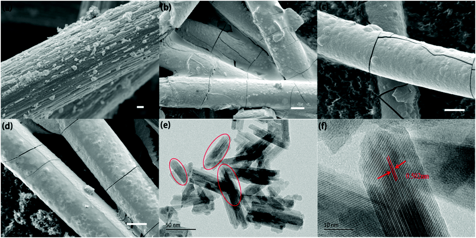 | ||
| Fig. 5 Structural and morphological characterization of the deposited MnO2 after coating carbon black. (a) The carbon fiber with the coated activated carbon (Scale bar: 1 μm). (b–d) The SEM image of carbon fibers in (a) deposited with MnO2 (scale bar: 10 μm). (e) The HRTEM image of the MnO2 nanolayers. The red profiles were employed to indicate the particle size of MnO2 (scale bar: 50 nm). (f) The nanolayer structure of the electrochemically deposited MnO2 (scale bar: 10 nm). | ||
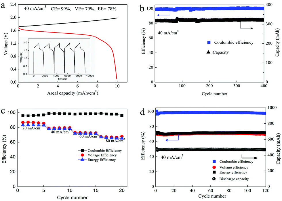 | ||
| Fig. 6 Zn–Mn flow battery performance in a 0.5 M electrolyte. (a) The charge–discharge profile of the battery at the current density of 40 mA cm−2. (b) Capacity retention and the corresponding coulombic efficiency of the battery with the areal capacity of 7 mA h cm−2. (c) The rate capability of the battery at the current range from 20 mA cm−2 to 80 mA cm−2 (10 mA h cm−2). (d) Cycling performance of the battery with the areal capability about 10 mA h cm−2 at the current density of 40 mA cm−2. | ||
Furthermore, the Zn–Mn flow battery demonstrates a very stable performance after continuously running for more than 400 cycles, showing a very good reliability (Fig. 6b). Increasing the current density from 20 mA cm−2 to 80 mA cm−2, the VE decreased from 82% to about 68% due to the improvement in the electrochemical and Ohmic polarization. And the CE remained almost 100% due to the negligible self-discharge issue (Fig. 6c). Most importantly, with a much higher loading (16 mg cm−2), the battery could also be operated for more than 120 cycles without any capacity and efficiency decay (Fig. 6d).
To further prove the reaction mechanism, we substituted the positive electrolyte with the fresh one after charging and adjust to the same pH as previously (because the formation of MnO2 was accompanied by H+ formation, the pH reduced from 6.41 to 4.02 (formation of HAc)). Then the battery was discharged at the same current density and a near 100% coulombic efficiency was obtained (Fig. S14, ESI†), which clearly confirmed that the oxidation product of the positive electrode was the depositional MnO2 instead of soluble Mn3+ in electrolyte. However, for the MnSO4 based electrolyte, an obvious coulombic efficiency decay was found after replacing the charged electrolyte with the fresh one due to the loss of Mn3+ in solution (Fig. S15, ESI†). Moreover, the disproportionated MnO2 could be clearly seen on the wall of the tank after the cycling test (Fig. S16, ESI†). It is worth mentioning that if we replace the positive electrolyte with ZnCl2 + KCl (nearly neutral condition) after charging for the Mn(Ac)2 system, a completely different discharge plot could be observed (Fig. S17, ESI†). The discharge mechanism was switched to the Zn2+ intercalating into the MnO2 nano-layer and the discharge products (ZnMn2O4) were well-evidenced by the XRD pattern (Fig. S18, ESI†).10 However, the discharge capacity was only about half the dissolution of MnO2. Therefore, the dissolution of MnO2 during the discharge process required the existence of HAc (eqn (4)). However, in the neutral environment, the electrochemical mechanism obeys the intercalation and deintercalation of Zn2+.
To further improve the energy density, a battery with a higher concentration electrolyte (1 M Mn(Ac)2 + 1 M ZnCl2 + 2 M KCl) was further investigated. A battery showed a CE of 99% and EE of 75% at a current density of 40 mA cm−2 (Fig. S19a, ESI†) and could continuously run for more than 100 cycles without any capacity decay (Fig. 7a). The decreased voltage efficiency is mainly due to the accumulation of the nonconductive MnO2 at such high areal capacity, which intensifies the Ohmic polarization (Fig. S19b, ESI†). Even when the electrolyte concentration increased to 1.5 M (1.5 M Mn(Ac)2 + 1.5 M ZnCl2 + 3 M KCl), which was near the saturation state, the battery could work smoothly with an areal capacity of 20 mA h cm−2 (Fig. 7b), which is the highest value ever reported.21,23 Furthermore, the energy density could reach about 26 W h L−1 with the theoretical value of about 56 W h L−1.
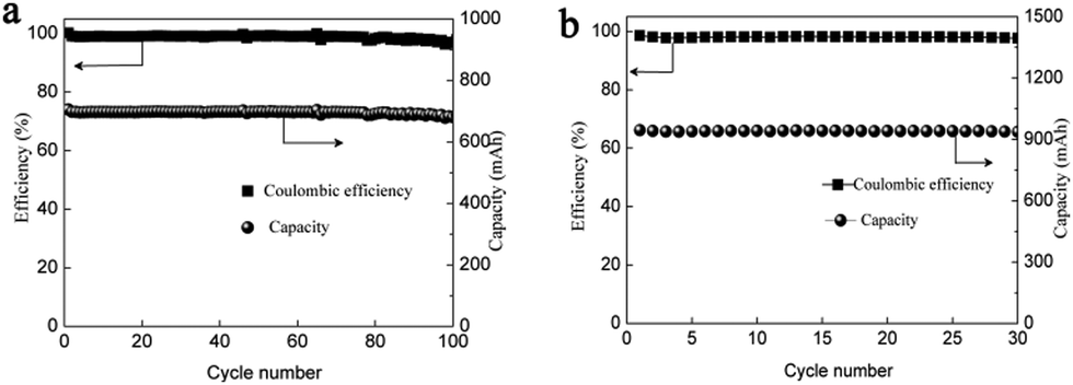 | ||
| Fig. 7 The performance of the battery assembled with 1 M and 1.5 M electrolyte. The cycling performance (a) of the battery at the current density of 40 mA cm−2. The cycling performance (b) of the battery assembled with a 1.5 M electrolyte. | ||
Electrolyte composition optimization
As described above, the H+ has a great effect on the charging mechanism of a Zn–Mn battery, since it could complex with Ac− and diminish the coordination effect of Ac− on Mn2+. For a typical electrolyte, the ratio of Mn2+ to Ac− initially maintained at 1![[thin space (1/6-em)]](https://www.rsc.org/images/entities/char_2009.gif) :2. However, during the conversion of Mn2+ into MnO2, it was accompanied by the generation of H+, which was two-fold of the Ac− (eqn (4)). Therefore, when 50% of the Mn2+ was consumed (50% of the Mn2+ was charged into MnO2), there was no residual Ac− in the electrolyte. After charging the battery to a much higher SOC, another charging plateau could be observed at high potential, which should be ascribed to the oxidation of Mn2+ to Mn3+ (Fig. S19c, ESI†). It was due to the fact that the formation of H+ was accompanied during the deposition of MnO2. The H+ could combine with Ac− and break the coordination effect on Mn2+. Therefore, only when the Ac− combined with H+ completely, the Mn2+/Mn3+ redox pair would occur and the potential of Mn2+/Mn3+ in Mn(Ac)2 was similar to that of MnSO4.
:2. However, during the conversion of Mn2+ into MnO2, it was accompanied by the generation of H+, which was two-fold of the Ac− (eqn (4)). Therefore, when 50% of the Mn2+ was consumed (50% of the Mn2+ was charged into MnO2), there was no residual Ac− in the electrolyte. After charging the battery to a much higher SOC, another charging plateau could be observed at high potential, which should be ascribed to the oxidation of Mn2+ to Mn3+ (Fig. S19c, ESI†). It was due to the fact that the formation of H+ was accompanied during the deposition of MnO2. The H+ could combine with Ac− and break the coordination effect on Mn2+. Therefore, only when the Ac− combined with H+ completely, the Mn2+/Mn3+ redox pair would occur and the potential of Mn2+/Mn3+ in Mn(Ac)2 was similar to that of MnSO4.
Thus, to improve the utilization of the electrolyte, we optimized the electrolyte composition to Zn(Ac)2 + Mn(Ac)2+ KCl, which means the proportion of Ac− is 4 times that of Mn2+. By using 0.5 M Mn(Ac)2 + 0.5 M Zn(Ac)2 + 2 M KCl as an example, the areal capacity could reach about 13.3 mA h cm−2 (Fig. 8a), which was 1.4 times higher than the electrolyte of 0.5 M Mn(Ac)2+ 0.5 M ZnCl2 + 2 M KCl (Fig. 6a). Therefore, the coordination effect of Ac− on the electrochemistry could be further confirmed. With the areal capability of 13.3 mA h cm−2, the battery could continuously run for more than 100 cycles (Fig. 8b). Further improving the flowing rate from 50 mL min−1 to 70 mL min−1, a much higher electrolyte utilization could be achieved, furthermore, the battery could be operated for more than 100 cycles (Fig. 8c) with the energy density of about 24 W h L−1. There was no change of the charge–discharge plot during cycling (the areal capacity was about 10 mA h cm−2) (Fig. S19d, ESI†). However, for the MnSO4 with a much lower areal capacity (about 1 mA h cm−2) (the battery could only operate stably at low areal capacity), there was an obvious change for the charge–discharge curve (Fig. S20a, ESI†). The discharge plateau at high voltage disappeared, and a huge slope becomes more and more obvious. We assume it is the accumulation of MnO2 that leads to an intercalation of Zn2+ (Fig. S20b, ESI†).
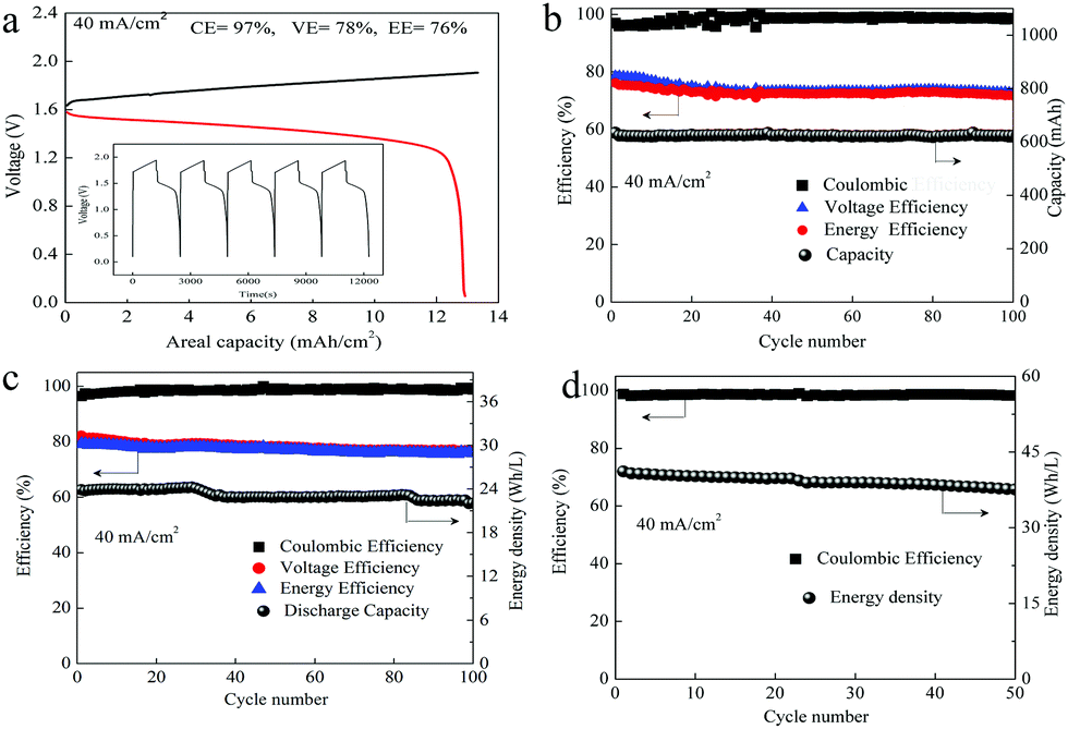 | ||
| Fig. 8 The performance of the battery assembled with the optimized electrolyte. (a) Charge–discharge plot of the flow battery with 0.5 M Mn(Ac)2 + 0.5 M Zn(Ac)2 + 2 M KCl. (b) The cycling performance of “a” at the current density of 40 mA cm−2. (c) The cycling performance of the flow battery assembled with a peristaltic pump with 0.5 M Mn(Ac)2 + 0.5 M Zn(Ac)2 + 2 M KCl and 1 M Mn(Ac)2 + 1 M Zn(Ac)2 + 2 M KCl (d). | ||
Even with a much higher concentration of electrolyte (1 M Mn(Ac)2 + 1 M Zn(Ac)2 + 2 M KCl), a decent performance with the energy density of 42 W h L−1 (CE of 99% and EE of 75% at a current density of 40 mA cm−2) could be obtained as well (Fig. 8d), showing very promising performance. The solubility of the optimized electrolyte could reach about 1 M which means a theoretical energy density of about 75 W h L−1 (based on the discharge plateau of ∼1.4 V).
Compared with the previously reported zinc ion batteries and Mn based batteries, the reported system has obvious advantageous in terms of the power density and specific capacity. (Fig. 9). (All the references and calculation methods are supplied in the ESI†).
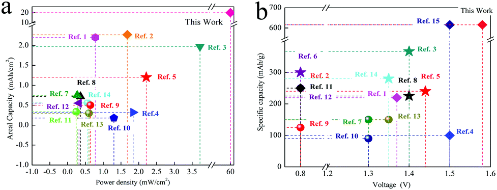 | ||
| Fig. 9 The comparison of different Zinc ion batteries. (a) The power density and areal capacity. (b) The voltage and specific capacity. | ||
Static rechargeable Zn/MnO2 battery under neutral medium
Zinc–manganese primary batteries under an alkaline medium have dominated the battery market for several decades. However, the poor stability of the positive electrode and the zinc dendrites are always the critical issues that prevent them becoming rechargeable. Here, the realization of a direct transition from Mn2+ to MnO2 affords a Zn–Mn battery with high cycling stability and makes the rechargeable Zn–Mn battery more practical. In addition, the neutral system can effectively avoid zinc dendrites as well. Therefore, a Zn–Mn static battery was assembled by removing the pump and pipeline from the positive and negative sides of the flow battery. With the optimized electrolyte of 1 M Mn(Ac)2 + 1 M Zn(Ac)2 + 2 M KCl, the battery could achieve a CE of 97% and EE of 73% at a current density of 20 mA cm−2 (Fig. 10), showing very promising prospects for large scale energy storage.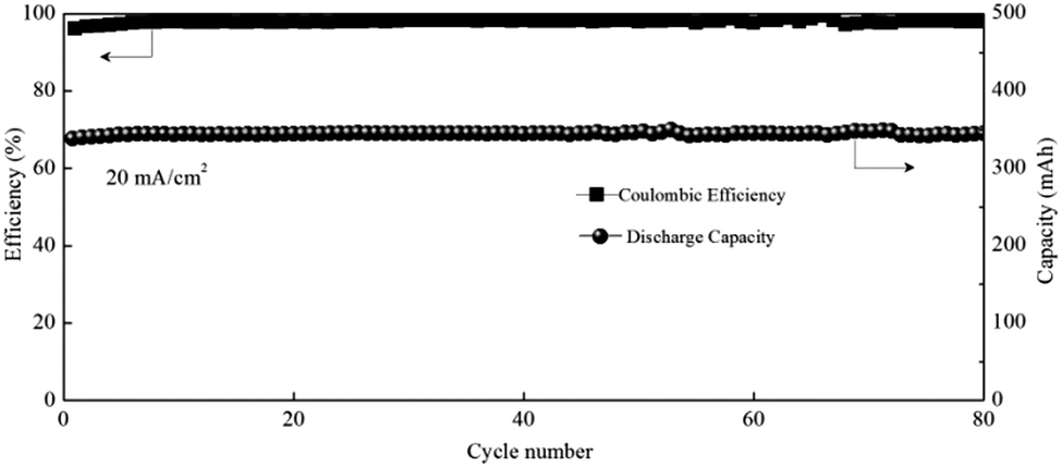 | ||
| Fig. 10 The performance of the Zn–Mn static battery. | ||
Conclusions
In summary, a reversible Mn2+/MnO2 redox couple with high stability was presented for the first time. Benefiting from the coordination ability of Ac−, the Mn2+ could be charged to MnO2 directly, which is completely different from the MnSO4, where the reaction is accompanied by the disproportionation of Mn3+. Compared with the intercalation based zinc ion battery, which suffers from intrinsic phase transition issues, this redox pair has enormous potential for achieving a battery with higher stability and capacity. Most importantly, a proof of concept could be realized by pairing with the Zn/Zn2+ redox pair to form a Zn–Mn flow battery. And the battery could achieve an energy efficiency of 78% at a current density of 40 mA cm−2, which is the highest one among the reported Mn-based rechargeable batteries. Furthermore, the battery can continuously run for more than 400 cycles without capacity and efficiency decay, demonstrating a very high stability. Last but not least, the testing electrolyte of Mn2+ could reach the saturation state (1.5 M) and a high areal capacity of about 20 mA h cm−2 can be achieved, which is an order of magnitude higher than previous reports. With the high stability, electrochemical reversibility, low cost and two-electron transfer property, the solid–liquid Mn/MnO2 couple can be a promising candidate for electrochemical energy storage devices.Conflicts of interest
The authors declare no competing financial interests.Acknowledgements
The authors sincerely acknowledge the funding support from Natural Science Foundation of China (No. 21925804, 21935003), the CAS-STS program, CAS-DOE collaborative Project (121421KYSB20170032) and DICP funding (ZZBS201707) and Liaoning Revitalization Talents Program (XLYC1802050).Notes and references
- F. Mo, G. Liang, Q. Meng, Z. Liu, H. Li, J. Fan and C. Zhi, Energy Environ. Sci., 2019, 12, 706–715 RSC.
- F. Y. Cheng, J. Chen, X. L. Gou and P. W. Shen, Adv. Mater., 2005, 17, 2753–2756 CrossRef CAS.
- K. W. Nam, H. Kim, J. H. Choi and J. W. Choi, Energy Environ. Sci., 2019, 12, 1999–2009 RSC.
- I. Manke, J. Banhart, A. Haibel, A. Rack, S. Zabler, N. Kardjilov, A. Hilger, A. Melzer and H. Riesemeier, Appl. Phys. Lett., 2007, 90, 214102 CrossRef.
- N. D. Ingale, J. W. Gallaway, M. Nyce, A. Couzis and S. Banerjee, J. Power Sources, 2015, 276, 7–18 CrossRef CAS.
- W. Wruck, B. Reichman, K. Bullock and W. H. Kao, J. Electrochem. Soc., 1991, 138, 3560–3567 CrossRef CAS.
- A. M. Kannan, S. Bhavaraju, F. Prado, M. M. Raja and A. Manthiram, J. Electrochem. Soc., 2002, 149, A483–A492 CrossRef CAS.
- B. Lee, H. R. Lee, H. Kim, K. Y. Chung, B. W. Cho and S. H. Oh, Chem. Commun., 2015, 51, 9265–9268 RSC.
- B. Lee, C. S. Yoon, H. R. Lee, K. Y. Chung, B. W. Cho and S. H. Oh, Sci. Rep., 2014, 4, 6066 CrossRef CAS PubMed.
- C. Xu, B. Li, H. Du and F. Kang, Angew. Chem., 2012, 51, 933–935 CrossRef CAS PubMed.
- J. Huang, Z. Wang, M. Hou, X. Dong, Y. Liu, Y. Wang and Y. Xia, Nat. Commun., 2018, 9, 2906 CrossRef PubMed.
- N. Zhang, F. Cheng, J. Liu, L. Wang, X. Long, X. Liu, F. Li and J. Chen, Nat. Commun., 2017, 8, 405 CrossRef PubMed.
- H. Pan, Y. Shao, P. Yan, Y. Cheng, K. S. Han, Z. Nie, C. Wang, J. Yang, X. Li, P. Bhattacharya, K. T. Mueller and J. Liu, Nat. Energy, 2016, 1, 16039 CrossRef CAS.
- N. R. Jens Noack, T. Herr and P. Fischer, Angew. Chem., Int. Ed., 2014, 54, 9776–9809 CrossRef PubMed.
- K. Gong, Q. Fang, S. Gu, S. F. Y. Li and Y. Yan, Energy Environ. Sci., 2015, 8, 3515–3530 RSC.
- M. Skyllas-Kazacos, M. H. Chakrabarti, S. A. Hajimolana, F. S. Mjalli and M. Saleem, J. Electrochem. Soc., 2011, 158, R55–R79 CrossRef CAS.
- Z. He, G. Jin, C. Gao, Y. Chen, H. Han and J. Liu, J. Renewable Sustainable Energy, 2014, 6, 053124 CrossRef.
- F.-Q. Xue, Y.-L. Wang, W.-H. Wang and X.-D. Wang, Electrochim. Acta, 2008, 53, 6636–6642 CrossRef CAS.
- Y.-R. Dong, H. Kaku, K. Hanafusa, K. Moriuchi and T. Shigematsu, ECS Trans., 2015, 69, 59–67 CrossRef CAS.
- J. Rubio-Garcia, A. Kucernak, D. Zhao, D. Li, K. Fahy, V. Yufit, N. Brandon and M. Gomez-Gonzalez, J. Phys. Energy, 2018, 1, 015006 CrossRef.
- W. Chen, G. Li, A. Pei, Y. Li, L. Liao, H. Wang, J. Wan, Z. Liang, G. Chen, H. Zhang, J. Wang and Y. Cui, Nat. Energy, 2018, 3, 428–435 CrossRef CAS.
- S. Rodrigues, A. Shukla and N. Munichandraiah, J. Appl. Electrochem., 1998, 28, 1235–1241 CrossRef CAS.
- D. Chao, W. Zhou, C. Ye, Q. Zhang, Y. Chen, L. Gu, K. Davey and S. Z. Qiao, Angew. Chem., Int. Ed., 2019, 58, 7823–7828 CrossRef CAS PubMed.
- R. Krishnan and S. Vancheesan, J. Mol. Catal. A: Chem., 1999, 142, 377–382 CrossRef CAS.
- H.-J. Yang, H.-Z. Kou, Z.-H. Ni, A.-L. Cui and R.-J. Wang, Inorg. Chem. Commun., 2005, 8, 846–849 CrossRef CAS.
- A. B. Sushkov, B. R. Jones, J. L. Musfeldt, Y. J. Wang, R. M. Achey and N. S. Dalal, Phys. Rev. B: Condens. Matter Mater. Phys., 2001, 63, 214408 CrossRef.
- M. Devereux, M. McCann, V. Leon, V. McKee and R. J. Ball, Polyhedron, 2002, 21, 1063–1071 CrossRef CAS.
- J. M. North, R. M. Achey and N. S. Dalal, Phys. Rev. B: Condens. Matter Mater. Phys., 2002, 66, 174437 CrossRef.
- J. M. North, L. J. van de Burgt and N. S. Dalal, Solid State Commun., 2002, 123, 75–79 CrossRef CAS.
- J. N. Broughton and M. J. Brett, Electrochim. Acta, 2005, 50, 4814–4819 CrossRef CAS.
- J. J. Lingane and R. Karplus, Ind. Eng. Chem., Anal. Ed., 1946, 18, 191–194 CrossRef CAS.
- J. I. Watters and I. M. Kolthoff, J. Am. Chem. Soc., 1948, 70, 2455–2460 CrossRef CAS.
- Z. Yuan, Y. Yin, C. Xie, H. Zhang, Y. Yao and X. Li, Adv. Mater., 2019, 1902025 CrossRef CAS PubMed.
- W. Lu, C. Xie, H. Zhang and X. Li, ChemSusChem, 2018, 11, 3996–4006 CrossRef CAS PubMed.
- C. Xie, Y. Liu, W. Lu, H. Zhang and X. Li, Energy Environ. Sci., 2019, 12, 1834–1839 RSC.
- M. M. Najafpour, S. Madadkhani, T. Tomo and S. I. Allakhverdiev, New J. Chem., 2017, 41, 10627–10633 RSC.
- Y. Jiang, X. Feng, G. Cheng, Y. Li, C. Li, Z. He, J. Zhu, W. Meng, H. Zhou and L. Dai, Electrochim. Acta, 2019, 322, 134754 CrossRef CAS.
- T. Gao, M. Glerup, F. Krumeich, R. Nesper, H. Fjellvåg and P. Norby, J. Phys. Chem. C, 2008, 112, 13134–13140 CrossRef CAS.
- W.-H. Ryu, D.-W. Han, W.-K. Kim and H.-S. Kwon, J. Nanopart. Res., 2011, 13, 4777–4784 CrossRef CAS.
Footnote |
| † Electronic supplementary information (ESI) available. See DOI: 10.1039/c9ee03702k |
| This journal is © The Royal Society of Chemistry 2020 |