
Entropymetry for non-destructive structural analysis of LiCoO2 cathodes†
Hye Jin
Kim‡
a,
Youngkyu
Park‡
a,
Yoonjin
Kwon
a,
Jaeho
Shin
a,
Young-Han
Kim
b,
Hyun-Seok
Ahn
b,
Rachid
Yazami
c and
Jang Wook
Choi
 *a
*a
aSchool of Chemical and Biological Engineering and Institute of Chemical Processes, Seoul National University, 1 Gwanak-ro, Gwanak-gu, Seoul 08826, Republic of Korea. E-mail: jangwookchoi@snu.ac.kr
bKorea Electronics Technology Institute (KETI), 11 World Cup buk-ro 54-gil, Mapo-gu, Seoul 03924, Republic of Korea
cKVI PTE LTD, 2 Cleantech Loop, Singapore 637144
First published on 4th December 2019
Abstract
Upon the emergence of electric vehicles, accurate and non-destructive monitoring of battery electrode materials during operation is highly desirable. Structural degradation of widely adopted intercalation-based materials constitutes the origin of their capacity fading and safety deterioration. Here, we introduce entropymetry to monitor the structural changes of LiCoO2 (LCO) and its nickel (Ni)-doped derivatives at different states of charge (SOC). While simple lithium (Li) extraction on charging gives a monotonic decline of entropy change (ΔS) based on progressive vacancy occupation over Li sites, the presence of a monoclinic intermediate phase inverses the slope of the ΔS profile to reflect its limited atomic configurations with high ordering. Furthermore, Ni-doping lessens the ordering of the monoclinic phase, decreasing the height amplitude of ΔS profile in the monoclinic regime. The increased disorder by Ni-doping enhances the stability of the lattice framework, extending the cycle life with high voltage cut-off (4.6 V vs. Li/Li+). The present study highlights entropymetry as a unique, non-destructive tool in monitoring the structural ordering and relevant degradation of electrode materials in lithium-ion batteries.
Broader contextThe required cycle life of rechargeable batteries for electric vehicles (i.e., 80% capacity retention for 10 years over 100![[thin space (1/6-em)]](https://www.rsc.org/images/entities/char_2009.gif) 000 miles) is a daunting challenge, even for state-of-the-art battery systems. While champion materials and optimized cell conditions are essential for this purpose, intelligent cell operation is equally important in extending cell lifespan. Although battery management systems serve such a role, their functions are usually based on current, voltage, and temperature, without taking the chemical state of electrode materials into account. In this sense, the current study suggests entropymetry as a useful diagnostic tool in monitoring the state of electrode materials in a non-destructive fashion. The lattice configuration alteration involving Li and transition metal changes the entropy of the material, offering useful structural information of LiCoO2, a model material of interest in this study. With the same logic, acquisition of entropy change can capture the lattice ordering change of an intermediate phase, such as the monoclinic phase in LiCoO2. Different amounts of Ni-doping to LiCoO2 were detected by the entropy change in the monoclinic intermediate phase and correlated with improved cycle life via a stabilized oxygen framework bearing lithium–nickel cation exchange. Hence, entropy change can serve as a key parameter for non-destructive diagnosis of the state and evolution of a battery electrode material, which can provide useful input for an intelligent operation algorithm. 000 miles) is a daunting challenge, even for state-of-the-art battery systems. While champion materials and optimized cell conditions are essential for this purpose, intelligent cell operation is equally important in extending cell lifespan. Although battery management systems serve such a role, their functions are usually based on current, voltage, and temperature, without taking the chemical state of electrode materials into account. In this sense, the current study suggests entropymetry as a useful diagnostic tool in monitoring the state of electrode materials in a non-destructive fashion. The lattice configuration alteration involving Li and transition metal changes the entropy of the material, offering useful structural information of LiCoO2, a model material of interest in this study. With the same logic, acquisition of entropy change can capture the lattice ordering change of an intermediate phase, such as the monoclinic phase in LiCoO2. Different amounts of Ni-doping to LiCoO2 were detected by the entropy change in the monoclinic intermediate phase and correlated with improved cycle life via a stabilized oxygen framework bearing lithium–nickel cation exchange. Hence, entropy change can serve as a key parameter for non-destructive diagnosis of the state and evolution of a battery electrode material, which can provide useful input for an intelligent operation algorithm.
|
Introduction
With the emergence of electric vehicles (EVs) and energy storage systems (ESSs), ever-challenging standards are imposed on rechargeable batteries with respect to their lifespan and safety.1–3 Charge–discharge cycling of lithium-ion batteries (LIBs) generally causes structural and interfacial changes in the active materials, which result in capacity fading involving a variety of failure modes such as particle fracture and solid–electrolyte-interphase (SEI) destabilization.4,5 Thus, besides identifying advanced electrode components with high performance, it is highly desirable to monitor the structural evolutions of electrode materials at a given state of cell operation.Many analytical tools based on various microscopes,6–9 spectrometers,10–14 and diffractometers15–17 are currently used to characterize the crystal structures and atomic bond characters of battery electrode materials. However, most of these analyses require cell disassembly, along with high-cost equipment, and are thus ‘destructive.’ Not only is it a tedious task to recover the cell components for post-mortem analysis, but it also renders the cell useless, which is undoubtedly cost-ineffective. Therefore, a simple yet non-destructive analytic method by which the states of battery materials can accurately be diagnosed during operation would certainly save time and cost.
In this respect, entropy is a valuable parameter for gauging the current health status of a battery. Entropy is a state function related to the degree of disorder or randomness of a system. From a statistical mechanics viewpoint, entropy refers to the number of arrangements of atoms in a system of atomic array. In particular, for LIB electrode materials where Li+ ions are reversibly (de)intercalated (from)into the host structure during cycling, entropy is associated with the number of possible lattice configurations in which Li atoms are arranged with other lattice atoms.18,19 According to the Boltzmann definition of entropy (S),
| S = kB·lnW | (1) |
As the crystal structure continuously changes and degrades over cycling, the entropy profiles would also change. Therefore, entropy change (ΔS) measurements, so-called entropymetry, can provide valuable information about structural transformations of electrode materials.
ΔS can be measured based on the following rationale. Assuming a quasi-equilibrium state where an infinitesimal amount of Li+ (Δx) is extracted from the cathode, the change of Gibbs free energy (ΔG) is equal to the electrical work (We) done at the open-circuit voltage (OCV):
| ΔG = ΔxFE = We | (2) |
Dividing both sides by Δx and approximating it to zero,
 | (3) |
From Maxwell relations at the isobaric condition,
| dG = VdP − SdT = −SdT | (4) |
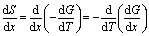 | (5) |
Combination of the eqn (3) and (5) results in:
 | (6) |
Therefore, ΔS of electrode materials can be assessed by measuring OCV change over varying temperatures.
There have been some attempts to measure ΔS of a battery cell,20–27 but an in-depth correlation of ΔS to structural changes was not provided. In fact, to date, entropymetry has not been seriously considered as a reliable diagnosis tool for battery electrode materials during cell operation. In the present work, we demonstrate entropymetry as a non-destructive analytical technique to monitor the structural changes of LiCoO2 (LCO) and nickel (Ni)-doped LCO during their battery cycling. Although diverse layered metal oxide analogues are adopted or under consideration as cathode materials for commercial lithium-ion batteries, LCO is still the most widely adopted, especially for mobile IT devices due to extensive knowledge of the correlation between its structural properties and long-term cyclability, along with a well-established manufacturing process. However, LCO suffers from unwanted phase transitions and structure destabilization upon exposure to high voltage operations (i.e., >4.5 V vs. Li/Li+).28,29 In order to enhance the structural stability of LCO at high voltage, several studies were carried out to replace cobalt (Co) with other metals such as Al, Ni, Mg, etc.30–34 Benchmarking those approaches, we synthesized LCO and Ni-doped LCO via a sol–gel process and investigated the effect of Ni-doping on structural stability over cycling. More importantly, we identified the structural evolutions of those materials by following ΔS and demonstrated entropymetry as a useful, non-destructive tool in analyzing battery electrode materials during cell operation.
Results and discussion
Synthesis of LCO and Ni-doped LCO
LCO and Ni-doped LCO cathode materials were prepared by a sol–gel process, as illustrated in Fig. 1a. Three samples with different Co-to-Ni stoichiometric ratios of 100:0, 97:3, and 95:5 were synthesized. Hereafter, we denote these bare LCO and Ni-doped LCO as Co100, Co97, and Co95, respectively, for convenience. The resulting powders were analyzed using inductively coupled plasma (ICP), scanning electron microscopy (SEM) and X-ray diffraction (XRD). ICP analysis verified that synthesized samples have the intended Co-to-Ni ratios (Table S1, ESI†). Fig. 1b shows the SEM images of Co100, Co97, and Co95. Regardless of the Ni content, all samples exhibited polygonal particle shapes with an average size near 2.0 μm. The XRD patterns of the three samples reveal that they are iso-structural with layered α-NaFeO2 under space group R![[3 with combining macron]](https://www.rsc.org/images/entities/char_0033_0304.gif) m (Fig. 1c). The evident peak splitting of (006)/(102) and (108)/(110) indicates their layered structures in which Li and transition metal atoms constitute alternating layers consisting of the oxygen octahedra framework. In addition, as the Ni content increases, the (003) peak shifts to lower 2-theta values, implying the expansion of the lattice framework along the c-axis because of the larger cation size of Ni3+ than Co3+ (Fig. 1d). However, as shown in Fig. 1e, the specific capacities of all the three samples are approximately 142 mA h g−1. Therefore, the electrochemical capacity is not significantly affected by the amount of Ni in this doping range.
m (Fig. 1c). The evident peak splitting of (006)/(102) and (108)/(110) indicates their layered structures in which Li and transition metal atoms constitute alternating layers consisting of the oxygen octahedra framework. In addition, as the Ni content increases, the (003) peak shifts to lower 2-theta values, implying the expansion of the lattice framework along the c-axis because of the larger cation size of Ni3+ than Co3+ (Fig. 1d). However, as shown in Fig. 1e, the specific capacities of all the three samples are approximately 142 mA h g−1. Therefore, the electrochemical capacity is not significantly affected by the amount of Ni in this doping range.
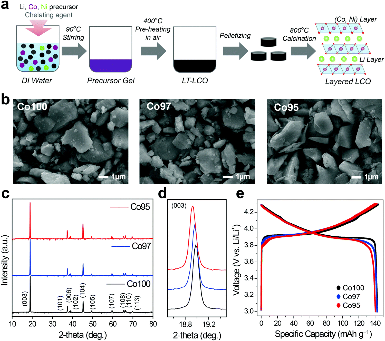 | ||
| Fig. 1 (a) Schematic illustration of sol–gel synthesis for Co100, Co97, and Co95 cathode materials. (b) SEM images of Co100, Co97, and Co95. (c) XRD patterns of Co100, Co97 and Co95 and (d) their magnified view of (003) peaks. (e) Charge–discharge curves of Co100, Co97, and Co95 during pre-cycles in the potential range of 3.0–4.3 V when measured at a current density of 10 mA g−1. | ||
Interpretation of ΔS profiles
Before measuring ΔS of Co100, Co97, and Co95, it is instructive to see how to interpret ΔS profiles in correlation with the atomic arrangement. Fig. 2a and b display a schematic example of a 2 × 2 atomic lattice, its entropy, and ΔS landscapes with respect to extracted Li content. If all Li+ sites are energetically identical and no interaction between Li+ exists (ideal case), the number of microstates is 1 in both empty and fully-filled lattices (Fig. 2a). When the number of extracted Li+ is 1, 2, and 3, the number of possible configurations is 4 (![[double bond, length as m-dash]](https://www.rsc.org/images/entities/char_e001.gif) 4C1), 6 (4C2), and 4 (4C3), respectively. According to eqn (1), the entropy of both endpoints is 0, and it has a maximum value when Li+ atoms occupy half of the available sites. The resulting entropy profile is a volcano-type plot, and its derivative profile has a slanted S-shape. In reality, however, certain Li-vacancy arrangements are preferred due to repulsive forces between Li+ in the lattice (Fig. 2b). When the difference between the amount of Li+ and vacancy is significant (i.e., high and low Li+ concentration), the entropy may follow the ideal case to a certain extent. However, near half Li+ occupation, a consecutive Li–Li arrangement is unlikely due to Li+–Li+ repulsion. Thus, the number of microstates drops drastically to 2, resulting in an entropy profile in the shape of a two-humped camel. The ΔS at this point rises sharply, crossing zero at the local minimum of the entropy profile. Therefore, the presence of Li-vacancy ordering can be detected through an abrupt increase in the ΔS profile.
4C1), 6 (4C2), and 4 (4C3), respectively. According to eqn (1), the entropy of both endpoints is 0, and it has a maximum value when Li+ atoms occupy half of the available sites. The resulting entropy profile is a volcano-type plot, and its derivative profile has a slanted S-shape. In reality, however, certain Li-vacancy arrangements are preferred due to repulsive forces between Li+ in the lattice (Fig. 2b). When the difference between the amount of Li+ and vacancy is significant (i.e., high and low Li+ concentration), the entropy may follow the ideal case to a certain extent. However, near half Li+ occupation, a consecutive Li–Li arrangement is unlikely due to Li+–Li+ repulsion. Thus, the number of microstates drops drastically to 2, resulting in an entropy profile in the shape of a two-humped camel. The ΔS at this point rises sharply, crossing zero at the local minimum of the entropy profile. Therefore, the presence of Li-vacancy ordering can be detected through an abrupt increase in the ΔS profile.
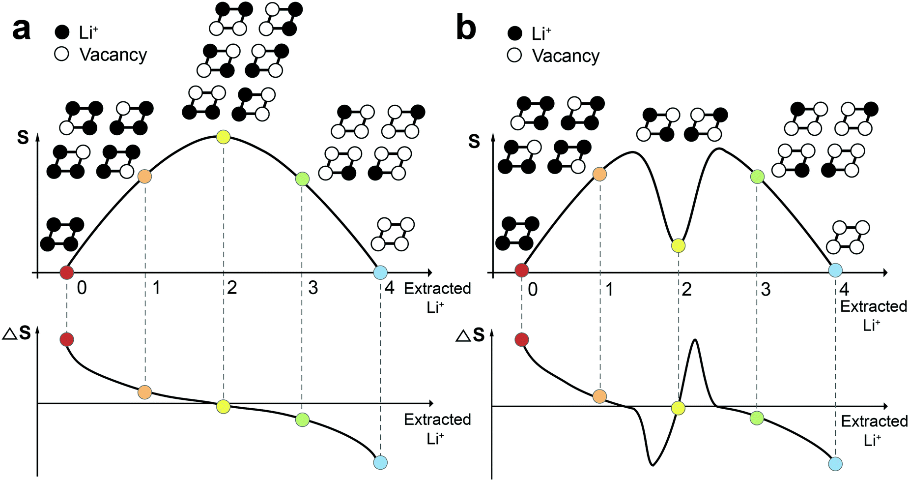 | ||
| Fig. 2 Comparison of entropy and ΔS profiles in the cases (a) without and (b) with the interaction between Li+ ions. | ||
Entropy measurement of pristine LCO
To measure the ΔS of Co100, Co97, and Co95, coin half-cells were fabricated. Each cell was pre-cycled for two cycles to stabilize the interface of the electrode. Following eqn (6), all ΔS profiles were plotted by subtracting the constant ΔS of Li metal (29.1 J mol−1 K−1)35 from the measured ΔS to focus on the cathode. Due to its simplicity, the ΔS of Co100 was first measured as shown in Fig. 3. We divided the ΔS profile when it deviates from the ideal case which monotonically decreases with increasing the x value in Li1−xCoO2. Based on this criterion, a region with a flat plateau and a region with slope reversal, respectively, were extracted, and each region could be interpreted based on the Li-vacancy ordering associated with the phase changes.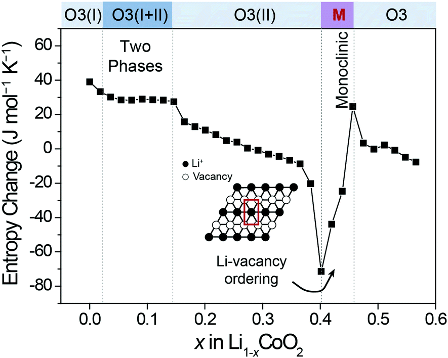 | ||
| Fig. 3 ΔS profile of Li1−xCoO2 as a function of Li+ content. | ||
The original structure of fully-lithiated LCO retains the hexagonal phase with O3 stacking, which is denoted as O3(I). As Li+ de-intercalates, the repulsive force between O2− in the framework increases, resulting in a gradual lattice expansion along the c-axis and a phase transition from O3(I) to O3(II).36,37 The newly formed O3(II) phase has the same hexagonal crystal structure as the original O3(I) with a larger c-axis lattice constant. The flat ΔS plateau is attributed to the co-existence of the two phases (O3(I) + O3(II)) forming phase boundaries. According to the Gibbs phase rule, when two phases are present in a binary component system (Li and the host) at constant total pressure and temperature, an additional degree of freedom is unavailable. This equally represents an independent ΔS from the Li composition, resulting in a flat ΔS profile with respect to composition change.
Another region of interest (0.4 < x < 0.46) is where ΔS increases sharply, which appears to be associated with Li-vacancy ordering as described above. Previous theoretical and electron diffraction studies also explained this Li-vacancy ordering phenomenon based on Li+–Li+ repulsion.38–40 Such Li-vacancy ordering leads to distortion of the layered structure, giving rise to monoclinic symmetry. The decreasing slopes of the ΔS profile in other regions can be explained by gradual reduction of Li content as described in Fig. 2a. In this way, the ΔS profile in each region is well correlated with the atomic configuration and the structural changes, and the ΔS profile follows the same trend with the voltage profile in terms of slope variation (Fig. S1, ESI†).41,42 Furthermore, the entropy change profiles of LCO were reproducible with multiple cells (Fig. S2, ESI†) and were also consistent with those in the literature.18
Effect of nickel doping
Fig. 4 depicts the effect of Ni-doping on the ionic configuration in the crystal structure of LCO. During Li+ extraction, Co3+ holds its original sites distinguished from those of Li+ (Fig. 4a), while Ni2+ tends to migrate to a Li+ vacancy due to their similar ionic radii (0.69 Å and 0.76 Å, respectively) (Fig. 4b). This well-known phenomenon is called cation-mixing,34,43 which occurs during synthesis and usually amplifies with cycling. For the monoclinic phase where Li+ atoms are arranged in a highly ordered fashion, even a small quantity of Ni2+ migration to the Li+ sites and their permanent positioning at those sites can effectively obstruct the ordering.44 Therefore, the ΔS profile can grasp cation-mixing via alteration in the ordering of Li+ configuration.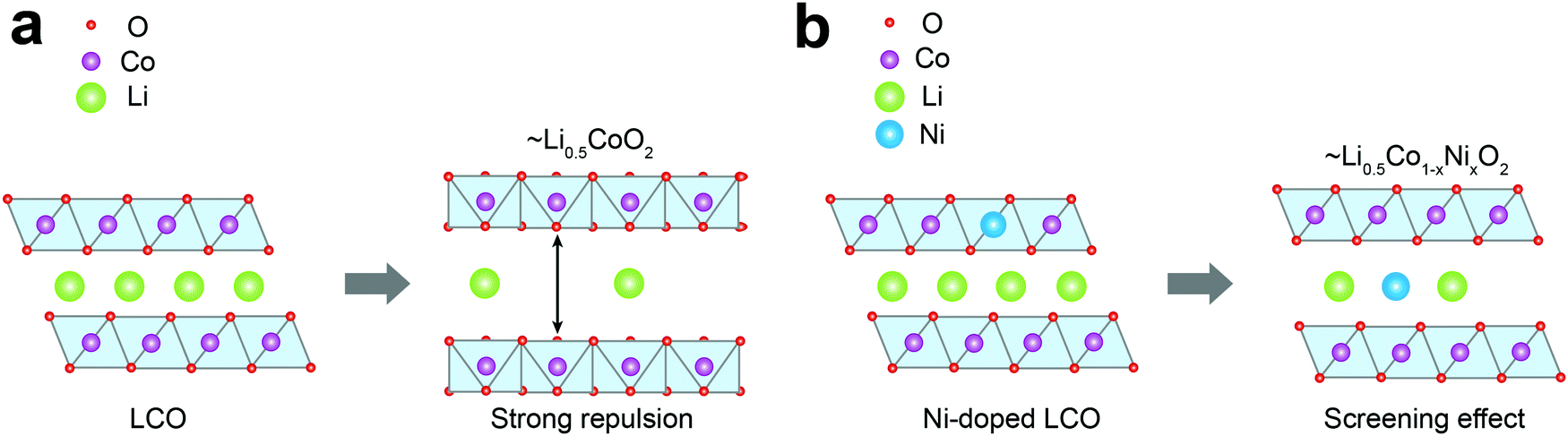 | ||
| Fig. 4 Schematic diagrams of phase transition during Li+ extraction from (a) LCO and (b) Ni-doped LCO. | ||
In situ XRD analysis was performed to examine the effect of cation mixing on the crystal structure. Fig. 5a shows the integrated intensity ratios of I(003)/I(104) for each sample at the pristine state. This intensity ratio reflects the degree of the cation mixing, and decreases from 1.77 to 1.46 as the Ni content increases from 0 at% to 5 at%. After pre-cycling, in situ XRD analysis was carried out while the three electrodes were charged. As displayed in Fig. 5b, the charging profiles of those electrodes are quite similar with almost the same specific capacities regardless of Ni content. In Fig. 5c–e, the progressive XRD profiles reveal that the (003) peaks of the three electrodes are similarly shifted to the left and then to the right throughout charging. Also, the three electrodes undergo consistent sequential phase transitions from O3(I) to O3(II) then to H1-3. As shown in Fig. 5f, however, the leap in the c-axis distance corresponding to the O3(I) to O3(II) transition is delayed as the amount of Ni substitution increases, indicating a latent formation of the O3(II) phase. Moreover, a sharp plunge of the lattice constant related to the H1-3 phase formation that occurs above 4.55 V follows distinct behavior for the three electrodes. The extraction of Li+ at this high voltage regime triggers a slippage of the metal-oxide stacks and even Co ion migration to the Li layer, causing irreversible spinel phase formation such as LixCo2O4 and Co3O4.45 Thus, the delayed formation of the H1-3 phase upon Ni incorporation indicates its effect toward enhanced structural stability at high operation voltages.
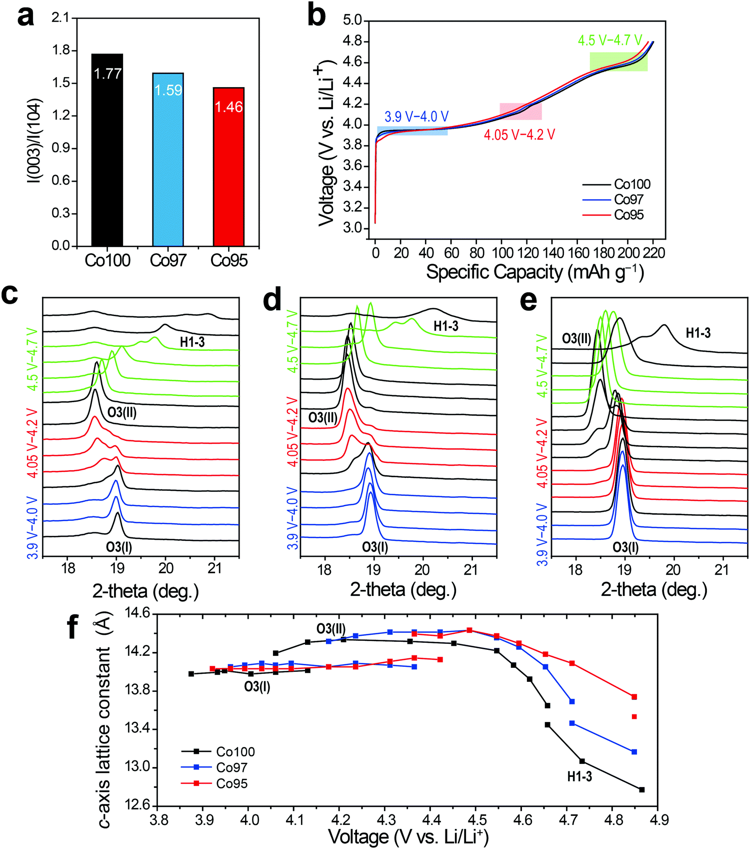 | ||
| Fig. 5 (a) Integrated intensity ratios of I(003)/I(104) for pristine Co100, Co97, and Co95. (b) Charging curves of Co100, Co97, and Co95 during in situ XRD analysis. In situ XRD (003) peak evolutions of (c) Co100, (d) Co97, and (e) Co95. (f) Calculated c-axis lattice constant with respect to voltage change. | ||
Cation mixing detected on ΔS profiles
ΔS was also measured to analyze the effect of Ni-doping on the structural changes. Fig. 6 displays the ΔS profiles of pre-cycled Co100, Co97, and Co95 with respect to the equilibrium voltage. In Fig. 6, the degree of ΔS swing, that is, the height difference between trough at 4.05 V and peak at 4.2 V (black arrow), significantly decreases with increasing Ni content. Considering that this specific voltage window is associated with the monoclinic phase with high Li-vacancy ordering in the atomic arrangement, this result can be related to Ni2+ ion positioning in the Li+ sites which lowers the ordering to some extent. As depicted in Fig. 2b, the presence of a highly ordered intermediate phase yields a low entropy state, which results in a sharp increase in the ΔS profile with crossing ΔS = 0. Upon Li–Ni cation mixing, the ordered monoclinic phase loses its ordering to some level, implying that the decreased trough-to-peak height with increasing Ni-doping amount reflects such cation mixing. Thus, the trough-to-peak height in the ΔS profile can serve as an indicator of cation mixing.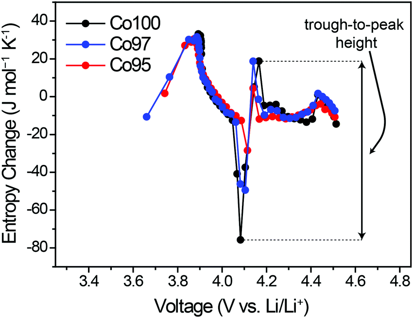 | ||
| Fig. 6 ΔS profiles of pre-cycled Co100, Co97, and Co95 measured throughout charging. | ||
Effect of high-voltage cycling on ΔS profile
In order to examine the effect of high-voltage cycling on the entropy behavior, the Co100, Co97, and Co95 electrodes were cycled with an upper cut-off voltage of 4.6 V versus Li/Li+. Fig. 7a shows the capacity retentions of those three electrodes for 50 cycles. In the case of Co100, the capacity decay is accelerated after 20 cycles, yielding only 50.5% capacity retention after 50 cycles. On the other hand, after the same number of cycles, Co97 and Co95 exhibit improved capacity retentions of 63.8% and 61.5%, respectively. The inferior cycling performance of Co100 is attributed to structural transformations involving cation exchange and phase transitions, which are accelerated in the high voltage range (Fig. S3, ESI†).4,46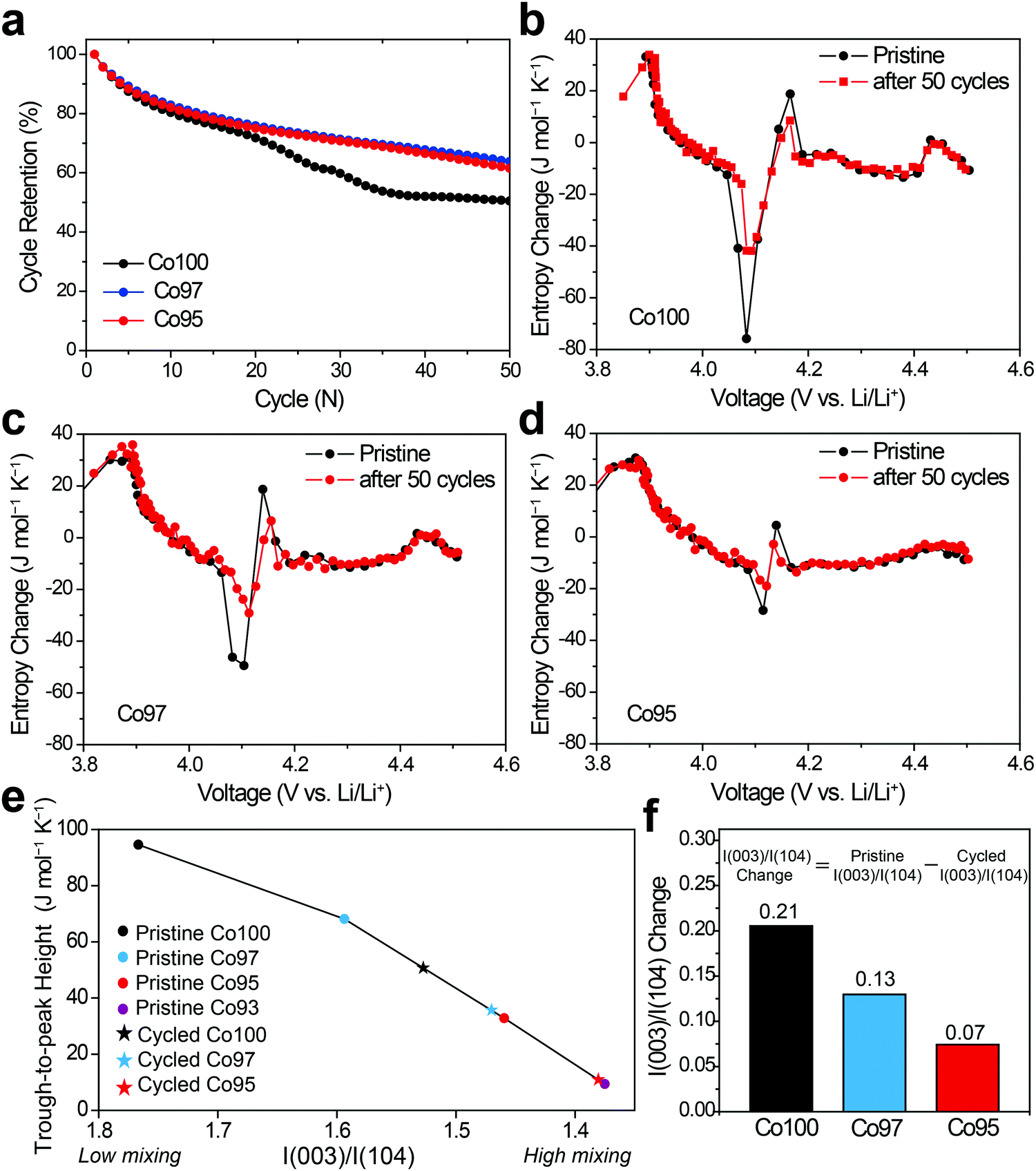 | ||
| Fig. 7 (a) Cycling performance of Co100, Co97, and Co95 during high voltage operation measured at 100 mA g−1. Mass loading of active material = 2.0 mg cm−2. (b–d) ΔS profiles of (b) Co100, (c) Co97, and (d) Co95 before and after 50 cycles. (e) Trough-to-peak heights in the monoclinic regime with respect to the intensity ratio of I(003)/I(104). (f) Changes in I(003)/I(104) ratio before and after cycles. | ||
The changes in the ΔS profiles before and after the cycling are plotted for Co100, Co97, and Co95 (Fig. 7b–d) in order to check if the initial cation mixing induced by Ni-doping is the primary reason for the superior cycling performance. Although the overall shapes of the ΔS profiles do not change much for all samples after 50 cycles, the change of trough-to-peak height in the monoclinic region of 4.05–4.2 V is different in a way that the height at the precycled state is the greatest for Co100 and declines with increasing the amount of Ni-doping. The trough-to-peak height differences before and after the cycling are 43.9, 32.5, and 16.7 for Co100, Co97, and Co95, respectively (Table S2, ESI†). Based on the logic described above, the decrease in the trough-to-peak height represents that the ordering has weakened as the cycle progresses. These results, in correlation with the cycling performance, indicate that initially lowered ordering of an intermediate phase by positioning transition metals in the Li layer can enhance high voltage structural stability by reducing internal strains.
To further correlate ΔS behavior with the structural ordering in a quantitative manner, the trough-to-peak height is plotted versus I(003)/I(104) from XRD analysis as shown in Fig. 7e. In the case of the pristine electrodes (marked with dots) that did not go through cycling, their trough-to-peak heights show a notable trend related to the degree of cation mixing; as I(003)/I(104) ratio decreases, the trough-to-peak height decreases. However, it is noted that the I(003)/I(104) ratios of the cycled electrodes are not suitable to quantify the degree of cation mixing because cycling causes particles in the planar electrode to become aligned along the (00l) direction irrespective of phase transition.47 Therefore, the I(003)/I(104) ratios of the cycled samples are linearly interpolated from the entropy change plots of the pristine samples, instead of directly plotting based on their actual I(003)/I(104) values. The inferred I(003)/I(104) ratios of the cycled samples (marked as stars) decrease compared to those before cycling, suggesting increased cation mixing during cycling. The trough-to-peak heights of the cycled Co100 and Co97 are both positioned between those of the pristine Co97 and Co95. To confirm the validity of this trend, pristine Co93 was additionally prepared and subjected to the same entropy analysis (Fig. S4, ESI†). Following the same trend, the trough-to-peak height of Co93 is lower than that of the pristine Co95, and the value of the cycled Co95 is between those of the pristine Co95 and pristine Co93. When I(003)/I(104) ratio is compared before and after 50 cycles, the difference before and after the cycling becomes larger with higher Co content (Fig. 7f); the I(003)/I(104) ratio differences before and after the cycling are 0.21, 0.13, and 0.07, respectively, for Co100, Co97, and Co95. The trend of trough-to-peak heights obtained from the series of samples and their cycled derivatives, linked with the I(003)/I(104) ratio changes, suggests that trough-to-peak height can serve as an indicator of the degree of cation mixing. Hence, the structural evolution of Ni-doped LCO can be non-destructively monitored during its lifetime via ΔS landscape. Furthermore, ΔS information can be a crucial component in detecting cycle life and safety weakness as these are heavily related to cation mixing.48,49 Thus, ΔS information can synergistically complement pre-existing lifetime and safety prediction models.50
Further analyses supporting entropymetry
In an effort to examine the validity of entropymetry, conventional analyses including XRD, Raman spectroscopy, X-ray photoelectron spectroscopy (XPS), and transmission electron microscopy (TEM) were further performed.The XRD analysis of the Co100, Co97, and Co95 electrodes before and after high voltage cycles indicates that the layered structures are well maintained and no additional phases were observed during cycling (Fig. 8a). However, the (003) peak position after cycling changes as the Ni content is varied. In the general case of layered metal oxide cathodes, over-potential during discharge inhibits the complete re-intercalation of Li ions, which leaves the c-axis lattice constant extended due to oxygen–oxygen repulsion between the oxygen-based lattice stacks.51 Such stretched c-axis is usually observed by a leftward (003) peak shift to a lower 2-theta value. On the contrary, the (003) peak of the cycled Co100 shifts to a higher 2-theta value compared to that of its pristine counterpart. This result indicates a decreased c-axis lattice constant due to irreversible structural deterioration by the slippage of metal oxide slabs at high voltages.15 The (003) peaks of the cycled Co97 and Co95 remain at lower 2-theta values than that of the cycled Co100. This trend in the peak shift reveals that Ni-doping makes the phase transition of LCO during high voltage cycling more reversible and suppresses unwanted structural changes. Hence, these XRD results are commensurate with the above ΔS results in that the ordering decreases more significantly with greater Co content.
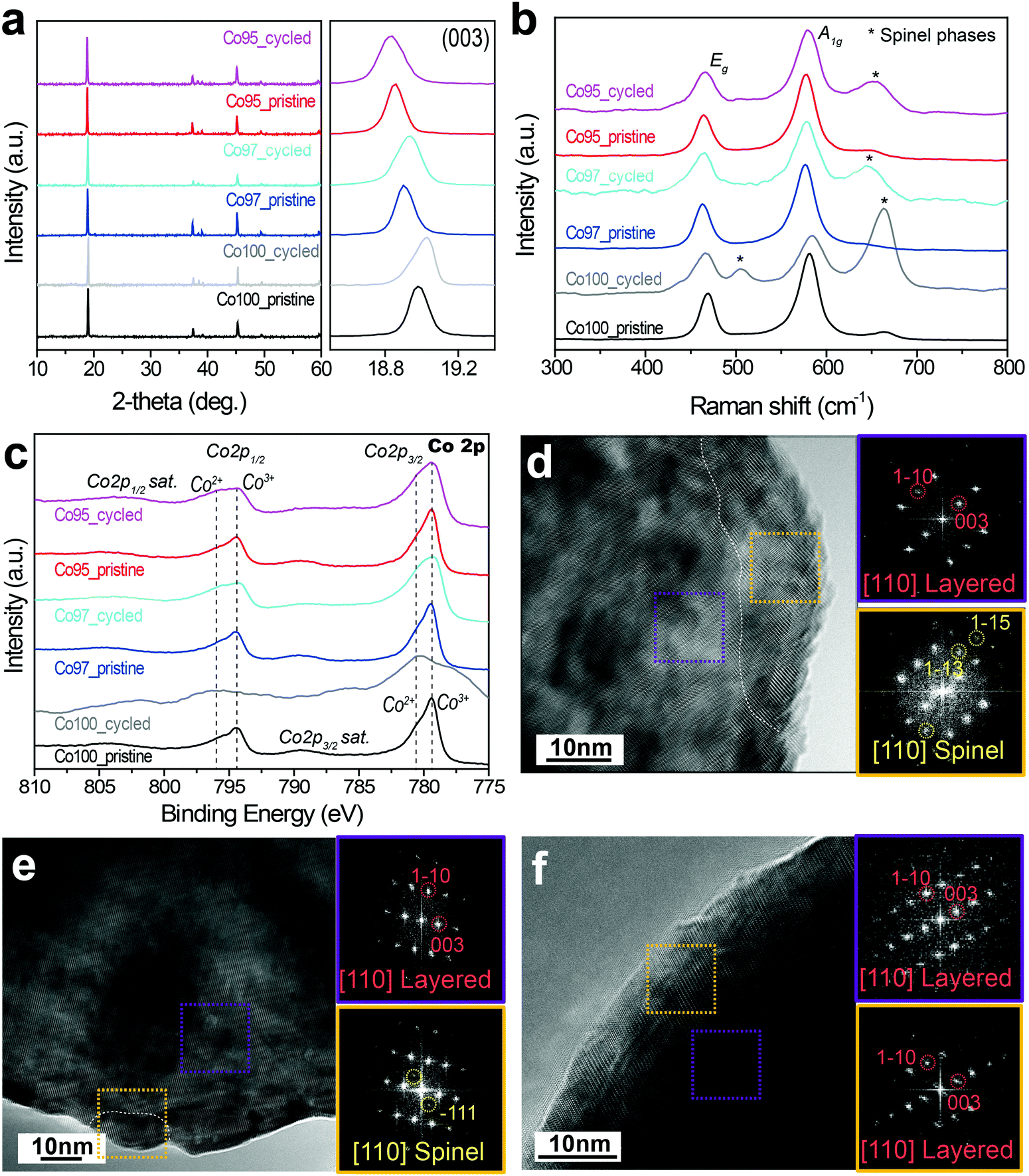 | ||
| Fig. 8 Characterization of Co100, Co97, and Co95 electrodes before and after 50 cycles with high voltage cut-off. (a) Overall XRD profiles and their magnified views around (003) peaks. (b) Raman scattering spectra of the same electrodes. (c) XPS spectra in Co 2p. High-resolution TEM images of (d) Co100, (e) Co97, and (f) Co95 after 50 cycles and their corresponding fast Fourier transformation (FFT) patterns from the selected areas marked in dotted boxes. | ||
Raman spectroscopy was employed to investigate the local structural disorder related to the phase transformation. Fig. 8b shows the Raman spectra of the Co100, Co97, and Co95 electrodes before and after 50 cycles. The Raman spectra of pristine LCO-based samples show two main peaks at around 486 and 585 cm−1 corresponding to Eg and A1g active Raman modes, respectively.52,53 In addition, a weak peak at 665 cm−1 was detected, which can be assigned to spinel phases such as Co3O4 and LixCo2O4 originating from the loss of Li during synthesis.54 After cycling, all three electrodes show relatively stronger spinel phase peaks at around 505 and 665 cm−1, representing irreversible phase transition to spinel phases during cycling. The intensity of the peaks assigned to spinel phases (Co3O4 and LixCo2O4) is the highest for Co100, which can be explained by the fact that the cation mixing of the Ni-doped samples suppresses the structural degradation during cycling. Therefore, the Raman spectra portray a consistent picture with the entropy analysis such that Ni-doping contributes to maintaining the lattice framework against severe irreversible structural transformation involving the electrostatic repulsion of the oxygen lattice.
Fig. 8c displays the Co 2p XPS spectra of the three electrodes before and after the high voltage cycling. As shown in Fig. 8c, the Co 2p spectra show two spin–orbit peaks (Co 2p3/2 at 779.5 eV and Co 2p1/2 at 794.5 eV) along with their shake-up satellite peaks. The Co 2p3/2 peak of Co100 mainly consists of Co3+ (779.5 eV) with a slight portion of Co2+ (780.5 eV).55,56 This Co2+ portion in the pristine sample seemingly arises53 from the formation of impurity phases due to the evaporation of Li during synthesis. After cycles with 4.6 V cut-off, the peak corresponding to Co2+ at Co 2p3/2 greatly increases and its satellite peak also shifts towards lower binding energy. These results are consistent with the formation of spinel phases such as Co3O4 and LixCo2O4. However, unlike Co100, the Co2+ and satellite peaks of Co97 and Co95 do not change significantly.
Fig. 8d–f show the high-resolution TEM images of Co100, Co97, and Co95 after the high voltage cycles, respectively. The yellow and purple boxes correspond to selected areas in the surface and bulk, respectively. The bulk FFT pattern of the cycled Co100 taken along the [110] zone axis exhibits a diffraction pattern indicative of a layered structure, while additional spots appear in its surface FFT pattern. These additional spots marked in yellow circles correspond to the (1−13) and (1−15) lattice planes of spinel phases. The spinel atomic arrangement is observed along the surface of each Co100 particle, as the phase borderline is drawn in white. By contrast, the spinel phase is less frequently observed around the surface of Co97 (Fig. 8e), and is not observed at all in the case of Co95 (Fig. 8f). These TEM results are consistent with those of the ΔS analysis in that Ni-doping inhibits structural degradation to spinel phases in high voltage cycles.
Conclusions
High voltage LCO is highly desired owing to the advantages of LCO related to an in-depth understanding of its structure and interface. In this study, we have demonstrated entropymetry as a useful non-destructive diagnostic tool for monitoring LCO and its Ni-doped analogues at different states of charge. In particular, the entropymetry captures the monoclinic phase and its varied states by different degrees of Ni-doping by detecting the change of the configurational ordering involving Li–Ni cation mixing. The extended cycle life from Ni-doping can be understood in relation to the enhanced structural stability. Beyond the LCO family, entropymetry can be applied to a wide range of battery electrode materials that undergo changes in ordering during cycling. We foresee that entropymetry can serve as a key component of future battery management systems (BMS) that reflect the chemical states of electrode materials.Experimental
Synthesis of LiCoO2-based materials
The Co100, Co97, and Co95 samples were synthesized via a sol–gel process. Lithium nitrate (LiNO3, Sigma-Aldrich), cobalt(II) nitrate hexahydrate (Co(NO3)2·6H2O, Sigma-Aldrich) and nickel(II) nitrate hexahydrate (Ni(NO3)2·6H2O, Sigma-Aldrich) were used as reagents. 0.696 g of LiNO3 and metal (Co and Ni) nitrate hexahydrate were added in stoichiometric proportions to 50 mL of deionized water. The molar ratio of [Li]/[M] (M = Co or Co + Ni) was 1.01 to compensate for lithium loss during heat treatment. After adding 3.862 g of citric acid (C6H8O7, Sigma-Aldrich) as a chelating agent, the solutions were stirred at 90 °C for 18 h until viscous gels were formed. The gel precursors were dried in a convection oven at 110 °C for 2 h. After calcination in air at 400 °C for 1 h, the precursors were pelletized and then sintered in air at 800 °C for 24 h.Materials characterization
Synchrotron-based in situ XRD spectra were collected at the beamline 1D of Pohang Accelerator Laboratory (PAL) using a MAR345 image plate detector. A 2032-type coin cell with a 5 mm hole at the center was used as an in situ XRD cell and the hole was sealed with Kapton film. This coin cell was cycled at 30 mA g−1 (1C = 200 mA g−1) and the beam exposure time was 10 s for each scan. A total of 288 scans were collected for each charge and the images were converted to diffraction patterns using the Fit2D software. The 2θ angles of all XRD spectra were converted to the 2θ scale of the conventional Cu-Kα based radiation with λ = 1.54 Å. The elemental analysis was performed using an ICP-OES spectrometer (iCAP 6300 Duo, Thermo Scientific). The morphology of samples was examined by field-emission SEM (JSM-7800F Prime, JEOL Ltd) and Cs-TEM (JEM-ARM200F, JEOL Ltd). The XRD spectra of various electrodes before and after cycles were obtained using a powder X-ray diffractometer (SmartLab, Rigaku). The SEM, Cs-TEM and powder XRD analyses were performed at the National Center for Inter-university Research Facilities (NCIRF) at Seoul National University. The elemental compositions of electrodes were characterized using XPS (K-alpha, Thermo VG Scientific), and Raman spectra were collected using a Raman spectrometer (LabRAM HV Evolution, Horiba) with 532 nm laser.Entropy measurements
For ΔS measurement, temperature and voltage changes were pre-programmed and monitored using an incubator (IL-11, JEIO TECH) and a battery tester (PEBC05-0.01, PNE solution), respectively. OCV was monitored at each SOC while the temperature was varied. For the temperature variation, the incubator temperature was first maintained at 30 °C for 150 min and then lowered to 20 °C and kept for 90 min, followed by returning the temperature to 30 °C and staying there for 60 min. This measurement was performed again after moving to the next measurement point by galvanostatic scanning at 0.01C for 30 min and was continued until the OCV reached the cut-off voltage of 4.5 V. For accurate ΔS measurement, baseline correction was given to the OCV profile by linearly fitting the baseline between the OCV values measured at the first 30 °C and the returned 30 °C, and the value on the baseline was used to obtain the OCV change at 20 °C (see voltage profile in Fig. S5, ESI†).Electrochemical tests
For the electrode fabrication, a slurry was first prepared by dispersing active material (Co100, Co97 or Co95), polyvinylidene fluoride (PVDF, Aldrich, Mw ∼ 534000), and super P (TIMCAL) in N-methyl-pyrrolidone at a mass ratio of 8:1:1. The slurry was then cast onto an aluminum foil and dried under vacuum at 70 °C for 12 h. The mass loading of the active material was 2 mg cm−2. Electrodes were punched into circular discs for the fabrication of 2032 coin-type cells.
The coin cells were prepared in an Ar-filled glove box by assembling a Celgard 2400 separator, the LiCoO2-based electrode (working electrode), and Li metal foil (reference/counter electrode). 1 M lithium hexafluorophosphate (LiPF6) solution in a mixture of ethylene carbonate (EC) and dimethyl carbonate (DMC) (EC:DMC = 1:1, vol/vol) (PANAX E-TEC) was used as electrolyte. For battery testing, the galvanostatic mode was applied using a battery tester (PEBC05-0.01, PNE solution). The cell tests were conducted in the potential range of 3.0–4.6 V vs. Li/Li+ with constant current (CC) mode for both charge and discharge. For typical galvanostatic cycling tests, the coin cells were pre-cycled at 10 mA g−1 for 2 cycles, and the subsequent cycles were charged and discharged at 0.6C (1C = 170 mA g−1).
Author contributions
H. J. K., Y. P., and J. W. C. designed the research. H. J. K., Y. P., and Y. K. carried out the synthesis and electrochemical measurements. H. J. K., Y. P., Y. K., J. S., Y.-H. K., and H.-S. A. performed data analysis. H. J. K., Y. P., Y. K., J. S. and J. W. C. co-wrote the manuscript. R. Y. and J. W. C. supervised the research. All authors discussed the results and commented on the manuscript.Conflicts of interest
There are no conflicts to declare.Acknowledgements
J. W. C. acknowledges financial support from a National Research Foundation of Korea grant (NRF-2018R1A2A1A19023146). The authors also acknowledge the next generation subminiature IoT technology program (2018-0-00804) by Ministry of Science and ICT, Republic of Korea as well as technical support with the 1D (1D-XRS) beam lines at Pohang Accelerating Laboratory (PAL).Notes and references
- J. Hassoun, S. Panero, P. Reale and B. Scrosati, Adv. Mater., 2009, 21, 4807–4810 CrossRef CAS PubMed.
- J.-M. Tarascon and M. Armand, Nature, 2001, 414, 359–361 CrossRef CAS PubMed.
- J. B. Goodenough and Y. Kim, Chem. Mater., 2009, 22, 587–603 CrossRef.
- J. Vetter, P. Novák, M. R. Wagner, C. Veit, K.-C. Möller, J. Besenhard, M. Winter, M. Wohlfahrt-Mehrens, C. Vogler and A. Hammouche, J. Power Sources, 2005, 147, 269–281 CrossRef CAS.
- S. K. Jung, H. Gwon, J. Hong, K. Y. Park, D. H. Seo, H. Kim, J. Hyun, W. Yang and K. Kang, Adv. Energy Mater., 2014, 4, 1300787 CrossRef.
- G. Chen, X. Song and T. J. Richardson, Electrochem. Solid-State Lett., 2006, 9, A295–A298 CrossRef CAS.
- D. J. Miller, C. Proff, J. Wen, D. P. Abraham and J. Bareño, Adv. Energy Mater., 2013, 3, 1098–1103 CrossRef CAS.
- H. Wang, Y. I. Jang, B. Huang, D. R. Sadoway and Y. M. Chiang, J. Electrochem. Soc., 1999, 146, 473–480 CrossRef CAS.
- A. Boulineau, L. Croguennec, C. Delmas and F. Weill, Chem. Mater., 2009, 21, 4216–4222 CrossRef CAS.
- L. Dahéron, R. Dedryvere, H. Martinez, M. Ménétrier, C. Denage, C. Delmas and D. Gonbeau, Chem. Mater., 2007, 20, 583–590 CrossRef.
- M. Ménétrier, I. Saadoune, S. Levasseur and C. Delmas, J. Mater. Chem., 1999, 9, 1135–1140 RSC.
- W.-S. Yoon, C. P. Grey, M. Balasubramanian, X.-Q. Yang and J. McBreen, Chem. Mater., 2003, 15, 3161–3169 CrossRef CAS.
- W.-S. Yoon, M. Balasubramanian, K. Y. Chung, X.-Q. Yang, J. McBreen, C. P. Grey and D. A. Fischer, J. Am. Chem. Soc., 2005, 127, 17479–17487 CrossRef CAS PubMed.
- D. Ostrovskii, F. Ronci, B. Scrosati and P. Jacobsson, J. Power Sources, 2001, 94, 183–188 CrossRef CAS.
- T. Ohzuku and A. Ueda, J. Electrochem. Soc., 1994, 141, 2972–2977 CrossRef CAS.
- M. Morcrette, Y. Chabre, G. Vaughan, G. Amatucci, J.-B. Leriche, S. Patoux, C. Masquelier and J. Tarascon, Electrochim. Acta, 2002, 47, 3137–3149 CrossRef CAS.
- X.-Q. Yang, J. McBreen, W.-S. Yoon and C. P. Grey, Electrochem. Commun., 2002, 4, 649–654 CrossRef CAS.
- Y. Reynier, J. Graetz, T. Swan-Wood, P. Rez, R. Yazami and B. Fultz, Phys. Rev. B: Condens. Matter Mater. Phys., 2004, 70, 174304 CrossRef.
- A. Urban, D.-H. Seo and G. Ceder, npj Comput. Mater., 2016, 2, 16002 CrossRef CAS.
- V. V. Viswanathan, D. Choi, D. Wang, W. Xu, S. Towne, R. E. Williford, J.-G. Zhang, J. Liu and Z. Yang, J. Power Sources, 2010, 195, 3720–3729 CrossRef CAS.
- R. E. Williford, V. V. Viswanathan and J.-G. Zhang, J. Power Sources, 2009, 189, 101–107 CrossRef CAS.
- K. Maher and R. Yazami, J. Power Sources, 2014, 247, 527–533 CrossRef CAS.
- K. Jalkanen, T. Aho and K. Vuorilehto, J. Power Sources, 2013, 243, 354–360 CrossRef CAS.
- P. J. Osswald, M. del Rosario, J. Garche, A. Jossen and H. E. Hoster, Electrochim. Acta, 2015, 177, 270–276 CrossRef CAS.
- K. Maher and R. Yazami, Electrochim. Acta, 2013, 101, 71–78 CrossRef CAS.
- X.-F. Zhang, Y. Zhao, Y. Patel, T. Zhang, W.-M. Liu, M. Chen, G. J. Offer and Y. Yan, Phys. Chem. Chem. Phys., 2017, 19, 9833–9842 RSC.
- R. Yazami, Y. Reynier and B. Fultz, ECS Trans., 2006, 1, 87–96 CAS.
- G. Amatucci, J. Tarascon and L. Klein, Solid State Ionics, 1996, 83, 167–173 CrossRef CAS.
- Z. Chen, Z. Lu and J. Dahn, J. Electrochem. Soc., 2002, 149, A1604–A1609 CrossRef CAS.
- M. Zou, M. Yoshio, S. Gopukumar and J.-i. Yamaki, Chem. Mater., 2003, 15, 4699–4702 CrossRef CAS.
- S. Castro-García, A. Castro-Couceiro, M. Senarıs-Rodrıguez, F. Soulette and C. Julien, Solid State Ionics, 2003, 156, 15–26 CrossRef.
- S. Gopukumar, Y. Jeong and K. B. Kim, Solid State Ionics, 2003, 159, 223–232 CrossRef CAS.
- S.-T. Myung, N. Kumagai, S. Komaba and H.-T. Chung, Solid State Ionics, 2001, 139, 47–56 CrossRef CAS.
- W. Cho, S. Myeong, N. Kim, S. Lee, Y. Kim, M. Kim, S. J. Kang, N. Park, P. Oh and J. Cho, Adv. Mater., 2017, 29, 1605578 CrossRef PubMed.
- W. M. Haynes, CRC Handbook of Chemistry and Physics, CRC press, 2014 Search PubMed.
- G. Amatucci, J. Tarascon and L. Klein, J. Electrochem. Soc., 1996, 143, 1114–1123 CrossRef CAS.
- L. Liu, L. Chen, X. Huang, X.-Q. Yang, W.-S. Yoon, H. Lee and J. McBreen, J. Electrochem. Soc., 2004, 151, A1344–A1351 CrossRef CAS.
- Y. Shao-Horn, S. Levasseur, F. Weill and C. Delmas, J. Electrochem. Soc., 2003, 150, A366–A373 CrossRef CAS.
- A. Van der Ven, M. Aydinol, G. Ceder, G. Kresse and J. Hafner, Phys. Rev. B: Condens. Matter Mater. Phys., 1998, 58, 2975 CrossRef CAS.
- M. Arroyo y de Dompablo, C. Marianetti, A. Van der Ven and G. Ceder, Phys. Rev. B: Condens. Matter Mater. Phys., 2001, 63, 144107 CrossRef.
- X. Lu, Y. Sun, Z. Jian, X. He, L. Gu, Y.-S. Hu, H. Li, Z. Wang, W. Chen and X. Duan, Nano Lett., 2012, 12, 6192–6197 CrossRef CAS PubMed.
- J. N. Reimers and J. R. Dahn, J. Electrochem. Soc., 1992, 139, 2091–2097 CrossRef CAS.
- W. Liu, P. Oh, X. Liu, M. J. Lee, W. Cho, S. Chae, Y. Kim and J. Cho, Angew. Chem., Int. Ed., 2015, 54, 4440–4457 CrossRef CAS PubMed.
- J. Reimers, J. Dahn and U. Von Sacken, J. Electrochem. Soc., 1993, 140, 2752–2754 CrossRef CAS.
- A. Yano, M. Shikano, A. Ueda, H. Sakaebe and Z. Ogumi, J. Electrochem. Soc., 2017, 164, A6116–A6122 CrossRef CAS.
- M. M. Thackeray, J. Electrochem. Soc., 1995, 142, 2558–2563 CrossRef CAS.
- R. Weber, C. R. Fell, J. Dahn and S. Hy, J. Electrochem. Soc., 2017, 164, A2992–A2999 CrossRef CAS.
- H.-J. Noh, S. Youn, C. S. Yoon and Y.-K. Sun, J. Power Sources, 2013, 233, 121–130 CrossRef CAS.
- S.-M. Bak, E. Hu, Y. Zhou, X. Yu, S. D. Senanayake, S.-J. Cho, K.-B. Kim, K. Y. Chung, X.-Q. Yang and K.-W. Nam, ACS Appl. Mater. Interfaces, 2014, 6, 22594–22601 CrossRef CAS PubMed.
- J. Zhang and J. Lee, J. Power Sources, 2011, 196, 6007–6014 CrossRef CAS.
- G. G. Amatucci, J. M. Tarascon and L. C. Klein, Solid State Ionics, 1996, 83, 167–173 CrossRef CAS.
- M. Inaba, Y. Iriyama, Z. Ogumi, Y. Todzuka and A. Tasaka, J. Raman Spectrosc., 1997, 28, 613–617 CrossRef CAS.
- M. Inaba, Y. Todzuka, H. Yoshida, Y. Grincourt, A. Tasaka, Y. Tomida and Z. Ogumi, Chem. Lett., 1995, 889–890 CrossRef CAS.
- H. Porthault, F. Le Cras and S. Franger, J. Power Sources, 2010, 195, 6262–6267 CrossRef CAS.
- R. Dedryvere, S. Laruelle, S. Grugeon, P. Poizot, D. Gonbeau and J.-M. Tarascon, Chem. Mater., 2004, 16, 1056–1061 CrossRef CAS.
- L. Dahéron, H. Martinez, R. Dedryvere, I. Baraille, M. Ménétrier, C. Denage, C. Delmas and D. Gonbeau, J. Phys. Chem. C, 2009, 113, 5843–5852 CrossRef.
Footnotes |
| † Electronic supplementary information (ESI) available. See DOI: 10.1039/c9ee02964h |
| ‡ H. J. Kim and Y. Park contributed equally to this work. |
| This journal is © The Royal Society of Chemistry 2020 |