
 Open Access Article
 This Open Access Article is licensed under a Creative Commons Attribution-Non Commercial 3.0 Unported Licence
A deactivation mechanism study of phosphorus-poisoned diesel oxidation catalysts: model and supplier catalysts
Aiyong
Wang
 a,
Jihao
Wang
a,
Sahil
Sheti
a,
Sandra
Dahlin
b,
Joonsoo
Han
a,
Jungwon
Woo
a,
Kunpeng
Xie
c,
Lars J.
Pettersson
b and
Louise
Olsson
*a
a,
Jihao
Wang
a,
Sahil
Sheti
a,
Sandra
Dahlin
b,
Joonsoo
Han
a,
Jungwon
Woo
a,
Kunpeng
Xie
c,
Lars J.
Pettersson
b and
Louise
Olsson
*a
aChemical Engineering, Competence Centre for Catalysis, Chalmers University of Technology, Gothenburg, Sweden. E-mail: louise.olsson@chalmers.se
bDepartment of Chemical Engineering, KTH Royal Institute of Technology, SE-100 44 Stockholm, Sweden
cVolvo Group Trucks Technology, SE-405 08, Gothenburg, Sweden
First published on 15th July 2020
Abstract
The effect of phosphorus poisoning on the catalytic behavior of diesel oxidation catalysts was investigated over model and supplier monolith catalysts, i.e., Pd–Pt/Al2O3. The results of ICP and XPS from the vapor-phase poisoning over model catalysts suggested that the temperature of phosphorus poisoning affects both the overall content of phosphorus and the dispersion of phosphorus (i.e., inlet/outlet and surface/bulk). Phosphorus oxide (P2O5), metaphosphate (PO3−), and phosphate (PO43−) were identified in the poisoned model and supplier catalysts. The distribution of these species on poisoned model catalysts was highly dependent on the poisoning temperature, i.e., a higher temperature resulted in a higher concentration of PO43−. The outlets of the monoliths contained more PO43− and less P2O5 than the inlets. Both active sites and surface OH groups on model and supplier catalysts were contaminated upon phosphorus poisoning. It is found that PO43− had a stronger influence on the active sites than P2O5. One significant finding in this study is that the vapor-phase phosphorus poisoning could be a practical and cost efficient approach to simulate an accelerated aging/poisoning process.
1. Introduction
Internal combustion engines (ICE) produce emissions such as particulate matter (PM),1,2 carbon monoxide (CO),3,4 hydrocarbons (HCs),5,6 and nitrogen oxides (NOx).7–9 Fortunately, automotive emissions have been significantly reduced with the application and development of exhaust after treatment systems (EATS). For example, three-way catalysts (TWC) were successfully introduced in stoichiometric gasoline engines in the late 1980s,10 resulting in significant reduction of the emission of CO, HCs, and NOx from gasoline vehicles. For diesel engines, the diesel oxidation catalysts (DOCs),11,12 or lean NOx trap (LNT),13,14 is capable of oxidizing CO and HCs, where LNT is typically applied in light-duty vehicles and is also used for NOx removal in mixed lean conditions. Urea selective catalytic reduction (SCR) is commonly used for removing NOx from diesel engines.15Despite the significant catalytic oxidation performance of DOCs, various poisoning species, e.g., alkali or alkaline earth metals (Zn, Ca, and Mg), sulfur, and phosphorus (P), are normally detected on the surface of monoliths wash coated with DOCs after long-distance driving.12,16,17 Of these, phosphorus derived from engine oil is one of the most difficult contaminations that can permanently deactivate DOCs due to the difficulty to regenerate upon thermal treatment.18,19 The use of alternative fuels, e.g., biodiesel, has been gaining increasing attention in order to meet stringent CO2 emission requirements.20 However, phosphorus can also be present in some biofuels because phospholipids are a major component of the cell membranes in raw biomass materials.20 As described above, phosphorus results in the risk that after treatment catalysts will be poisoned, especially the front component, i.e., the DOC.
Several groups have conducted phosphorus-poisoning investigations over catalytic components, such as the DOC, and selective catalytic reduction (SCR) catalysts.12,21–24 Kröger et al.25 have found that phosphorus poisoning results in a decrease in the specific surface area and pore volume in DOCs and an increase in the average pore size of the catalysts. Toops and coworkers18 have studied the deactivation mechanism of Pt/CeO2/Al2O3 upon phosphorus poisoning, where phosphorus primarily in the form of aluminum phosphate was found to accumulate mainly at the front of the DOC. Anguita et al.12 have also conducted a study of the effect of impurities (Na, K, Ca and P) from biofuel on the performance of a DOC catalyst (i.e., Pt, Pd/CeZrO2/La–Al2O3). They found that CO and C3H6 oxidation were enhanced, while NO to NO2 conversion decreased in the presence of P species. Deactivation of Pt/SiO2–ZrO2 as a DOC catalyst caused by sulfur and phosphorus has been studied by Keiski and coworkers.19 Sulfur was found to decrease the amount of adsorbed phosphorus and thus, inhibit the poisoning effect of phosphorus. Our group21 recently examined the deactivation of Cu/SSZ-13 with vapor-phase phosphorus poisoning (100 ppm H3PO4). Three major P species were identified and attributed to phosphorus oxide (P2O5), metaphosphate (PO3−), and phosphate (PO43−), where metaphosphate was the main compound on all the poisoned samples. The effect of biodiesel-derived contaminants on V2O5–WO3/TiO2 catalysts have also been analyzed by Dahlin et al.20 The deactivation caused by alkali was reduced with phosphorus and sulfur, which can be explained by the formation of phosphates and sulfates to prevent the interaction of the alkali metals with the vanadium active centers. This group26 also found that an upstream DOC component protected a downstream SCR catalyst by seizing phosphorus, resulting in less phosphorus to interact with the SCR catalyst.
Even though the studies mentioned above have demonstrated the influence of phosphorus on DOCs, there are to our knowledge no published studies that investigate the effect of the temperature of phosphorus-poisoning. Comparisons between model and supplier DOCs during phosphorus poisoning have not been found in the literature either. Therefore, in this work, the deactivation of DOCs caused by phosphorus poisoning was investigated using both model and supplier catalysts. Specifically, the effect of poisoning temperature was systematically explored. The deactivation mechanism was studied using different techniques, such as ICP-AES, BET surface area, SEM-EDX mapping, XPS, in situ DRIFTS, NO-TPD, and H2-TPR.
2. Experimental methods
2.1. Catalyst preparation
The model Pt–Pd/Al2O3 catalyst was prepared using the wet impregnation method, where γ-Al2O3 was employed as the support. To prepare the sample powder, γ-Al2O3 (Puralox SBa 200) was calcined for 2 hours at 900 °C in an oven. Subsequently, Pt precursor solution was prepared from Pt(NO3)2 (Heraeus GmbH, 13.82 wt% Pt), which was diluted by adding MilliQ water, and a Pd precursor solution was prepared with a dilution of Pd(NO3)2 (Johnson Matthey, 7.3 wt% Pd) in MilliQ water. Thereafter, a Pt precursor solution was mixed dropwise with the Al2O3 support followed by drying at 120 °C overnight and calcination in the furnace at 500 °C for 2 hours, using a temperature ramp of 5 °C min−1 to the set point. Once the sample was calcined, it was impregnated with the Pd precursor. The final catalyst material was dried and calcined using the same conditions as for Pt impregnation.The as-prepared powder sample was used to washcoat on the commercial monolith for vapor-phase phosphorus poisoning (section 2.2) and the catalytic activity tests (section 2.3). The details of the procedure can be found in the literature.27 The size of monolith was 2 cm in length and 1.5 cm in diameter with a cell density of 400 cpsi. The powder loaded in the monolith was around 300 mg, including 95% catalyst and 5% boehmite, where boehmite was used as a binder. After that, the obtained monoliths were further calcined in the static furnace for 2 hours at 500 °C (5 °C min−1).
Supplier monolith catalysts were also utilized in this study (diameter = 1.5 cm, length = 3 cm). The supplier catalysts contained 20 g ft−3 noble metals with a Pt![[thin space (1/6-em)]](https://www.rsc.org/images/entities/char_2009.gif) :Pd ratio of 2:1.
:Pd ratio of 2:1.
2.2. Aging/poisoning of supplier catalysts using a diesel burner
The supplier catalysts were aged with biodiesel exhausts using a diesel burner aging rig. In each aging experiment, which lasted around 150 h, approximately one barrel (200 dm3) of biodiesel was used. During this time, the temperature was kept at 440–455 °C, and the oxygen content was around 7%. The biodiesel fuel used in the experiments was a fatty acid methyl ester (FAME) that fulfilled the EN14214 standard. It contained <5 ppm sulfur, <1 ppm P, <5 ppm sodium + potassium, and <5 ppm magnesium + calcium. Trace amounts of zinc can also be present in biodiesel.20One aging experiment used pure biodiesel, while phosphorus was added to the biodiesel in two of the aging experiments. Phosphorus was added in the form of triphenyl phosphate (TPP) to a concentration of either 93 ppm P (targeting a lifetime exposure of phosphorus) or 11 ppm P. The biodiesel containing 11 ppm P was additionally doped with sulfur, to a concentration of 11 ppm S. The DOCs from these aging experiments are denoted Supplier_FAME, Supplier_P93, and Supplier_P11_S11, respectively. A fresh, degreened catalyst was used as a reference (denoted Supplier_Fresh). More details about the biodiesel exposures can be found in the paper by Dahlin et al.,26 which evaluates SCR catalysts that were aged together with the DOCs in the diesel burner rig.
2.3. Phosphorus poisoning of model monolith catalysts in flow reactor
A diluted aqueous H3PO4 solution acquired from 85% H3PO4 (Merck) was used in the experiments that simulated phosphorus poisoning. The H3PO4 solution was added into the flow reactor, where details can be found in our earlier publication.21 We conducted different tests using 2000 ppm H3PO4 solution and 200 °C was found to be enough for the H3PO4 solution evaporating. The gas mixture consisted of 100 ppm H3PO4, 5% H2O, 8% O2 in Ar using a total gas flow of 1200 ml min−1. The gas lines were maintained at 200 °C to avoid the condensation of both water and H3PO4. A series of three poisoning temperatures (300, 400, and 500 °C) were used to study the effect of temperature during phosphorus poisoning. The poisoning injection period was 24 hours for all three experiments. The samples were denoted DOC_Fresh, DOC_300, DOC_400, and DOC_500, respectively. The performance of the P-poisoned catalyst were tested after each poisoning experiment using the activity measurements described in section 2.4.2.4. Catalytic activity measurements
The performance of the monolith samples was tested in a flow reactor. A LabVIEW software was used to control the whole system, including the flow and the temperature. The details can be found in our prior study.21 The monolith catalysts were located downstream in the tubular reactor. A thermocouple was placed around 10 mm in front of the monolith to measure/control the reactor temperature, while another thermocouple was located in the middle of the monolith to monitor the temperature of the monolith. This monolith temperature is the temperature used in the conversion graphs. The concentrations of the gases (e.g., NO, CO, C3H6, C3H8, and H2O) were recorded every second using an MKS Multi-gas 2030 FTIR spectrometer.To test the model catalysts, the catalysts were first degreened by exposing them to 1% H2 in Ar at 500 °C for 30 min, after which the reactor was heated to 600 °C followed by 200 ppm C3H6, 10% O2, and 5% H2O in Ar for 2 hours. Note that the pretreatment was only conducted for the fresh model catalyst and all the fresh model catalysts used for phosphorus poisoning as described in section 2.3 were first pretreated. Thereafter, the activity was measured in three different experiments with different gas compositions. The composition of the gases in the first experiment (CO oxidation, 2CO + O2 → 2CO2) consisted of 100 ppm CO, 10% O2, 5% H2O with Ar as the carrier gas. The gas mixture was introduced at 500 °C and kept during the entire experiment, which consisted of: (i) maintaining the temperature at 500 °C for 15 minutes, (ii) cooling down at a rate of 5 °C min−1 to 100 °C, (iii) maintaining the temperature at 100 °C for 15 minutes, (iv) heating at a rate of 5 °C min−1 up to 500 °C, and (v) maintaining the temperature at 500 °C for 15 minutes. The same procedure was repeated for experiments 2–5, but with different gas compositions. The gas composition in the experiments 2–4 was changed to 1000 ppm NO (experiment 2) or 100 ppm C3H6 (experiment 3) or 100 ppm C3H8 (experiment 4), 10% O2, 5% H2O with inert balance Ar. In the last experiment, a more complex mixture of gases was used (100 ppm CO, 1000 ppm NO, 100 ppm C3H6, 100 ppm C3H8, 10% O2, 5% H2O in Ar). The total gas flow was maintained at 1200 mL min−1 in all experiments. This activity test for the model catalysts was performed for fresh samples and P-poisoned samples. Note that between two experiments, the catalyst was maintained at 500 °C in 10% O2, 5% H2O with Ar for 30 min.
The same gas compositions as for the model catalysts was used to test the supplier monolith catalysts, except that the total flow rate used was 1800 ml min−1 in order to reach the same space velocity, i.e., 22100 h−1, as for the model monoliths (supplier monoliths were longer). Note that the catalysts were heated only to 300 °C since a small amount of sulfur was present in the supplier catalysts after aging with the burner. This was done to minimize the desorption of residual sulfur. Also, no pretreatment was done for the supplier catalysts before the activity tests to avoid sulfur desorption. Note that between two experiments, the supplier catalyst was maintained at 300 °C in 10% O2, 5% H2O with Ar for 30 min.
2.5. Catalyst characterization
The Pd, Pt, P, and S contents of the catalysts were measured using inductively coupled plasma atomic emission spectroscopy (ICP-AES) performed by ALS Scandinavia AB. The samples were prepared in powder from crushed monoliths. The washcoat loading on the model catalysts accounted for approximately a quarter of the mass (300 mg washcoat + 900 mg blank monolith). The amounts of washcoat for the supplier samples are unknown, and we assume the similar ratio as for our model catalysts. Therefore, the mass percentages presented in Table 1 were obtained from the ICP results multiplied by a factor of 4.| Sample | Pd content (wt%) | Pt content (wt%) | P content (wt%) | S content (wt%) | |
|---|---|---|---|---|---|
| DOC_300 | Inlet | 0.48 | 0.44 | 8.1 | — |
| Outlet | 0.48 | 0.40 | 1.1 | — | |
| DOC_400 | Inlet | 0.44 | 0.40 | 12.8 | — |
| Outlet | 0.44 | 0.44 | 10.8 | — | |
| DOC_500 | Inlet | 0.40 | 0.36 | 12.6 | — |
| Outlet | 0.44 | 0.40 | 11.6 | — | |
| Supplier_FAME | Inlet | 0.20 | 0.44 | 0.16 | 0.40 |
| Outlet | 0.24 | 0.40 | 0.04 | 0.56 | |
| Supplier_P11_S11 | Inlet | 0.16 | 0.40 | 5.0 | <0.02 |
| Outlet | 0.20 | 0.44 | 1.8 | 0.16 | |
| Supplier_P93 | Inlet | 0.20 | 0.36 | 9.6 | <0.02 |
| Outlet | 0.16 | 0.36 | 8.2 | <0.02 |
EDX mapping under SEM observation was performed using a Quanta200 ESEM equipped with an energy dispersive X-ray (EDX) system (Oxford Inca).
A Tristar 3000 instrument from Micromeritics was applied for N2 adsorption/desorption isotherms measurement at 77 K. All powder catalysts were degassed at 200 °C overnight with continuous N2 gas before measurements. Specific surface areas were obtained according to the Brunauer–Emmett–Teller (BET) method.
X-ray photoelectron spectroscopy (XPS) was performed using a PerkinElmer PHI 5000C ESCA instrument fitted with a monochromatic Al Kα X-ray source (1486.6 eV, 12 kV, 22 mA) as an incident radiation and a hemispherical energy analyzer. An overflow gun was used to compensate the charging effect. The basic pressure in the measuring chamber was about 1 × 10⁻¹⁰ Torr. The binding energies were calibrated with the reference of C 1s peak located at 284.5 eV.
In situ diffuse reflectance infrared Fourier transform spectra (DRIFTS) were acquired with a Bruker Vertex 70 spectrometer for CO adsorption measurements. The setup was equipped with an MCT detector and operated at 4 cm−1 resolution. The spectrum was obtained using an average of 256 scans. First the samples were pretreated in a flow of 10% O2/Ar for 1 hour at 500 °C. Next, the sample was cooled to 20 °C in Ar and CO adsorption was thereafter carried out at 20 °C for 40 min using a feed consisting of 200 ppm CO and Ar as a balance.
NO temperature-programmed desorption (NO-TPD) was performed to assess the adsorption of NO on the active sites in the catalysts. NO-TPD was carried out using the same flow reactor system as used for the catalytic activity test. The detailed procedures were as follows: (i) pretreat the sample at 500 °C for 20 min in O2/Ar; (ii) cool the sample to 150 °C; (iii) stop O2 and keep in Ar only for 20 min; (iv) cool the sample to 25 °C; (v) adsorb NO (400 ppm NO in Ar) for 1 hour; (vi) purge with Ar for 20 min at 25 °C; and (vii) ramp from 25 °C to 600 °C at 10 °C min−1.
H2-Temperature programmed reduction (H2-TPR) was conducted in a differential scanning calorimeter (Setaram) equipped with a mass spectrometer (MS). Measurements were performed on samples pretreated in flowing Ar at 150 °C for 30 min and then cooled to 25 °C in Ar prior to TPR. The samples were first purged in 0.2% H2/Ar for 10 min and then the samples were heated from 25 to 800 °C at 10 °C min−1 in 0.2% H2/Ar.
Note that powder (washcoat) from the fresh and poisoned catalysts was scraped off from the monolith for BET, DRIFTS, and H2-TPR characterization. SEM-EDX and XPS were conducted directly on part of the monoliths.
3. Results and discussion
3.1. Characterization
Table 1 presents the Pd, Pt, P, and S contents of both the model (DOC_300, DOC_400, and DOC_500) and supplier (Supplier_FAME, Supplier_P11_S11 and Supplier_P93) DOC monolith samples. The Pt contents (Table 1) in the model catalysts are similar to the content in the supplier catalysts (ca. 0.4 wt%), whereas the content of Pd in the former (ca. 0.4 wt%) is about twice that of the latter (ca. 0.2 wt%). The sulfur contents of the model catalysts were not measured as those catalysts have not been exposed to sulfur sources. However, ppm levels of sulfur were confirmed to be present in the supplier monoliths after burner aging/poisoning with biofuels (Biodiesel EN14214),20 thus the sulfur contents were also measured and are shown in Table 1. It can be seen in the table that the concentration of sulfur residing in the monoliths is low, with only 0.40 wt% in the inlet of Supplier_FAME and 0.56 and 0.16 wt% in the outlet of Supplier_FAME and Supplier_P11_S11, respectively. The sulfur contents of the other samples are below the detection limit of the ICP instrument. This is reasonable since the supplier monoliths were poisoned at ∼440–455 °C, and sulfur species are easily volatilized from noble metals above 300 °C.28,29 The sulfur content was expected to be higher at the inlet similar to the phosphorus concentration, but this was not the case. We suggest that the reason for this is that there was likely a temperature gradient during the aging experiments with the burner that resulted in a somewhat higher temperature at the inlet, which facilitated the desorption of sulfur. Interestingly, Supplier_P11_S11, which was aged/poisoned with additional phosphorus (11 ppm) and sulfur (11 ppm), shows a lower sulfur content than Supplier_FAME, indicating that the presence of phosphorus may reduce the uptake of sulfur of the catalyst.The results for phosphorous content are more complicated. It is clear in the table that concentrations of phosphorus at the inlets and outlets differ, particularly for some samples. Briefly, the phosphorous contents for DOC_300 are ∼8.1 wt% at the inlet and only ca. 1.1 wt% at the outlet. Interestingly, the phosphorus contents for DOC_400 at the inlet and outlet are relatively close, corresponding to 12.8 and 10.8 wt%, respectively. Meanwhile, it is clear that poisoning at 400 °C can accumulate more phosphorus species than poisoning at 300 °C, especially at the outlet. The accumulation of phosphorus at 500 °C poisoning is basically identical to that at 400 °C poisoning, whether at the inlet (12.6 vs. 12.8 wt%) or outlet (11.6 vs. 10.8 wt%) of the sample.
Supplier_P11_S11 contains 5.0 wt% phosphorus, while Supplier_P93 contains 9.6 wt% of phosphorus at the inlet, which is reasonable considering the different phosphorus concentrations in the fuel (11 and 93 ppm of phosphorus, respectively) upon poisoning. The corresponding values for the outlets of the two supplier monolith samples are 1.8 wt% and 8.2 wt%, respectively. These results clearly show that a higher concentration of phosphorus in the feed to the burner results in a significantly larger amount of P deposition in the catalyst. There is also a large gradient between the inlet and outlet of the sample with a lower addition of P (11 ppm). However, the inlet and outlet of the sample with high fuel doping (93 ppm) have similar values, indicating that the sample might be closer to phosphorus saturation.
To understand the degree of phosphorus poisoning for/in the inlet and the outlet of the model and supplier monolith samples, the relative degree of poisoning was approximated/calculated (see Fig. 1). For this calculation, we have considered that the samples having the highest concentrations of phosphorus (model DOC_500 – 12.6 wt% P; Supplier_P93 – 9.6 wt% P) are saturated, or closed to saturated, by phosphorus. This assumption is reasonable since (these samples have been exposed to a large amount of phosphorus and) the gradient between the inlet and outlet for these samples is almost zero (there is only a minor gradient between the inlet and the outlet). The relative phosphorus poisoning degree of these saturated samples is thus 100%, and lower concentrations results in a lower relative degree of poisoning. The key result is that phosphorus poisoning begins in the inlet, and the outlet is gradually saturated after the inlet has become saturated. This phenomenon is different compared to the sulfur poisoning of the supplier monolith samples, as shown in Table 1, where the sulfur concentration is higher in the outlet.
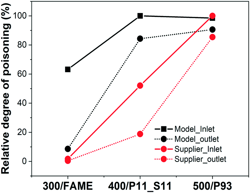 | ||
| Fig. 1 Relative degree of phosphorus poisoning in inlet and outlet of the model and supplier monolith samples. | ||
Fig. 2 displays the BET surface areas of the powder scraped from the model and supplier monolith catalysts. The results evidence that the phosphorus poisoning had a negative effect on the surface area of the DOCs, which can be attributed to a physical effect, i.e., pore blocking. Similar phenomena were also observed by other groups.12,18,30 Correlating the BET results to the ICP results (Table 1) reveals that the catalysts with a larger amount of phosphorus results in a lower surface area. The loss of surface area of Supplier_P93 (ca. 49%) is close to the loss in surface area of DOC_400 and DOC_500, ∼52% and 55%, respectively.
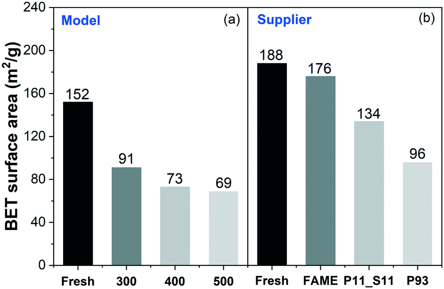 | ||
| Fig. 2 BET surface areas of (a) model and (b) supplier monolith samples. | ||
EDX elemental mapping under SEM observation was conducted to examine the radial distribution of Al, Pd, Pt, and P elements at the inlet of the P-poisoned model and supplier monoliths. Pd and Pt are found to be evenly dispersed on alumina, and for brevity, their mappings are not shown. The mapping images of Al and P are presented in Fig. 3. Note that, for supplier monoliths, prior to measurement, approximately 2 mm at the forefront of the inlets was removed for clear observation. Owing to the thinner and weaker channel wall of the model monoliths in comparison to the supplier monoliths, it was difficult to precisely cut off a small portion of the front end. Thus, the EDX mapping was conducted in the immediate front of the inlet of those monoliths. This explains why the cordierite substrates were contaminated by phosphorus in the model monoliths, as shown in Fig. 3(a)–(c), but not in the supplier monoliths (Fig. 3(d) and (e)). The EDX mapping images are fully consistent with the ICP results, i.e., the higher the concentration of phosphorus, the clearer the observations of phosphorus from SEM-EDX mappings.
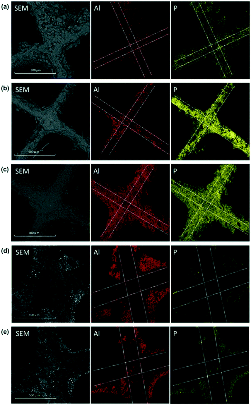 | ||
| Fig. 3 Representative SEM-EDX element mappings of the inlets of (a) DOC_300, (b) DOC_400, (c) DOC_500, (d) Supplier_P11_S11, and (e) Supplier_P93. | ||
The surface phosphorus components of the poisoned monoliths was examined through XPS. Fig. 4(a) displays the normalized spectra of P 2p of the inlets of the model DOC monoliths poisoned at different temperatures. The existence of three kinds of phosphorus species is proposed according to spectral deconvolution, including P2O5 at ∼135.8 eV (denoted P1), PO3− at ∼134.5 eV (denoted P2), and PO43− at ∼133.4 eV (denoted P3).11,31 The deconvolution was conducted using the Shirley model for background subtraction, and fixed peak positions and equal FWHM values were applied. Our earlier work studied the deactivation of Cu/SSZ-13 using the same vapor-phase phosphorus poisoning method, and comparable phosphorus species were found.21 The relative concentrations of the three phosphorus compounds were calculated and are displayed in Fig. 4(b). Note that Fig. 4(b) and also Fig. 4(d) discussed later were not normalized but used a percentage system.
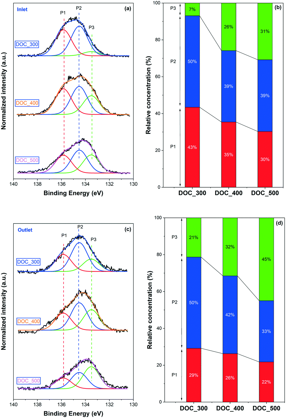 | ||
| Fig. 4 XP P 2p spectra of the model monolith samples poisoned at different temperatures and relative concentrations of the phosphorus species obtained with the deconvolution of the corresponding spectra: (a and b) inlet, (c and d) outlet. | ||
A pronounced trend is found in poisoning temperature with respect to the phosphorus species, i.e., as the poisoning temperature increased, the relative concentrations of P1 (P2O5) and P2 (PO3−) gradually decreased accompanied by an increase in P3 (PO43−). For example, only 7% of PO43− was detected for DOC_300, whereas up to 43% of P2O5 was formed. When the poisoning temperature rose to 500 °C, the former grew significantly, to 31%, while the latter fell to 30%. Note that the decomposition temperatures of phosphoric acid and metaphosphoric acid, i.e., H3PO4 and HPO3, are around 160 °C and 200 °C, respectively. Therefore, it is clear that phosphorus cannot be present on a catalyst surface in the form of acid. Phosphorus can be in the form of P2O5, which is an anhydride of phosphoric acid, where it forms polycyclic dimers that physically block the catalysts. Phosphorus can also interact with the catalyst, e.g., alumina and active sites, to form phosphates/phosphites.18,23 Thus, the above results illustrate that nearly half amount of the phosphorus under poisoning conditions at 300 °C does not chemically react with the catalyst but simply accumulates on the surface of the catalyst in the form of physical coverage (P2O5). Not only does the total phosphorus content increase with an increase in poisoning temperature (ICP results, Table 1), but at the same time, more phosphorus readily reacts with the catalyst in the form of chemical poisoning. According to the Pd, Pt, and P contents presented in Table 1, for example, 0.48 wt% Pd, 0.44 wt% Pt, and 8.1 wt% P were detected at the inlet of DOC_300. A molar ratio of P/(Pd + Pt) close to 40 was obtained with a simple calculation. Assuming that nearly half of the phosphorus is in the form of P2O5, the molar ratio of (PO3− + PO43−)/(Pd + Pt) would be ∼20. This indicates that phosphorus not only interact with Pd and Pt to form Pd(II)/Pt(IV) metaphosphate and phosphates, but also interact with the Al2O3 support possibly forming Al(PO3)3 and/or AlPO4 species.18,32
The XP P 2p spectra and the peak deconvolution of the outlets of the model monoliths are shown in Fig. 4(c) and (d), respectively. In line with the inlet results, a similar trend can be seen in the figure, where higher temperature results in more PO43− species. At the same poisoning temperature, the outlet contains more PO43− and less P2O5 than the inlet, which is similar to the findings for P-poisoned Cu/SSZ-13 monolith catalysts.21 For example, correlating the inlet and outlet phosphorus concentrations of DOC_300, the content of PO43− increases from 7% at the inlet to 21% at the outlet, while that of P2O5 declines from 43% to 29%.
XP P 2p spectra for Supplier_P93 and Supplier_P11_S11 are depicted in Fig. 5(a). Note that only the result for the inlet of Supplier_P11_S11 is shown. The outlet spectrum was close to the baseline, so no clear information was obtained. Three main phosphorus species (i.e., P2O5, PO3−, and PO43−) were identified according to the peak deconvolution. Similar to the P-poisoned model monoliths, the outlet of Supplier_P93 contains a higher concentration of PO43− (58% vs. 45%) and less P2O5 (7% vs. 33%) than the inlet. Considerable similarity is identified between the model monolith poisoned at 500 °C (i.e., DOC_500) and the supplier monoliths, which were poisoned at approximately 450 °C. The phosphorus distribution at the inlet of Supplier_P11_S11 is 41% PO43−, 37% PO3−, and 22% P2O5. It is clear that PO43− is the dominant phosphorus species on Supplier_P11_S11, similar to the case of DOC_500. Based on the results of the ICP (Table 1) and BET (Fig. 2) discussed above, and the XPS results for the DOC_500, we suggest that the lab-scale phosphorus poisoning condition (i.e., vapor-phase) conducted in this study is close to practical applications using a burner with doped biofuels. The same trend in the distribution of phosphorus species at the inlet and outlet is also observed for an engine-aged (biogas) DOC catalyst by Englund and coworkers.11
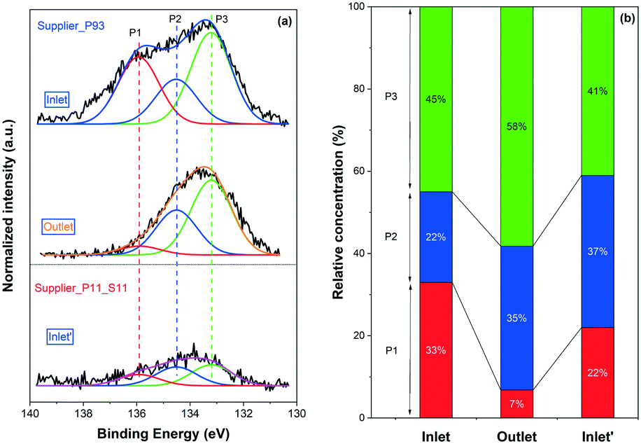 | ||
| Fig. 5 (a) XP P 2p spectra of the Supplier_P93 (inlet and outlet) and Supplier_P11_S11 (inlet′) monolith samples; (b) relative concentrations of the phosphorus species obtained with the deconvolution of the corresponding spectra. | ||
The surface concentrations of phosphorus on both model and supplier monolith samples are displayed in Table 2, based on the XPS experiments. The surface phosphorus atomic percentages (atomic%) were converted to mass percentage (wt%) by assuming that Al, O, Pd, and Pt elements are evenly dispersed on the surface and in the bulk. The phosphorus contents are always higher at the inlets than at the outlets for all samples, and this is in line with the ICP data (Table 1). Note that ICP technology measures the content of each element of bulk catalyst, while XPS only detects the surface concentration of the catalysts (∼5 nm in depth).33,34 Therefore, a comparison of the results obtained from ICP and XPS measurements can give interesting information regarding the distribution of phosphorus. First, the surface phosphorus contents (Table 2) are always greater than that of the bulk content (Table 1) for both model and supplier catalysts. For example, the contents at the inlet of DOC_300 measured with XPS were approximately 14 wt% and measured with ICP were ca. 8 wt%. This gives a strong indication that phosphorus concentration gradient exists in catalyst washcoat layer, where phosphorus (mainly in form of P2O5) tends to accumulate on the surface and partially diffuse into the bulk of washcoat layer.
| Sample | Surface P content (atomic%) | Surface P content (wt%) | P content from ICP (wt%) | |
|---|---|---|---|---|
| DOC_300 | Inlet | 10 | 14 | 8.1 |
| Outlet | 6 | 8 | 1.1 | |
| DOC_400 | Inlet | 12 | 17 | 12.8 |
| Outlet | 6 | 9 | 10.8 | |
| DOC_500 | Inlet | 10 | 14 | 12.6 |
| Outlet | 5 | 7 | 11.6 | |
| Supplier_FAME | Inlet | — | — | 0.16 |
| Outlet | — | — | 0.04 | |
| Supplier_P11_S11 | Inlet | 4 | 5 | 5.0 |
| Outlet | 0.5 | 0.8 | 1.8 | |
| Supplier_P93 | Inlet | 14 | 19 | 9.6 |
| Outlet | 8 | 12 | 8.2 |
The surface phosphorus concentration at the outlets of P-poisoned model catalysts are highly dependent on poisoning temperature. A higher concentration of phosphorus can only be found on the surface of DOC_300 (8 vs. 1 wt%). However, this phenomenon no longer exists when the poisoning temperature is 400 °C or higher. The P inlet/outlet ratios from XPS (surface) and ICP (bulk) of model catalysts are calculated and plotted in Fig. 6(a) to give an intuitive understanding. The surface P inlet/outlet ratios from XPS show a good linear relationship with the poisoning temperature, i.e., the higher the poisoning temperature, the higher the inlet/outlet ratio. However, ICP results show the opposite trend, which is not even linear. The key point is that the temperature of phosphorus poisoning affects not only the bulk content of phosphorus, but also the distribution of phosphorus, both at the inlet and outlet and on the surface and in the bulk of the model monolith samples. Moreover, the comparison results from XPS and ICP of supplier catalysts are plotted in Fig. 6(b). Note that the P inlet/outlet ratios from XPS of Supplier_FAME is not available due to the low concentrations that XPS cannot detect. Interestingly, a linear relationship of the P inlet/outlet ratios from ICP is found for supplier samples. In other words, the higher the phosphorus content, the smaller the ratio of inlet to outlet. Similar phenomenon is also found in the surface P inlet/outlet ratios from XPS results for supplier samples.
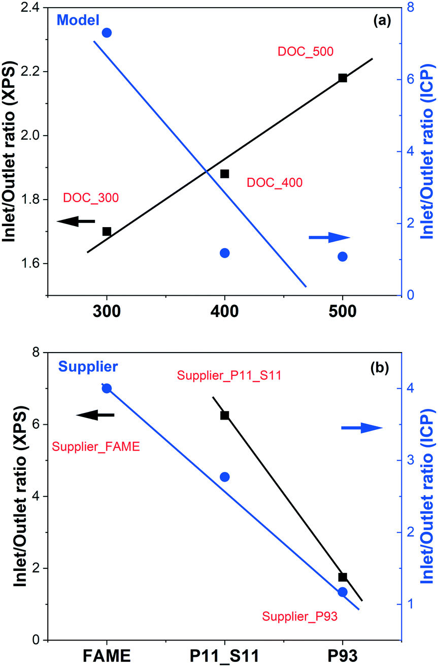 | ||
| Fig. 6 Phosphorus inlet/outlet ratios from XPS (surface) and ICP (bulk) as a function of the phosphorus poisoning temperature of (a) model and (b) supplier monolith samples. | ||
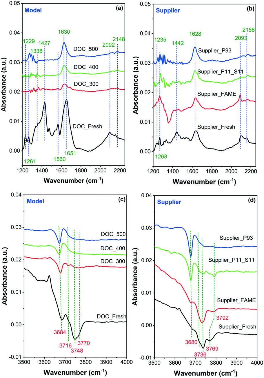
In situ DRIFTS was conducted to observe CO adsorption on the model and supplier catalysts, as displayed in Fig. 7. In addition, the summarized assignment of the vibrations is presented in Table 3. First, the surface properties of the catalysts were examined in the region 1200–2200 cm−1, where the results are shown in Fig. 7(a) for the model catalyst and Fig. 7(b) for the supplier catalyst. Multiple CO adsorption bands can be seen in the figure, and these bands can be divided into two regions: (1) the first region at 1200–1750 cm−1 is due to the formation of different carbonate, bicarbonate, and/or carboxylate species;35,36 (2) the second region at 2000–2200 cm−1 is related to linearly adsorbed CO species.36,37 Briefly, the adsorption bands at ∼1230 and ∼1650 cm−1 are related to the presence of asymmetric bicarbonate species.35 The band at ∼1630 cm−1 is assigned to the symmetric stretching mode of O–C–O of surface bicarbonate, whereas the bands at ∼1440 and 1340 cm−1 are related to the monodentate carbonates species.36,38 Moreover, the band at 1560 cm−1 is likely to be associated with bidentate carbonate species.35,39 Overall, these (bi)carbonates species were mainly formed by the reaction of CO with Pd/Pt oxides on the surface of the catalyst. The high intensity of these signals suggests that the vast majority of Pt and Pd exist in the form of oxides. The band at ∼2150–2160 cm−1 in the second region is attributed to linear carbonyl groups in the Pd2+ complexes, and the one at ∼2090 cm−1 is due to linear CO adsorbed onto metallic or partially oxidized Pt sites and/or on metallic Pd sites.40–42 Accordingly, it can be inferred that a small portion of Pt and Pd exist in the form of metal and isolated ions. The isolated ions may be due to their ion exchange to the acid sites on the surface of the alumina.
 | ||
| Fig. 7 In situ DRIFT spectra recorded during CO adsorption onto (a) and (c) model and (b) and (d) supplier monolith samples. | ||
| FT-IR vibration (cm−1) | Approximate assignment |
|---|---|
| ∼1230 and ∼1650 | Asymmetric bicarbonate |
| ∼1340 and ∼1440 | Monodentate carbonates |
| ∼1560 | Bidentate carbonate |
| ∼2090 | Linear CO on metallic or partially oxidized Pt or metallic Pd |
| ∼2150–2160 | Linear carbonyl in the Pd2+ complexes |
| ∼3680 | AlVI(OH)AlIV |
| ∼3740 | AlVI(OH)AlVI |
| ∼3770 | AlVOH |
It is clear in the model samples that the interaction between CO and the surface of the poisoned catalyst was inhibited to some extent because of phosphorus poisoning, whether chemical (i.e., PO3− and PO43−) or physical (i.e., P2O5) (Fig. 7(a)). The bands at ∼1230, 1340, 1440, and 1560 cm−1 had mostly disappeared, whereas the bands at ∼1630, 2092, and 2150 cm−1 had been considerably weakened. A similar phenomenon was also observed in the supplier catalysts (Fig. 7(b)). Note that some other changes occurred after the aging/poisoning with FAME. For example, one negative band was found at ∼1350 cm−1, which is possibly due to the presence of sulfur species.
The DRIFTS spectra of CO adsorption onto the model and supplier samples in the 3500–4000 cm−1 region are displayed in Fig. 7(c) and (d), respectively. It is known that the IR bands in this region are attributed to surface hydroxyl groups,43,44e.g., ∼3680, 3740, and 3770 cm−1. The band at ∼3680 cm−1 is assigned to the bridging OH groups AlVI(OH)AlIV bonded to octahedral and tetrahedral aluminum, whereas the ∼3740 cm−1 band is related to AlVI(OH)AlVI bonded to octahedral aluminum.45 A terminal OH group (AlVOH) was also observed, i.e., the band at ∼3770 cm−1.45 Only the OH band at ∼3680 cm−1, i.e., AlVI(OH)AlIV remained after phosphorus poisoning. This suggests that the majority of the OH groups had been contaminated by phosphorus. This finding is consistent with the data from ICP and XPS measurements, i.e., that phosphorus can also react with the support material (Al2O3), possibly forming Al(PO3)3 and/or AlPO4 species.
NO-TPD was conducted to investigate the influence of phosphorus on the NO adsorption ability of the catalysts, which can possibly be related to NO conversion (section 3.2). The results are shown in Fig. 8. Note that NO, NO2, and N2O concentrations were all followed by the MKS detector during the TPD experiments. It was found that NO was the main desorption product with a small amount of NO2, while no N2O was detected at all in any of the samples. Therefore, for the sake of brevity, the total NOx concentration (NO + NO2) is displayed in the figure.
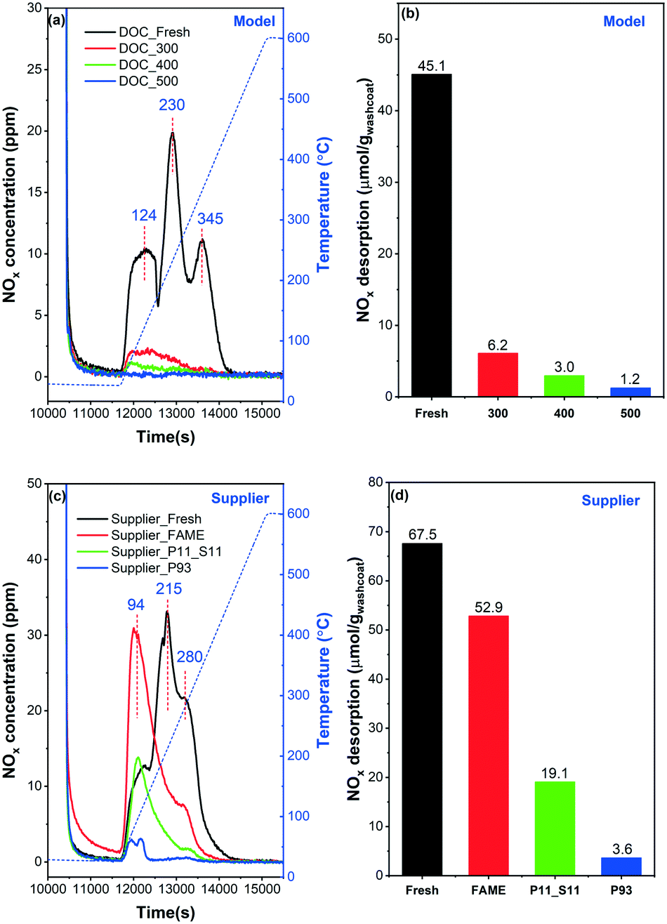 | ||
| Fig. 8 NO-TPD profiles and the NOx desorption amounts calculated from the corresponding spectra: (a) and (b) model catalyst, (c) and (d) supplier catalyst. | ||
Three main NOx desorption features can be found for DOC_Fresh in the 50–400 °C temperature range (Fig. 8(a)). These peaks are located in the low (∼120 °C), moderate (∼230 °C) and high (∼350 °C) temperature regions, respectively. This indicates that three different types of sites or species can be associated with NO adsorption, which is also in line with the study by Anguita and coworkers.12 The low-temp peak (∼120 °C) can be assigned to the weakly adsorbed NO and the other to more stable NO-adsorbed species due to the formation of nitrites and nitrates species.46,47 Only small desorption features of NOx were detected for the poisoned catalysts, in the low temperature region. The total amounts of NOx desorption (equal to storage) were calculated and are displayed in Fig. 8(b). The NOx storage decreases with the increase of poisoning temperature. For example, the NOx storage for DOC_300 and DOC_500 declines from 6.2 to 1.2 μmol gwashcoat−1. Note that, DOC_400 and DOC_500 have similar total phosphorus contents (Table 1), and the main reason for the difference in NOx storage (3.0 vs. 1.2 μmol gwashcoat−1) can be assigned to the difference in phosphorus species, as shown in the XPS data (Fig. 4).
Some noteworthy phenomena can be observed for supplier catalysts in Fig. 8(c). First, similar to the model catalysts, three desorption peaks were detected in Supplier_Fresh. This suggests that there are also three types of sites available for NOx adsorption, as discussed above. However, the desorption peaks are shifted to lower values for the supplier catalyst (94, 215 and 280 °C), compared to the model catalyst (124, 230, 345 °C). This shift might/could be due to differences in catalysts composition, as shown by the ICP results (lower Pd content in the supplier catalysts). In addition, the synthesis method may differ for the model and supplier catalysts (unknown synthesis method for the supplier samples), and this can also have an effect on the desorption temperatures. The distribution of sites changed significantly upon ‘FAME’ treatment (i.e., at ∼440–455 °C for 140–178 hours), according to the shift in NO desorption temperature (black and red lines). A dramatic increase in the low-temperature region (∼100 °C) is accompanied by a significant decrease in the moderate/high temperature area (∼200–400 °C). With the addition of phosphorus, i.e., Supplier_P11_S11 and Supplier_P93, the adsorption capacity of NOx decreases significantly. Briefly, the greater the phosphorus content, the less the NO storage. Fig. 8(d) summarizes the NOx desorption amounts (μmol gwashcoat−1) for supplier catalysts. It is found that the NOx storage of Supplier_FAME (52.9 μmol gwashcoat−1) is slightly lower than the storage capacity of Supplier_Fresh (67.5 μmol gwashcoat−1). This is likely due to the presence of small amounts of phosphorus and sulfur (Table 1). The amount of NO desorbed decreases to 19.1 and 3.6 μmol gwashcoat−1 for Supplier_P11_S11 and Supplier_P93 with the poisoning of phosphorus. Note that Supplier_P93 and DOC_400 show similar amounts of NOx desorption.
H2-TPR experiments were conducted on model and supplier catalysts to study the effect of phosphorus poisoning on the redox capability of the active sites, and results are shown in Fig. 9. Note that the samples were first purged at 25 °C in 0.2% H2/Ar for 10 min until the signal was constant. After that, the samples were heated to 800 °C in the same gas mixture. We observed some H2 consumption in the beginning of the H2 addition to the gas mixture during the purge stage (not shown). However, it should be noted that some of the H2 consumption at room temperature could be related to the low flow giving a slow step response when adding a new gas. The TPR profiles of the model catalysts are displayed in Fig. 9(a). DOC_Fresh (black line) only presented one minor signal related to H2 consumption in the examined temperature interval (25–800 °C), centered at ∼290 °C, and attributable to oxidic platinum particles in strong interaction with the support.43 This phenomenon indicates that the majority of the Pd and/or Pt oxide particles, as well as chemisorbed oxygen, were reduced when H2 was introduced at 25 °C and not during the temperature ramp, which is in line with the literature.48 According to previous studies,48,49 a negative band around 50–100 °C attributed to the decomposition of Pd hydride (PdHx) phase can typically be found on Pd-supported catalysts due to the low dispersion of Pd particles in the catalysts, in other words, the presence of a possible palladium-rich phase. However, this was not the case in our experiments where a distinct H2 desorption peak was only observed at 470 °C, which is much higher than the typical temperature for Pd hydride decomposition (<100 °C). Accordingly, it is suggested that the presence of Pt may greatly increase the thermal stability of Pd hydride. Guerrero et al.49 have recently found similar high-temperature decomposition profiles for Pd hydride (at 381 and 616 °C). The PdHx should be formed at room temperature, i.e., 25 °C, during the purge stage in 0.2% H2/Ar.
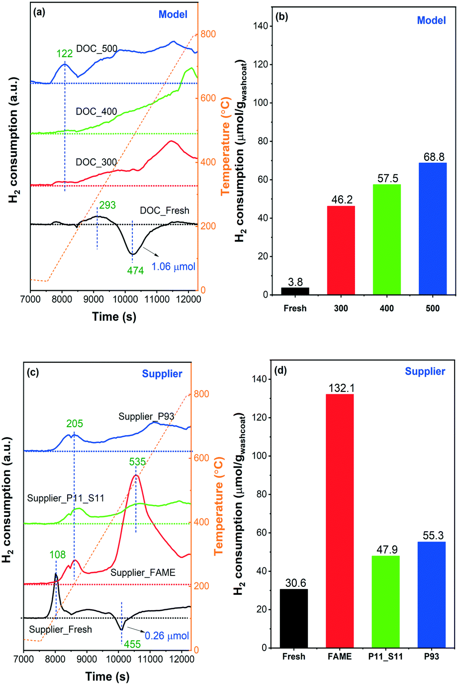 | ||
| Fig. 9 H2-TPR curves and the H2 consumption amounts calculated from the corresponding spectra: (a) and (b) model, (c) and (d) supplier catalysts. The samples were pretreated in flowing Ar at 150 °C for 30 min and then cooled to ambient temperature in Ar prior to TPR. TPR was conducted from 25 to 800 °C at 10 °C min−1 in 0.2% H2/Ar. | ||
No negative features, i.e. hydrogen release, were found after phosphorus poisoning regardless of the poisoning temperature, i.e., no Pd hydride species were formed in the poisoned catalyst. A broad H2 consumption region was found in all three poisoned catalysts, initially from ∼100 to 800 °C. For an intuitive comparison, the amount of H2 consumption (μmol gwashcoat−1) was calculated and is displayed in Fig. 9(b). As the poisoning temperature increases, the consumption of H2 also increases. A significant increase in H2 consumption is found for the poisoned catalysts compared to DOC_Fresh. Thus, we can infer that the reduction temperatures of Pd and Pt particles increased significantly due to the presence of phosphorus,12 where the reduction temperature shifted from less than 25 °C to the temperature interval at which we performed TPR (25–800 °C). As the total phosphorus contents between DOC_400 and DOC_500 are similar (Table 1) and considering the XPS data (Fig. 4), the increase in H2 consumption suggests that PO43− had a greater influence on the active center than P2O5, which is also in line with the NO-TPD results (Fig. 8). We found that the poisoned catalysts consumed H2 even at 800 °C, where H2 concentration did not return to the inlet value. The high-temperature consumption of H2 might be attributed to the reduction of surface hydroxyl groups on alumina,50 However, since the fresh model catalyst does not consume H2 at high temperature this attribution is rather unlikely. It is also found that the samples with phosphorus present have larger high temperature consumption, which is especially clear for the model catalyst (Fig. 9a). Phosphorus could easily react with alumina to form AlPO4 on the surface,24 which possibly weaken the Al–O–Al by having Al–O–Al–O–P and make the reduction of O–Al–O easier. Thus, a possible attribution to the high temperature hydrogen consumption could be from the reduction of alumina in the presence of phosphorus.
The TPR profile of Supplier_Fresh catalyst showed a significant difference from DOC_Fresh with a higher H2 consumption peak/region (Fig. 9(c)). The reduction temperature of Pd/Pt oxide particles highly depends on the size and dispersion.50 Larger size and poorer dispersion result in a lower reduction temperature.50 Therefore, the results suggest that the dispersion of Pd/Pt sites is better in the supplier catalysts than in the model catalysts. One sharp peak at 108 °C can be assigned to the reduction of small-size Pd/Pt oxide clusters, whereas the H2 consumption at a higher temperature (>200 °C) is due to the combined effects of strong interaction of PtOx particles with the support and possible reduction of surface hydroxyl groups on alumina.43,50,51 Meanwhile, a negative peak was detected at ∼450 °C owing to the desorption of H2 that occurred from the decomposition of Pd hydride, which is consistent with findings for DOC_Fresh. As inserted in Fig. 9(a) and (c), only 0.26 μmol gwashcoat−1 of H2 desorption for Supplier_Fresh, whereas, it is 1.06 μmol gwashcoat−1 for DOC_Fresh. The significantly lower H2 desorption of Supplier_Fresh can be attributed to the lower content of Pd (Table 1) together with better dispersion. The sharp H2 consumption peak at 108 °C and the negative feature at 455 °C for Supplier_FAME disappeared simultaneously, which could be due to poisoning by phosphorus and likely also by sulfur (Table 1). One significant H2 consumption peak at 535 °C was observed, and it is not likely that the peak was caused by the reduction of Pd/Pt particles, according to the other three TPR profiles. Instead, it could be due to the presence of sulfur (∼0.4 wt%). It is well known that H2 can react with sulfate species, and thereby regenerate noble metal catalysts. This is a common procedure for the regeneration of NOx storage and reduction catalysts from sulfur.13,52 Since the content of sulfur in the other three supplier catalysts was negligible (<0.02 wt%), no such feature could be identified.
It is also found that the higher the content of phosphorus (Supplier_P93 versus Supplier_P11_S11), the higher the consumption of H2, as shown in Fig. 9(d). In comparison with the model catalyst (e.g., DOC_500), the phosphorus-poisoned supplier catalyst (e.g., Supplier_P93) shows a higher starting H2 reduction temperature, which is 122 °C on the former and 205 °C on the latter. This is in line with the TPR profiles of their corresponding fresh catalysts and is likely due to differences in the dispersion of Pd/Pt sites.
3.2. Catalytic activity
Catalytic tests for ‘pure’ CO oxidation, NO oxidation, and mixed-gas (CO, NO, C3H6, and C3H8) oxidation were performed in oxygen excess (10% O2) and in the presence of steam (5% H2O) at a GHSV of 22200 h−1 to mimic the realistic conditions in which these catalysts must operate.
The catalytic performances for the model and supplier catalysts towards ‘pure’ CO oxidation are presented in the first panels of Fig. 10(a) and (b), respectively, where the solid lines show heating, and short dotted lines show the cooling process. The temperature used for plotting these curves was the one in the middle of the monoliths. The samples were first cooled from 500 °C to 100 °C, maintained at 100 °C for 15 min, and then heated to 500 °C again. Note that the conversion/change in gas composition was measured during heating and cooling, i.e. not at steady state. As seen in the figures, the catalyst temperature (used in the conversion figures) at the turning point, i.e. 100 °C in the gas phase, is slightly different in some cases for some samples. Therefore, the conversion can also differ. This temperature difference is mainly due to that it takes some time to cool the monolith; after the cooling process, the temperature is kept at 100 °C for 15 min before the heating process is started. Consequently, the sample temperature just after the cooling step and just before the heating is started (15 min later), may differ to some extent.
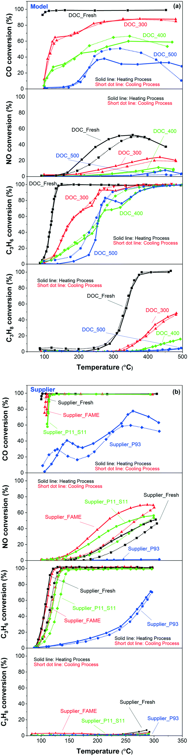 | ||
| Fig. 10 CO (first panels), NO (second panels), C3H6 (third panels), C3H8 (fourth panels) oxidation for the (a) model and (b) supplier monolith samples. The reaction feed contains 100 ppm CO, or 1000 ppm NO, or 100 ppm C3H6, or 100 ppm C3H8, 10% O2, 5% H2O, balanced with Ar at a GHSV of 22100 h−1. | ||
First, Fig. 10(a) shows a clear trend in catalytic activity for the model catalysts: as the poisoning temperature increases, the catalytic activity of CO oxidation gradually decreases. All the phosphorus-poisoned samples show a significant increase in light-off temperature, and furthermore, full conversion could not be reached even at 500 °C. This effect is especially pronounced for the samples poisoned at 400 and 500 °C (DOC_400 and DOC_500) and is due to fouling or masking of the active sites by phosphorus. The performance of DOC_400 was expected to be inferior to that of DOC_300 due to the higher content of phosphorus and the smaller surface area for DOC_400 determined using ICP and BET measurements (Table 1 and Fig. 2). Interestingly, DOC_400 and DOC_500 had similar phosphorus content (inlet: 12.8 and 12.6 wt%; outlet: 10.8 and 11.6 wt%) and surface area (73 and 69 m2 g−1) but showed different performance towards CO oxidation. DOC_500 was more deactivated than DOC_400. The XPS spectra (Fig. 4) and H2-TPR profiles (Fig. 9) provided important insights into this phenomenon. These results clearly show that the distribution of phosphorus species (e.g., P2O5 and PO43−) was different for DOC_400 and DOC_500. Thus, the redox capacity of the active center was affected to varying degrees. Fig. 4 shows that the concentration of P3 (i.e., PO43−) in DOC_500 was higher than that of DOC_400 at both the inlet and the outlet. Therefore, we suggest that PO43− has a more severe impact on catalytic activity than does P2O5.
Fig. 10(b) (first panel) shows that the order of reactivity towards CO oxidation for supplier catalysts is: Supplier_Fresh > Supplier_FAME > Supplier_P11_S11 > Supplier_P93. This is consistent with the ICP and BET results in terms of phosphorus content and surface area (Table 1 and Fig. 2). In addition, the performance of Supplier_P93 is similar to that of DOC_400 and DOC_500, suggesting that vapor-phase phosphorus poisoning can substantially simulate actual poisoning conditions.
The light-off curves of NO oxidation are plotted in the second panels of Fig. 10(a) and (b), for model and supplier catalysts, respectively. Higher temperature poisoning leads to a more severe loss in activity in the model catalysts, which is in line with the NO-TPD results (Fig. 8) and CO oxidation. NO oxidation seems to be more significantly affected by phosphorus poisoning than CO oxidation, where DOC_500 is barely active. Some interesting phenomena emerges pertaining to the supplier catalysts. The order of NO oxidation reactivity is somewhat different to CO oxidation: Supplier_FAME > Supplier_P11_S11 > Supplier_Fresh > Supplier_P93. This was unexpected. One possible reason can be proposed according to the NO-TPD findings (Fig. 8), where a significant increase in NO desorption took place in the low-temperature region (∼100 °C): the nature of the Pd/Pt sites was modified during the FAME aging condition (∼440–455 °C for 140–178 h in FAME exhaust), and NO oxidation was sensitive to this modification in comparison to CO. It is well-known that larger Pt particles have higher activity per site, which is proposed to be because they are more resistant to platinum oxide formation.53 Therefore, the improved NO oxidation performance on Supplier_FAME is possibly due to that some sintering occurred during the FAME aging/poisoning. Similar to DOC_500, Supplier_P93 was completely deactivated after phosphorus poisoning.
The lower two panels in Fig. 10(a) and (b) present the light-off curves of C3H6 and C3H8, respectively. Similar phenomenon was obtained as for CO oxidation. Clearly, for model catalysts, the higher the poisoning temperature, the lower the activity and for supplier samples, the higher the phosphorus content, the lower the activity. The reasons are the same as discussed earlier for CO oxidation.
Fig. 11 displays the light-off curves for different components (i.e., CO, NO, C3H6, and C3H8) in mixed gas. The trend was similar for CO and NO oxidation as the results of the ‘pure’ case shown in Fig. 10. A slight decrease in the activity of the fresh catalysts towards CO and NO oxidation due to the presence of other reactant gases was also observed. Some negative conversion values were found in the temperature region of 300–400 °C of CO oxidation. These negative values were originated to the CO production by the incomplete combustion of the hydrocarbons (i.e., C3H6 and/or C3H8). Model and supplier catalysts showed a similar order of activity for C3H6 and C3H8 oxidation as for CO oxidation. DOC_400 and DOC_500 showed similar activity towards C3H6 oxidation (third panel of Fig. 11(a)). However, examining also the CO conversion (first panel of Fig. 11(a)), it can be seen that more CO were produced from the incomplete combustion of C3H6 for the DOC_500 catalyst.
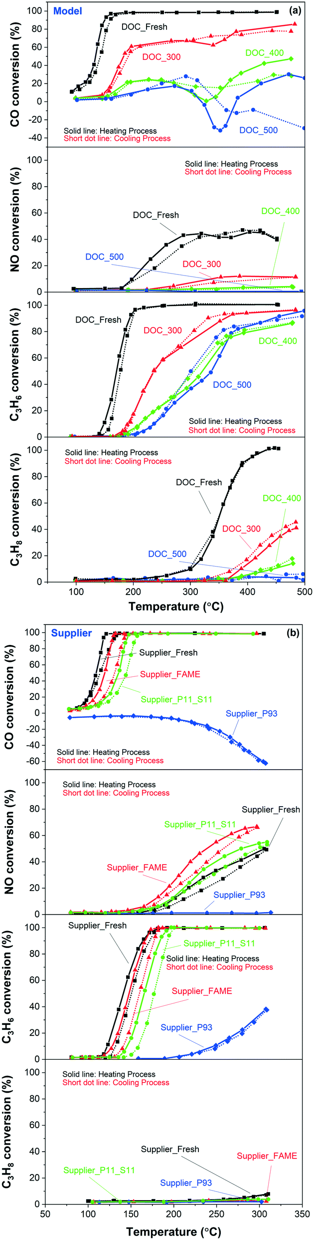 | ||
| Fig. 11 CO (first panels), NO (second panels), C3H6 (third panels) and C3H8 (fourth panels) oxidation for the (a) model and (b) supplier monolith samples in mixed gases. The reaction feed contains 100 ppm CO, 1000 ppm NO, 100 ppm C3H6, 100 ppm C3H8, 10% O2, 5% H2O balanced with Ar at a GHSV of 22100 h−1. | ||
4. Conclusions
The deactivation of diesel oxidation catalysts, i.e., Pd–Pt/Al2O3, with phosphorus was studied using model and supplier catalysts. The phosphorus poisoning was conducted differently on model and supplier catalysts. The model catalysts were exposed to H3PO4 vapor-containing flows (100 ppm H3PO4, 5% H2O, 8% O2 and Ar) for a certain time at different temperatures (300, 400 and 500 °C). The supplier catalysts were aged/poisoned with a diesel burner using non-doped and doped biodiesel (EN14214) at two different phosphorus concentrations (11 and 93 ppm). The fresh and poisoned catalysts were used to study oxidation performance, i.e., ‘pure’ CO/NO/C3H6/C3H8 oxidation and mixed-gas (CO, NO, C3H6 and C3H8) oxidation. Different techniques, including ICP, BET, SEM-EDX, XPS, DRIFTS, NO-TPD, and H2-TPR, were used to investigate the deactivation mechanism upon phosphorus poisoning.The obtained results from model catalysts suggest that the temperature of phosphorus poisoning not only affects the overall content of phosphorus but also the dispersion of phosphorus, regardless at the inlet or outlet, on the surface, or in the bulk of the monolith catalyst. Three main phosphorus species, i.e., phosphorus oxide (P2O5), metaphosphate (PO3−), and phosphate (PO43−), were identified in the poisoned catalysts (both model and supplier catalysts). The distribution of these phosphorus species on model catalysts was highly dependent on poisoning temperature, i.e., a higher temperature resulted in a higher concentration of PO43− and a lower concentration of P2O5. It was also found that the outlets contained more PO43− and less P2O5 than the inlets in both the model and supplier catalysts. Due to the similarity between DOC_400/DOC_500 and Supplier_P93 (aging temperature around 450 °C), it is suggested that the vapor-phase phosphorus poisoning applied in this study can substantially simulate actual poisoning conditions. Both active sites and surface OH groups on model and supplier catalysts were affected by phosphorus poisoning. It was also found that PO43− had a greater influence on active sites than P2O5. Overall, the deactivation of DOCs in the presence of phosphorus can be attributed both to physical, e.g., surface area decline, and chemical deactivation, e.g., the formation of Pd(II), Pt(IV) metaphosphate/phosphate, and Al(PO3)3/AlPO4 species.
In addition, by correlating the features of poisoned model catalysts by vapor phase poisoning to the poisoned supplier catalysts by diesel burner, we conclude that the vapor-phase phosphorus poisoning could be further optimized and become a practical and cost efficient approach to simulate an accelerated aging/poisoning process.
Conflicts of interest
There are no conflicts to declare.Acknowledgements
This study was performed at the Division of Chemical Engineering and the Competence Centre for Catalysis, Chalmers University of Technology in collaboration with KTH, Volvo AB, Scania CV AB and Umicore. The authors gratefully acknowledge financial support from the Swedish Research Council (642-2014-5733), Swedish Energy Agency (FFI-project no. 37178-1) and the Area of Advance Transport at Chalmers University of Technology. We would also like to acknowledge Ton VW Janssens and Henrik Malm at Umicore for arrangement and help with the burner aging.References
- O. Raaschou-Nielsen, R. Beelen, M. Wang, G. Hoek, Z. J. Andersen, B. Hoffmann, M. Stafoggia, E. Samoli, G. Weinmayr, K. Dimakopoulou, M. Nieuwenhuijsen, W. W. Xun, P. Fischer, K. T. Eriksen, M. Sørensen, A. Tjønneland, F. Ricceri, K. de Hoogh, T. Key, M. Eeftens, P. H. Peeters, H. B. Bueno-de-Mesquita, K. Meliefste, B. Oftedal, P. E. Schwarze, P. Nafstad, C. Galassi, E. Migliore, A. Ranzi, G. Cesaroni, C. Badaloni, F. Forastiere, J. Penell, U. De Faire, M. Korek, N. Pedersen, C. G. Östenson, G. Pershagen, L. Fratiglioni, H. Concin, G. Nagel, A. Jaensch, A. Ineichen, A. Naccarati, M. Katsoulis, A. Trichpoulou, M. Keuken, A. Jedynska, I. M. Kooter, J. Kukkonen, B. Brunekreef, R. S. Sokhi, K. Katsouyanni and P. Vineis, Particulate matter air pollution components and risk for lung cancer, Environ. Int., 2016, 87, 66–73 CrossRef CAS PubMed.
- R. Matarrese, E. Aneggi, L. Castoldi, J. Llorca, A. Trovarelli and L. Lietti, Simultaneous removal of soot and NOx over K- and Ba-doped ruthenium supported catalysts, Catal. Today, 2016, 267, 119–129 CrossRef CAS.
- S. Zhao, F. Chen, S. Duan, B. Shao, T. Li, H. Tang, Q. Lin, J. Zhang, L. Li, J. Huang, N. Bion, W. Liu, H. Sun, A.-Q. Wang, M. Haruta, B. Qiao, J. Li, J. Liu and T. Zhang, Remarkable active-site dependent H2O promoting effect in CO oxidation, Nat. Commun., 2019, 10, 3824 CrossRef PubMed.
- C. H. Wu, C. Liu, D. Su, H. L. Xin, H.-T. Fang, B. Eren, S. Zhang, C. B. Murray and M. B. Salmeron, Bimetallic synergy in cobalt–palladium nanocatalysts for CO oxidation, Nat. Catal., 2019, 2, 78–85 CrossRef CAS.
- A. Y. Wang, Y. L. Wang, E. D. Walter, N. M. Washton, Y. L. Guo, G. Z. Lu, C. H. F. Peden and F. Gao, NH3-SCR on Cu, Fe and Cu plus Fe exchanged beta and SSZ-13 catalysts: Hydrothermal aging and propylene poisoning effects, Catal. Today, 2019, 320, 91–99 CrossRef CAS.
- J. Dou, Y. Tang, L. Nie, C. M. Andolina, X. Zhang, S. House, Y. Li, J. Yang and F. Tao, Complete Oxidation of Methane on Co3O4/CeO2 Nanocomposite: A Synergic Effect, Catal. Today, 2018, 311, 48–55 CrossRef CAS.
- A. Wang, B. Lin, H. Zhang, M. H. Engelhard, Y. Guo, G. Lu, C. H. Peden and F. Gao, Ambient temperature NO oxidation over Cr-based amorphous mixed oxide catalysts: effects from the second oxide components, Catal. Sci. Technol., 2017, 7, 2362–2370 RSC.
- J. Lee, J. R. Theis and E. A. Kyriakidou, Vehicle emissions trapping materials: Successes, challenges, and the path forward, Appl. Catal., B, 2019, 243, 397–414 CrossRef CAS.
- A. Wang, Y. Chen, E. D. Walter, N. M. Washton, D. Mei, T. Varga, Y. Wang, J. Szanyi, Y. Wang, C. H. F. Peden and F. Gao, Unraveling the mysterious failure of Cu/SAPO-34 selective catalytic reduction catalysts, Nat. Commun., 2019, 10, 1137 CrossRef PubMed.
- M. Shelef and G. W. Graham, Why Rhodium in Automotive Three-Way Catalysts?, Catal. Rev.: Sci. Eng., 1994, 36, 433–457 CrossRef CAS.
- J. Englund, K. Xie, S. Dahlin, A. Schaefer, D. Jing, S. Shwan, L. Andersson, P.-A. Carlsson, L. J. Pettersson and M. Skoglundh, Deactivation of a Pd/Pt Bimetallic Oxidation Catalyst Used in a Biogas-Powered Euro VI Heavy-Duty Engine Installation, Catalysts, 2019, 9, 1014 CrossRef CAS.
- P. Anguita, J. M. García-Vargas, F. Gaillard, E. Iojoiu, S. Gil and A. Giroir-Fendler, Effect of Na, K, Ca and P-impurities on diesel oxidation catalysts (DOCs), Chem. Eng. J., 2018, 352, 333–342 CrossRef CAS.
- J. E. De Abreu Goes, A. Kristoffersson and L. Olsson, Sulfur Poisoning Effects on Modern Lean NOx Trap Catalysts Components, Catalysts, 2019, 9, 492 CrossRef CAS.
- B. Pereda-Ayo, J. R. González-Velasco, R. Burch, C. Hardacre and S. Chansai, Regeneration mechanism of a Lean NOx Trap (LNT) catalyst in the presence of NO investigated using isotope labelling techniques, J. Catal., 2012, 285, 177–186 CrossRef CAS.
- A. Y. Wang and L. Olsson, The impact of automotive catalysis on the United Nations sustainable development goals, Nat. Catal., 2019, 2, 566–570 CrossRef.
- S. J. Eaton, K. Nguyen and B. G. Bunting, Deactivation of Diesel Oxidation Catalysts by Oil-Derived Phosphorus, SAE International, 2006 Search PubMed.
- A. Väliheikki, T. Kolli, M. Honkanen, O. Heikkinen, M. Kärkkäinen, K. Kallinen, M. Huuhtanen, M. Vippola, J. Lahtinen and R. L. Keiski, The Impact of Sulphur, Phosphorus and their Co-effect on Pt/SiO2–ZrO2 Diesel Oxidation Catalysts, Top. Catal., 2017, 60, 307–311 CrossRef.
- S. J. Eaton, B. G. Bunting, T. J. Toops and K. Nguyen, The Roles of Phosphorus and Soot on the Deactivation of Diesel Oxidation Catalysts, SAE International, 2009 Search PubMed.
- A. Valiheikki, M. Karkkainen, M. Honkanen, O. Heikkinen, T. Kolli, K. Kallinen, M. Huuhtanen, M. Vippola, J. Lahtinen and R. L. Keiski, Deactivation of Pt/SiO2-ZrO2 diesel oxidation catalysts by sulphur, phosphorus and their combinations, Appl. Catal., B, 2017, 218, 409–419 CrossRef CAS.
- S. Dahlin, M. Nilsson, D. Bäckström, S. L. Bergman, E. Bengtsson, S. L. Bernasek and L. J. Pettersson, Multivariate analysis of the effect of biodiesel-derived contaminants on V2O5-WO3/TiO2 SCR catalysts, Appl. Catal., B, 2016, 183, 377–385 CrossRef CAS.
- K. Xie, A. Wang, J. Woo, A. Kumar, K. Kamasamudram and L. Olsson, Deactivation of Cu-SSZ-13 SCR Catalysts by Vapor-Phase Phosphorus Exposure, Appl. Catal., B, 2019, 256, 117815 CrossRef CAS.
- H. Zhao, Y. Zhao, M. Liu, X. Li, Y. Ma, X. Yong, H. Chen and Y. Li, Phosphorus modification to improve the hydrothermal stability of a Cu-SSZ-13 catalyst for selective reduction of NOx with NH3, Appl. Catal., B, 2019, 252, 230–239 CrossRef CAS.
- V. Kröger, M. Hietikko, D. Angove, D. French, U. Lassi, A. Suopanki, R. Laitinen and R. L. Keiski, Effect of phosphorus poisoning on catalytic activity of diesel exhaust gas catalyst components containing oxide and Pt, Top. Catal., 2007, 42, 409–413 CrossRef.
- A. Wang, K. Xie, D. Bernin, A. Kumar, K. Kamasamudram and L. Olsson, Deactivation mechanism of Cu active sites in Cu/SSZ-13 Phosphorus poisoning and the effect of hydrothermal aging, Appl. Catal., B, 2020, 269, 118781 CrossRef CAS.
- V. Kröger, T. Kanerva, U. Lassi, K. Rahkamaa-Tolonen, M. Vippola and R. L. Keiski, Characterization of phosphorus poisoning on diesel exhaust gas catalyst components containing oxide and Pt, Top. Catal., 2007, 45, 153–157 CrossRef.
- S. Dahlin, J. Englund, H. Malm, M. Feigel, B. Westerberg, F. Regali, M. Skoglundh and L. J. Pettersson, Effect of biofuel- and lube oil-originated sulfur and phosphorus on the performance of Cu-SSZ-13 and V2O5-WO3/TiO2 SCR catalysts, Catal. Today, 2020 Search PubMed , in press.
- X. Auvray and L. Olsson, Stability and activity of Pd-, Pt-and Pd–Pt catalysts supported on alumina for NO oxidation, Appl. Catal., B, 2015, 168, 342–352 CrossRef.
- Y. Jangjou, Q. Do, Y. T. Gu, L. G. Lim, H. Sun, D. Wang, A. Kumar, J. H. Li, L. C. Grabow and W. S. Epling, Nature of Cu Active Centers in Cu-SSZ-13 and Their Responses to SO2 Exposure, ACS Catal., 2018, 8, 1325–1337 CrossRef CAS.
- K. Wijayanti, K. Leistner, S. Chand, A. Kumar, K. Kamasamudram, N. W. Currier, A. Yezerets and L. Olsson, Deactivation of Cu-SSZ-13 by SO2 exposure under SCR conditions, Catal. Sci. Technol., 2016, 6, 2565–2579 RSC.
- V. Kröger, U. Lassi, K. Kynkäänniemi, A. Suopanki and R. L. Keiski, Methodology development for laboratory-scale exhaust gas catalyst studies on phosphorus poisoning, Chem. Eng. J., 2006, 120, 113–118 CrossRef.
- T. Liu, X. Ma, D. Liu, S. Hao, G. Du, Y. Ma, A. M. Asiri, X. Sun and L. Chen, Mn Doping of CoP Nanosheets Array: An Efficient Electrocatalyst for Hydrogen Evolution Reaction with Enhanced Activity at All pH Values, ACS Catal., 2017, 7, 98–102 CrossRef CAS.
- F. Cabello Galisteo, C. Larese, R. Mariscal, M. López Granados, J. L. G. Fierro, R. Fernández-Ruiz and M. Furió, Deactivation on vehicle-aged diesel oxidation catalysts, Top. Catal., 2004, 30, 451–456 CrossRef.
- J. B. Gilbert, M. F. Rubner and R. E. Cohen, Depth-profiling X-ray photoelectron spectroscopy (XPS) analysis of interlayer diffusion in polyelectrolyte multilayers, Proc. Natl. Acad. Sci. U. S. A., 2013, 110, 6651–6656 CrossRef CAS.
- P. Bruno, M. Caselli, M. L. Curri, P. Favia, R. Lamendola, A. Mangone, A. Traini and C. Laganara, XPS, ICP and DPASV analysis of medieval pottery — Statistical multivariate treatment of data, Fresenius' J. Anal. Chem., 1994, 350, 168–177 CrossRef CAS.
- A. Kaftan, M. Kusche, M. Laurin, P. Wasserscheid and J. Libuda, KOH-promoted Pt/Al2O3 catalysts for water gas shift and methanol steam reforming: An operando DRIFTS-MS study, Appl. Catal., B, 2017, 201, 169–181 CrossRef CAS.
- A. A. El-Moemen, A. M. Abdel-Mageed, J. Bansmann, M. Parlinska-Wojtan, R. J. Behm and G. Kučerová, Deactivation of Au/CeO2 catalysts during CO oxidation: Influence of pretreatment and reaction conditions, J. Catal., 2016, 341, 160–179 CrossRef.
- Q. Zhang, L. Lv, J. Zhu, X. Wang, J. Wang and M. Shen, The effect of CO on NO reduction over Pt/Pd-based NSR catalysts at low temperature, Catal. Sci. Technol., 2013, 3, 1069–1077 RSC.
- M. A. Newton, D. Ferri, G. Smolentsev, V. Marchionni and M. Nachtegaal, Room-temperature carbon monoxide oxidation by oxygen over Pt/Al2O3 mediated by reactive platinum carbonates, Nat. Commun., 2015, 6, 8675 CrossRef CAS.
- I. Tankov, W. Cassinelli, J. Bueno, K. Arishtirova and S. Damyanova, DRIFTS study of CO adsorption on praseodymium modified Pt/Al2O3, Appl. Surf. Sci., 2012, 259, 831–839 CrossRef CAS.
- Y. Zhang, Y. Cai, Y. Guo, H. Wang, L. Wang, Y. Lou, Y. Guo, G. Lu and Y. Wang, The effects of the Pd chemical state on the activity of Pd/Al2O3 catalysts in CO oxidation, Catal. Sci. Technol., 2014, 4, 3973–3980 RSC.
- H. Wang, X.-K. Gu, X. Zheng, H. Pan, J. Zhu, S. Chen, L. Cao, W.-X. Li and J. Lu, Disentangling the size-dependent geometric and electronic effects of palladium nanocatalysts beyond selectivity, Sci. Adv., 2019, 5, eaat6413 CrossRef.
- H. Feng, J. Lu, P. C. Stair and J. W. Elam, Alumina Over-coating on Pd Nanoparticle Catalysts by Atomic Layer Deposition: Enhanced Stability and Reactivity, Catal. Lett., 2011, 141, 512–517 CrossRef CAS.
- Z. Say, E. I. Vovk, V. I. Bukhtiyarov and E. Ozensoy, Influence of ceria on the NOx reduction performance of NOx storage reduction catalysts, Appl. Catal., B, 2013, 142–143, 89–100 CrossRef CAS.
- A. Wang, P. Arora, D. Bernin, A. Kumar, K. Kamasamudram and L. Olsson, Investigation of the robust hydrothermal stability of Cu/LTA for NH3-SCR reaction, Appl. Catal., B, 2019, 246, 242–253 CrossRef CAS.
- O. B. Belskaya, FTIR Spectroscopy of Adsorbed Probe Molecules for Analyzing the Surface Properties of Supported Pt (Pd) Catalysts, Infrared Spectroscopy—Materials Science, Engineering and Technology, 2011 Search PubMed.
- B. Lin, A. Wang, Y. Guo, Y. Ding, Y. Guo, L. Wang, W. Zhan and F. Gao, Ambient Temperature NO Adsorber Derived from Pyrolysis of Co-MOF (ZIF-67), ACS Omega, 2019, 4, 9542–9551 CrossRef CAS PubMed.
- A. Wang, Y. Guo, F. Gao and C. H. Peden, Ambient-temperature NO oxidation over amorphous CrOx-ZrO2 mixed oxide catalysts: Significant promoting effect of ZrO2, Appl. Catal., B, 2017, 202, 706–714 CrossRef CAS.
- C. Wang, H. Lin and C. Ho, Effects of the addition of titania on the thermal characterization of alumina-supported palladium, J. Mol. Catal. A: Chem., 2002, 180, 285–291 CrossRef CAS.
- R. M. Guerrero, Monometallic Pd and Pt and Bimetallic Pd-Pt/Al2O3-TiO2 for the HDS of DBT: Effect of the Pd and Pt Incorporation Method, J. Chem., 2014, 2014, 1–8 CrossRef.
- S. Bhogeswararao and D. Srinivas, Catalytic conversion of furfural to industrial chemicals over supported Pt and Pd catalysts, J. Catal., 2015, 327, 65–77 CrossRef CAS.
- S. Lin, L. Yang, X. Yang and R. Zhou, Redox properties and metal–support interaction of Pd/Ce0.67Zr0.33O2–Al2O3 catalyst for CO, HC and NOx elimination, Appl. Surf. Sci., 2014, 305, 642–649 CrossRef CAS.
- L. Olsson, M. Fredriksson and R. J. Blint, Kinetic modeling of sulfur poisoning and regeneration of lean NOx traps, Appl. Catal., B, 2010, 100, 31–41 CrossRef CAS.
- L Olsson and E. Fridell, The influence of Pt oxide formation and Pt dispersion on the reactions NO2 <-> NO+1/2O2 over Pt/Al2O3 and Pt/BaO/Al2O3, J. Catal., 2002, 210, 340 CrossRef CAS.
| This journal is © The Royal Society of Chemistry 2020 |