
 Open Access Article
 This Open Access Article is licensed under a Creative Commons Attribution-Non Commercial 3.0 Unported Licence
Synthesis and characterization of a supported Pd complex on carbon nanofibers for the selective decarbonylation of stearic acid to 1-heptadecene: the importance of subnanometric Pd dispersion†
Elba
Ochoa‡
a,
Wilson
Henao‡
 a,
Sara
Fuertes
b,
Daniel
Torres
a,
Tomas
van Haasterecht
c,
Elinor
Scott
c,
Harry
Bitter
c,
Isabel
Suelves
a and
Jose Luis
Pinilla
*a
a,
Sara
Fuertes
b,
Daniel
Torres
a,
Tomas
van Haasterecht
c,
Elinor
Scott
c,
Harry
Bitter
c,
Isabel
Suelves
a and
Jose Luis
Pinilla
*a
aInstituto de Carboquímica, CSIC, Miguel Luesma Castán 4, 50018 Zaragoza, Spain. E-mail: jlpinilla@icb.csic.es
bDepartamento de Química Inorgánica, Facultad de Ciencias, Instituto de Síntesis Química y Catálisis Homogénea (ISQCH), CSIC – Universidad de Zaragoza, Pedro Cerbuna 12, Zaragoza, 50009, Spain
cBiobased Chemistry and Technology, Wageningen University, P.O. Box 17, Wageningen, 6700 AA, Netherlands
First published on 13th April 2020
Abstract
Production of linear α-olefins from renewable sources is gaining increasing attention because it allows the transition from the current petrochemical synthesis route to a more sustainable scenario. In this work, we describe the synthesis and characterization of an innovative catalyst based on a di-μ-chloro-bis[palladium(II) anthranilate] complex highly dispersed by incipient wetness impregnation over acyl chlorinated carbon nanofibers. The subnanometric dispersion of the metal complex allowed higher catalytic efficiency for the selective decarbonylation of stearic acid to 1-heptadecene as compared to the reference homogenous catalyst. The best catalytic performance (90 mol% selectivity, 71 mol% conversion, and TON = 484) was achieved under mild reaction conditions (atmospheric pressure, 140 °C) with a Pd loading in solution of 0.14 mol%. The post-mortem catalyst characterization and the recyclability tests evidenced the high stability of the catalyst. The highly dispersed catalyst developed in this work provides new opportunities in the rational design of more efficient catalytic systems for the sustainable transformation of fatty acids.
Introduction
Linear α-olefins represent an important class of commodity alkenes used for manufacturing basic industrial and consumer goods, such as detergents, oil-soluble surfactants, synthetic lubricants and olefin-based polymers like polyethylene.1 Currently, this class of olefins is produced almost exclusively from fossil carbon sources via ethylene oligomerization or the Fischer–Tropsch process from syngas.2 However, due to the global depletion of fossil fuel reservoirs and the environmental problems arising from the petrochemical industry, the development of more sustainable routes for obtaining α-olefins has become increasingly necessary. Fatty acids, which are abundantly available in vegetable oils and animal fats, represent an attractive renewable feedstock, since their selective decarbonylation can give access to high-value linear α-olefins.3Several transition metals including palladium, rhodium, iridium, and to a lesser extent nickel and iron have been studied as catalytic systems for such a decarbonylation reaction, mainly via homogeneous catalysis.3–5 Among them, homogeneous palladium-based catalysts have demonstrated the highest catalytic activity, yielding fatty acid conversions around 60–75 mol% and selectivity values higher than 97 mol%, with a catalyst loading as low as 0.01 mol% in solution.6,7 Nevertheless, these systems operate at high reaction temperatures (230–250 °C) and the olefin product must be continuously distilled to avoid double bond isomerization, thereby maintaining the high selectivity. In this respect, some works have succeeded in reducing the reaction temperature to 110 °C, reaching moderate α-olefin productivity (turnover number (TON) <33, turnover frequency (TOF) ∼2 h−1, α-selectivity >97 mol%), albeit at the expense of increasing the catalyst loading in solution (3 mol%).8,9
Despite advances in the homogeneously catalysed conversion of fatty acids, recovering the catalyst remains a crucial challenge nowadays and, therefore, the industrial implementation of these homogeneous catalysts is still limited. Meanwhile, heterogeneous catalysts, which are easier to separate from reaction products and exhibit higher thermal stability, have so far scarcely been explored in the production of α-olefins.10–14 In such heterogeneous catalytic systems, the α-selectivity (<30 mol%) is typically hindered by the H2 required to inhibit catalyst deactivation, and most of the formed alkenes are transformed into saturated hydrocarbons, ketones, and paraffins.3 For instance, Davis and co-workers observed a rapid α-olefin isomerization during the decarbonylation of heptanoic acid over carbon-supported palladium10 and platinum11 nanoparticles, recording low TOF values (<19 h−1) and low α-selectivity (<15 mol%) in the liquid phase. Similarly, Stern and Hillion12 obtained α-olefins by using a nickel catalyst promoted by either tin, germanium, or lead at 200–400 °C, but only TON <3 could be obtained. Metal-free heterogeneous acid catalysts in water at 400–500 °C have been also evaluated for the production of linear α-olefins (selectivity >90 mol%, TOF <6 h−1).13 However, the catalytic process is limited to the use of unsaturated carboxylic acids and lactones as starting substrates. Most recently, Chatterjee and Jensen14 reported both high activity (TOF = 420 h−1) and α-selectivity (>95 mol%) for a commercial 10 wt% Pd/activated carbon catalyst in the presence of phosphine ligands. Although in situ distillation of the olefin product was not required, the reaction was conducted at high reaction temperatures (250–300 °C) and high catalyst loading in solution (1 mol%).
In this regard, immobilization of homogeneous catalysts over solid supports emerges as an alternative to bridge the advantages of both homogeneous catalysts (high conversion, high selectivity, and low mass transfer limitations) and their heterogeneous counterparts (easy to recover and reuse, low catalyst losses, and high-temperature resistance). Highly dispersed metal catalysts,15–17 either of metal atom species or metal clusters, on nanostructured supports provide an attractive platform for immobilizing homogeneous catalysts with high catalytic performance.18,19 This novel class of catalysts presents better catalytic activity and selectivity than those based on conventional supported metal nanoparticles because all metal atoms can be available to participate in the catalytic process. Consequently, the utilization efficiency of the metal catalyst can be greatly improved, and the selectivity towards a desired product molecule can be modulated by finely adjusting the adsorption/desorption of active species.20 Furthermore, the atomic metal dispersion can not only provide an understanding of the catalytic reactions at the atomic scale but also can contribute to the design of novel industrial catalysts and exploration of new mechanisms.
Nevertheless, when the metal particle size is reduced to the atomic level, the resulting metal atoms tend to aggregate due to their high surface energy. As a result, the density of the active sites in the catalyst is decreased and therefore its catalytic performance is hindered.21 In this regard, great efforts have been devoted to preserving the dispersion of the active metal species and to preventing their inherent aggregation. Typically, reducing the metal loading to an extremely low level favours both the metal dispersion and the cost of the catalyst; however, in order to increase the number of active sites, a high metal content is desired. In practice, wet chemistry methods result in metal loadings from 0.1 to 1.0 wt%,22–24 while metal contents above 1.0 wt% have been challenging to satisfy, mainly due to the inherent aggregation of such metal atoms.25
Preparation of supported catalysts with a remarkable dispersion of ultra-small metal nanoparticles and narrow particle size distribution has been achieved by the strong electrostatic adsorption (SEA) approach over a wide variety of oxides and carbon substrates.26–28 In this method, the surface charge of the support is modulated as a function of pH relative to its point of zero charge (PZC), in order to attain the maximum electrostatic interaction with the metal precursor (often a metal complex). Once the pH of the strongest interaction is optimized, the oppositely charged metal precursor adsorbs in a well-dispersed monolayer over the support and the high dispersion can be retained even after the precursor is reduced to the metallic state.
Strong metal–support interaction is crucial to prevent aggregation of isolated single atoms. Metal complexation with organic ligands has become a valuable strategy to stabilize metal atoms without affecting their oxidation state.18,19 Such organic ligands not only prevent metal aggregation by steric hindrance but also can serve as binding agents to anchor the metals to the substrate.17 Moreover, organic ligands can steer the catalysis towards a desirable product molecule thereby tuning both the activity and selectivity of the metal-based catalyst. In particular, phosphine-based ligands like DPEphos, PPh3 and Xantphos have been widely explored in the decarbonylative dehydration of fatty acids to obtain α-olefins.3–5 When considering the material support for immobilizing highly dispersed metal complexes, carbonaceous nanomaterials such as graphene, carbon nanotubes and carbon nanofibers seem to be promising candidates.29–31 Recently, several works have focused on atomic metal dispersion over carbon substrates, rather than on conventional metal oxides, since the deactivation of the catalytic metal species due to direct covalent bonding with the support can be avoided.25,32,33 Specially, functionalized carbon nanofibers (CNFs) have been found to provide both a fine and very high dispersion of anchoring sites, which allows a good dispersion of the catalytic metal species.34,35 In addition, the low atomic weight of carbon substrates favours the electron microscopy observation of metallic atoms having higher atomic weight.
In this work, we describe the successful synthesis and characterization of an innovative catalytic system based on a highly dispersed palladium complex on CNFs. For this, active palladium species were first stabilized by complexation with anthranilic acid as an organic ligand and then the resulting [Pd2An2Cl2] complex was immobilized on acyl chlorinated CNFs by incipient wetness impregnation using ethanol (EtOH) or N,N-dimethylformamide (DMF) as a solvent. Once the [Pd2An2Cl2] complex is obtained, its immobilization over CNFs is a standard protocol to chemically anchor organometallic complexes on carbon substrates without affecting their electronic structure.36,37 This provides a strong amide bond between the metal complex and the CNF support and allows a better stability of the complex. The catalytic performance of the obtained catalysts was further evaluated for the selective decarbonylation of stearic acid to 1-heptadecene under mild reaction conditions (atmospheric pressure, 110–220 °C) with a low catalyst loading in solution (0.14 mol% Pd).
Experimental
Preparation of supported [Pd2An2Cl2] complex catalysts
All chemical reagents used were of analytical grade and purchased from Sigma-Aldrich® Corporation. Highly dispersed palladium on carbon nanofiber catalysts were prepared by incipient wetness impregnation of [Pd2(An)2Cl2], using ethanol or N,N-dimethylformamide (DMF) as a solvent.Prior to the impregnation, the [Pd2(An)2Cl2] complex was synthesized using PdCl2 as a metal precursor and anthranilic acid (AA) as a ligand. For this, 0.5 g of AA was melted at 150 °C and then 0.7 g of PdCl2 was added in an equimolar ratio of PdCl2![[thin space (1/6-em)]](https://www.rsc.org/images/entities/char_2009.gif) :AA under a N2 atmosphere to avoid palladium oxidation. After mixing, the molten solid was dissolved in 50 ml of EtOH:H2O (2:1 vol.) and the solution was stirred at 94 °C for 48 h, maintaining the N2 atmosphere. The resulting greenish compound was recovered by filtration and washed sequentially with copious amounts of EtOH:H2O (2:1 vol.). Later, the solid [Pd2(An)2Cl2] complex was dried in a vacuum oven at 60 °C overnight.
:AA under a N2 atmosphere to avoid palladium oxidation. After mixing, the molten solid was dissolved in 50 ml of EtOH:H2O (2:1 vol.) and the solution was stirred at 94 °C for 48 h, maintaining the N2 atmosphere. The resulting greenish compound was recovered by filtration and washed sequentially with copious amounts of EtOH:H2O (2:1 vol.). Later, the solid [Pd2(An)2Cl2] complex was dried in a vacuum oven at 60 °C overnight.
CNFs were prepared by catalytic decomposition of synthetic biogas (CH4:CO2; 50:50 v/v) over a Ni:Co:Al catalyst (33.5:33.5:33; wt%) in a rotatory bed reactor at 650°C using a weight hourly space velocity (WHSV) of 30 LN gcat−1 h−1.38 As-produced CNFs were purified by sonication with HCl (37%) at 60 °C for 4h, washed with deionized water and dried overnight at 60 °C. The purified CNFs were subsequently functionalized with acyl chloride (–COCl) groups to serve as anchor sites for the [Pd2(An)2Cl2] complex. As shown in Scheme 1, carboxylic groups (–COOH) were first incorporated on the bare CNF surface by refluxing in HNO3/H2SO4 (1:1 vol.) at 120 °C for 1 h. The treated CNF–COOH was recovered by filtration, washed with MQ-water until pH = 7 and dried in a vacuum oven at 60 °C overnight. Afterward, the surface carboxylic groups were further transformed into acyl chloride groups by reaction with thionyl chloride (SOCl2) resulting in CNF–COCl. For this, CNF–COOH was mixed with SOCl2/DMF (50:1 vol.) at 95 °C for 24 h under a N2 atmosphere. The resulting CNF–COCl was recovered by filtration, washed with DMF until neutral pH and dried in a vacuum oven at 60 °C overnight. For preparation of the highly dispersed catalysts, the [Pd2(An)2Cl2] complex was dissolved in EtOH or DMF and then added dropwise to the modified CNF–COCl, in order to obtain a final Pd content of 1.5 wt%, a relatively high metal loading considering similar catalysts prepared by wet chemistry methods.22–25 Once the Pd2(An)2Cl2 solutions were incorporated into the CNF–COCl support, the catalysts were gently dried in a vacuum oven at 60 °C and stored under dry conditions. The resulting materials were denoted as AnPd/CNF (EtOH) and AnPd/CNF (DMF) according to the solvent used during the impregnation.
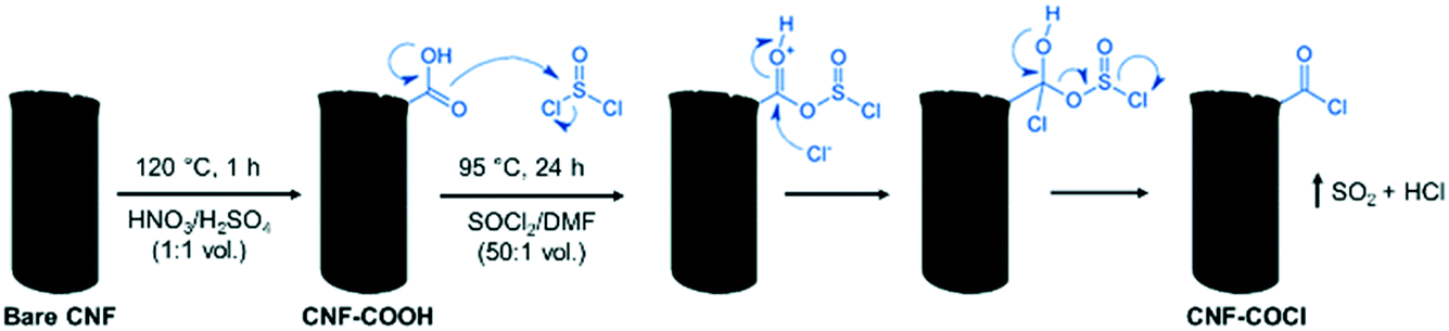 | ||
| Scheme 1 Surface acyl chlorination of the carbon nanofiber support (scheme adapted).37 | ||
Selective decarbonylation of stearic acid
The catalytic conversion of stearic acid (SA) was carried out in duplicate in a 25 mL Schlenk tube glass reactor according to the procedure described by Le Nôtre and co-workers.9 In a typical experiment, 284.5 mg of SA, 48.8 mg of DPE-phosphine ((oxydi-2,1-phenylene)bis(diphenylphosphine)), 10 mg of as-prepared AnPd/CNF catalyst, 0.139 mL of triethylamine (Et3N), 0.220 mL of anhydride acetic (Ac2O), and 4 ml of 1,3-dimetil-3,4,5,6-tetrahidro-2(1H)-pyrimidinone (DMPU) were added into the reactor. After air displacement by a N2 stream, the reaction mixture was stirred for 18 h at 110 °C under reflux, maintaining the inert atmosphere. The catalyst was introduced into the reactor without any prior treatment or activation.Scheme 2 shows the chemical compounds involved in the decarbonylation reaction of stearic acid to 1-heptadecene. Anhydride acetic (Ac2O) was used as a reagent for the activation of stearic acid to stearic anhydride which undergoes oxidative addition to initiate the catalytic cycle.5 DPE-phosphine and triethylamine were used to stabilize the catalytic palladium species and to prevent 1-heptadecene isomerization, respectively.5,9 Furthermore, DMPU was chosen as a solvent because its high polarity enables high selectivity and conversion.8
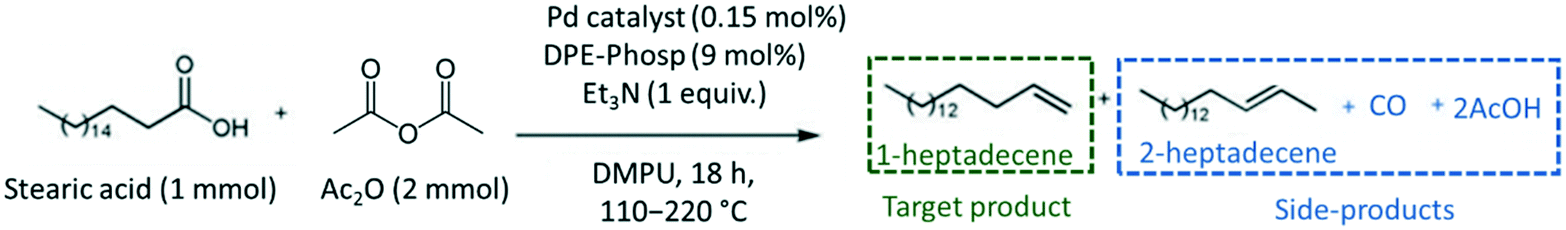 | ||
| Scheme 2 Pd-Catalysed decarbonylation reaction of stearic acid to 1-heptadecene. | ||
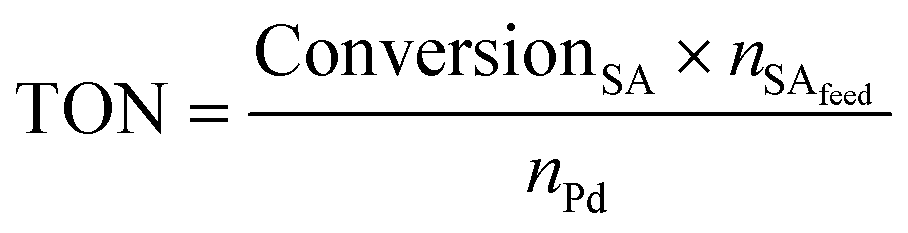
The Pd amount (mol% Pd) loaded into the reactor was calculated with respect to the starting number of moles of stearic acid as follows:
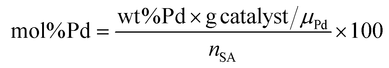 | (1) |
Quantification and identification of the liquid products were conducted on a CLARUS 580 (Perkin Elmer) gas chromatograph (GC) equipped with an FID detector (330 °C) and a 30 m length/250 μm diameter Elite-5 column (CrossbondTM: 5% diphenyl–95% dimethylpolysiloxane). Due to the high polarity of the unreacted SA, a previous derivatization procedure was carried out to prevent its retention in the GC column. For this, the as-resultant liquid product was heated at 60 °C for 1 h under a N2 stream to evaporate the AcOH formed during the decarbonylation reaction. Then, N,O-bis(trimethylsilyl)trifluoroacetamide (BSTFA) was added in a ratio of 0.270 mL mL−1 liquid product, and the mixture was heated again at 60 °C for 1 h. This procedure allows the reaction between the hydroxyl group of stearic acid and BSFTA to form trimethylsilyl stearate, which is a less polar compound and elutes more easily through the column.39 Finally, the catalyst was removed using a 0.22 μm syringe filter and the amber coloured liquid was placed into a vial for GC analysis.
Chemical identification of the products was performed by matching the GC retention times with known standards, whereas quantitative analysis was carried out using calibration curves of each compound. Due to the low solubility of the unreacted stearic acid at room temperature in DMPU, its retention during the filtering and the identification of only 1-heptadecene and 2-heptadecene as reaction products (gas chromatography-mass spectrometry, Varian GC 3800/Saturn 2200 MS), the SA conversion was calculated as the sum of yields of both products as shown in eqn (2):
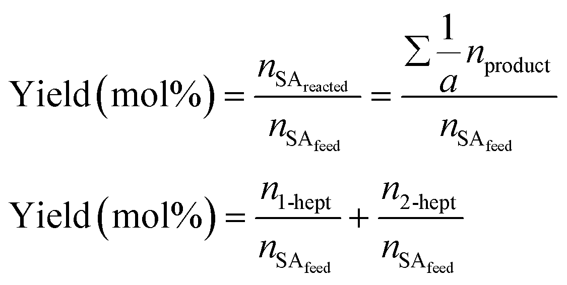 | (2) |
 | (3) |
 | (4) |
Material characterization
Elemental analysis (EA) of C, N, H, O was carried out in a Thermo Flash 1112 furnace with a detection limit of 0.05 wt%. Pd content was measured by inductively coupled plasma optical emission spectrometry (ICP-OES) on a Spectroblue (AMETEK) analyser, using the sodium peroxide fusion procedure to dilute the samples.Chemical surface composition was characterized by X-ray photoelectron spectroscopy (XPS) on an ESCAPlus (OMICROM) spectrometer using non-monochromatized MgAlα radiation (hυ = 1486.7 eV). All the spectra were analysed using the CASA® XPS software by applying a Shirley-type background.
Crystalline phase identification was carried out by powder X-ray diffraction (XRD) on a Bruker D8 Advance diffractometer operated with Ni-filtered CuKα radiation (λ = 1.5406 Å). XRD patterns were recorded from 10° to 80° 2θ degrees with a step size of 0.05° and were analysed using the DIFRAC Plus EVA 8.0 software. Crystallite size calculations were performed by fitting the XRD patterns in TOPAS® software applying Rietveld analysis (LVol-IB, volume averaged column height calculated from the integral breadth).
Porosity and specific surface areas were obtained from N2-physisorption at 77 K using a Micromeritics ASAP2020 instrument. Prior to the analysis, the samples were degassed at 150 °C for 5 h. The specific surface area was calculated according to the Brunauer–Emmett–Teller (BET) equation in the p/p0 range of 0.01–0.10. The micropore volume was estimated by the t-plot method using the Harkins y Hura thickness equation. The total pore volume was obtained at the maximum relative pressure reached by the adsorption branch (p/p0 > 0.989).
Chemical bond identification was performed by Fourier transform infrared (FTIR) and Raman spectroscopy. FTIR spectra were collected on a VERTEX 70 (Bruker) spectrometer from 400 to 4000 cm−1 with a resolution of 1.9 cm−1. Raman spectra were recorded using a Horiba Jobin-Yvon HR800 UV confocal microscope, with a 532 nm laser excitation beam.
Nuclear magnetic resonance (NMR) spectroscopy was used to elucidate the molecular structure of the [Pd2(An)2Cl2] complex synthesized. The 1H NMR spectra of both the [Pd2(An)2Cl2] complex and the free anthranilic acid were recorded in acetone-d6 on a Bruker Avance 400 MHz instrument, by using the standard reference SiMe4 (1H). Chemical shifts (δ) and coupling constants (J) are given in ppm and Hz, respectively, and the signal assignments were based on 1H–1H COSY experiments.
High-resolution scanning transmission electron microscopy (HR-STEM) was used to determine the morphology, size and dispersion of the palladium species impregnated over the CNFs. Micrographs were taken on a FEI Titan Low-Base 60–300 STEM microscope (Advanced Microscopy Laboratory-LMA, INA) equipped with a Cs-probe corrector (CESCOR-0.09 nm spatial resolution, CEOS GmbH) and a high-angle annular dark-field imaging (HAADF) detector. Before imaging, samples were dispersed on amorphous carbon-coated copper grids and then exposed to an electron beam shower for 20 min in order to remove any organic contamination. In some cases, an additional plasma cleaning for 1.5 seconds was used. In addition, energy-dispersive X-ray (EDX) spectroscopy was used to obtain qualitative information about the chemical composition of the particles identified.
Recyclability and leaching tests
Catalyst stability and its utilization efficiency were evaluated by recovering the catalyst and reusing it several times for the SA decarbonylation reaction at 140 °C. To facilitate the recycling of the catalyst, the reaction was scaled up to 40 mg catalyst. Immediately after the reaction was finished, a small portion of the resultant liquid product was saved for GC-MS analysis. The other portion was mixed with an equal volume of anhydrous toluene (99.8%, Sigma-Aldrich) to dissolve the unreacted SA and then the solid catalyst was separated and recovered by centrifugation at 9500 rpm for 2 h at 20 °C. After supernatant removal, the catalyst was washed with anhydrous toluene and dried overnight at 60 °C in a vacuum oven. The as-recovered catalyst was repeatedly used for the SA decarbonylation reaction, without introducing a fresh catalyst to the reactive liquid medium. The proportion of the reactants SA, Et3N, DPE-phosphine, Ac2O, and DMPU was adjusted considering the amount of the recovered catalyst used. Leaching of the active palladium species was determined by inductively coupled plasma optical emission spectrometry (ICP-OES) of the spent catalyst after use.Results and discussion
[Pd2(An)2Cl2] complex characterization
The chemical structure of the synthesized di-μ-chloro-bis[palladium(II) anthranilate] complex was investigated using a large set of analysis techniques including 1H-NMR, FTIR, Raman spectroscopy, X-ray diffraction and XPS spectroscopy. Scheme 3 shows the chemical structure of the [Pd2(An)2Cl2] complex suggested by the characterization results detailed hereafter, which is consistent with similar compounds reported in the literature.40 Accordingly, this binuclear palladium complex involves coordination with the amino and carboxylate groups from the anthranilate ligand, forming two six-membered chelate rings bridged by two chlorine atoms.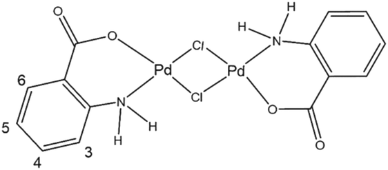 | ||
| Scheme 3 Suggested chemical structure of the synthesized di-μ-chloro-bis[palladium(II) anthranilate] ([Pd2(An)2Cl2]) complex. Numerical scheme for 1H NMR spectroscopic studies. | ||
The 1H NMR spectra of both the free anthranilic acid and the [Pd2(An)2Cl2] complex obtained in acetone-d6 are shown in Fig. 1. The [Pd2(An)2Cl2] complex exhibited two sets of signals associated with two different species. The major species correspond to those in which the anthranilic acid is coordinated to the palladium centre (black boxes), while the minority ones are related to free anthranilic acid (grey circles). In the Pd complex, all the aromatic signals appear to be more deshielded with smaller coupling constants than those present in the free ligand spectrum (3JH3−H4 = 8.1 Hz (free acid),3JH3−H4 = 7.4 Hz (Pd); Fig. S1 and S2,† respectively). This is indicative of metal complexation and suggests that the anthranilic acid is attached to the palladium centre. On the other hand, when a coordinating solvent such as dimethyl sulfoxide DMSO-d6 was used for the analysis, the organic ligand seemed to be displaced from the metal centre and only signals associated with free anthranilic acid could be observed (Fig. S3†). In the case of acetone-d6, the anthranilic acid was partially released (1:0.87) from the palladium coordination sphere. This ratio was calculated using the integrals of the H3 protons from the [Pd2(An)2Cl2] complex (black boxes) and the released anthranilic acid (grey circles).
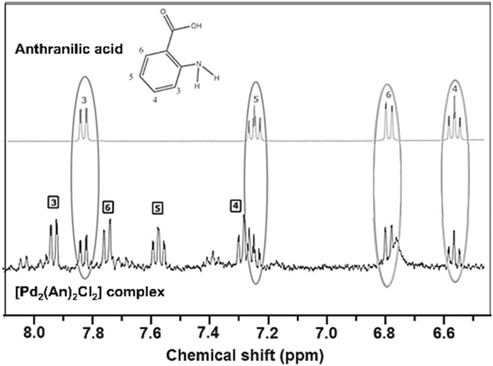 | ||
| Fig. 1 1H NMR spectra of the expanded view of the aromatic region of anthranilic acid and the [Pd2(An)2Cl2] complex obtained in acetone-d6. | ||
Further information about the chemical bonding in the palladium complex was obtained by IR spectroscopy. Fig. 2 shows the near- and mid-infrared spectra of the free anthranilic acid and the [Pd2(An)2Cl2] complex. Anthranilic acid exhibited a very rich set of signals in the infrared range evaluated. The characteristic stretching frequencies of ν(C![[double bond, length as m-dash]](https://www.rsc.org/images/entities/char_e001.gif) O) and ν(C–O) were detected at 1670 cm−1 and 1370 cm−1, respectively. Interestingly, the ν(OH) stretching and δ(OH) bending vibrations from the carboxylic acid (–COOH) were identified at 2534 cm−1 and 935 cm−1.41 However, upon palladium complexation, these signals disappeared and two new peaks corresponding to the νas(COO−) antisymmetric and the νs(COO−) symmetric stretching vibrations emerged at 1610 and 1419 cm−1, respectively.42 This suggests that the ionized carboxylate group (COO−) might be involved in the coordination of the palladium centre by deprotonation of the –COOH from the anthranilic acid.43 According to Nakamoto,44 the separation between νas(COO−) and νs(COO−) vibrations (denoted as Δν(as–s)) gives information about the interaction between the COO− group and the metal atom. When Δν(as–s)-values are larger than those of the ionic form of the free ligand, a monodentate coordination mode occurs as in the case of the [Pd2(An)2Cl2] complex synthesized in this work (Δν(as–s) Pd complex = 191 > Δν(as–s) sodium anthranilate = 135).45 The δ(NH2) bending and ν(C–N) stretching vibrations, centred at 1585 cm−1 and 1275 cm−1 respectively, also underwent some changes. The δ(NH2) band, initially broad in the anthranilic acid spectrum, was split into two sharp signals ascribed to the νas(COO−) and δ(NH2) vibrations. A frequency shift in the δ(NH2) band of 29 cm−1 towards lower wavelengths was recorded in the complex spectrum. Additionally, upon complexation, an increase in the ν(C–N) stretching and the formation of a new broad band at 522 cm−1 due to the ν(Pd–N) stretching were also observed.46 These results suggest that both the nitrogen atom from the amine group and the oxygen atom from the ortho-carboxylic group could coordinate the palladium centre through a six-membered chelate as proposed in Scheme 3. No signals related to the Pd–Cl or Pd–O vibrations were observed in the spectra because these occur in the far infrared region below 400 cm−1.44
O) and ν(C–O) were detected at 1670 cm−1 and 1370 cm−1, respectively. Interestingly, the ν(OH) stretching and δ(OH) bending vibrations from the carboxylic acid (–COOH) were identified at 2534 cm−1 and 935 cm−1.41 However, upon palladium complexation, these signals disappeared and two new peaks corresponding to the νas(COO−) antisymmetric and the νs(COO−) symmetric stretching vibrations emerged at 1610 and 1419 cm−1, respectively.42 This suggests that the ionized carboxylate group (COO−) might be involved in the coordination of the palladium centre by deprotonation of the –COOH from the anthranilic acid.43 According to Nakamoto,44 the separation between νas(COO−) and νs(COO−) vibrations (denoted as Δν(as–s)) gives information about the interaction between the COO− group and the metal atom. When Δν(as–s)-values are larger than those of the ionic form of the free ligand, a monodentate coordination mode occurs as in the case of the [Pd2(An)2Cl2] complex synthesized in this work (Δν(as–s) Pd complex = 191 > Δν(as–s) sodium anthranilate = 135).45 The δ(NH2) bending and ν(C–N) stretching vibrations, centred at 1585 cm−1 and 1275 cm−1 respectively, also underwent some changes. The δ(NH2) band, initially broad in the anthranilic acid spectrum, was split into two sharp signals ascribed to the νas(COO−) and δ(NH2) vibrations. A frequency shift in the δ(NH2) band of 29 cm−1 towards lower wavelengths was recorded in the complex spectrum. Additionally, upon complexation, an increase in the ν(C–N) stretching and the formation of a new broad band at 522 cm−1 due to the ν(Pd–N) stretching were also observed.46 These results suggest that both the nitrogen atom from the amine group and the oxygen atom from the ortho-carboxylic group could coordinate the palladium centre through a six-membered chelate as proposed in Scheme 3. No signals related to the Pd–Cl or Pd–O vibrations were observed in the spectra because these occur in the far infrared region below 400 cm−1.44
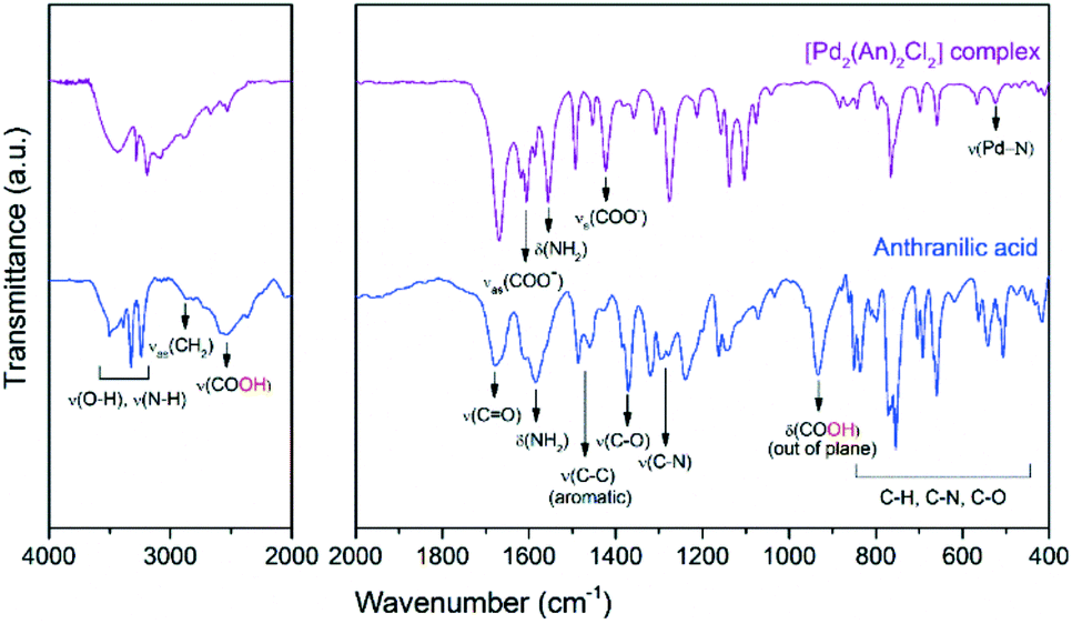 | ||
| Fig. 2 FTIR spectra of free anthranilic acid and the [Pd2(An)2Cl2] complex. Near-infrared (left) and mid-infrared (right) regions. | ||
For comparison purposes, Fig. 3 shows the Raman spectra of the [Pd2(An)2Cl2] complex and its basic constituents, anthranilic acid and PdCl2. The free anthranilic acid exhibited sharp and high-intensity peaks in the recorded spectrum. Besides its characteristic Raman frequencies, a strong peak related to the lattice vibration was observed at 142 cm−1 indicating its crystalline nature.47 PdCl2 showed an intense band composed of two peaks at 265 cm−1 and 310 cm−1, corresponding to the symmetric and antisymmetric stretching of Pd–Cl bonds, respectively.47 The low-intensity δs(Pd–Cl) mode was also observed at 144 cm−1, which is due to the restrained number of terminal Pd–Cl stretches in the “infinite” chain configuration of pure α-PdCl2.48
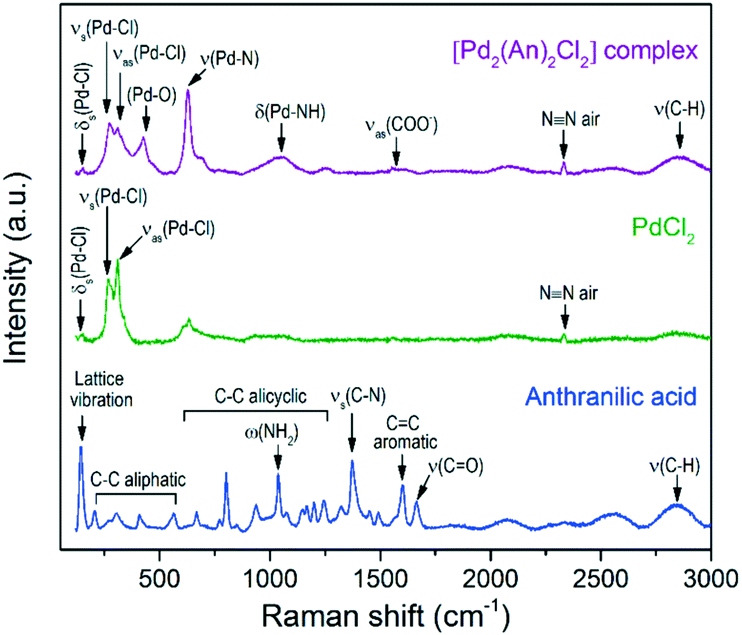 | ||
| Fig. 3 Raman spectra of the [Pd2(An)2Cl2] complex and its basic constituents, anthranilic acid and PdCl2. | ||
After complexation of palladium with anthranilic acid, the former peaks became less intense and more symmetrical, which is related to the shortening of such Pd–Cl chains.48 In the [Pd2(An)2Cl2] spectrum, besides the Pd–Cl vibration, the Pd–O,49ν(Pd–N),50δ(Pd–NH)50 and νas(COO−)51 modes were also identified at 426, 628, 1048 and 1571 cm−1, respectively. These vibration modes agree with those observed in the FTIR analysis and support the proposed chemical structure of the metal complex depicted in Scheme 3.
The chemical analysis data of the [Pd2(An)2Cl2] complex obtained by elemental analysis, ICP-OES and XPS are summarized in Table 1. Interestingly, the relative content of C, H and N was lower than that calculated from the chemical formula of the complex, whereas the palladium content was found to be higher. This result can be due to the anthranilic acid being partially displaced from the Pd coordination sphere by the EtOH:H2O mixture used during the washing process. As a result, in addition to the [Pd2(An)2Cl2] complex, some non-coordinated Pd particles could be retained in the filter while the anthranilic acid passed through it. This fact was corroborated by elemental analysis of the yellow-coloured filtrate in which some traces of anthranilic acid were identified (43.6 wt% C, 3.95 wt% H, 9.78 wt% N). The formation of Pd particles might be also due to the fact that after synthesis the anthranilate ligand was oxidized by contact with air, promoting palladium reduction.42
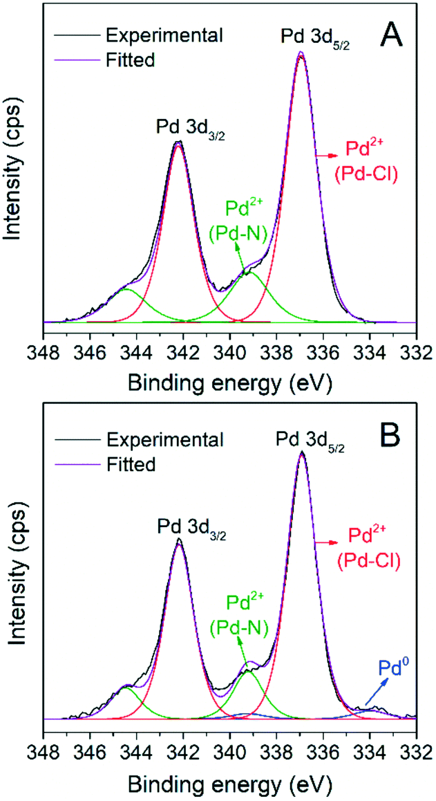
The XPS spectrum in Fig. 4 shows the Pd 3d5/2, 3d3/2 doublet of the [Pd2(An)2Cl2] complex with a spin–orbital splitting of 5.3 eV and an intensity ratio I5/2/I3/2 = 1.5. Upon deconvolution of the 3d doublet, three different Pd species could be detected. Besides the low intensity metallic Pd0 3d5/2 band, centred at 334.1 eV, two signals corresponding to the Pd2+ state were identified at 337.1 eV and 338.5 eV, respectively. The first one was associated with the Pd–Cl bond,52,53 while the second one was ascribed to the Pd–N bond contribution.54,55
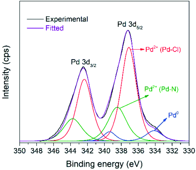 | ||
| Fig. 4 XPS spectrum of Pd 3d5/2, 3d3/2 for the synthesized [Pd2(An)2Cl2] complex. | ||
Fig. 5 shows the powder XRD pattern of the [Pd2(An)2Cl2] complex. A rich set of sharp diffraction peaks was observed at low 2θ angles revealing the crystalline nature of the synthesized material. Interestingly, these reflections were shifted with respect to the free anthranilic acid (PDF file 03-0274) and PdCl2 (PDF file 86-1888) powder diffraction patterns; therefore they can be ascribed to the [Pd2(An)2Cl2] complex crystal structure itself.56 Additionally, the reflections due to the face-centred cubic crystal structure of Pd(0) were also observed at 40.0° (111), 46.5° (200) and 67.9° (220) (PDF file 88-2335), which supports the idea that the [Pd2(An)2Cl2] complex was impurified to some extent with non-coordinated palladium particles. A Pd(0) crystallite size of 11.0 nm was obtained upon fitting the Pd(0) diffraction peaks applying Rietveld analysis (LVol-IB, TOPAS® software). On the other hand, no diffraction peaks associated with palladium oxide were identified indicating the high oxidation resistance of such Pd(0) nanoparticles.
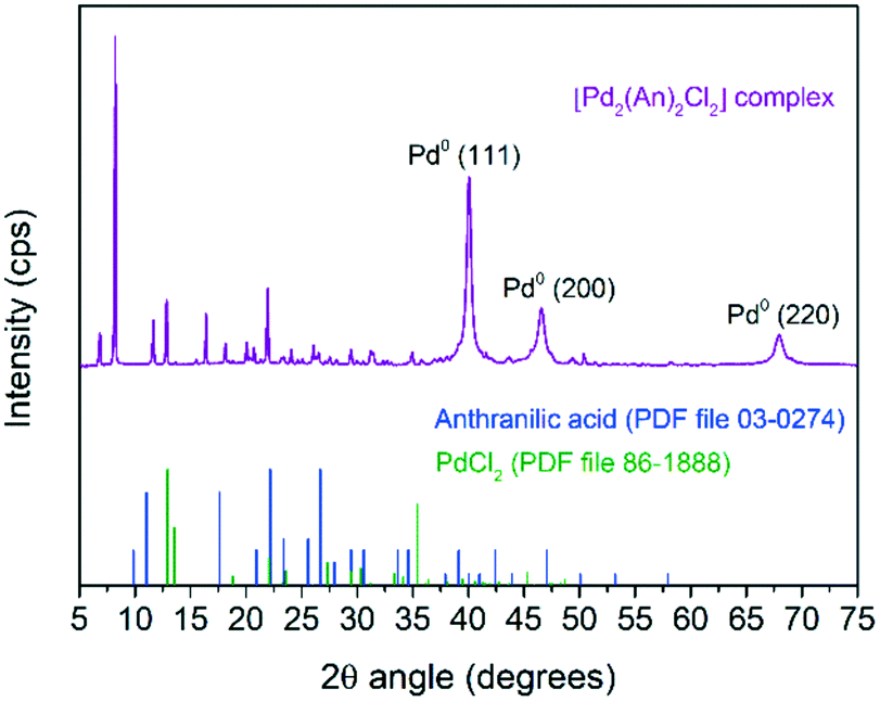 | ||
| Fig. 5 Powder XRD pattern of the synthesized [Pd2(An)2Cl2] complex. | ||
Catalyst characterization
The AnPd/CNF catalysts prepared either with EtOH or DMF were characterized in order to determine their physical and chemical surface properties. Table 2 summarizes the chemical analysis composition of the prepared materials, performed by EA, ICP-OES and XPS. Both catalysts impregnated with DMF and EtOH exhibited a palladium content around 1.5 wt%, which is consistent with the nominal amount incorporated. Upon impregnation, the relative content of C, H and N in the CNF–COCl support was not greatly affected due to the low amount of the [Pd2(An)2Cl2] complex incorporated. Nevertheless, some differences in the surface chemical composition of the catalysts were observed by XPS. AnPd/CNF (EtOH) exhibited a higher surface Pd content and lower atomic percentages of C, O and N than AnPd/CNF (DMF). This result can be attributed to the anthranilic acid being partially displaced from the complex coordination sphere during impregnation, thereby leaving some non-coordinated Pd particles over the CNF–COCl support.| Sample | Elemental analysis (wt%) | ICP-OES (wt%) | XPS (at%) | ||||||
|---|---|---|---|---|---|---|---|---|---|
| % C | % H | % N | % Pd | % C | % O | % N | % Cl | % Pd | |
| CNF–COCl support | 92.6 | 0.4 | 0.8 | 0.00 | 92.3 | 7.0 | 0.4 | 0.38 | 0.00 |
| AnPd/CNF (DMF) | 92.8 | 0.5 | 0.9 | 1.50 | 88.6 | 8.4 | 1.2 | 1.43 | 0.42 |
| AnPd/CNF (EtOH) | 93.1 | 0.4 | 0.6 | 1.49 | 89.8 | 7.7 | 0.6 | 0.55 | 1.34 |
Fig. 6 shows the Pd 3d XPS spectra of both catalysts and the peak deconvolution of the 3d5/2, 3d3/2 doublet. For the AnPd/CNF (EtOH) catalyst, four components were identified; the less oxidized species located at 334.1 eV and 336.9 eV were attributed to Pd0 and Pd2+ in the Pd–Cl bond, respectively.52,53 The two remaining components, centred at 338.9 eV and 341 eV, were related to Pd2+ in the Pd–N bond with a different electronic environment.54,55 In the case of the AnPd/CNF (DMF) catalyst, only two 3d5/2 doublets were detected at 336.9 eV and 337.8 eV, which were related to Pd2+ in Pd–Cl and Pd–N bonds, respectively.53
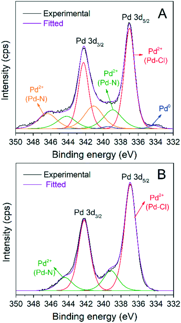 | ||
| Fig. 6 Pd 3d XPS spectra of the impregnated catalysts: (A) AnPd/CNF (EtOH) and (B) AnPd/CNF (DMF). | ||
The XRD patterns of the AnPd/CNF catalysts and the CNF–COCl support are shown in Fig. 7. All patterns show a highly intense peak at 26° and two weak peaks at 43° and 45° 2θ degrees, assigned to the (002), (100) and (101) reflections of graphitic carbon (PDF file 75-2078), respectively.57 Additionally, the reflection peaks of the face-centred cubic crystal structure of Pd(0) (PDF file 88-2335) were also present in the pattern of the impregnated catalysts. The mean crystallite size of such Pd(0) particles calculated by applying Rietveld analysis (LVol-IB, TOPAS® software) was 9.3 nm for AnPd/CNF (EtOH) and 12.1 nm for AnPd/CNF (DMF). These nanoparticles could have been formed either during the impregnation of CNF–COCl or during the synthesis of the [Pd2(An)2Cl2] complex, as discussed before.
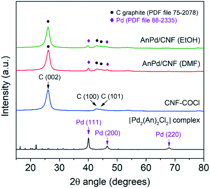 | ||
| Fig. 7 Powder XRD patterns of the AnPd/CNF catalysts and the CNF–COCl support. | ||
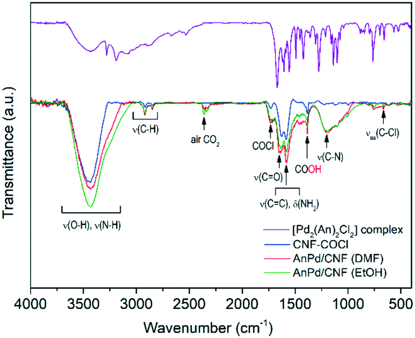
Further information about the chemical interaction between the [Pd2(An)2Cl2] complex and the catalysts was obtained from the FTIR spectra shown in Fig. 8. Either the CNF–COCl support or the impregnated catalysts exhibited two weak bands at 1760 cm−1 and 660 cm−1 corresponding to the acetyl chloride ν(–COCl) and the νas(C–Cl) stretching vibrations, respectively.37 After complex impregnation, a new broad band emerged at 1190 cm−1, which is due to the C–N stretching of the amide group.58
 | ||
| Fig. 8 FTIR spectra of the synthesized materials. | ||
This suggests that the [Pd2(An)2Cl2] complex is anchored to the CNF–COCl support through amide bonding as shown in Scheme 4. Accordingly, acyl chloride (–COCl) groups serve as anchor sites, which form amide linkages with the [Pd2(An)2Cl2] complex through a nucleophilic addition/elimination reaction during the impregnation process.
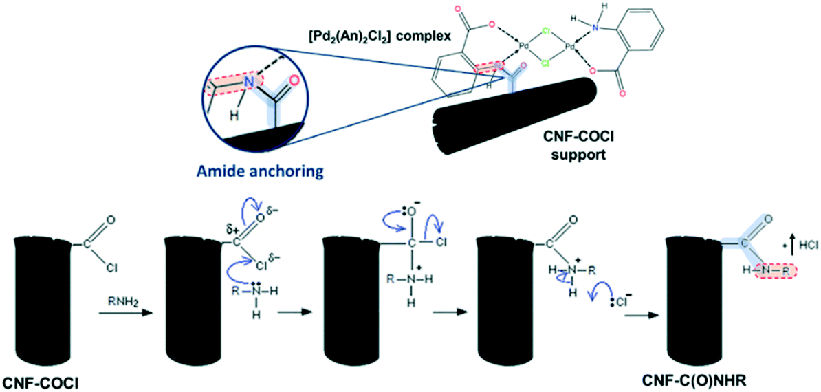 | ||
| Scheme 4 (Top) Anchoring between the [Pd2(An)2Cl2] complex and the CNF–COCl support and (bottom) nucleophilic addition/elimination in the reaction between acyl chlorides and amines. | ||
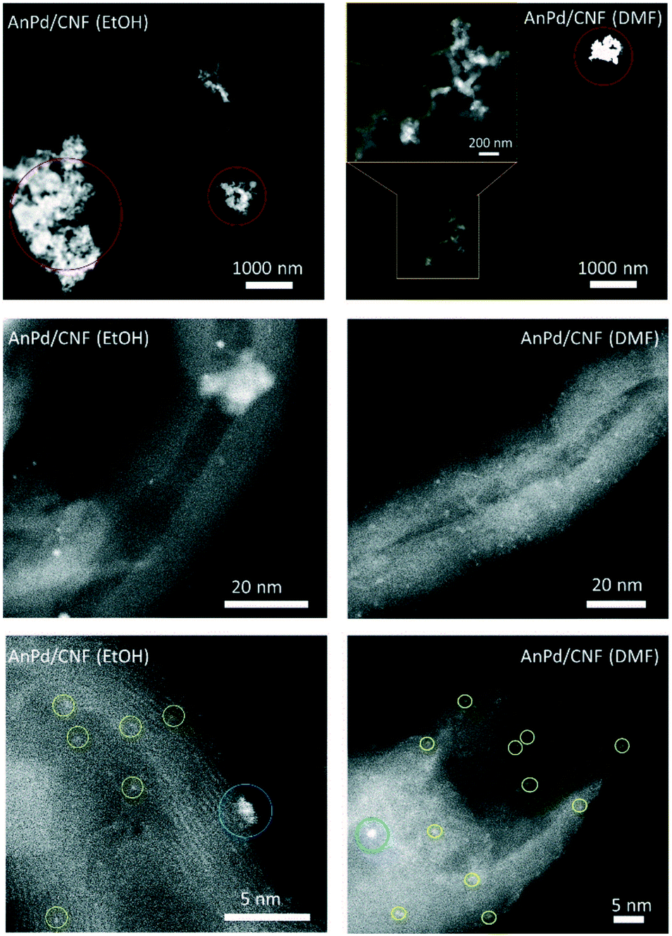
HR-STEM was used to determine the size, morphology, and dispersion of the palladium species impregnated over the CNFs. Fig. 10 shows the HAADF-STEM images of the AnPd/CNF catalysts at different magnifications. Particle counting measurements of different areas allowed the estimation of the average size of the Pd particles observed as bright spots in the HAADF-STEM images. Three different groups of particles were observed, Pd sub-nanometric nanoparticles (yellow circles), Pd clusters (blue circles) and large Pd aggregates (red circles). AnPd/CNF (DMF) showed well dispersed Pd sub-nanometric particles of ca. 0.7 nm and a high number of Pd clusters of about 1.1 nm. A few Pd aggregates composed of primary particles of ca. 21.7 nm were also observed. Conversely, AnPd/CNF (EtOH) presented a lower dispersion of both Pd sub-nanometric particles and Pd clusters than AnPd/CNF (DMF), resulting in CNFs with large naked areas and bulky Pd aggregates with primary particles around 33.6 nm. In this catalyst, only a small amount of ca. 0. 2 nm Pd sub-nanometric particles and Pd clusters of about 1.3 nm could be observed.
Here, a better dispersion of subnanometric particles was related to a higher population of [Pd2An2Cl2] species, instead of the large aggregates in which Pd crystals were identified (Fig. S4 and S5†). The bigger particle size obtained by STEM compared with the XRD crystallite size might be due to the presence of large palladium aggregates with different crystallite sizes.
In line with the characterization results, the differences observed in the dispersion of the [Pd2(An)2Cl2] complex may be attributed to the solvent effect. EtOH, which is a polar protic solvent, might de-coordinate the Pd centre by displacing the anthranilic acid ligand; in addition, it might react with the acyl chloride (–COCl) groups on the CNF–COCl surface by a nucleophilic addition/elimination reaction (Scheme 5), blocking the anchoring sites for complex impregnation thereby restraining its dispersion.
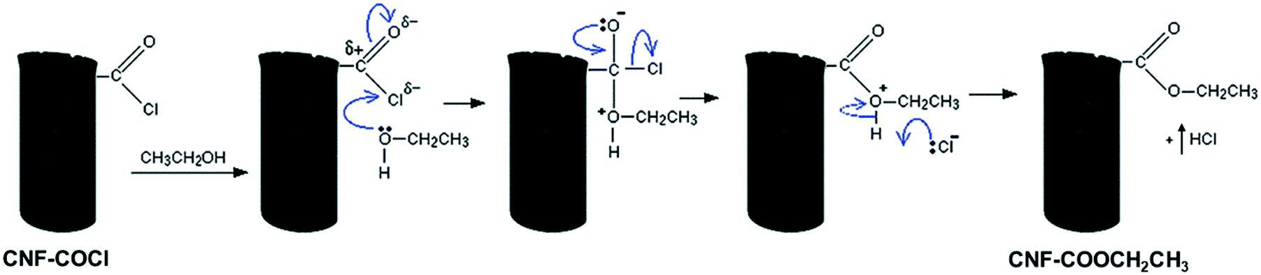 | ||
| Scheme 5 Blocking of the acyl chloride groups by a nucleophilic addition/elimination reaction with EtOH. | ||
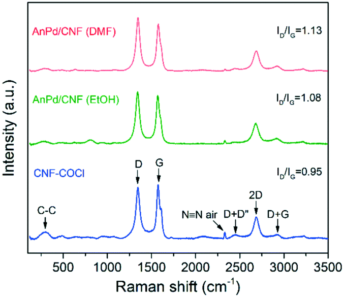
Additionally, the materials were analysed by Raman spectroscopy, as shown in Fig. 9. Both the catalysts and the bare CNF–COCl support exhibited characteristic strong G (1576 cm−1) and D (1345 cm−1) bands, attributed to the in-plane vibration of the sp2 bonds and the disorder degree in the sp2-hybridized structure, respectively. Other less intense bands were also detected from 2350 to 3000 cm−1, which are related to the overtones and combinations among the D, G, and D' modes.59 The relative intensity between the D and G band (ID/IG) is often associated with the density of defects occurring due to sp3 hybridization of the carbonaceous framework. Since Raman scattering is strongly sensitive to the electronic structure of the CNFs, a change in the ID/IG ratio can be related to structural modifications derived from complex immobilization.60 After impregnation with the [Pd2(An)2Cl2] complex, the relative intensity of the D band was increased in both catalysts, which reflects the chemical interaction between the complex and the CNF–COCl support. Interestingly, the ID/IG ratio of AnPd/CNF (DMF) was slightly higher than that of the AnPd/CNF (EtOH) catalyst, which suggests that, when impregnating with DMF, the functionalization degree of AnPd/CNF (DMF) could be higher than when EtOH was used as a solvent.
 | ||
| Fig. 9 Raman spectra of the AnPd/CNF catalysts and the CNF–COCl support. | ||
Table 3 shows the textural properties of the prepared materials. A general decrease in the BET surface area and pore volume of the bare CNF–COCl support was observed in the impregnated catalysts, a consequence of pore blockage after complex impregnation. No differences between the impregnated catalysts were observed, due to the low amount of the [Pd2(An)2Cl2] complex incorporated.
Selective decarbonylation of stearic acid to 1-heptadecene
Highly dispersed AnPd/CNF catalysts were tested for the selective decarbonylation of stearic acid to produce 1-heptadecene. The influence of the impregnation solvent and the reaction temperature on the catalytic performance of the prepared materials is summarized in Table 4. For comparison purposes, a homogeneous reaction was performed using the unsupported [Pd2(An)2Cl2] complex with a Pd loading of 5 mol% under the same reaction conditions (entry 1). The AnPd/CNF catalyst prepared with EtOH exhibited the lowest catalytic performance with a selectivity to 1-heptadecene of 54 mol%, a yield of 0.5 mol% and a TON = 4 (entry 2). However, when the aprotic solvent DMF was used for [Pd2(An)2Cl2] complex impregnation, the activity and selectivity were notably increased to TON = 18 and 87 mol%, respectively, reaching values close to the unsupported [Pd2(An)2Cl2] complex catalysed reaction with a yield of 2.6 mol% (entry 3). This enhancement in the catalytic performance can be attributed to the high palladium dispersion in the AnPd/CNF (DMF) catalyst. Since the [Pd2(An)2Cl2] complex was more homogeneously dispersed in AnPd/CNF (DMF) than in the case of AnPd/CNF (EtOH) (Fig. 10), this catalyst may contain a higher number of active palladium atoms on the surface available to participate in the catalytic process.| Entry | Palladium catalyst | Catalytic system | Pd loadinga (mol%) | T (°C) | Yieldb (mol%) | 1-hept select.b (mol%) | TON | TOFc (h−1) | Ref. |
|---|---|---|---|---|---|---|---|---|---|
| a Calculated by eqn (1). b Determined as the average of two experiments by GC-MS spectroscopy. c Turnover frequency (TOF) = TON/reaction time (h). d Conditions: 1 mmol SA, 2 mmol Ac2O, 4 mL DMPU, 0.09 mmol DPE-phosphine (9 mol%), 1 mmol Et3N (1 equiv.), 18 h reaction time, 4.5 mL reaction volume. e ND: not determined. f Determined by 1H NMR using methyl benzoate as an internal standard. g Conditions: 20 mmol SA, 6 portions of Ac2O 1 + 0.14 + 0.12 + 0.10 + 0.09 + 0.08 equiv. added every 30 min, Xantphos (0.06 mol%), (t-Bu)4biphenol (0.5 mol%), successive distillation of AcOH, 3 h reaction time. h Conditions: 1 mmol SA, 2 mmol Ac2O, 2 mL DMPU, 0.09 mmol Et3N (9 mol%), 15 h reaction time. i Conditions: 1 mmol SA, 1 mmol Ac2O, 2 mL DMPU, 0.1 mmol DPE-phosphine (10 mol%), 15 min reaction time. | |||||||||
| 1 | [Pd2(An)2Cl2] complex | Homogeneous precatalyst | 5.00 | 110 | 90 | 97 | 18 | 1.0 | This workd |
| 2 | AnPd/CNF (EtOH) | Homogeneous precatalyst supported on CNFs | 0.14 | 110 | 0.5 | 54 | 4 | 0.2 | This workd |
| 3 | AnPd/CNF (DMF) | Homogeneous precatalyst supported on CNFs | 0.14 | 110 | 2.6 | 87 | 18 | 1.0 | This workd |
| 4 | CNF–COCl support | — | 0 | 110 | 0.1 | 75 | 0 | 0 | This workd |
| 5 | AnPd/CNF (DMF) | Homogeneous precatalyst supported on CNFs | 0.14 | 125 | 3.4 | 86 | 23 | 1.3 | This workd |
| 6 | AnPd/CNF (DMF) | Homogeneous precatalyst supported on CNFs | 0.14 | 140 | 71 | 90 | 484 | 26.9 | This workd |
| 7 | AnPd/CNF (DMF) | Homogeneous precatalyst supported on CNFs | 0.14 | 180 | 72 | 92 | 495 | 27.5 | This workd |
| 8 | AnPd/CNF (DMF) | Homogeneous precatalyst supported on CNFs | 0.14 | 220 | 61 | 89 | 423 | 23.5 | This workd |
| 9 | 0.6% Pd/CNF | Heterogeneous catalyst | 0.06 | 180 | 7.8 | 84 | 112 | 6.2 | This workc |
| 10 | PdCl2 | Homogeneous catalyst | 1.79 | 110 | 100 | 97 | NDe | NDe | Le Nôtre, et al.d9 |
| 11 | PdCl2(triphenylphosphine)2 | Homogeneous catalyst | 0.05 | 132 | 67f | 89f | 1338 | 446 | Liu, et al.g5 |
| 12 | Pd-(Cinnamyl)Cl(DPEPhos) | Homogeneous precatalyst | 0.50 | 110 | 88f | 99f | 176 | 11.7 | Chatterjee, et al.h62 |
| 13 | 10% Pd/C | Heterogeneous catalyst | 1.00 | 250 | 70f | 98f | 70 | 280 | Chatterjee and Jenseni14 |
 | ||
| Fig. 10 HAADF-STEM images of the catalysts at different magnifications showing the presence of Pd sub-nanometric particles (yellow circles), Pd clusters (blue circles) and large Pd aggregates (red circles). | ||
Regarding the CNF–COCl support, it was observed that it does not have any catalytic activity for the decarbonylation reaction (entry 4). Aiming to improve the catalytic performance of the AnPd/CNF (DMF) catalyst in the decarbonylation of SA, the reaction temperature was varied from 110 °C to 220 °C. Both the yield and the catalyst activity were improved by increasing the reaction temperature, while the selectivity to 1-heptadecene ranged from 86 mol% to 92 mol%, without significant variations (entries 3, 5–8). A prominent enhancement in the yield and TON was registered at 140 °C, reaching values as high as 71 mol% and 484, respectively (entry 6), even much higher than those obtained during homogenous catalysis with the unsupported [Pd2(An)2Cl2] complex at 110 °C (entry 1). A further increase of 35 °C in the reaction temperature caused only a slight increase of 11 units in the TON (entry 7). However, when the temperature was raised to 220 °C, the yield and the TON were decreased to 61 mol% and 423 (entry 8). This can be due to thermal degradation of the [Pd2(An)2Cl2] complex or formation of off-cycle species that reduce the AnPd/CNF (DMF) catalyst activity.62,63 In order to elucidate the catalytic activity of the Pd aggregates observed in the catalysts, the decarbonylation reaction was carried out at 180 °C using a previously reported heterogeneous catalyst composed of 0.6 wt% Pd nanoparticles of around 2.5 nm supported on carboxylated CNF–COOH (Fig. S6†).64 The prepared 0.6% Pd/CNF catalyst exhibited an extremely low yield of 7.8 mol% (entry 9) when compared with the supported AnPd/CNF (DMF) catalyst (72 mol% SA conversion yield) under the same reaction conditions (entry 7). This result demonstrates that Pd(0) nanoparticles have a low contribution to the catalytic process while the dispersed [Pd2An2Cl2] complex is the most active phase responsible for the decarbonylation reaction.
In a similar homogeneous PdCl2(triphenylphosphine)2 catalysed decarbonylation reaction, Liu and co-workers5 achieved a surprising TON = 1338 under a very low Pd loading (0.05 mol%), with close values of yield and selectivity (entry 11). Nevertheless, in order to promote the reactivity and to ensure the α-selectivity, this reaction required acidic additives like (t-Bu)4biphenol and a portionwise addition of Ac2O every 30 min with sequential distillation of the formed AcOH, making the process certainly laborious.
On the other hand, the extraordinary performance of the AnPd/CNF (DMF) catalyst developed in this work is an interesting achievement since the decarbonylation reaction was performed under relatively mild operation conditions (atmospheric pressure and 140 °C) with a very low Pd loading in solution (0.14 mol%). For instance, this catalyst attained an activity (TON = 484, TOF = 26.9) almost three times higher than a homogeneous precatalyst comprising Pd-(cinnamyl)Cl (DPEPhos) (entry 12). Even more, when compared with a heterogeneous 10 wt% Pd/C catalyst, evaluated using the same reaction strategy and reactants, we could obtain a superior TON = 484, with similar values of yield and α-selectivity using an 85 mol% lower palladium loading in solution (entry 13). This result highlights the exceptional catalytic performance of such catalysts containing the active phase in a subnanometric dispersion state, compared to conventional homogeneous and heterogeneous catalysts.
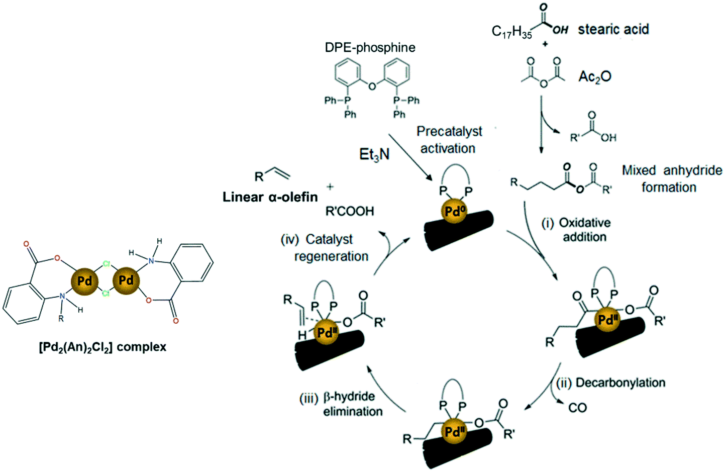
The widely accepted reaction mechanism for fatty acid decarbonylation to linear α-olefins via palladium-based catalysts is depicted in Scheme 6.4,14,62 The reaction is presumed to start with the formation of a mixed anhydride between the carboxylic group of the fatty acid and the sacrificial anhydride (Ac2O). This mixed anhydride facilitates the oxidation of the active Pd(0) centres by oxidative addition, giving Pd(II) carboxylate species (i). Next, the carboxylate ligand undergoes decarbonylation to generate alkylpalladium(II) releasing carbon monoxide (ii). Finally, the catalytic cycle is completed by the β-hydride elimination of the alkyl ligand to deliver the olefin product (iii) and the subsequent regeneration of the active Pd(0) catalyst (iv). In this work, the impregnated [Pd2(An)2Cl2] complex is thought to act as a precatalyst, which is activated into the active Pd(0) species responsible for initiating the decarbonylation reaction, by triethylamine and DPE-phosphine serving as a promoter and stabilizing agent, respectively.62,65,66 However, a more detailed study must be conducted to address the activation of the [Pd2(An)2Cl2] complex during the first stage of the decarbonylation catalytic cycle.
 | ||
| Scheme 6 Possible reaction mechanism of the AnPd/CNF-catalyzed decarbonylation of stearic acid to linear α-olefins (scheme adapted).14,58 | ||
Catalyst recyclability and post-mortem characterization
In order to determine the stability and utilization efficiency of the catalysts developed in this work, AnPd/CNF (DMF) was selected for leaching and recyclability studies due to its high catalytic performance. The catalyst was separated from the liquid product by centrifugation at 9500 rpm for 2 h at 20 °C, resulting in a recovery efficiency of about 80% with respect to the initial amount of catalyst incorporated. The recovered catalyst was evaluated again for the SA decarbonylation reaction at 140 °C. Table 5 summarizes the performance of the AnPd/CNF-DI (DMF) catalyst after four reutilization tests.| Entry | AnPd/CNF-DI (DMF) catalyst | Yield (mol%) | 1-Hept select. (mol%) | TON | TOF (h−1) |
|---|---|---|---|---|---|
| Conditions: 40 mg AnPd/CNF catalyst (1.5 wt% Pd), 4 mmol stearic acid, 8 mmol Ac2O, 16 mL DMPU, 0.36 mmol DPE-phosphine, 4 mmol Et3N, final volume of reaction = 18 mL. 18 h reaction time, 140 °C. | |||||
| 1 | Cycle 1: fresh catalyst | 16.8 | 92 | 129 | 7.2 |
| 2 | Cycle 2: recovered catalyst | 17.0 | 90 | 129 | 7.2 |
| 3 | Cycle 3: recovered catalyst | 17.3 | 92 | 131 | 7.3 |
| 4 | Cycle 4: recovered catalyst | 12.0 | 90 | 87 | 4.8 |
The yield was maintained up to the 3rd cycle (ca. 17%) although an 18% yield decrease was observed after the 4th cycle involving a TON decrease from 129 (TOF = 7.2 h−1) to 86.9 (TOF = 4.8 h−1). Interestingly, the selectivity to 1-heptadecene was maintained at ca. 90 mol% in all cycles. It is important to point out that, aiming to facilitate the recovery of the catalyst, the amount of reactants in the recyclability tests was 4-fold scaled regarding the standard experiments summarized in Table 4. However, although the reaction was scaled up, the molar proportion of each component was retained and the yield of the fresh catalyst in the first cycle of the recycling tests (cycle 1, Table 5) was about 1/4 of that of the standard test (entry 6, Table 4), under the same operating conditions (140 °C, 18 h). This fact may be tentatively assigned to diffusion problems due to the limited dimensions of the reaction tube. Temperature gradients along the reactor cannot be discarded. More efforts should be done in order to improve the reaction in larger-scale rectors, although the results presented herein evidence the high stability of the catalyst.
The heterogeneity of the catalytic system was evaluated by measuring the leaching of Pd species from the recovered AnPd/CNF (DMF) catalyst after the first reutilization cycle. Table 6 summarizes the chemical composition of the AnPd/CNF (DMF) catalyst before and after the decarbonylation reaction. ICP-OES analysis revealed the great stability of the [Pd2(An)2Cl2] complex anchored to the CNF–COCl support. After the reaction, the AnPd/CNF (DMF) catalyst only lost 0.2 wt% of the palladium active phase (13% from the starting catalyst), which is similar to a highly stable Rh(I) complex supported over carbon black.36 EA and XPS analyses show that the N and Cl atomic percentages of the catalyst were decreased upon reaction, while the palladium surface content was increased from 0.4 to 1.3 at%. This surface Pd enrichment was related to a slight lift-off of anthranilate ligand moieties in the [Pd2(An)2Cl2] complex during the reaction, leaving some non-coordinated palladium sites exposed on the catalyst surface. This is consistent with the Pd(0) signal appearing at ∼334.1 eV in the Pd 3d XPS spectrum of the AnPd/CNF (DMF) catalyst after use (Fig. 11). The fact that the catalyst remains stable after this modification can be attributed to the stabilizing effect of DPE-phosphine (Scheme 6), which is thought to bind to the metal throughout the catalytic cycle, acting as a protective barrier which prevents catalyst deactivation. This stabilizing effect has been observed in similar palladium catalysts for decarbonylative dehydration of fatty acids.14,62
| Sample | Elemental analysis (wt%) | ICP-OES (wt%) | XPS (at%) | ||||||
|---|---|---|---|---|---|---|---|---|---|
| % C | % H | % N | % Pd | % C | % O | % N | % Cl | % Pd | |
| Fresh AnPd/CNF (DMF) | 92.8 | 0.5 | 0.9 | 1.50 | 88.6 | 8.4 | 1.2 | 1.4 | 0.4 |
| Used AnPd/CNF (DMF) | 92.3 | 0.3 | 0.6 | 1.30 | 85.1 | 11.5 | 0.5 | 0.5 | 1.3 |
 | ||
| Fig. 11 Pd 3d XPS spectra of the AnPd/CNF (DMF) catalyst (A) before and (B) after the decarbonylation reaction. | ||
Regarding the crystalline phases, no significant differences were observed between the XRD patterns of the AnPd/CNF (DMF) catalyst before and after the decarbonylation reaction (Fig. 12). Both diffraction peaks derived from the graphitic carbon structure of the CNF–COCl support and those of the face-centred cubic crystal structure of Pd(0) were still present in the spent catalyst. Nonetheless, after the reaction a moderate increase from 12.1 nm to 13.4 nm was observed in the Pd crystallite size calculated by applying Rietveld analysis (LVol-IB, TOPAS® software). This result supports the idea that some non-coordinated Pd sites could be aggregated after partial leaching of the [Pd2(An)2Cl2] complex, as previously noticed in the XPS analysis (Fig. 11).
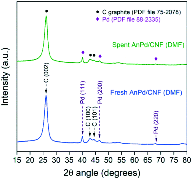 | ||
| Fig. 12 Powder XRD patterns of the AnPd/CNF (DMF) catalyst before and after the decarbonylation reaction. | ||
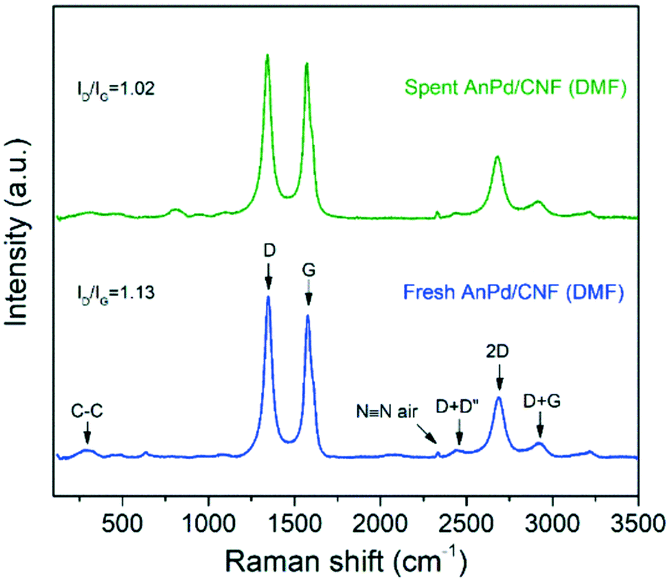
Similarly, the Raman spectrum of the AnPd/CNF (DMF) catalyst was preserved upon the decarbonylation reaction, and only a slight decrease in the ID/IG ratio from 1.13 to 1.02 was recorded (Fig. 13). The reduction in the ID/IG ratio implies a decrease in the defect degree of the carbonaceous structure of the catalyst support. Considering the mild reaction conditions used during SA decarbonylation and that the graphitization of the CNF support was not largely affected (Fig. 12), it can be inferred that this slight reduction in the ID/IG ratio was caused by a decrease in the functionalization degree after the leaching of the [Pd2(An)2Cl2] complex.60,61
 | ||
| Fig. 13 Raman spectra of the AnPd/CNF (DMF) catalyst before and after the decarbonylation reaction. | ||
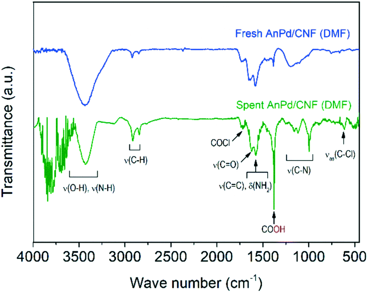
Further information about the chemical bonds in the AnPd/CNF (DMF) catalyst was obtained by FTIR spectroscopy (Fig. 14). In order to compare the relative content of functional groups in the catalysts and considering that the graphitic carbon structure of the CNF support was preserved upon the reaction (Fig. 12 and 13), the signals were normalized to obtain CC equal transmittance (1582 cm−1). Upon the decarbonylation reaction, the intensity of the peak centred at 3500 cm−1 (related to ν(O–H) and ν(N–H) vibrations) was decreased, while those of the two peaks centred at 2921 cm−1 and 2850 cm−1 (ascribed to the ν(C–H) vibrations) were increased. Moreover, a notable increase in the intensity of the COOH peak was observed at 1380 cm−1. These results suggest the transformation of the amide anchoring sites –C(O)NHR of the catalyst support into –COOH groups as a result of [Pd2(An)2Cl2] complex leaching.
 | ||
| Fig. 14 FTIR spectra of the AnPd/CNF (DMF) catalyst before and after the decarbonylation reaction. | ||
On the other hand, the ν(C–N) peak at 1195 cm−1 suffered a splitting into three different peaks centred at 1155 cm−1, 1116 cm−1 and 1000 cm−1. This splitting in the ν(C–N) vibration can be related to a change in the electronegativity of the bonding neighbourhood during the decarbonylation reaction, in which the closely overlapped bands provide different relative intensity contributions.67 Particularly, the FTIR spectrum of the spent AnPd/CNF (DMF) catalyst shows the generation of several peaks in the region 3500–4000 cm−1. According to Hookes' law, these groups should be related to strongly bonded small atoms. The creation of such strongly bonded functionalities has a high degree of uncertainty; however, they might appear due to adsorption of new functional groups from the remaining product moieties on the catalyst surface during the reaction.
Conclusions
In this work, a di-μ-chloro-bis[palladium(II) anthranilate] complex was successfully synthesized and highly dispersed over acyl chlorinated CNFs by incipient wetness impregnation with different solvents. The use of EtOH as an impregnation solvent decreased the palladium dispersion on the AnPd/CNF (EtOH) catalyst, resulting in a material with large naked areas and bulky palladium aggregates. This fact was attributed to the ability of EtOH to displace the anthranilate ligand from the Pd centre and occupy the chlorine anchor sites on the functionalized CNF–COCl support. Consequently, this material exhibited a low catalytic activity for the selective decarbonylation of stearic acid to 1-heptadecene. In contrast, the use of DMF as an impregnation solvent allowed a better dispersion of the palladium species and, therefore, the AnPd/CNF (DMF) catalyst exhibited a better catalytic performance with a selectivity to 1-heptadecene of 87 mol%, a yield of 2.6 mol% and a TON = 18 at 110 °C.Interestingly, the increase of the reaction temperature up to 140 °C resulted in a prominent enhancement of the AnPd/CNF (DMF) catalyst activity without a decrease in α-selectivity. The best catalytic performance (90 mol% selectivity, 71 mol% SA conversion, and TON = 484) was achieved when operating the decarbonylation reaction at 140 °C with a very low palladium loading in solution (0.14 mol%). The post-mortem catalyst characterization and the recyclability tests evidenced the high stability of the catalyst. The mild reaction conditions used in this work and the high activity of the developed catalyst represent a step forward for energy and cost savings in the sustainable transformation of fatty acids into valuable chemicals such as linear α-olefins.
Conflicts of interest
There are no conflicts to declare.Acknowledgements
The authors are grateful for the financial support from FEDER and the Spanish Economy and Competitiveness Ministry (MINECO) (ENE2017-83854-R). EO acknowledges MINECO for her PhD grant under the frame of the aforementioned project. The authors gratefully acknowledge “Laboratorio de Microscopías Avanzadas” at “Instituto de Nanociencia de Aragón−Universidad de Zaragoza” for offering access to their microscope and expertise. W. Henao acknowledges the financial support from the grant sponsored by Fundación Carolina (Madrid, Spain) and the University of Zaragoza. We acknowledge support of the publication fee by the CSIC Open Access Publication Support Initiative through its Unit of Information Resources for Research (URICI).References
- C. P. Nicholas, Appl. Catal., A, 2017, 543, 82–97 CrossRef CAS.
- G. P. Belov and P. E. Matkovsky, Pet. Chem., 2010, 50(4), 283–289 CrossRef.
- A. Chatterjee, S. H. H. Eliasson and V. R. Jensen, Catal. Sci. Technol., 2018, 8(6), 1487–1499 RSC.
- X. Zhang, F. Jordan and M. Szostak, Org. Chem. Front., 2018, 5(16), 2515–2521 RSC.
- Y. Liu, K. E. Kim, M. B. Herbert, A. Fedorov, R. H. Grubbs and B. M. Stoltz, Adv. Synth. Catal., 2014, 356(1), 130–136 CrossRef CAS PubMed.
- J. A. Miller, J. A. Nelson and M. P. Byrne, J. Org. Chem., 1993, 58(1), 18–20 CrossRef CAS.
- G. A. Kraus and S. Riley, Synthesis, 2012, 44(19), 3003–3005 CrossRef CAS.
- L. J. Gooßen and N. Rodríguez, Chem. Commun., 2004, 724–725 RSC.
- J. Le Nôtre, E. L. Scott, M. C. Franssen and J. P. Sanders, Tetrahedron Lett., 2010, 51(29), 3712–3715 CrossRef.
- J. A. Lopez-Ruiz, H. N. Pham, A. K. Datye and R. J. Davis, Appl. Catal., A, 2015, 504, 295–307 CrossRef CAS.
- J. A. Lopez-Ruiz and R. J. Davis, Green Chem., 2014, 16(2), 683–694 RSC.
- R. Stern and G. Hillion, U.S. Pat. Appl., 4554397A, 1985 Search PubMed.
- D. Wang, S. H. Hakim, D. M. Alonso and J. A. Dumesic, Chem. Commun., 2013, 49(63), 7040–7042 RSC.
- A. Chatterjee and V. R. Jensen, ACS Catal., 2017, 7(4), 2543–2547 CrossRef CAS.
- L. Liu and A. Corma, Chem. Rev., 2018, 118(10), 4981–5079 CrossRef CAS PubMed.
- B. C. Gates, M. Flytzani-Stephanopoulos, D. A. Dixon and A. Katz, Catal. Sci. Technol., 2017, 7(19), 4259–4275 RSC.
- J. Liu, ACS Catal., 2016, 7(1), 34–59 CrossRef.
- F. Chen, X. Jiang, L. Zhang, R. Lang and B. Qiao, Chin. J. Catal., 2018, 39(5), 893–898 CrossRef CAS.
- X. Cui, W. Li, P. Ryabchuk, K. Junge and M. Beller, Nat. Catal., 2018, 1(6), 385 CrossRef CAS.
- C. Zhang, L. Chen, H. Cheng, X. Zhu and Z. Qi, Catal. Today, 2016, 276, 55–61 CrossRef CAS.
- Z. W. Chen, L. X. Chen, C. C. Yang and Q. Jiang, J. Mater. Chem. A, 2019, 7(8), 3492–3515 RSC.
- D. I. Kochubey, V. V. Chesnokov and S. E. Malykhin, Carbon, 2012, 50(8), 2782–2787 CrossRef CAS.
- D. A. Bulushev, M. Zacharska, A. S. Lisitsyn, O. Y. Podyacheva, F. S. Hage, Q. M. Ramasse, U. Bangert and L. G. Bulusheva, ACS Catal., 2016, 6(6), 3442–3451 CrossRef CAS.
- Q. Cheng, L. Yang, L. Zou, Z. Zou, C. Chen, Z. Hu and H. Yang, ACS Catal., 2017, 7(10), 6864–6871 CrossRef CAS.
- C. Rivera-Cárcamo and P. Serp, ChemCatChem, 2018, 10(22), 5058–5091 CrossRef.
- S. Eskandari, G. Tate, N. Leaphart and J. R. Regalbuto, Nanoparticle synthesis via electrostatic adsorption using incipient wetness impregnation, ACS Catal., 2018, 8(10), 383 Search PubMed.
- Y. Elkasabi, Q. Liu, G. Choi, Y. Strahan, A. A. Boateng and J. R. Regalbuto, Bio-Oil Hydrodeoxygenation Catalysts Produced Using Strong Electrostatic Adsorption, Fuel, 2017, 207, 510 CrossRef CAS.
- L. D'Souza, L. Jiao, J. R. Regalbuto, J. T. Miller and A. J. Kropf, Preparation of silica-and carbon-supported cobalt by electrostatic adsorption of Co(III) hexaammines, J. Catal., 2007, 248(2), 165–174 CrossRef.
- P. Serp and E. Castillejos, ChemCatChem, 2010, 2(1), 41–47 CrossRef CAS.
- E. Pérez-Mayoral, V. Calvino-Casilda and E. Soriano, Catal. Sci. Technol., 2016, 6(5), 1265–1291 RSC.
- M. R. Axet, J. Durand, M. Gouygou and P. Serp, Adv. Organomet. Chem., 2019, 71, 53–174 CrossRef.
- H. Li, H. X. Zhang, X. L. Yan, B. S. Xu and J. J. Guo, New Carbon Mater., 2018, 33(1), 1–11 CrossRef.
- J. H. Bitter, J. Mater. Chem., 2010, 20(35), 7312–7321 RSC.
- K. L. Klein, A. V. Melechko, T. E. McKnight, S. T. Retterer, P. D. Rack, J. D. Fowlkes, D. C. Joy and M. L. Simpson, J. Appl. Phys., 2008, 103(6), 3 CrossRef.
- J. Li, M. J. Vergne, E. D. Mowles, W. H. Zhong, D. M. Hercules and C. M. Lukehart, Carbon, 2005, 43(14), 2883–2893 CrossRef CAS.
- A. A. Tregubov, D. B. Walker, K. Q. Vuong, J. J. Gooding and B. A. Messerle, Dalton Trans., 2015, 44(17), 7917–7926 RSC.
- C. C. Gheorghiu, B. F. Machado, C. S. M. de Lecea, M. Gouygou, M. C. Román-Martínez and P. Serp, Dalton Trans., 2014, 43(20), 7455–7463 RSC.
- E. Ochoa, D. Torres, R. Moreira, J. L. Pinilla and I. Suelves, Appl. Catal., B, 2018, 239, 463–474 CrossRef CAS.
- F. Q. Yang, K. Feng, J. Zhao and S. P. Li, J. Pharm. Biomed. Anal., 2009, 49(5), 1172–1178 CrossRef CAS PubMed.
- P. K. Santra and P. Sagar, J. Mol. Catal. A: Chem., 2003, 197(1–2), 37–50 CrossRef CAS.
- M. Samsonowicz, T. Hrynaszkiewicz, R. Świsłocka, E. Regulska and W. Lewandowski, J. Mol. Struct., 2005, 744, 345–352 CrossRef.
- T. G. Ros, M. K. Van Der Lee, A. J. Van Dillen, J. W. Geus and D. C. Koningsberger, J. Mol. Catal. A: Chem., 2002, 186(1–2), 13–24 CrossRef CAS.
- J. Kalembkiewicz, M. Kosińska and L. Zapała, Coord. Chem. Rev., 2017, 348, 25–53 CrossRef CAS.
- K. Nakamoto, Coordination, Organometallic, and Bioinorganic Chemistry, Wiley, New York, 5th edn, 1997 Search PubMed.
- A. F. Borowski and D. J. Cole-Hamilton, Polyhedron, 1993, 12(14), 1757–1765 CrossRef CAS.
- J. R. Durig, R. Layton, D. W. Sink and B. R. Mitchell, Spectrochim. Acta, 1965, 21(8), 1367–1378 CrossRef CAS.
- V. Susindran, S. Athimoolam and S. A. Bahadura, J. Chem. Pharm. Res., 2012, 4(10), 4628–4636 Search PubMed.
- R. Besnard, J. Cambedouzou, G. Arrachart, X. F. Le Goff and S. Pellet-Rostaing, RSC Adv., 2015, 5(95), 77619–77628 RSC.
- G. Wang, X. Yu, X. Cao, H. Li and Z. Zhang, J. Raman Spectrosc., 2000, 31(12), 1051–1055 CrossRef CAS.
- N. Trendafilova, I. Georgieva, G. Bauer, S. Varbanov and N. Dodoff, Spectrochim. Acta, Part A, 1997, 53(6), 819–828 CrossRef.
- G. Socrates, Infrared and Raman characteristic group frequencies: tables and charts, John Wiley & Sons, 2004 Search PubMed.
- J. F. Moulder, W. F. Stickle, P. E. Sobol and K. D. Bomben, Handbook of X-ray photoelectron spectroscopy, Perkin-Elmer Corporation, Eden Prairie, Minnesota, 1992 Search PubMed.
- L. Arroyo-Ramí, R. Montano-Serrano, R. G. Raptis and C. R. Cabrera, J. Nanotechnol., 2009, 971423 Search PubMed.
- G. Kumar, J. R. Blackburn, R. G. Albridge, W. E. Moddeman and M. M. Jones, Inorg. Chem., 1972, 11(2), 296–300 CrossRef CAS.
- M. Hasik, A. Bernasik, A. Drelinkiewicz, K. Kowalski, E. Wenda and J. Camra, Surf. Sci., 2002, 507, 916–921 CrossRef.
- P. Kavitha and K. L. Reddy, Arabian J. Chem., 2016, 9(5), 640–648 CrossRef CAS.
- R. Moreira, E. Ochoa, J. L. Pinilla, A. Portugal and I. Suelves, Catalysts, 2018, 8(4), 127 CrossRef.
- R. Afshari, S. Mazinani and M. Abdouss, Nano, 2015, 10(01), 1550010 CrossRef CAS.
- M. S. Dresselhaus, G. Dresselhaus, R. Saito and A. Jorio, Phys. Rep., 2005, 409(2), 47–99 CrossRef.
- K. A. Wepasnick, B. A. Smith, J. L. Bitter and D. H. Fairbrother, Anal. Bioanal. Chem., 2010, 396(3), 1003–1014 CrossRef CAS PubMed.
- J. M. Englert, C. Dotzer, G. Yang, M. Schmid, C. Papp, J. M. Gottfried, H.-P. Steinrück, E. Spiecker, F. Hauke and A. Hirsch, Nat. Chem., 2011, 3(4), 279 CrossRef CAS PubMed.
- A. Chatterjee, S. H. Hopen Eliasson, K. W. Törnroos and V. R. Jensen, ACS Catal., 2016, 6(11), 7784–7789 CrossRef CAS.
- P. G. Gildner and T. J. Colacot, Organometallics, 2015, 34(23), 5497–5508 CrossRef CAS.
- E. Frecha, D. Torres, A. Pueyo, I. Suelves and J. L. Pinilla, Appl. Catal., A, 2019, 585, 117182 CrossRef.
- J. Muzart, J. Mol. Catal. A: Chem., 2009, 308(1–2), 15–24 CrossRef CAS.
- P. R. Melvin, D. Balcells, N. Hazari and A. Nova, ACS Catal., 2015, 5(9), 5596–5606 CrossRef CAS.
- S. R. Ryu, I. Noda and Y. M. Jung, Appl. Spectrosc., 2010, 64(9), 1017–1021 CrossRef CAS PubMed.
Footnotes |
| † Electronic supplementary information (ESI) available. See DOI: 10.1039/d0cy00322k |
| ‡ These authors contributed equally to this work. |
| This journal is © The Royal Society of Chemistry 2020 |