 Open Access Article
Recent advances and prospects of inkjet printing in heterogeneous catalysis
Hesam
Maleki
 and
Volfango
Bertola
 *
*
Laboratory of Technical Physics, University of Liverpool, Liverpool, L69 3GH, UK. E-mail: volfango.bertola@liverpool.ac.uk; Tel: +44 (0)1517944804
First published on 16th April 2020
Abstract
Recent advances in inkjet printing technology for applications relating to heterogeneous catalysis are presented. Catalysts lie at the heart of most chemical reactions where raw materials are converted to value-added products. Therefore, synthesis and immobilization of active catalysts in the reactor are of great importance. Inkjet printing is an additive manufacturing technology introduced recently as a useful method for the fabrication and application of catalysts as a class of functional materials. Inkjet printing provides special features which can be tailored to the design of high-efficient catalytic processes. This review presents an overview of the technology along with developments and challenges associated with the combination of inkjet printing and heterogeneous catalysis, such as ink preparation, thin-film properties and real-life applications.
1 Introduction
Heterogeneous catalysis plays a key role in the production of about 90% of chemicals worldwide.1 Because of its significant impact, researchers in chemical and energy areas, have invested much effort in the development of this field.2 In heterogeneous catalysis, reactions usually occur at the solid catalyst-fluid interface, and the activity depends on the interactions of reactants and the catalyst surface. Thus, the catalyst surface morphology is as important as the surface chemical composition.3 A great variety of reactors have been developed to immobilize solid catalysts efficiently for catalytic reactions, such as conventional fixed-bed and fluidized-bed reactors or, more recently, using monolithic reactors, membrane reactors and microreactors.4,5 For example, in microreactors, higher surface-to-volume ratio due to small length-scale would lead to heat and mass transfer enhancement. Therefore, this type of reactor is utilized for various reaction types and in-depth kinetic studies.6,7In heterogeneous catalysis, the solid catalyst is normally deposited onto the reactor channel walls for various reaction conditions. Different deposition techniques have been integrated into reactor and microreactor technologies for efficient and uniform catalyst immobilization.8,9 Dip-coating is often used for the layered deposition of catalyst by immersion and withdrawal of the substrate into the catalyst-based solution.10 This method can be used for coating of packed-bed pellets or monolithic reactors which are widely used as automotive catalytic converters.11 Doctor blade and spin-coating are generally used for the coating of flat substrates.12,13 Despite the fast processing and ease of operation, these methods produce large waste of materials.14 Furthermore, they are not suitable for patterned deposition and for producing ultra-thin films.15 Vacuum deposition refers to a class of deposition methods used to coat materials atom-by-atom or molecule-by-molecule onto the substrate.16 Vacuum deposition methods are operated under low pressures (i.e., vacuum) and can create ultra-thin films.17 Physical and chemical vapour deposition methods have been recently used for catalyst deposition.18–20 In spite of the potential advantages provided by vacuum deposition methods, such as monitoring of film thickness and purity, they involve expensive multi-step operations at elevated temperatures.21
Inkjet printing is a fast-growing technology for deposition of functional materials on various substrates in electronics,21,22 pharmaceutical23,24 and micro-engineering industries.25–27 Inkjet printing is a non-contact deposition method which takes an image or pattern data from a computer and applies it onto a substrate using ink in the form of microdroplets.28 This method has a high-precision control over homogenous deposition of picolitre-sized droplets and can be operated at ambient temperature and pressure.29 Moreover, complex patterns can be easily produced by using inkjet printing without the use of physical masks.30 Therefore, it offers cost-effective rapid mass production of various materials from thermosensitive substances31,32 to metal oxides33–35 with minimal waste of materials. Table 1 presents a summary of different deposition techniques in comparison to inkjet printing.
| Spin/dip-coating | Lithography | Vapour deposition | Inkjet printing | |
|---|---|---|---|---|
| Material waste | High | High | Low | Low |
| Working area | Medium | Small | Small | Large |
| Patterning capability | Low | Medium | Low | High |
| Temperature | Low | High | High | Low |
| Mask required | Yes | Yes | Yes | No |
| Process | Simple | Multi-step | Multi-step | Simple |
| Cost | Low | High | High | Low |
Due to the advantages of inkjet printing and the large number of applications, many research groups are active in developing this technique in different fields of technology. Moreover, several review articles have been published focusing on different aspects of the technology such as: (i) inkjet printing of metal oxide-based precursors,36,37 (ii) ink formulation of metal nanoparticles and metal–organic compounds for printed electronics,38 (iii) development of printing technologies and sintering approaches for fabrication of flexible electronics,21,39 (vi) ink drop impact and interaction with the substrate40etc.
The main goal of this work is to summarize and introduce various applications and perspectives associated with the inkjet printing method for designing novel catalytic systems. There have been sporadic reports on the applications of inkjet printing in catalysis.37,41 Liu et al.37 reviewed some applications of inkjet printing for photo- and electro-catalysts as a family of functional metal oxides. Here, there will be more focus on the synthesis of catalyst materials by inkjet printing for chemical and photochemical reactions. Furthermore, the contribution of this technique towards heterogeneous catalysis, future outlooks as well as recent research developments are described.
2 Inkjet printing: methodology
The first modern movable printing press was developed by J. Gutenberg in the 15th century.42 In this printing machine and later conventional derivatives such as offset printing and screen printing, the pressure is applied on the substrate during the ink transfer, which is known as contact-printing.43 In recent printing technologies, ink is transferred to the substrate without applying physical contact between the ink dispenser and the substrate, which is referred to as non-contact-printing.44 In non-contact printing, the substrate is only in contact with the ink containing the printing material, and there is no mechanical pressure on the substrate, which removes the risks of damaging the pre-patterned substrate or of causing contamination. Furthermore, non-contact printing allows for patterned printing and multilayered deposition with high accuracy, resolution and speed.21Inkjet printing as a non-contact method emerged for direct patterned deposition of solution-based materials. In this method, ink is delivered to the nozzle-head from the ink reservoir and ejected in the form of microdroplets. The released ink droplets hit the substrate at specific rates to perform the printing.23 The printed patterns can be created by controlled displacement of either the substrate or the print-head. Then, the printed ink goes through the evaporation and solidification process. Usually, the printed substrate is post-processed at high temperatures in form of thermal annealing, sintering or calcination to remove solvents, increase the adhesion and modify the material structure.45
2.1 Inkjet printing modes
Inkjet printers have two main operational modes: continuous and drop-on-demand (DOD). In continuous inkjet printing, the ink fluid is released from the nozzle in the form of a liquid jet. The liquid jet undergoes the surface tension-driven jet break-up, which is known as Plateau–Rayleigh instability, and breaks up into droplets.45 Continuous inkjet printing is normally used in textile printing and labelling due to high-speed operation.32 Drop-on-demand (DOD) inkjet printing is the method of choice, in most cases, alongside the continuous mode due to higher precision and smaller drop size and flexibility of ink formulations.46In DOD mode, two types of actuators are widely used: piezoelectric actuators and thermal actuators.47 In piezoelectric DOD printing, ink droplets are formed and released by deformation of the piezoelectric actuator induced by an electric field.48 By applying a certain electric potential to the piezoelectric transducer, a pressure wave is created due to a small volume change. The pressure wave moves towards the nozzle and drives out the ink droplet as shown in Fig. 1a. In a thermal drop-on-demand inkjet printer, the ink solution is heated using a Joule heating element placed near the nozzle. A bubble of ink vapour is formed, which routs out an ink microdroplet. In other words, the thermal DOD process uses the evaporation of a tiny volume of ink to create the ink droplet and jetting driving force.32 Therefore, the ink selected for this method should have volatile components such as water or short-chain alcohols. On the other hand, piezoelectric DOD printing is suitable for a wide variety of ink solvents since the ink drop formation and release are based on the ink volume change caused by the fluctuation of the piezoelectric membrane. Furthermore, the rate and size of jetted droplets can be adjusted precisely by regulating the working voltage without the need for temperature alteration.21,32
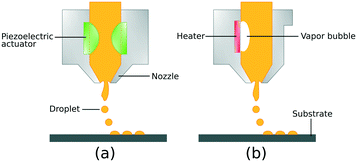 | ||
| Fig. 1 Schematic illustration of drop-on-demand inkjet printing process: (a) piezoelectric DOD mode and (b) thermal DOD mode. | ||
2.2 Ink properties and printing conditions
In the inkjet printing technology, the ink solution should be carefully formulated to have specific properties such as particle size distribution, density, surface tension and viscosity.49 In addition to the ink characterization, the printing condition needs to be regulated to yield stable droplets. In other words, ink solutions should be prepared for a particular printing condition both in terms of stability, and in terms of rheological and interfacial properties. Nanoparticles dispersed in the ink solutions tend to form secondary micron-sized agglomerates leading to particle sedimentation. Moreover, rapid evaporation of the solvent at the nozzle and large particle agglomerates may cause nozzle clogging.50 Therefore, it is preferable to stabilize the inkjet solution using dispersing agents, and use particles with average size as small as 1/50th of the nozzle diameter.46,51 The ink viscosity and surface tension also strongly influence the dynamics of microfluidic droplets and must be carefully controlled and/or optimized. The suggested range for viscosity in DOD inkjet printers is 1–25 mPa s.52 Ink solutions with higher viscosity cannot release smoothly from the nozzle. At the same time, low viscous inks form unstable droplets during the printing process resulting in the formation of satellite micro drops. The suggested surface tension range in DOD mode is 20–50 mN m−1.40 Higher surface tensions hinder the drop formation process and lower surface tensions would lead to air ingestion and dripping of droplets towards the substrate.53Although surface tension and viscosity are the main physical properties that determine the drop formation and size, the jetting capability of the formulated ink also depends on the nozzle size and the printing conditions. These parametric quantities are merged into the Reynolds number and the Weber number, representing the ink fluidic properties:54,55
 | (1) |
 | (2) |
Here, γ, ρ and η are the surface tension, density and dynamic viscosity of the fluid, respectively, d is the nozzle size, and v is the fluid drop velocity. These dimensionless values are usually combined into a single parameter, the inverse Ohnesorge number:
 | (3) |
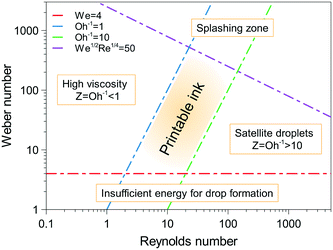 | ||
| Fig. 2 Ink printability region-based the Reynolds and Weber numbers. Reproduced from J. Eur. Ceram. Soc., vol. 31, B. Derby, Inkjet printing ceramics: from drops to solid, pp. 2543–2550, Copyright (2011), with permission from Elsevier.63 | ||
3 Catalyst-based ink development
Ink formulation is a key step in the inkjet printing technology, since the prepared ink should maintain specific properties to meet the printing requirements. The inkjet inks for DOD mode usually contain functional species precursor, carrier solvent and additives. The precursor for catalyst-based inks is composed of metal oxide particles, metal salts or metal-based solutions. To date, there are limited reports on the ink development of inorganic materials due to preparation and storage challenges. This section will summarize the ink formulation requirements and specific approaches to use various components for catalyst-based ink preparation.3.1 Prerequisites
While the basic principles of inkjet printing are rather simple, the printer components such as the printhead and nozzles are complex structures which can operate reliably only with ink fluids with specific properties.60 Therefore, some points need to be addressed in the design of catalyst-based inks:i) The ink formulation should be compatible with the printer components. For example, the carrier solvent should not damage the nozzles and the ink delivery system.
ii) The ink should have viscosity and surface tension within specific ranges to operate in the inkjet printer, and these properties may differ in different printing systems.
iii) Stability is key in designing inks since the agglomeration of ink components would cause nozzle clogging and blockage of ink delivery system thereby limiting the ink lifetime.
iv) The prepared ink should have effective adhesion to the substrate with sufficient hardness after the printing process.
3.2 Carrier solvent
The carrier solvent constitutes the bulk of the ink solution, which mainly determines the ink properties such as viscosity, surface tension, stability, density and evaporation rate. It also dissolves and disperses the metal species and other additive components. The carrier solvents can be categorized into aqueous (or water-based) and non-aqueous solvents.Aqueous inks consist of functional species, catalyst nanoparticles (or metal precursors in our case), and some additives dissolved/dispersed in water. Aqueous inks usually have lower viscosity and evaporation rate, and higher surface tension compared to their non-aqueous counterparts. However, these properties can be tuned to meet the specific inkjet printer requirements by using co-solvents such as alcohols, glycols and surfactants.64 Water is often used in the printing industry as the carrier solvent in aqueous inks due to its safety and availability; however, water-based inks have slow drying rates on non-porous substrates such as glass and steel.65 In addition, they exhibit relatively low stability for dispersed metal nanoparticles.66
Solvent-based inks use organic solvents such as short-chain alcohols (e.g., ethanol, isopropanol, glycols) and toluene as carrier fluid. This class of inks is usually selected to improve the ink stability, lower the surface tension, or increase the viscosity and the evaporation rate.37 One factor in the choice of solvents is the optimum drying rate. Using slow-drying solvents would increase the drying time and energy required. On the other hand, volatile solvents would reduce the solvent removal time and ease the multilayer deposition process; however, fast solvent evaporation at the nozzle may cause clogging. One approach is to use a mixture of solvents to optimize the evaporation rate.60 The solvent interaction with the substrate should also be considered as it affects adhesion and print quality. By choosing a suitable solvent, the formulated inks can be deposited onto various substrates with enhanced print quality and uniformity.
3.3 Functional species precursor
Catalyst species used as functional precursors can appear in the form of either colloidal catalyst nanoparticles or metal-based solutions in the ink medium. The colloidal nanoparticles in the solution could be the result of direct synthesis (e.g., sol–gel method), or could be added and dispersed as dry nanopowders.Parkinson et al.67–69 developed libraries of electrocatalysts (e.g., Cr, Fe, Cu, Pt, Ru, Ir) for oxygen evolution reaction via combinatorial studies using the inkjet printing technology. Metal salt precursors (e.g., metal nitrates and chlorides) were added to the ink solutions containing water and glycols. The formulated inks were then printed onto the substrate using a lab-scale inkjet printer. The printed layers were converted to mixed metal oxides under air pyrolysis process. After kinetic studies, the optimised electrocatalysts were obtained and further characterized.
Hu et al.70 used the inkjet printing method for the direct synthesis and fabrication of platinum catalysts by using a chloroplatinic solution as catalyst precursor. The chloroplatinic acid solution was added to water/ethylene glycol as a carrier solvent and then sent to a commercial microdispensing system. After printing, the coated substrates were placed in a furnace under methanol flow at 250 °C to produce the platinum catalyst.
The nanoparticle concentration in the ink formulation can be increased to some extent; however, this could lead to sedimentation and viscosity increase at high concentrations due to particle-particle interactions.66 The relation between the ink viscosity and dispersion concentration may be described according to the hard-sphere model of viscosity developed by Krieger and Dougherty:77
 | (4) |
In eqn (4), φ is the particle volume fraction and φm is the maximum packing fraction which is 0.74, 0.64 and 0.6 for monodispersed spheres, dense random packing and loose random packing, respectively.78,79 [η] is the intrinsic viscosity which is 2.5 for hard spheres, while the relative viscosity, ηr, shows the ratio of dispersion fluid viscosity to the viscosity of the pure fluid.78,80
Gebauer et al.66 studied the dispersion of various metal oxide powders (CuO, ZnO, SnO2 and In2O3) prepared by chemical vapour synthesis. The nanoparticles were dispersed in ethylene glycol/water (xEG = 0.865) mixture as ink medium. A dilute solution of nitric acid was added to enhance stability. The stability measurements of several prepared inks as well as measured viscosities at different volume fractions (φ) are shown in Fig. 3.
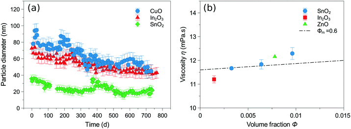 | ||
| Fig. 3 (a) Stability measurements of CuO (4 wt%), In2O3 (1 wt%) and SnO2 (2 wt%) based ink solutions containing ethylene glycol (xEG = 0.865), (b) measured viscosities for different concentrations of SnO2 (2, 4, 6 wt%), In2O3 (1 wt%) and ZnO (4 wt%), and φm = 0.6 line calculated according to Krieger-Dougherty model.77 Reproduced from J. Colloid Interface Sci., vol. 526, J. S. Gebauer, V. Mackert, S. Ognjanović, M. Winterer, Tailoring metal oxide nanoparticle dispersions for inkjet printing, pp. 400–409, Copyright (2018), with permission from Elsevier.66 | ||
Dittmeyer et al.81 developed a procedure for inkjet printing of Al2O3 nanoparticles in stainless steel microchannels. The inkjet inks were prepared by dispersing alumina nanoparticles in different mixtures of water/ethylene glycol, and ink properties were optimized by changing the solvent ratios and adding polyethylene glycol as a copolymer. The ink formula containing only water showed agglomerations resulting into sedimentation. However, the ink formulations based on water/ethylene glycol provided good stability and yielded stable droplets during the inkjet printing process.
The colloidal ink solution can also be obtained directly from the synthesis product during the catalyst preparation. The synthesis of metal oxides normally starts from a metal precursor (e.g., metal chlorides or alkoxides) dissolved in water or organic solvents. The metal precursor reacts with a proper reagent (e.g., water, acid/base solutions or complexing ligands) under optimal temperature and pressure conditions.37 The produced colloidal nanoparticles are then printed onto the substrate, followed by drying and calcination process. The formulated inks based on synthesis medium exhibit higher stability compared to the inks based on dry nanopowders.46,74
Some studies used hydrothermal73,74 and sol–gel methods82,83 for direct formulation of stable colloidal inks through hydrolysis/condensation reactions. Dzik et al.84,85 studied the synthesis and inkjet printing of photoactive TiO2 colloidal inks prepared by sol–gel chemistry on glass substrates. The TiO2 sol was prepared using titanium isopropoxide (TTIP) in a controlled hydrolysis reaction with water. TTIP was added dropwise to the xylene/Triton X-102 (ref. 84) or ethanol/acetyl-acetone85 solutions to control the particle growth and hydrolysis/condensation process. Afterwards, water was added gradually to the ink solution. The as-prepared sol was stable for a long time and directly used in the inkjet printer. The printed substrates were dried and gelled followed by calcination at 450 °C for 4 h to obtain TiO2 layers.
Maleki and Bertola46 prepared two series of titanium-based inks: 1) TiO2 dry powders dispersed in ethylene glycol in weak acidic conditions and 2) TiO2 dispersion product from hydrolysis of TiCl4 with water in ethylene glycol. Both solutions were successfully printed onto polypropylene substrates in a microfluidic reactor for photocatalytic studies. The TiO2 ink based on hydrolysis synthesis showed higher stability and lower particle size distribution.
3.4 Additives
Additives are ingredients such as surfactants, co-polymers, dispersing agents and acids/bases added to the ink solutions in small amounts for different purposes. Surfactants such as Abesone and Triton X-100 act as dispersing agents and reduce the surface tension of metal oxide colloidal solutions.100,101 Co-polymer macromolecules such as polyethylene glycol (PEG) are used to increase the layer uniformity and prevent cracking during the post thermal treatments.102 They also hinder the coffee ring effect caused by the capillary flow of particles from the droplet centre to the evaporation interface.103 The use of an acidic medium (e.g., HCl, HNO3) maintains the pH and generates a repulsive charge on the particle surface leading to stabilization of dispersed metal oxide nanoparticles.46,66 Recent reports on the ink formulation of metal oxides in different inkjet printing systems for catalysis applications are summarized in Table 2. Despite the efforts to utilize inkjet printing technology for inorganic materials, synthesis and development of stable jettable inks still remain the principal challenge. Therefore, further studies are required in order to make progress in this area.| Catalyst | Precursor | Solvent | Additives | Substrate | Inkjet printer | Reaction | Reference |
|---|---|---|---|---|---|---|---|
| a PEG: polyethylene glycol; SDA: structure-directing agents; EDTA: ethylenediaminetetraacetic acid; TEA: triethylamine; TNBT: tetrabutyl orthotitanate; ITO: indium tin oxide; F127: Pluronic F-127. | |||||||
| TiO2 | Titanium(IV) isopropoxide | Ethanol/acetyl-acetone | PEGa 1500 | Glass | Piezoelectric | 2,6-Dichloroindophenol decomposition | 15, 85 |
| Mg, Ni, Mn, Cr, Cu, Fe, Co, Ti metal oxides | Metal precursors | SDA,a acids | Glass | Piezoelectric | Hydrogen evolution | 86 | |
| TiO2 | Titanium isopropoxide | Water/ethylene glycol | EDTA,a TEAa | Glass | Piezoelectric | Methylene blue decomposition | 73, 87 |
| TiO2 | TNBTa | Water | Citric acid, TEA | Glass | Electromagnetic | Degradation of methyl orange | 83 |
| Pt | H2PtCl6·6H2O | Water/ethylene glycol | Si (111) | Piezoelectric | Methanol catalytic combustion | 88 | |
| TiO2 | TiOCl2 | Water | HCl, dodecylbenzene sulfonic acid | Soda-lime glass | Piezoelectric | 2,6-Dichloroindophenol decomposition | 74 |
| TiO2 | Titanium isopropoxide | Xylene, water | Triton X-102 | Glass, ITOa | Piezoelectric | Degradation of stearic acid | 84, 89 |
| Mg(OH)2 | Magnesium acetate | Water | NH4OH, formic acid | Aluminium | Piezoelectric | Photocatalytic H2O conversion and CO2 reduction | 90 |
| β-Bi2O3 | Bi(NO3)3·5H2O | Water/ethylene glycol | HNO3 | Glass | Piezoelectric | CO2 capture and self-cleaning of methylene blue | 91 |
| ZnO | ZnO | BuOH | Glass | Piezoelectric | Photodegradation of 4-chlorophenol | 92 | |
| TiO2 | TiO2, TiCl4 | Ethylene glycol | HCl | Polypropylene | Piezoelectric | Methylene blue decomposition | 46 |
| Pd | Palladium(II) chloride | Water | NH4Cl, H2O2, 2-propanol | Polyimide | Thermal | Electroless copper plating | 93 |
| LiMgMnOx/La2O3 | Metal acetates and nitrates | Ethanol/glycol | La2O3 | Piezoelectric | Oxidative coupling of methane | 94 | |
| NaMnW/SiO2 | Metal acetates and chlorides | Ethanol/glycol | SiO2 | Piezoelectric | Oxidative coupling of methane | 95 | |
| CuCeZrOw | Piezoelectric | Catalytic oxidation of n-hexane | 96 | ||||
| GaPd2 | GaPd2 | Ethylene glycol, propylene carbonate | Steel, α-Al2O3 | Piezoelectric | Selective hydrogenation of acetylene | 97 | |
| Pt/Al2O3 | Pt(C5H7O2)2 | Isopropanol | Acetic acid, nitric acid, F127a | Stainless steel | Piezoelectric | NOx catalytic reduction | 98 |
| Rh/Al2O3 | Al2O3 | Water/ethylene glycol | PEG | Steel | Piezoelectric | Methane steam reforming | 99 |
4 Catalyst layer properties
The printed metal-oxide layers should have specific properties such as porosity, surface activity and mechanical strength to be used effectively in a catalytic system. Some of these properties are discussed and reviewed in this section.4.1 Porosity
Catalytic reactions normally take place on the catalyst surface. Hence, it is desirable to design catalysts with high surface area to volume ratios to reduce the reactor volume and the amount of catalyst used. Catalyst materials with high specific surface area usually exist as porous structures with narrow pores. Inkjet printing of porous catalysts onto the substrate would be favourable for catalytic reactions. However, the catalyst structure should be optimized since high surface area materials with too narrow pores lead to internal resistance to the mass transfer of diffused molecules inside the pores, thereby reducing the reaction rate and the reactor performance.3 Porosity can be formed all over the printed layer either by inkjet printing of porous nanoparticles, or during the inkjet synthesis and post-treatment process.84,96,102Several studies on the inkjet printing of porous catalysts have been reported in the literature. For instance, porous alumina nanoparticles were printed precisely in microchannels as a catalyst support layer.99 Rh/Al2O3 catalyst was then prepared by impregnation of rhodium nitrate, and BET surface area of 79.7 m2 g−1 was obtained after calcination at 600 °C. Liu et al.86 used the inkjet printing assisted cooperative-assembly technique for the production of mesoporous mixed oxide catalysts. The synthesis procedure and calcination led to the formation of mesoporous structures with high surface area and tunable pore size.
Chang et al.104 reported a simple ink preparation approach to deposit porous, transparent tin oxide films. Tin tetrachloride (SnCl4) was selected as precursor dissolved in acetonitrile. The formulated ink was deposited via a thermal inkjet printer. As shown in Fig. 4, the SnO2 porous layer was shaped after heat treatment at 500 °C for 15 minutes. The treated layer exhibited an increase in thickness with a mesoporous structure from 5 nm pores near to the surface to 20 nm at deeper zones. The formation of a porous structure may be caused by solvent evaporation, water absorption, hydrolysis reaction and gas removal. The SiCl4 precursor reacts with absorbed water and yields SnO2 and HCl gas through the hydrolysis reaction: SnCl4 + 2H2O → SnO2 + 4HCl(g) ↑. The HCl gas bubbles are generated within the film creating the nanopores and finally removed through diffusion. The remains constitute the tin oxide porous thin film.
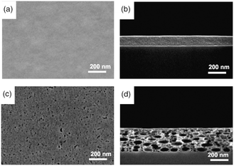 | ||
| Fig. 4 Top view and cross-sectional SEM images of as-printed SnCl4 precursor film before (a and b) and after annealing (c and d) in air at 500 °C for 15 min. Reprinted with permission from Electrochem. Solid-State Lett., 10, K51–K54 (2007). Copyright 2007, The Electrochemical Society.104 | ||
Martínez et al.90 fabricated Mg(OH)2 films on aluminium foils by inkjet printing method for photocatalytic reaction studies. The ink was formulated from magnesium acetate dissolved in NH4OH as precursor, cured by formic acid. Magnesium inks were printed onto the aluminium foil and treated at 200 °C for 5 h. Printing was continued to deposit various layers of Mg(OH)2 denoted as AlMgX, where X is the number of layers. Their study showed that the morphology of Mg(OH)2 layers changed from the smooth surface (X = 1–10) to flake-like particles (X = 20) to porous spherical structures (X = 30), as shown in Fig. 5. Similarly, the specific surface area was calculated to be 4.5, 12.1, 44.3 and 50.2 m2 g−1 for AlMgX layers, where X = 1, 10, 20 and 30, respectively. Accordingly, the most photoactive sample (AlMg30) was made of porous particles with high surface area and roughness. Thus, the formation of porous structures could increase the gas–liquid–solid interactions in the catalyst layers and enhance the photocatalyst performance.90
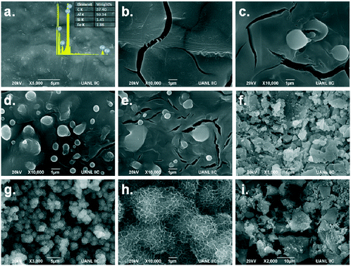 | ||
| Fig. 5 SEM images of AlMgX layers: X = 0 (a), 1 (b), 3 (c), 5 (d), 10 (e), 20 (f), 30 (g and h) and 40 (i). Reprinted with permission from Top. Catal., 15 (2018). Copyright 2018 Springer Nature.90 | ||
4.2 Surface activity
In heterogeneous catalysis, the reaction is literally catalyzed at active sites on the catalyst surface. An active site is an ensemble of atoms or crystal planes which determines the catalyst activity for the specific reaction.105 Aside from that, most of the catalyst surface is catalytically inactive. Therefore, the formation of catalytic active sites should be considered in the ink development stage and deposition of catalytic films via inkjet printing technology. Research on the catalyst active sites is technically challenging and is normally performed by the study of catalytic activity and catalyst material characterizations such as diffraction, spectroscopic methods and chemical adsorption/desorption techniques.106,107 The synthesis approach (e.g., choice of precursors and ligands, pH condition, process temperature and curing time) and post-synthesis treatments such as calcination or sintering play key roles in creating active sites on the catalyst surface.Case in point, Demel et al.92 fabricated ZnO thin films from synthesized ZnO nanosheets on the substrate using dip-coating and inkjet printing methods. ZnO nanosheets were prepared from Zn(OH)2 intercalated with dodecyl sulfate suspended in BuOH. Nanosheets were then dispersed in CHCl3 and BuOH solutions and deposited by using dip-coating and inkjet printing, respectively. The ZnO thin films showed high photocatalytic activity due to the preferentially oriented high-energy {001} plane identified by XRD patterns. They concluded that the large surface area of the ZnO nanosheet {001} planes can be used for catalytic applications. Furthermore, the deposition method affected the film morphology differently. The inkjet-printed layers were rough and porous with the void volume of 60–70%, while the dip-coated layers had relatively smooth and non-porous morphology. The synthesis and deposition process of ZnO nanosheets is illustrated schematically in Fig. 6.
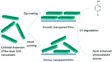 | ||
| Fig. 6 Schematic illustration of deposition of active ZnO nanosheets via dip-coating and inkjet printing for UV degradation reaction. Reprinted with permission from Langmuir. 30, 380–386 (2014). Copyright 2014 American Chemical Society.92 | ||
4.3 Adhesion
A thin-film is normally a fragile structure, and its mechanical properties depend on the underlying substrate and the adhesion between them. Furthermore, the formation and the morphology of thin-films rely on the adhesive forces between the depositing layer and the substrate surface.108 In heterogeneous catalysis, the catalyst materials normally work under dynamic reaction conditions. The fluid (i.e., gas and liquid) flows through the catalyst zone at various velocities under different temperatures and pressures during the reaction cycle. Therefore, the stability of catalyst thin-film should be satisfactory for the operating environment. Thus, the adhesion properties of deposited layers should be considered in the inkjet printing of catalyst materials to deposit robust catalyst thin-films. In addition, adhesion affects the printed layer quality and uniformity as well as its morphology. Generally, the free-standing metal oxide nanoparticles or as-prepared catalyst layers have limited adhesion to the substrate and catalyst immobilization requires to be improved by heat treatment or modification of inkjet ink formulation.109,110 There is no comprehensive quantitative approach to measure adhesion comparatively, and different tests sometimes show contradictory results.111 One conventional technique is using the scratch test for thin-film hardness examination.Černá et al.74 used a hydrothermal synthesis route to prepare titanium dioxide colloidal dispersions in an acidic environment. The dispersion ink solution was printed onto a soda-lime glass substrate, and the deposited films were heated at 500 °C to sinter the TiO2 particles and enhance their adhesion to the glass substrate. They used the “pencil hardness test” to study the hardness of TiO2 thin-films based on the standard ISO 15184.112 Pencils with different hardness were tested using a mechanical device. Accordingly, the TiO2 films were resistant to hardness B while some defects were observed in case of pencil with hardness HB (Fig. 7).
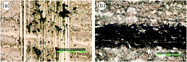 | ||
| Fig. 7 TiO2 thin-films after pencil hardness test: HB pencil hardness test (a) and B pencil hardness test (b). Reprinted from Appl. Catal., B., vol. 138–139, M. Černá, M. Veselý, P. Dzik, C. Guillard, E. Puzenat, M. Lepičová, Fabrication, characterization and photocatalytic activity of TiO2 layers prepared by inkjet printing of stabilized nanocrystalline suspensions, pp. 84–94, Copyright (2013), with permission from Elsevier.74 | ||
The deposited layer adhesion can also be examined during long-term reaction runs or harsh simulated environments. Dittmeyer et al.81,99 used a DOD mode to print alumina nanoparticles in stainless steel microchannels. After the drying and sintering process, the adhesion test was performed in an ultrasonic bath at 25 kHz for 10 min. The coated microchannels were immersed in the ultrasonic bath and the weight loss was monitored. The thin-layers showed less than 10% weight loss, which is satisfactory for typical gas-phase catalytic reactions.113 In another study,97 they printed GaPd2 catalyst into stainless steel microchannels, and the adhesion was examined with sticking tape and dropping from a 30 cm height. Pressurized air was also used to test the layer adhesion. The deposited layers passed all the tests and were stable during the experiments when exposed to gas flow inside the channels. In a recent report, the stability of TiO2 nanolayers printed onto polypropylene substrates was studied in a microreactor for the photodegradation of methylene blue.46 The reaction was conducted for a 48 h continuous run, and almost constant conversion rates were observed. Thus, the printed titania layer was stable under the reaction condition: flow rate = 1 mL h−1; CMB0 (methylene blue concentration in water) = 4 ppm and room temperature.
The ink formulation and the substrate surface properties can also influence the thin-film adhesion and the printed layer properties. The behaviour of ink droplets on the substrate during printing is related to its wetting properties. Wetting shows the affinity of a liquid to maintain contact with a solid substrate caused by intermolecular interactions.114 Ink droplets hit the substrate and go through a dynamic spreading phase over the surface initially driven by kinetic energy (inertial spreading), and then by the wetting of ink on the substrate (capillary spreading and/or recoil). Finally, ink droplets reach thermodynamic equilibrium with the surface and the environment.115 All of these stages are complex and strongly related to the nature of ink, surface and environmental conditions. Among these stages, understanding the equilibrium phase is critical to describe the print quality and the layer adhesion. In addition, developing methods for the measurement of wettability of solid substrates is essential. The droplet equilibrium state on the substrate can be characterized by the contact angle at the liquid–gas–solid interface, which is quantified theoretically by Young equation:116
γSG − γSL − γLG cos![[thin space (1/6-em)]](https://www.rsc.org/images/entities/char_2009.gif) θC = 0 θC = 0 | (5) |
Here, the equilibrium contact angle is denoted by θC, and γSG, γSL and γLG are the solid–gas, the solid–liquid and the liquid–gas interfacial energies, respectively. The contact angle, which is measured as the angle between the tangent to the solid–liquid interface and the tangent to the liquid–gas interface (Fig. 8), quantifies the wettability of a surface.
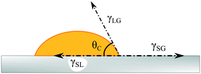 | ||
| Fig. 8 Schematic illustration of a liquid droplet on a substrate showing the drop contact angle based on Young equation. | ||
Practically, the surface wettability and print quality could be enhanced by changing the surface energy (i.e., solid–gas interfacial energy) or the ink surface tension (i.e., liquid–gas interfacial energy). Surface modification is particularly necessary for materials with low surface energies such as polymers. Normally, good wetting occurs for the inks with surface tension (γLG) lower than that of the substrate (γSG). Polymeric substrates have relatively inert surfaces with low surface energies (γSG = 20–50 mN m−1). Therefore, using aqueous-based inks (γLG for H2O ≈ 72 mN −1 at 25 °C) printed onto untreated polymeric substrates may lead to poor wetting.46 In these cases, wettability can be increased by using non-aqueous-based inks with lower surface tensions such as alcohols or improving the substrate surface energy via surface treatment techniques such as plasma-assisted treatments and chemical methods.117 Furthermore, surface treatment methods would activate the substrate and enhance bonding between the substrate and the functional groups within the ink solution. In order to obtain uniform and defect-free printed layers, substrates need to be cleaned thoroughly before surface treatment and printing, using water/alcohols rinse and sonication.
Busato et al.93 deposited patterned palladium catalyst layers onto flexible polyimide film for electroless copper plating by using the inkjet printing method. Prior to printing, polyimide films were treated by wet-chemical method to create a hydrophilic surface receptive to palladium(II) ions. The polyimide film was immersed in 10 M KOH at ambient temperature for 48–72 h then washed with distilled water and dried. The treated films showed about 1.7% weight loss (calculated by gravimetric method) during the surface treatment, which can be ascribed to the oxidative removal from the polyimide surface. Moreover, the contact angle of water droplets was measured to be 21–52° and 66–74° for treated and untreated films, respectively, showing an increase in surface wettability.
Plasma treatment has been used to activate polymeric substrates for inkjet printing of functional metal oxides.46,118 Surface treatment methods such as UV-curable coatings,119 corona discharge,120 and flame treatment121 are also practical alternatives for surface modification of substrates before printing. Furthermore, adhesion promoters such as silane-based chemicals can be used to functionalize dispersed nanoparticles122 or the substrate for enhancing the wetting properties and increasing the affinity of the printed layer to the surface.123
Surface treatment also affects the deposited drop size and printing conditions. Printed droplets on hydrophobic surfaces have smaller size.54 Therefore, surface treatment would make the surface more hydrophilic and enlarge the deposited droplets. On the other hand, the printing speed and the drop spacing depend on the droplet size and should be adjusted to obtain uniform coverage of the surface.118
5 Inkjet printing: features
This section describes the peculiar features of inkjet printing which can be exploited effectively in heterogeneous catalytic processes. These features can be advantageous in the design of catalysts, reactors and comprehensive kinetic studies.5.1 Fast catalytic probe
In catalysis, multi-component metal-oxide catalysts have shown better performance due to the complementary or synergic impacts on the reaction mechanisms.124,125 Mixed-oxide catalysts can assist the reaction in different ways: i) One catalyst component can activate a specific reaction pathway while other components would activate other pathways, ii) double activation catalysts are used for some reactions which require two catalyst components for activation, iii) in some parallel reactions each consecutive reaction is activated by one component of the catalyst and iv) multi-catalyst systems may change the reaction selectivity or hinder the catalyst poisoning.126–128 The catalyst performance (i.e., activity, selectivity and stability) is highly sensitive to its structure, compositional and electronic properties. This fact makes the design of optimal catalysts an arduous challenge. Furthermore, due to the lack of theoretical knowledge about complex catalytic kinetics, a large number of catalysts with different compositions should be synthesized and tested by trial and error to find the most efficient catalyst material.37 Therefore, an optimal multicomponent catalyst for a specific reaction is found through the synthesis and reaction tests of various ratios of metal components which could be a challenging and time-consuming procedure.Several studies have been reported on the generation of catalyst libraries of multi-component catalysts for catalytic reaction explorations.129–132 Among various techniques, inkjet printing has been reported to be a powerful tool for the rapid synthesis of catalyst nanomaterials.94,133,134 Normally the catalyst species precursors are prepared in the form of inks and a variety of composition ratios can be produced by changing the gradient of designed patterns.135
Parkinson et al.67–69,135–137 followed the combinatorial approach to prepare and print metal precursors for the (photo)-electrochemical water-splitting reaction. They studied a variety of precious and non-precious metal combinations from various metal precursors such as metal nitrates, chlorides and organometallic precursors. In these studies, libraries of multi-element catalysts were fabricated on glass substrates using commercial inkjet printers and examined through the water splitting and hydrogen evolution reactions. The screening experiments for gradient compositions of platinum group metals are shown in Fig. 9.
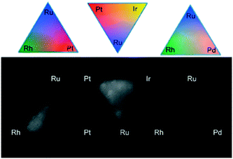 | ||
| Fig. 9 Screening of gradient mixtures of platinum group metals (Pt, Pd, Ru, Rh and Ir) deposited using inkjet printing. Reprinted with permission from ACS Comb. Sci., 15, 82–89 (2013). Copyright 2013 American Chemical Society.69 | ||
Fan et al.86,94,96 developed an inkjet printing synthesis method for the fast optimization of multicomponent mesoporous catalysts. The catalyst libraries were generated at high rates with up to eight-component compositions through the cooperative-assembly method. The inks were prepared using various metal precursors, appropriate block copolymers or surfactants and deposited onto different substrates. They used a modified inkjet printer coupled with a self-developed software package for the high-precision deposition of catalyst layers with specific quantities of ink components. Fig. 10 displays the ternary metal oxides case study including inkjet printing, synthesis and calcination process as well as the strategy used to optimize the catalyst compositions.96
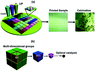 | ||
| Fig. 10 Inkjet printing synthesis and guiding strategy for optimal catalyst exploration. (a) Colloidal ink solutions based on sol–gel chemistry used in a modified inkjet printer. (b) Division of the multi-dimensional space into several groups by the bisection method. Catalytic performance was tested and narrowed down to smaller groups until the optimal catalyst was obtained. Reprinted from ref. 96 with permission from the Royal Society of Chemistry. | ||
5.2 Patterning
In microreactors and gas sensors, the response of the system to target molecules occurs at the catalyst zone. The thermokinetic properties of the process such as the temperature profile and the response time are controlled by the catalyst performance, and the system output is interpreted based on the chemical reactions on the catalyst surface.138,139 In addition, the catalyst location determines where the chemical reaction occurs and where the system response should be detected by a transducer. Therefore, the catalyst material should be locally deposited in the form of patterns on the substrate. Catalyst patterning decreases the amount of catalyst used and hinders the overoxidation and overheating, which results into better heat transfer and mechanical stress distribution at high temperatures. Hence, the catalyst patterning is widely desired in the design of new microsystems.140Two critical factors in developing catalytic microsystems are the choice of catalyst, and the development of a simple method for local deposition of the catalyst close to the transducers. Vapour deposition or magnetron sputtering techniques can be used for patterned thin-film coating. However, the output usually has a non-porous structure, and these methods are not effective for patterning sol–gel-based catalysts, which are typically used in microfluidic systems.142,143 Other alternatives, such as lithography methods, involve time-consuming multistep procedures at high temperatures.21 Inkjet printing can be a promising alternative for local deposition of catalysts due to its mask-free non-contact nature and simple one-step process.
Hu et al.141 fabricated 2D patterns using inkjet printing for the catalytic combustion reaction. This system can be used as a heat source for gas-sensors and micro-electro-mechanical systems (MEMS). Methanol was selected as catalytic combustion fuel and platinum as the heterogeneous catalyst. The Pt-based ink was formulated by dissolving chloroplatinic acid (H2PtCl6) powders into water, and then printed onto heated substrates via a micro-dispensing system in the form of different patterns. Afterwards, the printed patterns were treated under methanol stream at 400 °C, and reduced to Pt catalyst. The catalytic combustion reaction of deposited Pt catalysts was studied in a stainless-steel reactor, and an infrared thermographic camera was used to visualize the temperature profiles of printed platinum patterns (Fig. 11). In this work, the ultra-thin deposition and precise patterning of Pt catalysts could be obtained using inkjet printing.
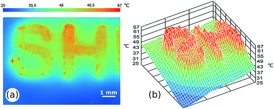 | ||
| Fig. 11 The infrared thermographic image (a) and 3D temperature profile (b) of inkjet-printed Pt catalyst pattern “SH” during the methanol catalytic combustion. Reproduced from J. Power Sources, vol. 271, X. Luo, Z. Zeng, X. Wang, J. Xiao, Z. Gan, H. Wu, Z. Hu, Preparing two-dimensional nano-catalytic combustion patterns using direct inkjet printing, pp. 174–179, Copyright (2014), with permission from Elsevier.141 | ||
Kassem et al.144 used the inkjet printing technique for the fabrication of a fully SnO2-based gas sensor on flexible polyimide foils. All of the sensor components, including a platinum heater, gold electrodes, a polyimide insulating layer, and the SnO2 catalyst layer, were deposited on the top side of the substrate by using a commercial inkjet printing system. The physico-chemical properties of the inks and the printer settings were adjusted to obtain high-resolution printed patterns. An aqueous SnO2-based ink was prepared by sol–gel chemistry and crystallized SnO2 layers could be obtained at 350 °C. Afterwards, the sensor response to different concentrations of gases was examined at 300 °C in dry and wet air conditions. The schematic view of the multilayer flexible SnO2 sensor is shown in Fig. 12.
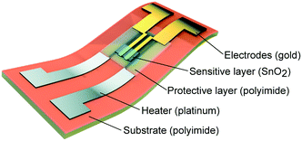 | ||
| Fig. 12 Schematic illustration of flexible SnO2 gas sensor: 3D view of multilayer configurations. Reproduced from ref. 144 with permission from the Royal Society of Chemistry. | ||
Catalyst patterning by inkjet printing has been recently used as an intermediate fabrication step for other applications. Busato93 used the inkjet-printed Pd catalyst patterns on polyimide films for the electroless copper plating process. Beard et al.145 deposited ink solutions of magnetite nanoparticles onto Al2O3 film as a base for the growth of vertically aligned carbon nanotubes (Fig. 13).
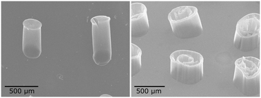 | ||
| Fig. 13 SEM images of vertically aligned carbon nanotubes placed at catalyst sites coated by inkjet printing method. Reproduced with permission from ACS Appl. Mater. Interfaces, 5, 9785–9790 (2013). Copyright 2013 American Chemical Society.145 | ||
5.3 Catalyst support
Solid materials can be used directly as a catalyst; however, more often catalysts are fully dispersed on the surface of a second solid structure called “catalyst support”. Catalyst supports usually have a robust structure with high surface area to maximize the distribution of the catalyst as active material, and increase the catalyst stability. Catalyst supports may participate in the reaction or may be catalytically inert.146 Alumina, carbon and zeolites are typical support materials widely used in the catalysis industry.147 Therefore, synthesis of catalyst support and its loading by active materials are critical steps in the design of catalysts.Inkjet printing may be an efficient approach for the synthesis/deposition of support materials. Catalyst can be added later to the support via impregnation or using inkjet printing again. Dittmeyer et al. applied the inkjet printing technology for deposition of alumina nanoparticles as catalyst support film in microchannels. After layer deposition and calcination, Rh was doped into the support layer by impregnation99 and used in the methane steam reforming reaction.
Inkjet printing could also be utilized to dispense microdroplets on non-planar porous substrates such as mesoporous films and flexible substrates as a support layer. Thus, the effect of supports on the catalyst performance could be studied by high-precision control of the catalyst load. As an example, Hu et al.70 used inkjet printing to deposit a Pt precursor onto Si substrates which were already coated by Al2O3 films. The Pt/Al2O3 catalyst layers were later used in the catalyzed methanol combustion process. Li et al. used inkjet printing for deposition of LiMgMn (ref. 94) and NaMnW (ref. 95) catalysts onto pre-coated La2O3 and SiO2 supports, respectively. The supports were prepared by injection of metal precursors (La(NO3)3 and Si(OC2H5)4) into filter paper by a pipette. The catalyst-based ink formulations were then printed onto the support substrates followed by drying and calcination. The printed catalyst layers were tested in the oxidative coupling of methane reaction.
6 Inkjet printing: case studies
Catalytic systems fabricated by inkjet printing technology have been developed for various applications, ranging from electronic devices to different catalytic reactions. This section reviews the recent applications of inkjet printing in chemical and photochemical reactions involving fluid–solid interactions.6.1 Photocatalysis
Photocatalysis can be used as an efficient approach for the decomposition of complex organic molecules such as dyes and environmental pollutants for air/water treatment.148 For instance, self-cleaning technology provides surfaces which can be cleaned easily by water and can be applied to fabrics and glass for different applications.149 A number of studies have been recently reported on inkjet printing of photoactive materials onto different substrates for photodegradation and self-cleaning applications.The well-known photocatalyst TiO2 is used in several studies for the decomposition of organic pollutants.150 Dzik et al. prepared titania nanoparticle suspensions by various methods (e.g., sol–gel83,85,89 and hydrothermal synthesis74) for inkjet printing of TiO2 layers on glass substrates. The thermally treated layers were then examined to test the photocatalytic activity. For example, the TiO2 nanoparticles synthesized by hydrothermal method at different temperatures and process times exhibited competitive activities for the degradation of 2,6-dichloroindophenol, as shown in Fig. 14.74
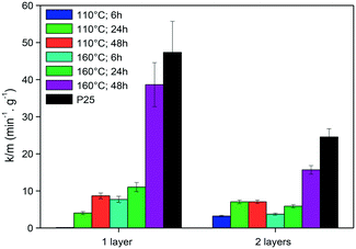 | ||
| Fig. 14 Rate of 2,6-dichloroindophenol decomposition per gram of TiO2 photocatalysts synthesized at different conditions. Reprinted from Appl. Catal., B., vol. 138–139, M. Černá, M. Veselý, P. Dzik, C. Guillard, E. Puzenat, M. Lepičová, Fabrication, characterization and photocatalytic activity of TiO2 layers prepared by inkjet printing of stabilized nanocrystalline suspensions, pp. 84–94, Copyright (2013), with permission from Elsevier.74 | ||
Demel et al.92 used the inkjet printing method for the deposition of ZnO nanosheets on glass supports. Different number of layers were printed and tested for photoactivity based on the degradation of 4-chlorophenol. The printed nanosheets were superior to sol–gel synthesized samples in terms of performance. Furthermore, the photocatalytic activity was enhanced by increasing the layer numbers. The UV/vis spectra of inkjet-printed layers showed sharp absorption edges, common for wide bandgap semiconductors. Furthermore, the thin films were transparent, and the absorption increased linearly with an increase in the number of printed layers (Fig. 15).
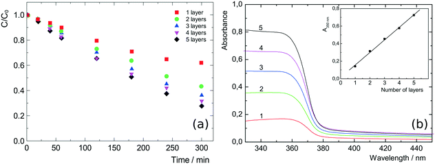 | ||
| Fig. 15 (a) Photodegradation of 4-chlorophenol on printed ZnO films: 1 to 5 layers. Reproduced with permission from Langmuir, 30, 380–386 (2014). Copyright 2014 American Chemical Society. (b) UV/vis absorption spectra of 1 to 5 printed layers of the ZnO nanosheets; inset: absorbance at 350 nm with increasing number of the ZnO layers. Reprinted with permission from the supplementary information of the same reference.92 | ||
Recently, Mg(OH)2 photoactive films were deposited onto aluminium foils via inkjet printing.90 The photocatalyst films were used for the conversion of H2O and CO2 to H2 and CH3OH, respectively. This process as an example of heterogeneous photocatalysis has been utilized for solar fuel production using natural or artificial light as a green alternative to fossil fuels. The printed substrates were placed in a Pyrex tube as a batch reactor for photocatalytic studies. The reactions were carried out at 25 °C and 2 psi under external irradiation provided by two halogen lamps. The reaction products (H2 and CH3OH) were analysed by gas chromatography and UV-vis spectroscopy. Various numbers of Mg(OH)2 layers (1 to 40) were deposited on the Al substrate, and the photocatalytic activity of the reactions was examined. The activity of Mg(OH)2 photocatalyst was attributed to the porous structure of printed films with high surface areas and sufficient pore volumes and roughness, which increased the number of active sites and enhanced the diffusion of gases within the catalyst layers. These performance and structural properties were measured and characterized by kinetic results, scanning electronic microscopy (SEM) and N2 physisorption by BET method.
6.2 Chemical reactions
Several studies have been recently reported on the development of inkjet printing for heterogeneous catalytic reactions inside chemical reactors. Here, the reaction takes place at the solid–fluid interface at different operation conditions, ranging from mild to harsh reaction environments at elevated temperatures and high pressures.Selective catalytic reduction (SCR) is an advanced technology developed for the emission control of industrial boilers, gas turbines and combustion engines in automobiles.151 In a typical SCR process, NOx is converted through a catalytic reaction with gaseous reductants (e.g., NH3, H2 and urea) to N2, H2O and byproducts. Costa et al.98 used the inkjet printing method for the synthesis and deposition of 0.1 wt% Pt/Al2O3 catalyst. Catalyst alternatives with the same compositions were prepared by wet-impregnation, and all of them were examined on the selective catalytic reaction of NO by H2 at the low-temperature range: 100–200 °C. The ink solutions were prepared from metal precursors dissolved in isopropanol with additives such as F127 polymer under an acidic environment and then coated onto a stainless steel substrate. The SCR study was performed in a fixed bed quartz microreactor with 0.05 vol% NO and 1 vol% H2 in the feed stream. The printed catalysts showed superior activity at lower temperature range compared to the wet-impregnated samples. This performance may be due to the synthesis method which leads to a better catalyst morphology (i.e., higher surface area and pore volume) and formation of more active sites.
A combinatorial approach was followed by using inkjet printing technique for the rapid optimization of Cu–Ce–Zr–O mixed oxides for catalytic oxidation of n-hexane.96 Hexane was used as the reactant case as it is a by-product of numerous chemical processes. The inks were prepared by the solution of various ratios of metal precursors in structure-directing agent (SDA), acid and solvent, and printing was performed in a desktop inkjet printer. Fig. 16 shows the uniform morphology of a ternary mesoporous catalyst printed onto the substrate. The kinetic study was performed in a fixed-bed microreactor with 1000 ppm of n-hexane in air stream, and the n-hexane conversion was recorded at 350 °C for all catalyst samples. Finally, the Cu0.32Ce0.28Zr1.00Ox catalyst composite was obtained as the optimal catalyst after probing more than 4000 alternative candidates. Similarly, this procedure could be applied to other gas–solid catalytic systems.
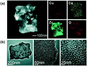 | ||
| Fig. 16 (a) STEM image and elemental mapping of the mixed metal components. (b) TEM images of the mesoporous Cu–Ce–Zr–O structure at different magnifications. Reprinted from ref. 96 with permission from the Royal Society of Chemistry. | ||
Hu et al.88 prepared platinum films for the catalytic combustion of methanol. Chloroplatinic acid (H2PtCl6·6H2O) was used as the metal precursor, and the ink solution was printed onto Si (111) substrate after optimization. The methanol combustion process was examined in a stainless steel reactor, and the temperature profile was analysed by an infrared thermographic camera. This micro-catalytic system could provide heat energy for microsized devices.
A DOD inkjet printing mode was chosen to print GaPd2 nanoparticles as thin, uniform catalyst layers in microchannels for selective hydrogenation of acetylene.97 The catalyst prints were applied using three different approaches: (A) the GaPd2 layer into the bare micro-channels; (B) α-Al2O3 layer followed by a layer of GaPd2 and (C) a layer of GaPd2/α-Al2O3 catalyst. The reaction was then conducted in the micro-channels at 250 °C and feed stream of C2H2/H2/C2H4 in He gas. The catalytic activity and selectivity results are compared with the literature reports in Fig. 17. Accordingly, the printed GaPd2/α-Al2O3 catalyst exhibited the highest catalytic performance and a selectivity of 76% for the semi-hydrogenation of acetylene reaction.
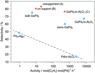 | ||
| Fig. 17 Activity and selectivity of different printing approach A–C and comparison with the literature152 for Pd20Ag80, Pd/α-Al2O3 and GaPd2 bulk as well as nanoparticle samples. Adapted from ref. 97 with permission from John Wiley and Sons. | ||
6.3 Microreactors
The use of inkjet printing can be easily extended to other types of gas/solid and liquid/solid reactions. One potential application would be in microreactor technology. Microreactors have been used to synthesize organic and pharmaceutical compounds,153 and have shown high performance due to high mixing degree, fast heat transfer and better control over the chemical reactions. Therefore, they are practical in laboratory experiments for reaction monitoring and studying kinetic models.154 For fluid/solid reactions, the catalyst requires to be uniformly and precisely immobilized into the microreactor. Therefore, inkjet printing can be helpful in high-precision local deposition of catalysts onto microreactor walls.Dittmeyer et al.81,97,99 performed several studies on the inkjet printing of catalyst-based ink solutions in both semicircular and rectangular microchannels fabricated by wet-chemical etching method and micro-milling, respectively. The ink solutions were printed inside the channels and printing was continued to acquire a specific amount of catalyst. The procedure was followed by drying and calcination, and printed microchannels were obtained. The overall catalyst immobilization process is shown in Fig. 18. The deposited microreactors were then used to study the methane steam reforming99 and hydrogenation of acetylene97 reactions at different reaction conditions. The cross-sectional elemental mapping image of Rh/Al2O3 catalyst onto stainless steel microchannel is shown in Fig. 19. The aluminium and rhodium maps indicate the uniform deposition of catalyst and support zone all over the channel with 13 ± 0.5 μm thickness at the bottom of the channel. The shape of catalyst deposition depends on the rate of solvent evaporation and agglomeration during the drying/calcination process.99
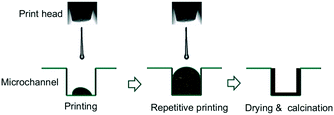 | ||
| Fig. 18 Schematic illustration of deposition of nanoparticle-based inks in microchannels: inkjet printing, drying and calcination process. Reprinted from Appl. Catal., A, vol. 467, S. Lee, T. Boeltken, A. K. Mogalicherla, U. Gerhards, P. Pfeifer, R. Dittmeyer, Inkjet printing of porous nanoparticle-based catalyst layers in microchannel reactors, pp. 69–75, Copyright (2013), with permission from Elsevier.99 | ||
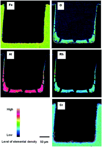 | ||
| Fig. 19 Cross sectional elemental mapping images of Rh/Al2O3 layers printed in a rectangular microchannel. Reprinted from Appl. Catal., A, vol. 467, S. Lee, T. Boeltken, A. K. Mogalicherla, U. Gerhards, P. Pfeifer, R. Dittmeyer, Inkjet printing of porous nanoparticle-based catalyst layers in microchannel reactors, pp. 69–75, Copyright (2013), with permission from Elsevier.99 | ||
Maleki and Bertola46 developed a scalable microreactor made of polypropylene for photocatalytic studies. The microreactor was manufactured by welding a snakelike channel cut out in a black polypropylene sheet, sandwiched between two transparent sheets of the same polymer (PP) by selective transmission laser welding. Fig. 20 shows the different parts of the manufactured microreactor. The black polymeric sheet thickness determines the microchannel thickness which in this case was 700 μm. Before the microreactor fabrication, the transparent polypropylene at the bottom was used as a substrate for deposition of TiO2 nanoparticles in a serpentine pattern. The TiO2 deposition was carried out using a desktop inkjet printer, and the printing process was continued to obtain a film with a well-defined thickness of the catalyst layer. The photocatalytic tests were conducted in the microreactor at ambient pressure and room temperature. Methylene blue was used for the photodegradation studies with an initial concentration of 4 ppm and UV light as the irradiation source. In this study, the manufacturing procedure and inkjet printing were effective in developing flexible lightweight microreactors and deposition of photoactive TiO2 thin-films.
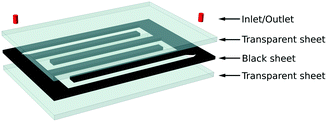 | ||
| Fig. 20 Polypropylene microreactor manufactured by laser welding with specified parts for photocatalytic studies. Available in “TiO2 nanofilms on polymeric substrates for the photocatalytic degradation of methylene blue” under a Creative Commons Attribution 4.0 International Licence. Full terms at https://creativecommons.org/licenses/by/4.0.46 | ||
The inkjet printing technology has been developed for deposition of other types of catalysts such as enzymes and electrocatalysts for the fabrication of sensors,155–157 biodevices158,159 and various electrochemical energy conversion and storage devices160–162 which have been reviewed elsewhere.
7 Challenges and outlooks
Heterogeneous catalysis is a multidisciplinary research area, and the combination of inkjet printing and catalysis should be performed with caution and common sense in order to develop the field without limiting the new possibilities. Furthermore, this combination requires fundamental knowledge of both fields. Despite recent developments, there are still challenges in the integration of the inkjet printing technology within catalytic processes. There are limited records of catalyst-based ink solutions designed for inkjet printing, while a large number of catalysts and catalytic processes exist in the literature. Therefore, further studies are essential to develop novel printable ink formulations with high stability and long storage life, and to broaden our knowledge of ink nano-fluids.The blockage of print-head nozzles is a significant issue in inkjet printing of functional materials. Clogging can be caused by aggregation of dispersed particles, build-up of materials inside the nozzle microchannels or solvent evaporation from the outside. Therefore, the ink solution must be stable, and ink delivery system must become resistant to clogging. Furthermore, the exact drop positioning is uncertain in the current inkjet printing technology mainly due to the drop horizontal velocity and the relative velocity between the nozzle and substrate. Nozzle wetting and contamination and jet-to-jet variations would also lead to deviation of printed patterns from the designed patterns.
To date, few commercial inkjet printers have been adapted for printing metal oxide materials. The current technology is still in lab-scale, with high costs ($5k–50k) and low deposition rates due to the low number of nozzles (1–4) and low drop rates. There are also limitations in controlling substrate and nozzles at high jetting frequencies to enhance the printing resolution and speed. Moreover, the inkjet printing technology should be improved in terms of reliability and lifespan. Current inkjet printers normally have a short lifetime and are not fully reliable for the continuous uniform material printing. Hence, these technical issues should be addressed in the new generations of inkjet printing systems.
Furthermore, inkjet printing has been mostly performed on flat surfaces with hydrophilic properties. Introducing new substrates for catalyst deposition and printing onto curved and irregular surfaces would utilize this technology for heterogeneous catalysis in more complex geometries. Finally, the current inkjet printing technology is limited to the deposition of thin-film structures due to the ink synthesis methods mostly based on sol–gel chemistry. It would be interesting to extend inkjet printing for the fabrication of three-dimensional (3D) structures. One approach is the combination of inkjet printing with other additive manufacturing techniques as integrated systems for the design of heterogeneous catalytic processes.
8 Summary
This work provides an insight into inkjet printing technology in the context of heterogeneous catalysis including a brief introduction and discussion on inkjet synthesis and methods, its potentials and limitations as well as recent developments. Inkjet printing is an emerging attractive material deposition technology for a variety of applications in science and industry due to its efficient, low-cost and scalable nature. Recently this technology has been used in the fabrication and deposition of catalyst materials for catalytic reaction studies. However, it is still in an early stage of development, and there is considerable scope for further growth in inkjet printing for catalysis applications. Furthermore, current challenges such as ink stability and limits to the precursor formulations need to be addressed by improving the understanding of the ink fluid behaviour and of the printing parameters.Conflicts of interest
There are no conflicts to declare.Acknowledgements
The authors acknowledge financial support from the European Regional Development Fund – Low Carbon Eco-Innovatory (LCEI) Project Grant 22R15P00045, in partnership with CAL International Ltd.References
- G. Rothenberg, Catalysis: concepts and green applications, John Wiley & Sons, 2017 Search PubMed.
- J. R. H. Ross, Heterogeneous Catalysis, Elsevier, 2012 Search PubMed.
- E. Santacesaria and R. Tesser, The Chemical Reactor from Laboratory to Industrial Plant, Springer International Publishing, 2018 Search PubMed.
- A. Basile, M. De Falco, G. Centi and G. Iaquaniello, Membrane Reactor Engineering: Applications for a Greener Process Industry, Wiley, 2016 Search PubMed.
- H. de Lasa, Chemical Reactor Design and Technology, Springer Netherlands, 1986 Search PubMed.
- O. Wörz, K.-P. Jäckel, Th. Richter and A. Wolf, Chem. Eng. Technol., 2001, 24, 138–142 CrossRef.
- G. Kolb and V. Hessel, Chem. Eng. J., 2004, 98, 1–38 CrossRef CAS.
- S. Mehla, J. Das, D. Jampaiah, S. Periasamy, A. Nafady and S. K. Bhargava, Catal. Sci. Technol., 2019, 9, 3582–3602 RSC.
- V. Meille, Appl. Catal., A, 2006, 315, 1–17 CrossRef CAS.
- R. Balzarotti, C. Cristiani and L. F. Francis, Catal. Today, 2019, 334, 90–95 CrossRef CAS.
- R. Raja, T. A. Kumar, R. Karthikeyan and G. Balakrishnan, International Journal of Mechanical Engineering and Technology, 2017, 8, 1642–1648 Search PubMed.
- A. I. Kontos, A. G. Kontos, D. S. Tsoukleris, G. D. Vlachos and P. Falaras, Thin Solid Films, 2007, 515, 7370–7375 CrossRef CAS.
- A. Berni, M. Mennig and H. Schmidt, Doctor Blade, Springer, Boston, MA, 2004 Search PubMed.
- J. Bharathan and Y. Yang, Appl. Phys. Lett., 1998, 72, 2660–2662 CrossRef CAS.
- P. Dzik, M. Vesel and J. Chomoucká, J. Adv. Oxid. Technol., 2010, 13, 172–183 CAS.
- L. Quintino, Overview of coating technologies, in Surface Modification by Solid State Processing, Woodhead Publishing Limited, 2014, pp. 1–24, ISBN: 978-0-85709-468-1 Search PubMed.
- D. M. Mattox, Handbook of Physical Vapor Deposition (PVD) Processing, William Andrew, 2010 Search PubMed.
- R. Maric, in Spray-based and CVD Processes for Synthesis of Fuel Cell Catalysts and Thin Catalyst Layers, ed. J. Zhang, Springer London, London, 2008, pp. 917–963 Search PubMed.
- J. Lu, J. W. Elam and P. C. Stair, Surf. Sci. Rep., 2016, 71, 410–472 CrossRef CAS.
- S. J. Won, J. R. Kim, S. Suh, N. I. Lee, C. S. Hwang and H. J. Kim, ACS Appl. Mater. Interfaces, 2011, 3, 1633–1639 CrossRef CAS PubMed.
- N. C. Raut and K. Al-Shamery, J. Mater. Chem. C, 2018, 6, 1618–1641 RSC.
- Y. Aleeva and B. Pignataro, J. Mater. Chem. C, 2014, 2, 6436–6453 RSC.
- M. Singh, H. M. Haverinen, P. Dhagat and G. E. Jabbour, Adv. Mater., 2010, 22, 673–685 CrossRef CAS PubMed.
- N. Scoutaris, M. R. Alexander, P. R. Gellert and C. J. Roberts, J. Controlled Release, 2011, 156, 179–185 CrossRef CAS PubMed.
- A. C. Fischer, M. Mäntysalo and F. Niklaus, Handb. Silicon Based MEMS Mater. Technol., Elsevier, 2nd edn 2015, pp. 550–564 Search PubMed.
- K. Pataky, V. Auzelyte and J. Brugger, Inkjet printing for MEMS, Wiley-VCH Verlag, 2012 Search PubMed.
- V. Lindroos, A. Lehto, T. Motooka and M. Tilli, Handbook of Silicon Based MEMS Materials and Technologies, 2010 Search PubMed.
- M. M. Mohebi and J. R. G. Evans, J. Comb. Chem., 2019, 4, 267–274 CrossRef PubMed.
- Inkjet Technology for Digital Fabrication, ed. I. M. Hutchings and G. D. Martin, John Wiley & Sons, Ltd, Chichester, UK, 2012 Search PubMed.
- Z. P. Yin, Y. A. Huang, N. B. Bu, X. M. Wang and Y. L. Xiong, Chin. Sci. Bull., 2010, 55, 3383–3407 CrossRef.
- A. Atala and J. J. Yoo, Essentials of 3D Biofabrication and Translation, Elsevier, Academic Press, 2015 Search PubMed.
- B.-J. de Gans, P. C. Duineveld and U. S. Schubert, Adv. Mater., 2004, 16, 203–213 CrossRef CAS.
- J. Moon and K. Song, Inkjet printing of metal oxide thin-film transistors, Wiley-VCH Verlag, 2012, pp. 237–255 Search PubMed.
- K. J. Baeg and Y. Y. Noh, Large Area and Flexible Electronics, Wiley-VCH Verlag GmbH & Co. KGaA, Weinheim, Germany, 2015, pp. 345–364 Search PubMed.
- J. Turner, H. C. Aspinall, S. Rushworth and K. Black, RSC Adv., 2019, 9, 39143–39146 RSC.
- J. Perelaer, P. J. Smith, D. Mager, D. Soltman, S. K. Volkman, V. Subramanian, J. G. Korvink and U. S. Schubert, J. Mater. Chem., 2010, 20, 8446–8453 RSC.
- X. Liu, T.-J. Tarn, F. Huang and J. Fan, Particuology, 2015, 19, 1–13 CrossRef CAS.
- A. Kamyshny, Open Appl. Phys. J., 2011, 4, 19–36 CrossRef CAS.
- S. Wünscher, R. Abbel, J. Perelaer and U. S. Schubert, J. Mater. Chem. C, 2014, 2, 10232–10261 RSC.
- C.-T. Chen, Features of Liquid Crystal Display Materials and Processes, IntechOpen, Rijeka, 2011, ch. 3 Search PubMed.
- C. Hurt, M. Brandt, S. S. Priya, T. Bhatelia, J. Patel, P. R. Selvakannan and S. Bhargava, Catal. Sci. Technol., 2017, 7, 3421–3439 RSC.
- P. B. Meggs and A. W. Purvis, Meggs' History of Graphic Design, 6th Edition, Wiley, 2016 Search PubMed.
- H. W. Vollmann, Angew. Chem., Int. Ed. Engl., 1980, 19, 99–110 CrossRef.
- S. M. F. Cruz, L. A. Rocha and J. C. Viana, Flexible Electronics, IntechOpen, Rijeka, 2018 Search PubMed.
- K. K. B. Hon, L. Li and I. M. Hutchings, CIRP Ann., 2008, 57, 601–620 CrossRef.
- H. Maleki and V. Bertola, ACS Appl. Nano Mater., 2019, 2, 7237–7244 CrossRef CAS.
- H. Sirringhaus and T. Shimoda, MRS Bull., 2003, 28, 802–806 CrossRef.
- H. Jiang and H. Tan, Fluids, 2019, 3, 28–51 CrossRef.
- G. D. Martin, S. D. Hoath and I. M. Hutchings, J. Phys.: Conf. Ser., 2008, 105, 012001–012016 CrossRef.
- M. Addamo, V. Augugliaro, A. Di Paola, E. García-López, V. Loddo, G. Marcí, R. Molinari, L. Palmisano and M. Schiavello, J. Phys. Chem. B, 2004, 108, 3303–3310 CrossRef CAS.
- P. Sundriyal and S. Bhattacharya, ACS Appl. Mater. Interfaces, 2017, 9, 38507–38521 CrossRef CAS PubMed.
- G. Cummins and M. P. Y. Desmulliez, Circuit World, 2012, 38, 193–213 CrossRef CAS.
- R. Waasdorp, O. van den Heuvel, F. Versluis, B. Hajee and M. K. Ghatkesar, RSC Adv., 2018, 8, 14765–14774 RSC.
- I. M. Mahbubul, R. Saidur and M. A. Amalina, Int. J. Heat Mass Transfer, 2012, 55, 874–885 CrossRef CAS.
- S. Mueller, E. W. Llewellin and H. M. Mader, Proc. R. Soc. A, 2010, 466, 1201–1228 CAS.
- N. Reis and B. Derby, Mater. Res. Soc. Symp. Proc., 2000, 65–70 CrossRef.
- B. Derby, Annu. Rev. Mater. Res., 2010, 40, 395–414 CrossRef CAS.
- C. D. Stow and M. G. Hadfield, Proc. R. Soc. A, 1981, 373, 419–441 Search PubMed.
- P. C. Duineveld, M. M. de Kok, M. Buechel, A. Sempel, K. A. H. Mutsaers, P. van de Weijer, I. G. J. Camps, T. van de Biggelaar, J.-E. J. M. Rubingh and E. I. Haskal, Organic Light-Emitting Materials and Devices V, 2002, pp. 59–67 Search PubMed.
- S. Magdassi, The Chemistry of Inkjet Inks, World Scientific, 2009 Search PubMed.
- A. Kamyshny and S. Magdassi, Inkjet-based Micromanufacturing, John Wiley & Sons, Ltd, 2012, pp. 173–189 Search PubMed.
- L. Nayak, S. Mohanty, S. K. Nayak and A. Ramadoss, J. Mater. Chem. C, 2019, 7, 8771–8795 RSC.
- B. Derby, J. Eur. Ceram. Soc., 2011, 31, 2543–2550 CrossRef CAS.
- M. Dondi, M. Blosi, D. Gardini and C. Zanelli, CFI, Ceram. Forum Int., 2012, 89, E59–E64 CAS.
- J. Feys, P. Vermeir, P. Lommens, S. C. Hopkins, X. Granados, B. A. Glowacki, M. Baecker, E. Reich, S. Ricard, B. Holzapfel, P. Van Der Voort and I. Van Driessche, J. Mater. Chem., 2012, 22, 3717–3726 RSC.
- J. S. Gebauer, V. Mackert, S. Ognjanović and M. Winterer, J. Colloid Interface Sci., 2018, 526, 400–409 CrossRef CAS PubMed.
- I. Rodríguez-Gutiérrez, R. García-Rodríguez, M. Rodríguez-Pérez, A. Vega-Poot, G. Rodríguez Gattorno, B. A. Parkinson and G. Oskam, J. Phys. Chem. C, 2018, 122, 27169–27179 CrossRef.
- K. Skorupska, P. A. Maggard, R. Eichberger, K. Schwarzburg, P. Shahbazi, B. Zoellner and B. A. Parkinson, ACS Comb. Sci., 2015, 17, 742–751 CrossRef CAS PubMed.
- D. Seley, K. Ayers and B. A. Parkinson, ACS Comb. Sci., 2013, 15, 82–89 CrossRef CAS PubMed.
- T. Liu, Z. Zeng, X. Wang, X. Yan and Z. Hu, Adv. Mater. Res., 2012, 550–553, 257–260 CAS.
- C. Costa, C. Pinheiro, I. Henriques and C. A. Laia, ACS Appl. Mater. Interfaces, 2012, 4, 1330–1340 CrossRef CAS PubMed.
- A. Matavž, R. C. FrunzA, A. Drnovšek, V. Bobnar and B. Malič, J. Mater. Chem. C, 2016, 4, 5634–5641 RSC.
- M. Arin, P. Lommens, S. C. Hopkins, G. Pollefeyt, J. Van Der Eycken, S. Ricart, X. Granados, B. A. Glowacki and I. Van Driessche, Nanotechnology, 2012, 23, 165603–165613 CrossRef PubMed.
- M. Černá, M. Veselý, P. Dzik, C. Guillard, E. Puzenat and M. Lepičová, Appl. Catal., A, 2013, 138–139, 84–94 CrossRef.
- R. Dou, T. Wang, Y. Guo and B. Derby, J. Am. Ceram. Soc., 2011, 94, 3787–3792 CrossRef CAS.
- D. Kuscer, G. Stavber, G. Trefalt and M. Kosec, J. Am. Ceram. Soc., 2012, 95, 487–493 CrossRef CAS.
- I. M. Krieger and T. J. Dougherty, Trans. Soc. Rheol., 1959, 3, 137–152 CAS.
- D. B. Genovese, Adv. Colloid Interface Sci., 2012, 171-172, 1–16 CrossRef CAS PubMed.
- C. Servais, R. Jones and I. Roberts, J. Food Eng., 2002, 51, 201–208 CrossRef.
- K. Qin and A. A. Zaman, J. Colloid Interface Sci., 2003, 266, 461–467 CrossRef CAS.
- A. K. Mogalicherla, S. Lee, P. Pfeifer and R. Dittmeyer, Microfluid. Nanofluid., 2014, 16, 655–666 CrossRef CAS.
- T. Tanaka, K. Kadota, Y. Tozuka, A. Shimosaka and Y. Shirakawa, Ceram. Int., 2016, 42, 9963–9971 CrossRef CAS.
- M. Arin, P. Lommens, N. Avci, S. C. Hopkins, K. De Buysser, I. M. Arabatzis, I. Fasaki, D. Poelman and I. Van Driessche, J. Eur. Ceram. Soc., 2011, 31, 1067–1074 CrossRef CAS.
- P. Dzik, M. Morozová, P. Kluson and M. Veselý, J. Adv. Oxid. Technol., 2012, 15, 89–97 CAS.
- M. Černá, M. Veselý and P. Dzik, Catal. Today, 2011, 161, 97–104 CrossRef.
- X. Liu, Y. Shen, R. Yang, S. Zou, X. Ji, L. Shi, Y. Zhang, D. Liu, L. Xiao, X. Zheng, S. Li, J. Fan and G. D. Stucky, Nano Lett., 2012, 12, 5733–5739 CrossRef CAS PubMed.
- M. Arin, J. Watté, G. Pollefeyt, K. De Buysser, I. Van Driessche and P. Lommens, J. Sol-Gel Sci. Technol., 2013, 66, 100–111 CrossRef CAS.
- J. Xiao, X. Wang, X. Luo and Z. Hu, Appl. Surf. Sci., 2015, 327, 400–405 CrossRef CAS.
- M. Morozova, P. Kluson, J. Krysa, P. Dzik, M. Vesely and O. Solcova, Sens. Actuators, B, 2011, 160, 371–378 CrossRef CAS.
- E. Luévano-Hipólito and L. M. Torres Martínez, Top. Catal., 2018, 61, 1574–1584 CrossRef.
- E. Luévano-Hipólito, L. M. Torres-Martínez, C. Triana and S. W. Lee, Thin Solid Films, 2019, 677, 83–89 CrossRef.
- J. Hynek, V. Kalousek, R. Žouželka, P. Bezdička, P. Dzik, J. Rathouský, J. Demel and K. Lang, Langmuir, 2014, 30, 380–386 CrossRef CAS PubMed.
- S. Busato, A. Belloli and P. Ermanni, Sens. Actuators, B, 2007, 123, 840–846 CrossRef CAS.
- Z. Li, L. He, S. Wang, W. Yi, S. Zou, L. Xiao and J. Fan, ACS Comb. Sci., 2017, 19, 15–24 CrossRef CAS PubMed.
- Z. Li, S. Wang, W. Hong, S. Zou, L. Xiao and J. Fan, ChemNanoMat, 2018, 4, 487–495 CrossRef CAS.
- F. Huang, S. Wang, W. Yi, S. Zou, C. Chen, L. Xiao, X. Liu and J. Fan, Chem. Commun., 2015, 51, 8157–8160 RSC.
- M. Siebert, R. R. Zimmermann, M. Armbrüster and R. Dittmeyer, ChemCatChem, 2017, 9, 3733–3742 CrossRef CAS.
- V. K. Chatziiona, B. K. Constantinou, P. G. Savva, G. G. Olympiou, K. Kapnisis, A. Anayiotos and C. N. Costa, Catal. Commun., 2018, 103, 69–73 CrossRef CAS.
- S. Lee, T. Boeltken, A. K. Mogalicherla, U. Gerhards, P. Pfeifer and R. Dittmeyer, Appl. Catal., A, 2013, 467, 69–75 CrossRef CAS.
- M. Kralova, P. Dzik, M. Vesely and J. Cihlar, Catal. Today, 2014, 230, 188–196 CrossRef CAS.
- T. T. N. Nguyen, Y. H. Chen and J. L. He, Thin Solid Films, 2014, 572, 8–14 CrossRef CAS.
- J. Yu, X. Zhao, Q. Zhao and G. Wang, Mater. Chem. Phys., 2001, 68, 253–259 CrossRef CAS.
- C. Seo, D. Jang, J. Chae and S. Shin, Sci. Rep., 2017, 7, 500 CrossRef PubMed.
- D. H. Lee, Y. J. Chang, W. Stickle and C. H. Chang, Electrochem. Solid-State Lett., 2007, 10, 51–54 CrossRef.
- J. P. Greeley, Science, 2012, 336, 810–811 CrossRef PubMed.
- J. Greeley, J. K. Nørskov and M. Mavrikakis, Annu. Rev. Phys. Chem., 2002, 53, 319–348 CrossRef CAS PubMed.
- K. Honkala, A. Hellman, I. Remediakis, A. Logadottir, A. Carlsson, S. Dahl, C. H. Christensen and J. K. Nørskov, Science, 2005, 307, 555–558 CrossRef CAS PubMed.
- M. El-Shabasy, Periodica Polytechnica Electrical Engineering and Computer Science, 1981, 25, 123–134 Search PubMed.
- H. Shibata, H. Sakai, P. Rangsunvigit, T. Hirano and M. Abe, Surf. Coat. Int., Part B, 2003, 86, 125–130 CrossRef CAS.
- B. C. Enger, J. Walmsley, E. Bjørgum, R. Lødeng, P. Pfeifer, K. Schubert, A. Holmen and H. J. Venvik, Chem. Eng. J., 2008, 144, 489–501 CrossRef CAS.
- S. Franssila, Introduction to Microfabrication, John Wiley & Sons, 2010 Search PubMed.
- A. Kundu, in Aircraft Design, Cambridge Aerospace Series, Cambridge: Cambridge University Press, 2012, pp. 577–578, DOI:10.1017/CBO9780511844652.021.
- N. R. Peela, A. Mubayi and D. Kunzru, Catal. Today, 2009, 147, S17–S23 CrossRef CAS.
- K.-Y. Law and H. Zhao, Surface wetting: characterization, contact angle, and fundamentals, Springer, Switzerland, 2016 Search PubMed.
- R. A. Dorey, Ceramic Thick Films for MEMS and Microdevices, William Andrew, 2012 Search PubMed.
- T. Young, Philos. Trans. R. Soc. London, 1805, 65–87 Search PubMed.
- P. Fabbri and M. Messori, Modif. Polym. Prop., 2017, pp. 109–130 Search PubMed.
- M. Rieu, M. Camara, G. Tournier, J. P. Viricelle, C. Pijolat, N. F. de Rooij and D. Briand, Sens. Actuators, B, 2016, 236, 1091–1097 CrossRef CAS.
- I. Bhattacharya, Polym. Paint Colour J., 2006, 196, 16–19 CAS.
- S. Brzezinski, M. Zenkiewicz, S. Polowinski, D. Kowalczyk, I. Karbownik, S. Lutomirski and G. Malinowska, Polimery, 2009, 54, 421–429 CrossRef CAS.
- S. Farris, S. Pozzoli, P. Biagioni, L. Duó, S. Mancinelli and L. Piergiovanni, Polymer, 2010, 51, 3591–3605 CrossRef CAS.
- Y. Treekamol, D. Lehmann, M. Schieda, I. Herrmann-Geppert and T. Klassen, MRS Online Proc. Libr., 2015, 1776, 13–17 CrossRef.
- M. D. Z. H. Khan, Cogent Eng., 2016, 3, 1170097–1170115 Search PubMed.
- M. Misono, Catalysis of perovskite and related mixed oxides, Elsevier Science, 2013, vol. 176, pp. 67–95 Search PubMed.
- X. Fang and L. Wu, Handbook of innovative nanomaterials: From syntheses to applications, Pan Stanford Pub., 2012, pp. 1–921 Search PubMed.
- G. F. Swiegers, Mechanical Catalysis: Methods of Enzymatic, Homogeneous, and Heterogeneous Catalysis, John Wiley, 2008, pp. 1–351 Search PubMed.
- S. Belot, K. A. Vogt, C. Besnard, N. Krause and A. Alexakis, Angew. Chem., Int. Ed., 2009, 48, 8923–8926 CrossRef CAS PubMed.
- H. Xu, S. J. Zuend, M. G. Woll, Y. Tao and E. N. Jacobsen, Science, 2010, 327, 986–990 CrossRef CAS PubMed.
- F. A. Castillo, J. Sweeney, P. Margl and W. Zirk, QSAR Comb. Sci., 2005, 24, 38–44 CrossRef CAS.
- J. Klein, T. Zech, J. M. Newsam and S. A. Schunk, Appl. Catal., A, 2003, 254, 121–131 CrossRef CAS.
- S. Senkan, Angew. Chem., Int. Ed., 2001, 40, 312–329 CrossRef CAS.
- Y. Yang, T. Lin, X. L. Weng, J. A. Darr and X. Z. Wang, Comput. Chem. Eng., 2011, 35, 671–678 CrossRef CAS.
- M. Woodhouse, G. S. Herman and B. A. Parkinson, Chem. Mater., 2005, 17, 4318–4324 CrossRef CAS.
- J. R. Evans, M. J. Edirisinghe, P. V. Coveney and J. Eames, J. Eur. Ceram. Soc., 2001, 21, 2291–2299 CrossRef CAS.
- M. Woodhouse and B. A. Parkinson, Chem. Mater., 2008, 20, 2495–2502 CrossRef CAS.
- K. Skorupska and B. A. Parkinson, in Combinatorial Synthesis and Screening of Oxide Materials for Photoelectrochemical Energy Conversion, ed. S. Giménez and J. Bisquert, Springer International Publishing, Cham, 2016, pp. 427–462 Search PubMed.
- J. G. Rowley, T. D. Do, D. A. Cleary and B. A. Parkinson, ACS Appl. Mater. Interfaces, 2014, 6, 9046–9052 CrossRef CAS PubMed.
- E. Vereshchagina, R. A. M. Wolters and J. G. E. Gardeniers, Sens. Actuators, A, 2011, 169, 308–316 CrossRef CAS.
- K. D. Nagy and K. F. Jensen, Chim. Oggi, 2011, 29, 18–21 CAS.
- E. Vereshchagina, O. Bliznyuk, R. M. Tiggelaar, K. Altena-Schildkamp and J. G. E. Gardeniers, J. Micromech. Microeng., 2012, 22, 045023 CrossRef.
- X. Luo, Z. Zeng, X. Wang, J. Xiao, Z. Gan, H. Wu and Z. Hu, J. Power Sources, 2014, 271, 174–179 CrossRef CAS.
- H. L. Tuller and R. Mlcak, J. Electroceram., 2000, 4, 415–425 CrossRef CAS.
- M. Roumanie, C. Pijolat, V. Meille, C. De Bellefon, P. Pouteau and C. Delattre, Sens. Actuators, B, 2006, 118, 297–304 CrossRef CAS.
- O. Kassem, M. Saadaoui, M. Rieu and J. P. Viricelle, J. Mater. Chem. C, 2019, 7, 12343–12353 RSC.
- J. D. Beard, J. Stringer, O. R. Ghita and P. J. Smith, ACS Appl. Mater. Interfaces, 2013, 5, 9785–9790 CrossRef CAS PubMed.
- H. S. Taylor, Proc. R. Soc. A, 1925, 108, 105–111 CAS.
- Z. Ma and F. Zaera, in Heterogeneous Catalysis by Metals, American Cancer Society, 2014, pp. 1–16 Search PubMed.
- J. Trawiński and R. Skibiński, Environ. Sci. Pollut. Res., 2017, 24, 1152–1199 CrossRef PubMed.
- J. Watté, P. Lommens, G. Pollefeyt, M. Meire, K. De Buysser and I. Van Driessche, ACS Appl. Mater. Interfaces, 2016, 8, 13027–13036 CrossRef PubMed.
- A. Fujishima, T. N. Rao and D. A. Tryk, J. Photochem. Photobiol., C, 2000, 1, 1–21 CrossRef CAS.
- K. C. Taylor, Stud. Surf. Sci. Catal., 1987, 30, 97–116 CrossRef CAS.
- M. Armbrüster, R. Schlögl and Y. Grin, Sci. Technol. Adv. Mater., 2014, 15, 034803–034821 CrossRef PubMed.
- M. Veeramani, S. Narasimhan and N. Bhatt, Comput.-Aided Chem. Eng., 2018, 44, 931–936 CAS.
- J. S. Moore, C. D. Smith and K. F. Jensen, React. Chem. Eng., 2016, 1, 272–279 RSC.
- R. P. Tortorich, H. Shamkhalichenar and J. W. Choi, Appl. Sci., 2018, 8, 288–304 CrossRef.
- A. Al-Halhouli, H. Qitouqa, A. Alashqar and J. Abu-Khalaf, Sens. Rev., 2018, 38, 438–452 CrossRef.
- A. Moya, G. Gabriel, R. Villa and F. Javier del Campo, Curr. Opin. Electrochem., 2017, 3, 29–39 CrossRef CAS.
- L. Gonzalez-Macia, A. Morrin, M. R. Smyth and A. J. Killard, Analyst, 2010, 135, 845–867 RSC.
- A. Othman, A. Karimi and S. Andreescu, J. Mater. Chem. B, 2016, 4, 7178–7203 RSC.
- S. Ganesan, S. Mehta and D. Gupta, Opto-Electron. Rev., 2019, 27, 298–320 CrossRef.
- A. Lesch, F. Cortés-Salazar, V. C. Bassetto, V. Amstutz and H. H. Girault, Chimia, 2015, 69, 284–289 CrossRef CAS PubMed.
- L. J. Deiner and T. L. Reitz, Adv. Eng. Mater., 2017, 19, 1600878–1600896 CrossRef.
| This journal is © The Royal Society of Chemistry 2020 |

