Function-oriented synthesis of two-dimensional (2D) covalent organic frameworks – from 3D solids to 2D sheets
Xing
Li
 ,
Priya
Yadav
and
Kian Ping
Loh
 *
*
Department of Chemistry, National University of Singapore, Singapore 117543, Singapore. E-mail: chmlohkp@nus.edu.sg
First published on 3rd June 2020
Abstract
Covalent organic frameworks (COFs) are constructed from the precise integration of small organic blocks into an extended, porous framework via covalent linkages. COFs can also be viewed as an organic solid consisting of a periodic array of one dimensional (1-D) channels. Although a wide range of applications have been envisioned for COFs, understanding the structure–property correlation at the level of chemical linkages, topology, pore size and functionality is needed to unlock the potential of these materials. Herein, we review some emerging applications of two-dimensional (2D) COFs in solid-state photoluminescence, stimuli-responsive COFs, gas storage, ion conduction and energy storage, and discuss the intricate design principles that enable these COFs to perform better than their building blocks or polymeric counterparts. Going beyond bulk 2D-COFs, molecular thin organic layers called COFene can be derived from the exfoliation of 2D COFs, generating new properties for applications in optoelectronic devices, catalysis and separation.
1. Introduction
Although organic molecules can be synthesized with bond-to-bond, atom-to-atom precision, the cross-linking of these molecules to form a periodic framework in three-dimensional space has to compete with the fast rate of random polymerization. The synthesis of crystalline organic–inorganic polymeric materials such as zeolites,1,2 perovskites,3,4 and metal organic frameworks (MOFs)5,6 has seen tremendous progress over the past few decades. Progress in the synthesis of crystalline porous organic polymers reached a milestone with the discovery of covalent organic frameworks (COFs) in 2005 by Yaghi.7–14 The focus in COF research thus far has been heavily focused on synthesizing structures with different topologies and covalent linkages, improving crystallinity or performing various post-synthetic modifications. The ease of encoding functionalities and the abundant choice of building units and linkages give rise to a plethora of COFs with diverse properties. Despite this, a unique application that differentiates COFs from their molecular fragments or polymers has yet to be identified. This is not helped by the fact that the single-crystal structures of most COFs synthesized to date are still not confirmed. Besides the need to continually improve the crystallinity of COFs, researchers should leverage the rigid framework structures and uniform pore structures in COFs to obtain performance that is larger than the sum of their parts.Eschenmoser introduced the concept of “functional-oriented synthesis” thirty years ago; this is underscored by the concept that nature-evolved molecules are more complicated than the function encoded in them.15 Understanding structure–property correlations allows chemists to simplify the design of these molecules to perform the same function, or achieve even better performance. For instance, synthetic fentanyl has a less complicated structure and stronger biological activity than natural morphine.16 However, the concept of function-oriented synthesis is still mainly restricted to the synthesis of small molecules and has not been applied to the synthesis of framework structures.
To develop performance differentiations in COFs, chemists need to leverage the intrinsic characteristics of COFs such as their rigid framework structures, stacking order and 1-D channels, and install requisite functional groups to create synergistic interactions. In this review, we will focus on how different elements of COFs, such as their topology, chemical linkages, stacking order and porosity, can be optimized to achieve competitive performance in applications such as light emission, stimuli response, gas storage, ion conduction, and energy storage. A summary on the properties of 2D COFs and how they can be exploited for different applications is shown in Table 1.
| Properties | Applications | Role of 2D COFs | Advantages | Disadvantages |
|---|---|---|---|---|
| Light emission | • Sensing | 1. A metal-free crystalline platform for integration of functionalities | 1. Metal-free | 1. Relatively low quantum efficiency |
| • Photocatalysis | 2. Inducing synergistic interactions of functions encoded | 2. Predictable ordered structures | 2. Processability | |
| • Bioimaging | 3. Providing high surface area | 3. Ease of encoding luminogens | ||
| • Lighting | 4. Linkage-dependant stability | |||
| 5. Tunable optical bandgaps | ||||
| 6. Unusual molecular packing | ||||
| 7. Porosity | ||||
| Solvato-chromism | • Sensing | 1. Low energy cost for tautomerization | 1. Processability | |
| • Catalysis | 2. High sensitivity to guest molecules | |||
| • Non-linear optics | 3. Tunable electronic and optical bandgaps | |||
| • Lighting | 4. Feasible synthesis | |||
| Redox | • Energy storage | 1. Stabilizing redox species from dissolution | 1. Enhanced stability of the electrode | 1. Poor electrical conductivity |
| • Battery electrodes | 2. Providing ordered channels for ion diffusion | 2. Facilitated ion transport | 2. Relatively low energy density due to the porous structures | |
| • Pseudocapacitors | 3. Providing high surface area for increasing capacitance | 3. Large surface area for improving capacitance | ||
| 4. Improving pseudocapacitance via redox species | ||||
| Host–guest chemistry | • Gas storage | 1. Providing free volume for containing guest molecules | 1. Metal-free, low toxicity, environment friendly | 1. Poor electrical conductivity |
| • Separation | 2. Providing specific binding sites | 2. Ease of encoding functionalities for enhancing selective binding either from pre- or post-synthetic modification | 2. More defects compared to single crystalline materials | |
| • Drug delivery | 3. Offering size selectivity to guest molecules | 3. High surface area | ||
| • Size-selective catalysis | 4. Linkage-dependent stability | |||
| • Supercapacitors | ||||
| • Metal–sulfur batteries | ||||
| • Metal–gas batteries | ||||
| Ion conduction | • Solid-state electrolytes | 1. Tailor-made 1D channels for ion diffusion | 1. Facilitated ion transport | 1. Processability |
| • Battery separators | 2. Eliminating phase transition of the materials upon proper design | 2. Interface issues with electrodes | ||
| • Battery electrodes | 3. Ease of structure modification for improving ion diffusion | 3. Flammability |
Two-dimensional (2D) COFs are called “2D” because the covalent linkages are in-plane while the non-covalent interactions between different planes are in the out-of-plane direction. Therefore, similar to graphite, bulk 2D COFs are actually quasi-2D materials and they can become truly 2D only when reduced to the thickness of a single or a few unit cells. The relatively weak bonding along the z-axis allows 2D COFs to be delaminated into few-layer thin sheets that can have better solution-processability compared to three-dimensional (3D) COFs. Moreover, bulk 2D COFs17–19 can act as templates for the synthesis of crystalline 2D polymers.20,21 Inspired by breakthroughs in 2D materials, the synthesis of ultrathin 2D COF sheets has become an emerging field.22–26 Akin to graphene27 and MXenes,28 the name COFene11 has been coined for ultrathin 2D COF sheets, which are believed to have properties distinct to bulk COFs and conventional 2D materials such as graphene and transition metal dichalcogenides.
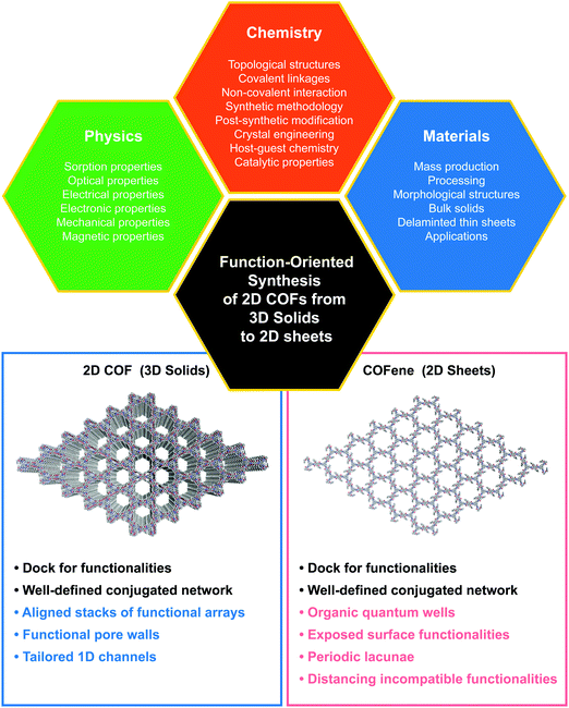 | ||
| Fig. 1 The trinity of function-oriented synthesis of bulk 2D COFs and few-layer COFs, named COFenes. | ||
This article discusses the structure–property correlations for function-oriented design and synthesis of COFs from the bulk to an ultrathin level (Fig. 1). COF structures are analyzed by deconstructing them into backbone functionalities, linkages, and topological nets, so that we can understand how these components act either singly or in concert to attain particular properties and functions.
2. Function-oriented synthesis of 2D COFs
In this section, we will highlight recent advances in the potential applications of 2D COFs, which include solid-state light emission, stimuli-responsive COFs, CO2 capture and conversion, and ion conduction. The roles of molecular scaffolds and covalent linkages in enhancing the performance are discussed.2.1 Solid-state emission
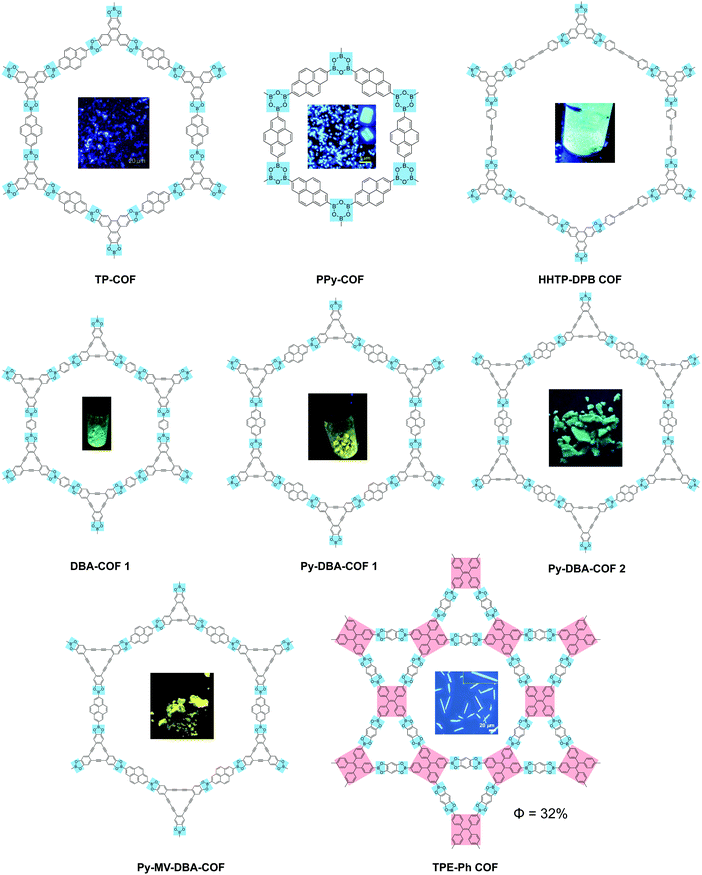
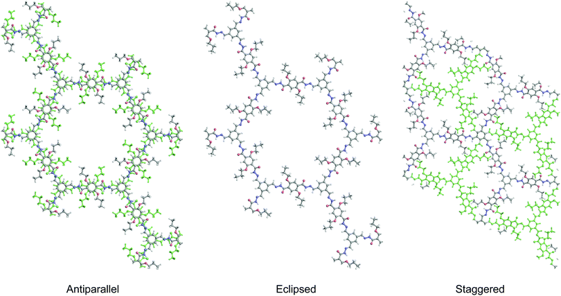
2D COFs provide a framework in the form of an anisotropic, crystalline organic 2D material for understanding the photo-physics of photon and charge interactions, where exciton and charge transport in the in-plane and out-of-plane directions are expected to be different. It is expected that different stacking orders such as eclipsed, staggered or antiparallel will exert distinct influence on the optical and electronic properties. The presence of porosity suggests that the pores and channels can be used for host–guest interactions; in addition, donor–acceptor interactions can be used to tune the fluorescence.Many 2D COFs that are built from luminescent building blocks suffer from fluorescence quenching. Aggregation-induced quenching by π–π stacking does not account entirely for the quenching because COFs built from the same molecular building block can be fluorescent or non-fluorescent depending on whether the linkages are boronic ester type linkages or imine type.29–32 Compared to the mechanically stiffer (but chemically unstable) boronic ester linkages, imine-type linkages are rotationally labile when photo-excited, which may result in de-excitation via non-emissive dissipative pathways. In this section, we will review selected fluorescent 2D COFs and discuss the structural design used to turn on the solid-state light emission in 2D COFs (Table 2).
| 2D COF | Emission λmax (nm) | Φ PL (%) | Covalent linkage | Ref. |
|---|---|---|---|---|
| TP-COF | 474 | — | Boronate | 32 |
| PPy-COF | 484 | — | Boroxine | 34 |
| HHTP-DPB COF | 457 | — | Boronate | 38 |
| DBA-COF 1 | 530 | — | 39 | |
| Py-DBA-COF 1 | 530 | — | 35 | |
| Py-MV-DBA-COF | 528 | — | 35 | |
| Py-DBA-COF 2 | 483 | — | 35 | |
| TPE-Ph COF | 500 | 32 | 30 | |
| COF-LZU8 | 460 | 3.5 | Acylhydrazone | 41 |
| Tf-DHzDM | 456 | 8.2 | 42 | |
| Tf-DHzDPr | 456 | 11.9 | 42 | |
| Tf-DHzDAll | 484; 545 | 3.9 | 42 | |
| TFPB-DHzDM | 495 | 6.6 | 42 | |
| TFPB-DHzDPr | 475 | 14.4 | 42 | |
| TFPB-DHzDAll | 490; 533 | 3.6 | 42 | |
| TFPB-DHzDS | 503 | 16.3 | 42 | |
| TFPB-THz | 504 | 2.4 | 42 | |
| DFDM-THz | 543 | 0.4 | 42 | |
| sp2c-COF 1 | 622 | 14 | Acrylonitrile | 36 |
| sp2c-COF 2 | 606 | 10 | 36 | |
| sp2c-COF 3 | 609 | 6 | 36 | |
| Olefin COF-1 | 511 | 25 | Olefin | 44 |
| Olefin COF-2 | 532 | 15 | 44 | |
| g-C18N3-COF | 574 | 1.06 | 45 | |
| g-C33N3-COF | 549 | — | 45 | |
| IMDEA-COF-1 | 501 | 3.5 | Imine | 57 |
Surveying previous studies, we can conclude that linkage chemistry plays a vital role in inducing strong solid-state emission in 2D COFs. For instance, when an aggregation-induced emission luminogen (AIEgen) such as tetraphenylethene (TPE) was connected via boronate linkages, a highly emissive 2D COF was obtained.30 In contrast, the solid-state PL was quenched when the TPE units were connected into 2D COFs via imine bonds.29,33 Similar phenomena have been observed for non-AIE luminogen pyrene-based 2D COFs – when pyrene units were connected into 2D COFs via boronate32,34,35 or acrylonitrile36 linkages, solid-state emission was turned on, while imine linkages quenched the strong solid-state PL.37 Therefore, imine bonds are apparently not the ideal linkage for building solid-state emissive 2D COFs.
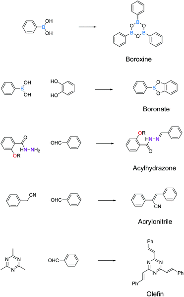
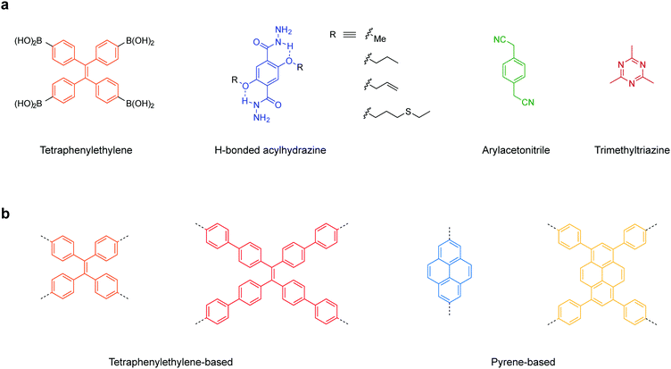
Here, we have summarized the privileged linkages (Fig. 2) and linkers (Fig. 3) suitable for inducing photoluminescence in solid-state 2D COFs. Guided by the 2D COF reticular chemistry, judicious choices of linkages and linkers will give rise to new solid-state photoluminescent 2D COFs.
To turn on the solid-state photoluminescence of 2D COFs, non-radiative pathways caused by π–π stacking or bond rotation must be suppressed.
Boronate and boroxine-type linkages have been used to turn on solid-state PL of 2D COFs (Fig. 4).30,32,34,35,38,39 Through condensation reactions, boron atoms covalently bond to oxygen atoms to form the six-membered ring of boroxine or the five-membered ring of benzodioxaborole, where intramolecular bond rotation can be efficiently restricted. Incorporating AIEgen tetraphenylethylene as the COF backbone functionality, highly emissive 2D COFs have been synthesized with quantum yields up to 32% in the solid state. Luminescent 2D COFs can be used in optoelectronics and ammonia sensing. The high degradability and biocompatibility of boronate or boroxine COFs suggest their applications in biology. Zhang et al. utilized boroxine COFs as smart carriers for in vivo drug delivery as well as bioimaging.40
The second generation of solid-state emissive 2D COFs is based on acylhydrazone linkages (Fig. 5).41,42 Such linkages break the conjugation, cause corrugated layer structures and therefore weaken the π–π stacking in 2D COFs.41 According to recent findings, acylhydrazone linkages together with alkyoxy side chains can induce strong dipole interactions between COF layers, thus giving rise to antiparallel stacked 2D COFs.43 Both intra and interlayer hydrogen bonding are induced in the antiparallel stacked COF layers, providing in-plane rigidity for RIR to turn on PL as well as out-of-plane flexibility for excited-state interlayer proton shift (ESIPS) to induce dual emission. The acylhydrazone 2D COFs provide a platform with high tunability of a wide-ranging color from blue to yellow and even white. This can be ideal for photosensitizers with tunable bandgaps. The ease of encoding functionalities at the side chains also makes such COFs useful as sensors with high sensitivity and selectivity as well as in toxin removal.
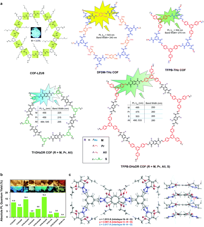 | ||
| Fig. 5 Solid-state fluorescent 2D COFs based on acylhydrazone linkages. (a) Structures of 2D COFs. (b) Absolute PL quantum yields (inset: optical microscopic images under visible light and UV). (c) Antiparallel stacked structure of the Tf-DHzDAll COF with intra and interlayer hydrogen bonding. Readapted with permission from ref. 41, Copyright 2016, American Chemical Society; ref. 42, Copyright 2018, Nature Publishing Group; ref. 43, Copyright 2020, American Chemical Society. | ||
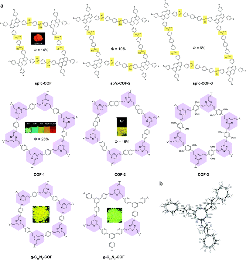
Recently, a new class of C![[double bond, length as m-dash]](https://www.rsc.org/images/entities/char_e001.gif) C based 2D COFs has been discovered to be light emissive in the solid state (Fig. 6).36,44,45 Cyanostilbene species are known as good AIEgens in both small molecule46–48 and polymer49–51 states. Moreover, cyanostilbenes have also been reported to show high emission efficiency in both solution and the solid state.52 When COFs are constructed via acrylonitrile linkages, repeating cyanostilbene units are created in the framework of COFs, giving rise to solid-state fluorescence. Jiang et al. demonstrated a class of light-emitting 2D COFs based on acrylonitrile linkages using pyrene units as the backbone functionality.36,45 This type of COFs exhibited great stability towards strong acid HCl (12 M) and strong base KOH (14 M). Besides, the COFs remained emissive in both the solid state and solution dispersions. Another type of emissive C
C based 2D COFs has been discovered to be light emissive in the solid state (Fig. 6).36,44,45 Cyanostilbene species are known as good AIEgens in both small molecule46–48 and polymer49–51 states. Moreover, cyanostilbenes have also been reported to show high emission efficiency in both solution and the solid state.52 When COFs are constructed via acrylonitrile linkages, repeating cyanostilbene units are created in the framework of COFs, giving rise to solid-state fluorescence. Jiang et al. demonstrated a class of light-emitting 2D COFs based on acrylonitrile linkages using pyrene units as the backbone functionality.36,45 This type of COFs exhibited great stability towards strong acid HCl (12 M) and strong base KOH (14 M). Besides, the COFs remained emissive in both the solid state and solution dispersions. Another type of emissive C![[double bond, length as m-dash]](https://www.rsc.org/images/entities/char_e001.gif) C bonded 2D COFs were synthesized via Aldol condensation between trimethyltriazine and aldehydes.44 The as-synthesized olefin 2D COFs displayed not only fluorescence in the solid state, but also solvatochromic emission when dispersed in various solvents. Although the fluorescence mechanism of the olefin-bonded COFs is not well understood, we propose that the fluorescence is due to the RIR as well as the disruption of π–π stacking via the antiparallel stacking of COF layers. It should be noted that the single-crystal structure of the model compound, tristyryltriazine, shows disorder between clockwise and anti-clockwise styryl arms.44 This strongly implies that these olefin 2D COFs are likely to be antiparallel stacked, which is known to be helpful in inducing fluorescence in acylhydrazone COFs.42,43 The chemical robustness, fluorescence, and porosity of such C
C bonded 2D COFs were synthesized via Aldol condensation between trimethyltriazine and aldehydes.44 The as-synthesized olefin 2D COFs displayed not only fluorescence in the solid state, but also solvatochromic emission when dispersed in various solvents. Although the fluorescence mechanism of the olefin-bonded COFs is not well understood, we propose that the fluorescence is due to the RIR as well as the disruption of π–π stacking via the antiparallel stacking of COF layers. It should be noted that the single-crystal structure of the model compound, tristyryltriazine, shows disorder between clockwise and anti-clockwise styryl arms.44 This strongly implies that these olefin 2D COFs are likely to be antiparallel stacked, which is known to be helpful in inducing fluorescence in acylhydrazone COFs.42,43 The chemical robustness, fluorescence, and porosity of such C![[double bond, length as m-dash]](https://www.rsc.org/images/entities/char_e001.gif) C bonded COFs are highly desirable for practical applications in photocatalysis and sensing.
C bonded COFs are highly desirable for practical applications in photocatalysis and sensing.
As discussed earlier, antiparallel stacking is beneficial for inducing PL in 2D COFs. This is because it can cause misalignment of π moieties between COF layers and hence weaken the π–π interactions. Besides, such a conformation intrinsically forbids free bond rotation.
In a similar vein, increasing the π–π stacking distance in eclipsed stacked solid-state 2D COFs is also helpful for inducing PL via trapping solvent molecules between COF layers. Feng et al. demonstrated a phosphorescent boronate 2D COF at cryogenic temperature (Fig. 8a).55 Motivated by the fact that face-to-face H-aggregation in eclipsed stacked COFs could turn on phosphorescence, they integrated the benzil functionality into the COF backbone, which is a crystallization-induced phosphorescence (CIP) phosphor.56 Interestingly, they found that guest solvent molecules (1,4-dioxane) trapped between the 2D COF layers increase the interlayer distance to 3.7 Å compared to the activated state of 3.4 Å. The 1,4-dioxane-containing BZL-COF showed discernible yellow phosphorescence with the naked eye at 77 K and a lifetime of 1.27 ms, whereas the emission was quenched at 298 K. On the other hand, the activated BZL-COF with an interlayer distance of 3.4 Å was PL-quenched for all temperatures.
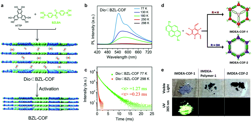 | ||
| Fig. 8 (a) Synthesis of BZL-COF and 1,4-dioxane-containing BZL-COF. (b) Emission spectra of 1,4-dioxane-containing BZL-COF under various temperatures upon excitation at 345 nm. (c) PL lifetime of 1,4-dioxane-containing BZL-COF at 77 K and 298 K. Reproduced with permission from ref. 55. Copyright 2018. Royal Society of Chemistry. (d) Synthesis of staggered stacked IMDEA-COF-1 and eclipsed stacked IMDEA-COF-2. (e) Images of the COFs/polymer under ambient light and 365 nm illumination and emission spectra. Reproduced with permission from ref. 57. Copyright 2018. American Chemical Society. | ||
Construction of 2D COFs with staggered stacking is an effective way to turn on the solid-state emission. In 2018, Zamora et al. reported a solid-state fluorescent imine 2D COF with staggered stacking (Fig. 8d).57 They utilized a pyrene-derived amine to construct an eclipsed stacked and a staggered stacked 2D COF. Normally, the π–π stacking of the pyrene units together with the rotationally labile imine linkages would lead to PL quenching in solid-state 2D COFs. However, the staggered-stacked imine COF exhibits conspicuous green fluorescence upon excitation at 365 nm with an absolute PL quantum yield of 3.5%. In contrast, the amorphous polymer based on the same building blocks and the eclipsed-stacked COF were non-emissive.
Emissive 2D COFs have been successfully applied in sensing,30,31,41,58–60 photocatalysis,61,62 displays,63 photodynamic therapy,64 thermometers65 and diagnostics.64 The enriched pores in 2D COFs can serve as smart carriers for drug delivery.66–68 Emissive COFs can also enable the bioimaging of the drug delivery process.40 For the latter purpose, it may be necessary to convert the COFs to nanoparticles or flakes to allow better dispersion in solution.
2.2 Stimuli responsive 2D COFs
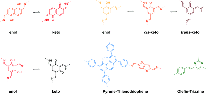
Stimuli-responsive 2D COFs are engineered in such a way that changes in intermolecular or intramolecular interactions, or molecular reorganization occur in response to external stimulation by light, moisture, pH or heat, leading to changes in the emission wavelength or intensity. In the following section, we will review representative examples of stimuli responsive 2D COFs based on solvatochromism and photoisomerization, and further discuss how these properties are induced based on structural design.A major category of solvatochromic 2D COFs is based on salicylidene-analogue functionalities, which can undergo enol–keto tautomerization triggered by a protic solvent when integrated into 2D COFs (Fig. 10).63,69–72 Traditionally, chromism in salicylideneaniline-based small molecules has to be triggered by high energy input such as light irradiation or heat, leading to a reversible tautomeric process between enol, cis-keto and trans-keto forms.73–75 Interestingly, no heat or light is needed for triggering chromism in this class of COFs because the presence or absence of moisture alone can induce the reversible tautomerization. The well-ordered π-stacked arrays and 1-D channels in 2D COFs allow protons to activate collective molecular reorganization. The solvatochromism is caused by enhanced charge transfer between the electron donor and acceptor dyads. Using a salicylideneaniline COF as an example, the salicylideneaniline units become stronger electron acceptors via enol–keto tautomerization, therefore facilitating the charge transfer process and the narrowing of the band gap.71
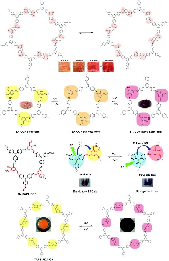 | ||
| Fig. 10 Solvatochromic 2D COFs based on enol–keto tautomerization. The insets show the appearance of the COFs under different conditions. | ||
Beside salicylidene-type functionalities, Bein and Auras synthesized a solvatochromic imine 2D COF based on electron donor–acceptor dyads between pyrene and thienothiophene building units (Fig. 12).76 Their time-dependent density functional theory (TD-DFT) calculation suggested that one-electron charge transfer from pyrene to thienothiophene units occurs in the excited state, while surrounding protic solvents can redshift the light absorption. Furthermore, the authors prepared oriented films of the Py-TT COF with a thickness of 360 nm, which is highly responsive to humidity. The dried film exhibited a fast response to H2O-saturated gas streams (0.21 s), while the wetted film showed an even faster response to dry gas streams (0.15 s).
Recently, Perepichka and coworkers reported a type of arylene vinylene 2D COFs with triazine functionalities showing solid-state fluorescence.44 Interestingly, the COF exhibited solvatochromic fluorescence when dispersed in various solvents, although tautomerization was not involved; instead the mechanism may involve charge transfer between the COF and the solvent.
Solvatochromism in 2D COFs is highly sensitive and even moisture can trigger a conspicuous color change. Thus, humidity sensors have been built using solvatochromic COFs.69,72,76 In addition, the presence of basic enamine groups in the 1D channel of salicylidene-type COFs provides the basis for chemoselective separation.70 Enol–keto tautomerization in 2D COFs as a result of external stimuli has been exploited to reversibly engineer the bandgaps in COFs since the electronic structure is affected by molecular reorganisation. In one case, the bandgap narrowing allows better optical limiting performance.71 Besides sensing, the solvatochromic fluorescence in 2D COFs also provides a means to tune light emission, producing even a white color (Fig. 11).63
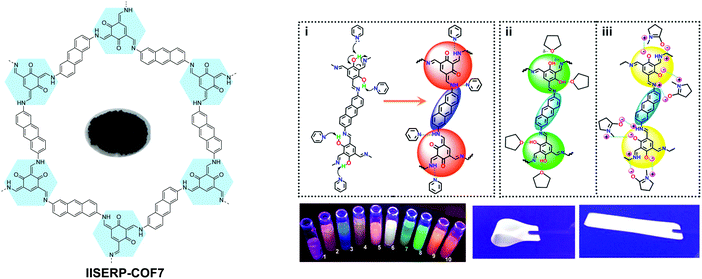 | ||
| Fig. 11 Solvatochromic emissive 2D COF based on enol–keto tautomerization. The proposed mechanism is shown for solvatochromic emission of the COF. COF dispersions in different solvents placed under a UV lamp. (1, THF; 2, 1,4-dioxane; 3, glyoxal; 4, pyridine; 5, DMA; 6, NMP; 7, ethanol; 8, formamide; 9, picoline; 10, DMF.) The COF in a flexible solid PMMA polymer matrix producing white emission. Reproduced with permission from ref. 63. Copyright 2017. American Chemical Society. | ||
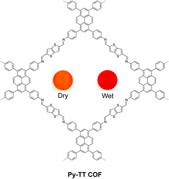 | ||
| Fig. 12 Solvatochromic 2D COF based on pyrene–thienothiophene electron donor–acceptor dyads. Readapted with permission from ref. 76. Copyright 2018. Nature Publishing Group. | ||
One interesting observation is that all solvatochromic COFs reported to date are 2D COFs. It can be inferred that the periodic π-stacked arrays in 2D COFs are vital to induce solvatochromism. This also suggests that solvatochromism can be used as a property to differentiate 2D COFs from 3D ones.
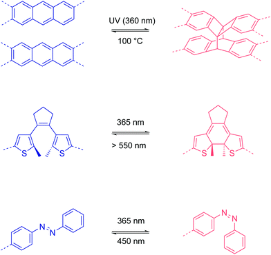
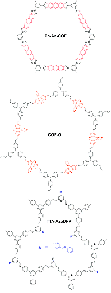
In 2015, Jiang et al. demonstrated a photo-responsive 2D boronate COF that was constructed from anthracene backbone functionalities.77 Due to the eclipsed stacking in the 2D COF, the anthracene moieties are arranged face-to-face and undergo photo-induced dimerization via interlayer [4π+4π] cycloaddition. Heating to 100 °C reverses the dimerization reaction. By repeating UV irradiation and heating, the light absorption of the COF can be reversibly tuned.
In 2019, Zhang et al. integrated photo-responsive 1,2-bis(2-methylthien-3-yl)cyclopentene (DAE) into a 2D imine COF.78 The DAE units can undergo reversible Cope rearrangement between an open state and a closed state upon light irradiation at 365 nm and >550 nm, respectively. When the COF was prepared in the form of a film (0.6 μm), the conductivity increased from (1 ± 0.25) × 10−7 S cm−1 in the open state to (2 ± 0.23) × 10−5 S cm−1 in the closed state, which is a ∼200-fold increase, after irradiation for 6 min at room temperature.
Azobenzene is famous for its trans–cis photoisomerization.79 However, when the azobenzene units are integrated into the backbone of COFs, the close-packed rigid framework structures inhibit this trans–cis isomerization due to the high energy barriers. Recently, Trabolsi and coworkers reported a 2D imine COF as a light-operated reservoir.80 Interestingly, they introduced the azobenzene units as dangling groups in the COF pore structure. When the azobenzene units are in the trans state, the dangling groups occupy the COF channels as the pore walls, mimicking a honeycomb network but with periodic disconnection/defects (Fig. 14). The free volume of the COF pores and the disconnection at one side of the azobenzene moieties allow the photoisomerization process. They found that the light absorption and emission behavior of the COF dispersion in ethanol, as well as its hydrophilicity, can be reversibly tuned via photo-induced trans–cis isomerization. Furthermore, the trans–cis isomerization enables a reversible change of pore sizes of 1.2 nm for the trans state and 2.7 nm for the cis state. Based on the photoswitching of hydrophilicity and pore size, their COF realized the light-induce capture and release of rhodamine B, which is promising for drug delivery applications.
2.3 CO2 storage and conversion
The rising level of carbon dioxide (CO2) in the environment is a major concern. A key step in reducing carbon footprints is the storage and fixation of CO2 into fuels. Materials scientists have created a wide range of porous materials, some of which show potential as CO2 capture and storage materials.81,82 COFs are potential CO2 sorbents in view of their porosity, thermal stability and tunable functionality.8,83–87 Various catalysts can also be immobilized in the channels in COFs to convert CO2 to useful chemicals. The different sorption capacities in COFs are attributed to the interplay of various complex factors such as surface area, pore geometry and chemical functionality. In this section, we will discuss the strategies to improve the gas sorption capacity of 2D COFs for CO2 capture and conversion.The primary factor for the CO2 intake capacity is the surface area of COFs. Despite the large surface area of 3D COFs, most structures are interpenetrated, blocking the pores needed for CO2 capture. In contrast, eclipsed-stacked 2D COFs have unblocked channels for gas storage. Although the ideal surface areas of COFs for various sorbents can be estimated via simulation, the experimental values are often lower than the theoretical ones due to defects, polycrystallinity, and insufficient activation. Routine activation procedures have been established, including supercritical CO2 extraction, Soxhlet extraction, vacuum at temperature, etc. Here, we will review the strategies to improve the experimental surface areas of COFs.
In 2017, Banerjee et al. demonstrated an organic terracotta method to construct ultraporous 2D COFs (Fig. 15).88 Using a solid-state reaction at 170 °C and p-toluenesulfonic acid (PTSA) as the catalyst, they obtained 2D COFs with Brunauer–Emmett–Teller (BET) surface areas as high as 3109 m2 g−1, which are 2 to 3-fold higher than those synthesized via solvothermal conditions. The large surface area was attributed to the larger particle dimensions, ordered pore channels, and long-range periodicity of the COF. The suitable choice of acid catalyst creates PTSA-amine salts with H-bonded lamellar structures, which act as templates for 2D COF growth. Their study also revealed that high temperature was beneficial for COFs to grow into larger particles, and a solvent-free (or less) condition could prevent the COF pores from being blocked by the solvent molecules.
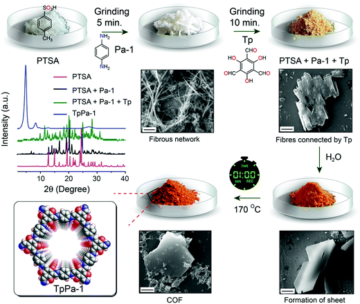 | ||
| Fig. 15 Synthesis of ultraporous 2D COFs via an organic terracotta process. Reproduced with permission from ref. 88. Copyright 2017. American Chemical Society. | ||
In 2018, we reported a strategy to enhance the surface area via construction of a lacunary 2D COF with frustrated bonding (Fig. 16).89 Using π-rigid and rotationally flexible tetraphenylethylene as the backbone, two distinct 2D COFs can be divergently synthesized under different combinations of solvents. One of the COFs (TPE-COF-I) was fully bonded via a [4+4] pathway, while the other (TPE-COF-II) had frustrated bonding with dangling aldehyde groups via a [4+2] pathway. The lacunary structure of the frustrated bonding TPE-COF-II gives rise to an enhanced pore volume of 2.14 cm3 g−1 (P/P0 = 0.984) compared to 1.65 cm3 g−1 (P/P0 = 0.984) for the fully bonded TPE-COF-I. Due to the large BET surface area (2168 m2 g−1) of the frustrated COF, it exhibits a great CO2 uptake capacity of 118.8 cm3 g−1 (23.2 wt%, 1 atm, 273 K). The CO2 intake per unit surface area at 273 K was calculated to be 54.8 mm3 m−2 for TPE-COF-II and 39.4 mm3 m−2 for TPE-COF-I, suggesting that the presence of dangling formyl groups at pore walls is helpful in binding CO2 molecules.
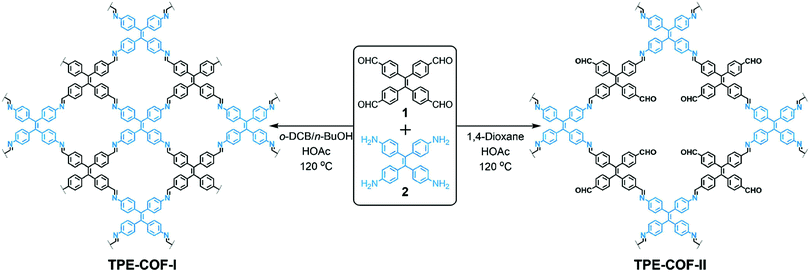 | ||
| Fig. 16 Divergent construction of a frustrated bonding 2D COF. Reproduced with permission from ref. 89. Copyright 2018. American Chemical Society. | ||
Other than the surface area, the functional groups in COFs also play an important role in sorption. Useful CO2-philic functionalities have been summarized in Fig. 17. The interaction mechanism involves either acid–base or dipole interactions between CO2 molecules and the built-in functionality. However, COFs with high affinity to CO2 do not necessarily show high CO2 intake, limited by their surface areas. Therefore, balanced methods need to be developed to introduce CO2-philic groups without sacrificing the surface area in COFs.
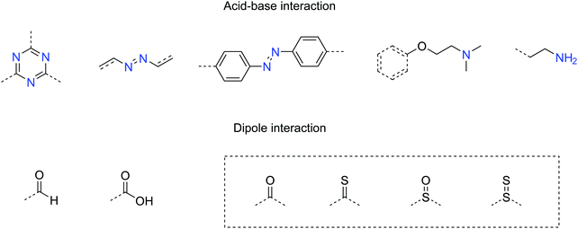 | ||
| Fig. 17 Useful functional groups showing high affinity with CO2 (dash box: these functionalities have been predicted to have strong affinity with CO2 but have not yet been tested in COFs). | ||
A more efficient way of utilizing these materials is to incorporate catalytic capability so that the sequestered CO2 can be converted into value-added carbon products. Although simultaneous CO2 fixation and conversion is still a big challenge using COFs, they have been explored in photocatalytic or electrocatalytic systems for CO2 conversion. Herein, we will review a few representative examples of CO2 conversion using 2D COFs.
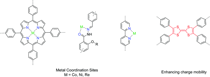
2D COFs provide a well-defined platform with tunable bandgaps and open sites for coordinating to metals. In addition, their structural tunability and porosity with high surface area make COFs promising catalyst candidates for both photocatalytic and electrocatalytic systems. A pool of useful building units for CO2 conversion is given in Fig. 18. Yaghi et al. demonstrated a 2D COF impregnated with a cobalt porphyrin catalyst for the electrochemical conversion of CO2 into CO in water.90 Using an overpotenial of −0.55 V, a high faradaic efficiency of 90% with a turnover number up to 290![[thin space (1/6-em)]](https://www.rsc.org/images/entities/char_2009.gif) 000 under neutral conditions was achieved. To address the issue of low charge mobility in COFs, Lan et al. introduced tetrathiafulvalene units into the porphyrin COF system and exfoliated the COF into nanosheets, achieving a maximum faradaic efficiency of 99.7% with an overpotential of −0.8 V.91 The electrical conductivity of COFs is a bottleneck in many applications requiring shuttling of electrons, and hopefully that can be improved by developing new conjugated covalent linkages and building units.92 Alternatively, COFs with channels with immobilized nanocatalysts can be utilized as diffusion layers for both CO2 and ions, achieving both gas fixation and conversion into energy storage intermediates.93
000 under neutral conditions was achieved. To address the issue of low charge mobility in COFs, Lan et al. introduced tetrathiafulvalene units into the porphyrin COF system and exfoliated the COF into nanosheets, achieving a maximum faradaic efficiency of 99.7% with an overpotential of −0.8 V.91 The electrical conductivity of COFs is a bottleneck in many applications requiring shuttling of electrons, and hopefully that can be improved by developing new conjugated covalent linkages and building units.92 Alternatively, COFs with channels with immobilized nanocatalysts can be utilized as diffusion layers for both CO2 and ions, achieving both gas fixation and conversion into energy storage intermediates.93
Photocatalytic systems using 2D COFs have also been developed for CO2 conversion.94–97 A good design has the backbone functionalities serving as the coordination sites for the metal catalyst, while the organic COF skeleton plays the role of photosensitizers. The current benchmark performance of COF photocatalysts for CO2 conversion to CO is 1400 μmol g−1 h−1 with the addition of a dye as a photosensitizer.96 In fact, a myriad of different combinations between COFs and metal catalysts can be screened to identify the optimal system.
2.4 Ion conduction
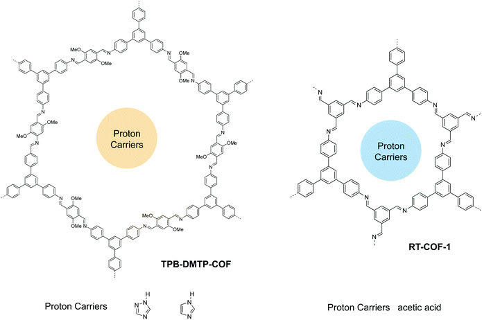
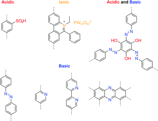
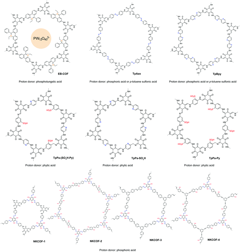
COFs possess aligned 1D channels that can be modified chemically to enable ion conduction in a pre-defined manner. The porous structures of COFs endow them with abundant free space for ion diffusion, yet their framework rigidity ensures that these pores do not collapse over a wide temperature range;98,99 thus they have good potential as solid-state ion conductors. Their rigidity and phase stability contrast with the temperature-driven phase transition in conventional polymer electrolytes. The glassy state is necessary in some polymer electrolytes to create free volume for ion transport, whereas well-designed COFs can be considered as true solid-state electrolytes because they have no glass transition state.100In recent years, proton conducting materials have spurred tremendous interest among researchers due to their application in fuel cells, sensors, and electronic devices.101–103 Reported proton conductive 2D COFs are summarized in Table 3. The covalent coupling of proton donating groups in the COF skeleton can promote proton conductivity and single-ion conduction. However, the intrinsic conductivity of COFs is usually low because the number of acidic groups that can be anchored in a unit cell is limited. One way to boost the proton conductivity is to dope external proton donors inside the channels of COFs. Overall, there are two strategies for the synthesis of proton conductive COFs. One is doping external proton carriers inside the pores of COFs, utilizing solely the channels for proton conduction (Fig. 19); the other is encoding functionalities such as ionic, acidic, and basic groups onto the COF pore walls to facilitate proton conduction from external donors (Fig. 21).
| COF | Proton conductivity (S cm−1) | RH (%) | T (°C) | E a (eV) | Fuel cell performance Pmax (mW cm−2) | Ref. |
|---|---|---|---|---|---|---|
| PA@Tp-Azo | 9.9 × 10⁻⁴ | 98 | 59 | 0.11 | — | 106 |
| PA@Tp-Stb | 2.3 × 10⁻⁵ | 98 | 59 | 0.14 | — | |
| phytic@TpPa-Py | 3.00 × 10⁻⁴ | 0 | 120 | 0.10 | — | 107 |
| phytic@TpPa-SO3H | 7.5 × 10⁻⁵ | 0 | 120 | — | — | |
| Phytic@TpPa-(SO3H-Py) | 5.00 × 10⁻⁴ | 0 | 120 | 0.16 | — | |
| Trz@TPB-DMTP-COF | 1.10 × 10⁻³ | — | 130 | 0.21 | — | 104 |
| Im@TPB-DMTP-COF | 4.37 × 10⁻³ | — | 130 | 0.38 | — | |
| EB-COF:PW12O403− | 2.82 × 10⁻⁶ | 97 | 25 | 0.24 | — | 110 |
| EB-COF:Br | 3.32 × 10⁻³ | 97 | 25 | — | — | |
| NUS-9 | 1.24 × 10⁻² | 98 | 25 | — | — | 111 |
| NUS-10 | 3.96 × 10⁻² | 98 | 25 | — | — | |
| PA@BpTpy-MC | 2.50 × 10⁻³ | 0 | 120 | 0.11 | 7.5 (at 50 °C, 0% RH) | 112 |
| PA@BpTpy-ST | 1.98 × 10⁻³ | 0 | 120 | 0.12 | — | |
| RT-COF-1 | 1.83 × 10⁻⁵ | 100 | 40 | — | — | 105 |
| RTCOF-1Ac | 5.25 × 10⁻⁴ | 100 | 40 | — | 7.64 (at 60 °C, 100% RH) | |
| RT-COF-1AcB | 1.07 × 10⁻⁴ | 100 | 40 | — | 12.95 (at 60 °C, 100% RH) | |
| LiCl@RT-COF-1 | 6.45 × 10⁻³ | 100 | 40 | — | 4.06 (at 60 °C, 100% RH) | |
| PTSA@TpAzo | 7.80 × 10⁻² | 95 | 80 | 0.11 | 24 (at 60 °C, 100% RH) | 108 |
| PTSA@TpBpy | 6.20 × 10⁻² | 95 | 80 | 0.11 | — | |
| PTSA@TpBD(Me)2 | 5.30 × 10⁻² | 95 | 80 | 0.23 | — | |
| Aza-COF-1H | 1.23 × 10⁻³ | 97 | 50 | 0.29 | — | 113 |
| Aza-COF-2H | 4.80 × 10⁻³ | 97 | 50 | 0.45 | — | |
| BIP(COF) | 3.20 × 10⁻² | 95 | 95 | 0.31 | — | 114 |
| H3PO4@NKCOF-1 | 1.13 × 10⁻¹ | 98 | 80 | 0.14 | 81 (at 60 °C, 100% RH) | 109 |
| H3PO4@NKCOF-2 | 4.28 × 10⁻² | 98 | 80 | 0.24 | 45 (at 60 °C, 100% RH) | |
| H3PO4@NKCOF-3 | 1.12 × 10⁻² | 98 | 80 | 0.40 | 24 (at 60 °C, 100% RH) | |
| H3PO4@NKCOF-4 | 7.71 × 10⁻² | 98 | 80 | 0.08 | 56 (at 60 °C, 100% RH) |
To use COFs as proton transport membranes, processability and stability are important considerations besides conductivity. Jiang et al. reported a highly crystalline and robust COF with large pore volume for proton conduction.104 Due to the high BET surface area, they doped triazole or imidazole as proton carries into the COF channels with a high loading of 180 wt% and 155 wt%, achieving proton conductivities of 1.1 and 3.78 mS cm−1 at 403 K, respectively. Using a one-pot synthesis, Zamora et al. trapped acetic acid into the COF with 3.5 molecules per formula unit, achieving a proton conductivity of 0.525 mS cm−1 at 313 K (100% relative humidity). They further processed the COF into thin films for use in fuel cells, achieving a power density of 12.95 mW cm−2 and a maximum current density of 53.1 mA cm−2.105
Immobilizing basic groups in the 1-D channels of a COF can facilitate proton dissociation from external carriers, thereby enhancing the proton conductivity. Besides, acidic groups can improve the intrinsic proton conductivity of COFs. The beneficial functional groups for enhancing proton conduction are summarized in Fig. 20. Banerjee and coworkers reported the first proton conductive COF, which bears basic azobenzene functional groups for loading phosphoric acid.106 Compared to an isoreticular COF without azo groups, the azo-COF achieved a proton conductivity of 0.99 mS cm−1 at 332 K under 98% relative humidity. In following work, the authors further demonstrated a multi-component hybrid COF with both acidic sulfonyl and basic pyridinic functionalities in the hybrid COF skeleton.107 Using phytic acid as the proton donor, they achieved anhydrous proton conductivity up to 0.5 mS cm−1 at 393 °C. In 2018, they reported a method to prepare self-standing flexible COF membranes with superprotonic conductivities.108 Loaded with p-toluene sulfonic acid as proton carriers, the COF membrane with azo functional groups achieved a proton conductivity of 63 mS cm−1 at 303 K under 95% relative humidity. The proton exchange membrane fuel cell based on the COF membrane achieved a power density of 24 mW cm−2. In line with the strategy of constructing COFs with both acid and base groups, Zhang et al. designed a new COF building unit with both acidic phenol and basic azo functionalities.109 The neat COFs achieved an intrinsic proton conductivity up to 7.08 mS cm−1 at 353 K under 98% relative humidity. When loaded with phosphoric acid (≤8.1 wt%) as the external proton donor, the proton conductivity increased to 113 mS cm−1 at 353 K under 98% relative humidity.
Ma et al. demonstrated a proton conductive 2D COF with cationic backbone functionality.110 The anions in the COF channels can be exchanged with PW12O403−, achieving a proton conductivity of 3.32 mS cm−1 at room temperature under 97% relative humidity. The authors postulated that the hydrophilic polyoxometalate anions in the COF channels formed water clusters, providing interconnected hydrogen bonding networks to boost the proton conductivity. In their experiments, they used H3PW12O40 for anion exchange with the COF, which may result in partial ion exchange and trapping of HPW12O402− and H2PW12O40−. Proton donors enhance the proton conductivity and a superacid with a high pKa value is beneficial (Fig. 21).
Increasingly, COF research will focus on multifunctional applications and these necessitate the integration of various components to work synergistically. The tailorable 1-D channels in 2D COFs are useful for gas storage and ion conduction. Combination of these properties engenders new applications of COFs such as metal-ion–gas batteries, which require a stable cathode with high surface area to capture gas molecules as well as the ability to facilitate the diffusion of redox species. As a proof of concept, we reported COF-based Li–CO2 batteries with enhanced energy capacity and rate performance (Fig. 22).93 An acylhydrazone COF was used as the cathode in the Li–CO2 battery to provide diffusion channels for both CO2 gas and Li ions. In addition, coordinated Ru nanoparticles are well-positioned to catalyse CO2 conversion via rimming the pores of the acylhydrazone COF. Such synergetic design greatly facilitates the kinetics of charge/discharge cycles in the batteries, leading to enhanced battery rate performance and cycle life. The COF-based Li–CO2 battery achieved a high energy capacity of 27![[thin space (1/6-em)]](https://www.rsc.org/images/entities/char_2009.gif) 348 mA h g−1 (7.38 mA h cm−2) at a current density of 200 mA g−1 and can endure a maximum current density of 4 A g−1 without decay of the discharge/charge voltage. The battery ran for 200 cycles at a current density of 1 A g−1 within a limiting capacity of 1000 mA h g−1.
348 mA h g−1 (7.38 mA h cm−2) at a current density of 200 mA g−1 and can endure a maximum current density of 4 A g−1 without decay of the discharge/charge voltage. The battery ran for 200 cycles at a current density of 1 A g−1 within a limiting capacity of 1000 mA h g−1.
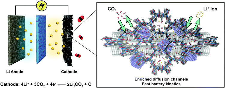 | ||
| Fig. 22 Li–CO2 battery based on the COF-incorporated cathode. Adapted with permission from ref. 93. Copyright 2019. Wiley-VCH. | ||
3. COFenes
Reducing the thickness of 3D solids into 2D sheets generates novel properties due to quantum confinement effects and dimensionality-dependent electronic and optical properties, and this has spurred a huge research field on 2D materials.115,116 Considering their layered structure, 2D COFs provide opportunities to access a new class of organic 2D materials that are highly tunable in structure and properties. Similar to graphene, single or few layer COF flakes have to be exfoliated from bulk 2D COFs. COFenes are defined as monolayer crystals generated by decoupling the non-covalent interactions in bulk 2D COF layers. To distinguish COFenes from amorphous 2D polymers such as covalent organic nanosheets (CONs),124 COFenes should possess the following features: (1) the covalent linkages propagate in a 2D plane; (2) the material exhibits a crystalline network structure inherited from the parent COF; and (3) a thickness less than a few unit cells. In this review, we will categorize qualified examples as COFenes, some of which were addressed as CONs or COF nanosheets in the past but fulfil the above requirements.3.1 Advantages of functional COFenes
Do COFenes offer new properties different from those of their bulk counterparts? Research on bulk 2D COFs has shown that excitons can move both across the covalent linkages in the xy plane and the π columns along the z axis.45,117,118 By reducing bulk 2D COFs into COFenes, the movement of excitons is confined in a 2D plane, giving rise to organic quantum wells with new electronic properties and band structures.119 The absence of interlayer interactions in COFenes may allow fluorescence to be turned on, whereas this would be quenched by π–π interactions in the bulk.31,120 In addition, open-shell radical structures incorporated in the scaffold of COFenes are free from interlayer interactions, thereby stabilizing the ferromagnetic ground state in these systems. Wu et al. reported a 2D covalent organic radical framework via interfacial synthesis (Fig. 23).121 Polychlorotriphenylmethyl radical moieties were connected via diacetylene linkages in the ordered framework, giving rise to a moderate anti-ferromagnetic exchange interaction of J = −375 cm−1. The authors reported these results on bulk-like films as thick as 95 nm. There is a possibility that if a COFene is generated from such materials, the ferromagnetic properties can be enhanced.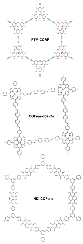 | ||
| Fig. 23 Representative COF thin film (95 nm) or COFenes reported in ref. 121–123, showing interesting properties in contrast to the bulk. | ||
Another benefit of having a COFene is that the exposed surface functional groups on either of its faces should provide readily available catalytic sites for heterogenous catalysis. In 2019, Jiang and coworkers demonstrated the use of COFenes for photocatalytic CO2 reduction (Fig. 23).122 Using co-coordinated porphyrin as the backbone functionality, the COF-367-Co COFene exhibited a CO2 production rate of 10![[thin space (1/6-em)]](https://www.rsc.org/images/entities/char_2009.gif) 162 μmol g−1 and a selectivity of ca. 78%, which was much higher than the bulk counterpart's CO production rate of 124 μmol g−1 and selectivity of 13%. They found that Co atoms are vital for adsorbing CO2 molecules. Although the bulk COF possesses a larger BET surface area, the Co atoms are buried deep within the framework, resulting in a lower adsorption capacity of CO2. This suggests that the catalytic activity of the COFene is largely enhanced on account of the exposed backbone functionalities. Very recently, Segura et al. reported a naphthalene diimide-based COFene for the electrocatalytic oxygen reduction reaction (ORR) (Fig. 23).123 In electrocatalysis, a well-dispersed thin catalyst layer can enhance the contact between the electrode and the catalytic sites. A 6–7 nm thick NDI-COFene was coated onto the glassy carbon (GC) electrode. Linear sweep voltammetry revealed good ORR reactivity of the COFene catalyst with an onset potential of (−0.25 V vs. SCE) and a limiting current of ∼3.8 mA cm−2. It is noteoworthy that the amorphous NDI polymer exhibited almost no ORR reactivity because of the lack of well-defined pores for O2 diffusion; this clearly evidenced that the crystallinity of COFenes distinguishes themselves from amorphous materials. Furthermore, we believe that COFenes may serve as a new class of carbocatalysts like graphene oxide,124 with the possibility of attaining higher selectivity.
162 μmol g−1 and a selectivity of ca. 78%, which was much higher than the bulk counterpart's CO production rate of 124 μmol g−1 and selectivity of 13%. They found that Co atoms are vital for adsorbing CO2 molecules. Although the bulk COF possesses a larger BET surface area, the Co atoms are buried deep within the framework, resulting in a lower adsorption capacity of CO2. This suggests that the catalytic activity of the COFene is largely enhanced on account of the exposed backbone functionalities. Very recently, Segura et al. reported a naphthalene diimide-based COFene for the electrocatalytic oxygen reduction reaction (ORR) (Fig. 23).123 In electrocatalysis, a well-dispersed thin catalyst layer can enhance the contact between the electrode and the catalytic sites. A 6–7 nm thick NDI-COFene was coated onto the glassy carbon (GC) electrode. Linear sweep voltammetry revealed good ORR reactivity of the COFene catalyst with an onset potential of (−0.25 V vs. SCE) and a limiting current of ∼3.8 mA cm−2. It is noteoworthy that the amorphous NDI polymer exhibited almost no ORR reactivity because of the lack of well-defined pores for O2 diffusion; this clearly evidenced that the crystallinity of COFenes distinguishes themselves from amorphous materials. Furthermore, we believe that COFenes may serve as a new class of carbocatalysts like graphene oxide,124 with the possibility of attaining higher selectivity.
The presence of ionic groups or polarized species on COFenes means they have better solution-processability than 2D COFs and are amenable to the membrane fabrication needed for filtration applications. The pore sizes of 2D COFs are usually in the range of nanometers, which are too large for selective filtration of metal ions or gas molecules.125 Through a delamination and restacking process, the channels in COFenes become partially overlapped, achieving a pore narrowing effect. Compared to membranes based on conventional 2D materials such as graphene,126 COFene membranes with well-defined pores can provide much higher permeance as well as better selectivity.
3.2 Functionality-directed synthesis of COFenes
We will review the two major methods to obtain COFenes: top-down exfoliation from bulk 2D COFs and bottom-up direct synthesis of COFenes via interface confinement (Fig. 24). Each method possesses its own advantages and drawbacks. For the top-down method, scalable CONs can be obtained via mechanical or chemical exfoliation from a big pool of 2D COFs; however, exfoliation via brutal forces or harsh chemical conditions is destructive to the crystallinity and less controlled, resulting in uncontrollable thickness and ill-defined morphologies such as nanoparticles instead of thin sheets. In the bottom-up method, COFenes can be obtained with better crystallinity and better-controlled thickness; however, this method is difficult to scale up and the choice of building units is rather limited.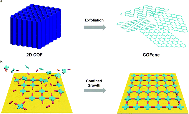 | ||
| Fig. 24 Preparation methods of COFenes. (a) Top-down exfoliation from bulk 2D COFs. (b) Bottom-up interface confined synthesis of COFenes. | ||
In this section, we will summarize the privileged functionalities used in the preparation of COFenes, as well as elaborate on the new properties afforded by these materials.
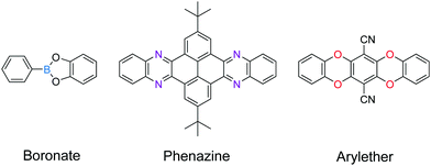
![[double bond, length as m-dash]](https://www.rsc.org/images/entities/char_e001.gif) C linkages, boronate linkages form a five-membered ring with two B–O bonds; the more rigid nature of these bonds restricts the bond rotation and planarizes the 2D porous organic sheets during the delamination process. Therefore, linkages with multiple connection bonds can enhance the in-plane robustness of 2D COFs, facilitating the production of COFenes via the top-down exfoliation method. For instance, TEM studies revealed that thin sheets of phenazine-linked 2D COFs showed good in-plane crystallinity.130,131 In a similar vein, the delamination of arylether-based 2D COFs132,133 should be explored (Fig. 26).
C linkages, boronate linkages form a five-membered ring with two B–O bonds; the more rigid nature of these bonds restricts the bond rotation and planarizes the 2D porous organic sheets during the delamination process. Therefore, linkages with multiple connection bonds can enhance the in-plane robustness of 2D COFs, facilitating the production of COFenes via the top-down exfoliation method. For instance, TEM studies revealed that thin sheets of phenazine-linked 2D COFs showed good in-plane crystallinity.130,131 In a similar vein, the delamination of arylether-based 2D COFs132,133 should be explored (Fig. 26).
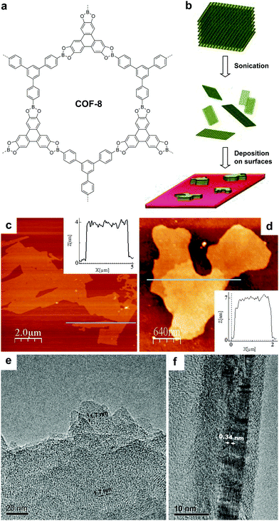 | ||
| Fig. 25 (a) Structure of COF-8. (b) Scheme of delamination of COF-8 and deposition on surfaces. AFM topographic images of COFene-8 on (c) mica and (d) silica substrates. TEM images showing the (e) in-plane and (f) out-of-plane crystallinity of COFene-8. Reproduced with permission from ref. 17. Copyright 2011. Wiley-VCH. | ||
Other than specific COF linkages which can reinforce in-plane robustness, the structure of the molecular scaffolds also facilitates the exfoliation of 2D COFs. In 2013, Dichtel et al. reported a 2D acylhydrazone COF which can be exfoliated into a COFene via ultrasonication in solvents such as 1,4-dioxane and water (Fig. 27).134 COF-43 was sonicated in tetrahydrofuran (THF) to afford nanoparticles that were hundreds of nanometers thick. On the other hand, sonication of COF-43 in 1,4-dioxane produced COFene-43 with a thickness of 1.32 ± 0.37 nm, corresponding to 3–5 layers. Interestingly, selected area electron diffraction (SAED) of COFene-43 displayed a hexagonal diffraction pattern, indicating in-plane long-range order. We infer that the strong in-plane robustness of COF-43 comes from the intralayer hydrogen bonding as mentioned in the section of light emissive 2D COFs. The NH⋯O hydrogen bonding within the six-membered ring can restrict intramolecular bond rotation, giving rise to a highly stable in-plane structure during the exfoliation process.
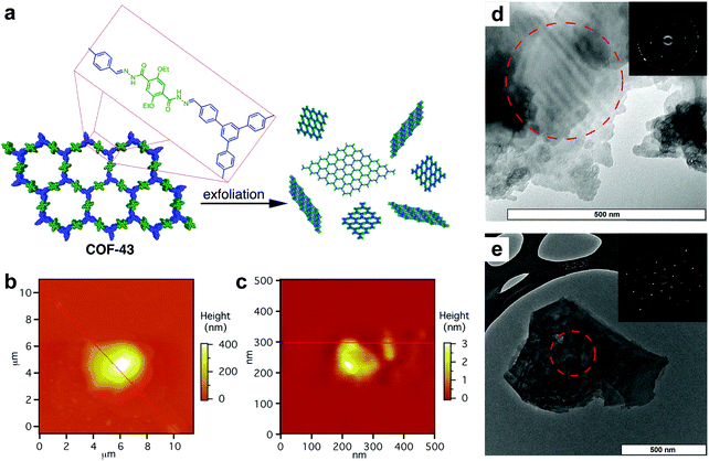 | ||
| Fig. 27 (a) Scheme of preparation of COFene-43. AFM images of COF-43 deposited onto freshly cleaved mica from (b) THF, which indicates particle sizes corresponding to hundreds of layers, and from (c) 1,4-dioxane, which shows platelets corresponding to few-layer structures. TEM images of a COF-43 suspension in (d) THF and (e) 1,4-dioxane (insets: SAED). Reproduced with permission from ref. 134. Copyright 2013. American Chemical Society. | ||
Bein's group demonstrated that tetraphenylethylene33 and pyrene37 units are beneficial for growing highly crystalline 2D COFs. Judging from their TEM images, such COFs are expected to survive strong mechanical disturbance and produce crystalline exfoliated COFenes. In Bein's work on highly crystalline TPE COFs, they also showed that propeller-shaped triphenylamine (TPA) units are beneficial for enhancing the crystallinity of 2D COFs.33 In 2017, Han, Zhang and coworkers reported the exfoliation of a TPA-based imine 2D COF into COFene (Fig. 28).19 The authors claimed that the judicious choice of two flexible TPA building units (amine and aldehyde) weakened the interlayer stacking, leading to easy exfoliation into 2D nanosheets. A colloidal solution exhibiting the Tyndall effect could be obtained by sonication of the TPA-COF in ethanol. Low-dose TEM allowed the visualization of the highly ordered porous structure of the TPA-COFene. AFM measurements revealed that the exfoliated nanosheets had a thickness of 3.5 ± 0.3 nm, corresponding to 9 ± 1 layers. The exfoliated TPA-COFene was adopted as a platform for DNA detection. The TPA-COFene acted as a fluorescence quencher for a dye-labelled DNA probe. Upon the hybridization of the probe with the target DNA, the fluorescence tag was removed from the COFene, leading to the recovery of fluorescence; the quantitative detection of target DNA using this method had a detection limit as low as 20 pM.
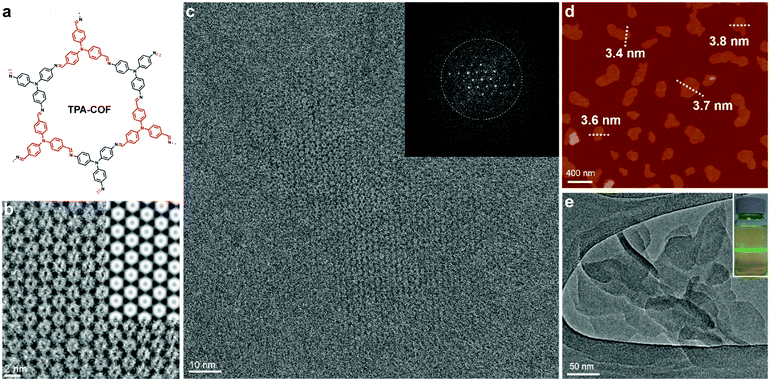 | ||
| Fig. 28 (a) TPA-COF reported by Zhang et al. (b) Enlarged high-resolution TEM of TPA-COFene denoised by using a Wiener filter. Inset: Simulated HRTEM image. (c) Low-dose high-resolution motion-corrected TEM image of TPA-COFene. Inset: Fast Fourier transform (FFT) of the TEM image. (d) AFM image of TPA-COFene. (e) TEM images of TPA-COFene. Inset: Photograph of the Tyndall effect of the TPA-COFene suspension. Reproduced with permission from ref. 19. Copyright 2017. American Chemical Society. | ||
In 2016, Zang and coworkers reported a cationic imine 2D COF based on ethidium bromide building units.110 The charge repulsion between the COF backbone functionalities is expected to facilitate the exfoliation process. In 2018, Ajayaghosh and coworkers demonstrated the exfoliation of this 2D COF (Fig. 29).135 According to their report, EB-TFP could be self-exfoliated at room temperature when suspended in water for 2 days without any physical or chemical disturbance. The exfoliated COFene showed an AFM thickness of 1.5 ± 0.3 nm, and good crystallinity under HRTEM. The cationic COFene exhibited fluorescence at 510 nm. A new emission band at 600 nm was observed when negatively charged calf thymus DNA (ctDNA) binds to the COFene to form a COFene–DNA reassembly. They further found that the perfectly matched double-strand DNA showed a higher PL enhancement compared to single-strand DNA of double-strand DNA with mismatched sequences, inidcating that the COFene could function as a sensor for double-strand DNA.
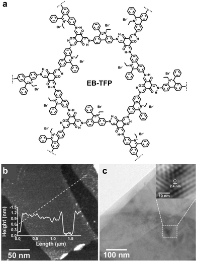 | ||
| Fig. 29 (a) Structure of the EB-TFP COF. (b) AFM image of the EB-TFP COFene. (c) HRTEM of the EB-TFP COFene. Reproduced with permission from ref. 135. Copyright 2018. Wiley-VCH. | ||
In 2019, Gu, Ma et al. reported a highly soluble 2D imine COF based on viologen building units (Fig. 30).54 Upon imine condensation between a pyrene-amine and an aryl viologen-aldehyde, they obtained a staggered-stacked 2D COF. The PyVg-COF readily dissolves in various organic solvents such as N-methyl pyrrolidone (NMP), dimethyl sulfoxide (DMSO), N,N-dimethylformamide (DMF), N,N-diethylformamide (DEF), etc. The small-angle neutron scattering (SANS) measurements of a concentrated solution of the PyVg-COF in DMSO-d6 indicated that the COFene sheets were larger than 1 μm with a thickness of 10–15 nm. The SAED pattern confirmed the good crystallinity of the COFene. Remarkably, the as-prepared COFene film showed a vertical and horizontal electrical conductivity of 0.4 S m−1 and 1.8 × 10⁻¹⁰ S m−1. The anisotropic conductivity suggested that holes or electrons could hop through the individual interlayer donor or acceptor π-columnar arrays, while intralayer conduction was inhibited due to charge recombination in the 2D network. The carrier mobility at zero electric field was measured to be 9 × 10⁻⁴ and 1.4 × 10⁻⁵ cm2 V−1 s−1 for holes and electrons, respectively.
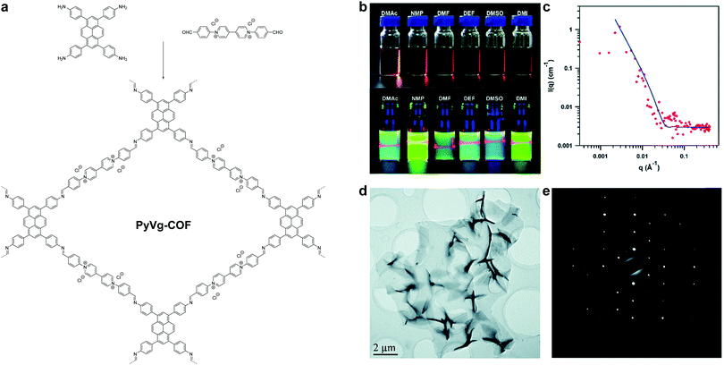 | ||
| Fig. 30 (a) Synthesis of PyVg-COF. (b) Photos of PyVy-COF dissolved in various solvents. Top: Concentrated solutions under sunlight; bottom: dilute solutions under 365 nm UV light showing the Tydall effect. (c) SANS of a DMSO-d6 solution containing concentrated PyVg-COF. (d) TEM image of PyVg-COFene. (e) SAED of PyVg-COFene. Reproduced with permission from ref. 54. Copyright 2019. Royal Society of Chemistry. | ||
In short, we have summarized the useful building units for construction of COFenes via the top-down approach (Fig. 31). These molecular scaffolds can reinforce the in-plane robustness of the 2D network or/and facilitate the delamination process by weakening the charge repulsion.
Early research in the bottom-up synthesis of COFenes mainly focused on the surface-assisted method, which was carried out in ultrahigh vacuum conditions for scanning tunneling microscopy imaging.136 However, only sub-micron sized small islands could be grown and the choice of linkers is limited. Herein, the useful building units for bottom-up synthesis of COFenes are summarized in Fig. 32.
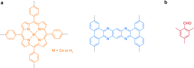 | ||
| Fig. 32 Useful molecular scaffolds for bottom-up synthesis of COFenes. (a) Backbone functionalities. (b) Inhibitor for crystal growth. | ||
In 2016, Feng et al. reported a wafer-scale porphyrin-based imine COFene prepared via the interface growth method (Fig. 33).137 By carrying out confined growth at the air–water or liquid–liquid interface, monolayer or multilayer COFenes were successfully prepared. The monolayer COFene displayed an AFM thickness of ∼0.7 nm, and its in-plane crystallinity was proved by SAED. The multilayer COFene displayed an AFM thickness of 20 nm, and its out-of-plane crystallinity was confirmed by TEM. Interestingly, the monolayer COFene exhibited a Young's modulus of 267 ± 30 GPa, which is comparable to the lower end boundary of graphene (200–1000 GPa). The thin film transistor fabricated using the monolayer COFene exhibited a mobility of 1.3 × 10⁻⁶ cm2 V−1 s−1 and an on/off ratio of 102. When doped with iodine, the mobility increased to 1.6 × 10⁻⁴ cm2 V−1 s−1.
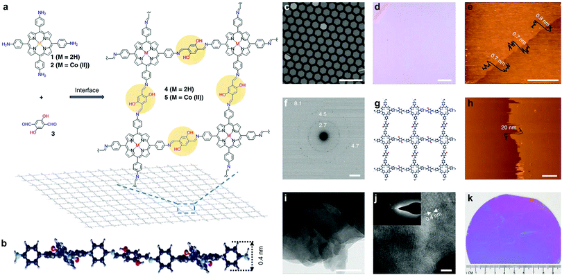 | ||
| Fig. 33 (a) Synthesis of the porphyrin-based COFene. (b) Cross-sectional view of the molecular structure of a monolayer COFene via density functional based tight binding (DFTB) calculations. (c) Scanning electron and (d) optical microscopic images of a monolayer COFene over a copper grid and deposited on a 300 nm silica substrate, respectively. (e) AFM image of the monolayer COFene on a silica substrate. (f) SAED pattern of the monolayer COFene sandwiched by two layers of graphene (G), G/COFene/G. (g) Molecular structure of the monolayer COFene via DFTB calculations. (h) AFM and (i and j) TEM images of a multilayer COFene. Inset in (j) SAED pattern. (k) Image of the monolayer COFene on a 4 inch 300 nm silica wafer. Scale bar, 100 μm (c); scale bar, 100 μm (d); scale bar, 3 μm (e); scale bar, 2 nm−1 (f); scale bar, 3 μm (h); scale bar, 50 nm (i); scale bar, 3 nm (j). Reproduced with permission from ref. 137. Copyright 2016. Nature Publishing Group. | ||
In 2017, our group demonstrated a highly conjugated COFene with C–C bond linkages (Fig. 34).138 Using the surface-assisted growth method and an Ulman coupling reaction, a C–C bonded COFene with brickwall topology was synthesized and imaged by STM. The material can also be prepared in the bulk form by crystallizing the “H” shaped monomers into a pre-packed molecular crystal, followed by solid-station polymerization. The bulk material exhibits eclipsed stacking suggested by the PXRD pattern, and can be mechanically exfoliated into micrometre-sized sheets with an AFM thickness of 1 nm. The highly conjugated structure and 1D open channels in the bulk material afford good electrical and ion conductivity. The material is useful as an anode material for sodium ion batteries, in which long-term cycling over 7700 cycles with retention of 70% of the initial capacity at a high current density of 5 A g−1 could be obtained.
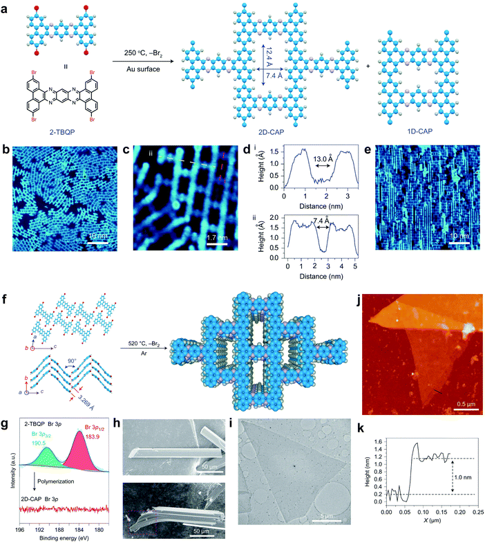 | ||
| Fig. 34 (a) Synthesis of COFene-CAP via metal-surface-mediated polymerization. (b) Single-layer CAP grown on an Au(111) surface. (c) Two misoriented 2D-CAP domains on an Au(111) surface. (d) Corresponding height profiles for the cross-sections i (pink) and ii (yellow) in (c). (e) Monolayer COFene-CAP grown on an Au(110) surface. (f) Bulk solid-state polymerization of the monomers pre-arranged in crystals. (g) XPS Br 3p spectra of 2-TBQP monomers and 2D-CAP. (h) SEM image of 2-TBQP crystals (up) and the as-prepared 2D-CAP crystals (down). (i) TEM image of an exfoliated 2D-CAP sheet. (j) AFM image of the exfoliated 2D-CAP on a silicon wafer. (k) AFM height profile of the cross-section in (j). Reproduced with permission from ref. 138. Copyright 2017. Nature Publishing Group. | ||
In 2018, Liu, Wang et al. reported an interface confinement method to prepare COFenes within a superspreading water layer.25 As shown in Fig. 35, the authors adopted a liquid/liquid/gel triphase system for the confined synthesis of COFenes. The amine linkers and aldehyde linkers were introduced into the hydrogel and oil phase, respectively, and diffused into the thin superspreading water layers between the oil and hydrogel phases to form the COFene thin film. Large area COF films with AFM thicknesses ranging from 4 to 150 nm were successfully prepared. Oriented crystallinity was verified using synchrotron radiation grazing incidence wide-angle X-ray scattering (GIWAXS). The Young's modulus of the COFene film measured by the AFM indentation method was 25.9 ± 0.6 GPa. The COFene film was able to generate ∼1.2 μA cm−2 photocurrent in a 0.1 M Na2SO4 solution with 0.5 mM ascorbic acid as an electron donor under white light irradiation. Using its photoelectrochemical (PEC) activity, the COFene film could detect Ru3+ selectively.
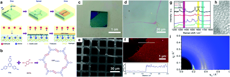 | ||
| Fig. 35 (a) Scheme of triphase confined synthesis of COFenes. (b) Synthesis of COFTTA-DHTA. (c) Photo image of the COFTTA-DHTA film on a silica wafer. (d) Optical microscopic image of the COFTTA-DHTA film. (e) SEM image of the COFTTA-DHTA film on TEM grids. (f) AFM height image of the COFTTA-DHTA film on a silica wafer. (g) Raman spectra of the COFTTA-DHTA film and powder, and the monomers. (h) TEM images of the COFTTA-DHTA film. Inset: SAED pattern of the films. (i) GIWAXS of the COFTTA-DHTA thin film. Reproduced with permission from ref. 25. Copyright 2018. American Chemical Society. | ||
Very recently, Kaiser, Zheng, Feng et al. reported a surfactant-assisted method to prepare porphyrin COFenes via imide or amide linkages (Fig. 36).26 Usually, preparation of polyimide COFs requires a base catalyst and high temperature due to the low reactivity and reversibility of the imide condensation reaction. In this work, aided by surfactant (sodium oleyl sulfate) monolayers, few-layer polyimide COFenes (2DPI) with a thickness of ∼2 nm and average crystal domain size of ∼3.5 μm2 were successfully prepared on the water surface by the reaction between amine and anhydride monomers at room temperature and under weak acidic conditions; GIWAXS and aberration-corrected HRTEM provided evidence for the good crystallinity of the COFene. The authors also reported the preparation of a polyamide COFene (2DPA) under similar conditions save for using trifluoromethanesulfonic acid as a catalyst. Interestingly, by changing the surfactant from sodium oleyl sulfate to stearic acid, they could switch the face-on configuration of the 2DPA COFene to edge-on-oriented multilayer COFs.
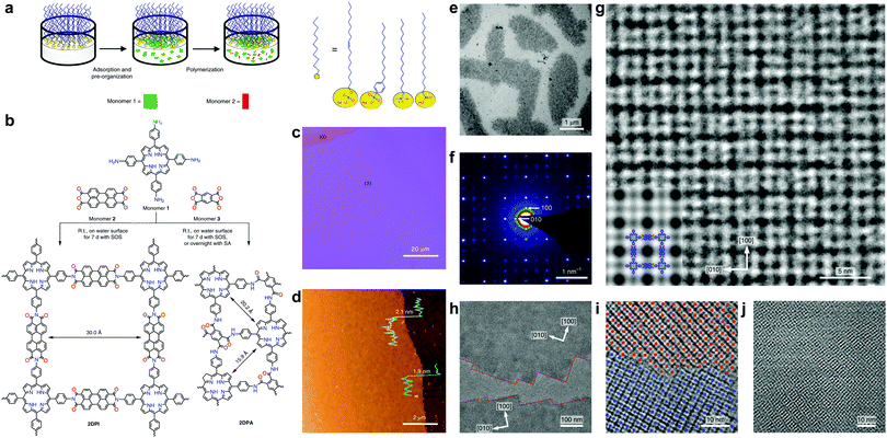 | ||
| Fig. 36 (a) A schematic of the synthetic procedure for preparation of COFenes 2DPI and 2DPA. (b) Reaction scheme of the COFene synthesis via a condensation reaction. (c) Optical microscope image of the 2DPI film, where (0) and (1) represent the uncovered substrate and film, respectively. (d) AFM image of the 2DPI film. (e) Bright-field TEM of the 2DPI film. (f) SAED pattern from the crystalline domain in (e). (g) AC-HRTEM image of 2DPI. Inset: A simulated image of 2DPI along the [001] projection with the structure model overlaid. (h) AC-HRTEM image of two crystalline domains, bridged by amorphous regions. (i) AC-HRTEM image of a tilt grain boundary. (j) AC-HRTEM image of an overlapping grain boundary exhibiting Moiré fringes. Reproduced with permission from ref. 26. Copyright 2019. Nature Publishing Group. | ||
In 2019, Jiang et al. reported a general synthetic method for the preparation of imine COFenes (Fig. 37).122 By using an excess amount of 2,4,6-trimethylbenzaldehyde (TBA) as a growth inhibitor, the axial π–π stacking of the COFenes was hindered, thereby allowing the anisotropic growth of the COF NSs along the planar directions to form few-layer COFenes. Based on this strategy, they produced five different COFenes using the solvothermal method, with various AFM thicknesses from 1.1 to 2.1 nm. Impressively, the SAED patterns of all the five COFenes exhibit sharp diffraction spots that reflect the good crystallinity of the COFenes. STM study revealed long-range order of porphyrin-based COFene-367. With [Ru(bpy)3]Cl2 as the photosensitizer and ascorbic acid as the electron donor, the porphyrin-based COFene shows excellent photocatalytic properties for CO2 reduction, with a CO production rate of 10![[thin space (1/6-em)]](https://www.rsc.org/images/entities/char_2009.gif) 162 μmol g−1 h−1 and a selectivity of ca. 78% in aqueous media under visible light irradiation.
162 μmol g−1 h−1 and a selectivity of ca. 78% in aqueous media under visible light irradiation.
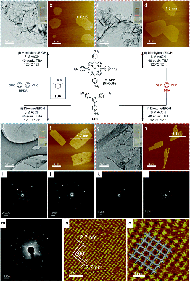 | ||
| Fig. 37 Bottom-up synthesis of COFenes. (a and b) COFene-367-Co. (c and d) COFene-366. (e and f) COFene TAPB-BPDA. (g and h) COFene TAPB-BDA. (a, c, e and g) TEM images. (b, d, f and h) AFM images. SAED patterns of (i) COFene-367-Co, (j) COFene-366, (k) COFene TAPB-BPDA, (l) COFene TAPB-BDA, and (m) COFene-367. (n) STM image of COFene-367. (o) Zoom-in STM image of COFene-367. Reproduced with permission from ref. 122. Copyright 2019. American Chemical Society. | ||
4. Conclusion
Chemists are drawn to the intellectual challenge of designing COFs from the bottom up, and to developing synthetic methodologies to make COFs with new topological structures and covalent linkages. Materials scientists examine the synthesized COF and evaluate its potential for application. Function-oriented design and synthesis of COFs require a truly multidisciplinary approach. In this review, we have analyzed the structures of 2D COFs in terms of their building blocks and linkages and correlated these to emerging applications in solid-state light emission, solvatochromism, gas storage, ion conduction and energy storage. Analysing the structure–property correlations for a large class of COFs provides useful guidance for the function-oriented synthesis of 2D COFs. Furthermore, we discuss the synthesis and properties of a new class of molecular 2D materials called COFenes, derived from the exfoliation of 2D COF thin sheets. The ability to fabricate COFene sheets with high in-plane crystallinity requires the structure and linkages of the parent COF to be robust. COFenes are solution-processible and can be restacked into lamellar films like graphene oxide, and thus they open up possibilities in many applications where processing issues prevented bulk COFs from being deployed.Conflicts of interest
There are no conflicts to declare.Acknowledgements
K. P. L. acknowledges NRF-CRP grant “Two-dimensional Covalent Organic Framework: Synthesis and Applications”. Grant number NRF-CRP16-2015-02, funded by National Research Foundation, Prime Minister's Office, Singapore.References
- B. M. Weckhuysen and J. Yu, Chem. Soc. Rev., 2015, 44, 7022–7024 RSC.
- M. S. N.-T. Mohau Moshoeshoe and V. Obuseng, Am. J. Mater. Sci., 2017, 7, 196–221 Search PubMed.
- M. D. Smith, E. J. Crace, A. Jaffe and H. I. Karunadasa, Annu. Rev. Mater. Res., 2018, 48, 111–136 CrossRef CAS.
- K. Leng, I. Abdelwahab, I. Verzhbitskiy, M. Telychko, L. Chu, W. Fu, X. Chi, N. Guo, Z. Chen, Z. Chen, C. Zhang, Q.-H. Xu, J. Lu, M. Chhowalla, G. Eda and K. P. Loh, Nat. Mater., 2018, 17, 908–914 CrossRef CAS PubMed.
- S. Qiu, M. Xue and G. Zhu, Chem. Soc. Rev., 2014, 43, 6116–6140 RSC.
- S. Yuan, L. Feng, K. Wang, J. Pang, M. Bosch, C. Lollar, Y. Sun, J. Qin, X. Yang, P. Zhang, Q. Wang, L. Zou, Y. Zhang, L. Zhang, Y. Fang, J. Li and H.-C. Zhou, Adv. Mater., 2018, 30, 1704303 CrossRef PubMed.
- X. Feng, X. Ding and D. Jiang, Chem. Soc. Rev., 2012, 41, 6010–6022 RSC.
- S.-Y. Ding and W. Wang, Chem. Soc. Rev., 2013, 42, 548–568 RSC.
- J. L. Segura, M. J. Mancheno and F. Zamora, Chem. Soc. Rev., 2016, 45, 5635–5671 RSC.
- C. S. Diercks and O. M. Yaghi, Science, 2017, 355, eaal1585 CrossRef PubMed.
- S. Kandambeth, K. Dey and R. Banerjee, J. Am. Chem. Soc., 2019, 141, 1807–1822 CrossRef CAS PubMed.
- J. L. Segura, S. Royuela and M. Mar Ramos, Chem. Soc. Rev., 2019, 48, 3903–3945 RSC.
- H. Wang, Z. Zeng, P. Xu, L. Li, G. Zeng, R. Xiao, Z. Tang, D. Huang, L. Tang, C. Lai, D. Jiang, Y. Liu, H. Yi, L. Qin, S. Ye, X. Ren and W. Tang, Chem. Soc. Rev., 2019, 48, 488–516 RSC.
- A. P. Côté, A. I. Benin, N. W. Ockwig, M. O'Keeffe, A. J. Matzger and O. M. Yaghi, Science, 2005, 310, 1166–1170 CrossRef PubMed.
- A. Eschenmoser, Helv. Chim. Acta, 2010, 93, 1439–1499 CrossRef CAS.
- D. Trauner, Angew. Chem., Int. Ed., 2017, 57, 4177–4191 CrossRef PubMed.
- I. Berlanga, M. L. Ruiz-Gonzalez, J. M. Gonzalez-Calbet, J. L. G. Fierro, R. Mas-Balleste and F. Zamora, Small, 2011, 7, 1207–1211 CrossRef CAS PubMed.
- S. Chandra, S. Kandambeth, B. P. Biswal, B. Lukose, S. M. Kunjir, M. Chaudhary, R. Babarao, T. Heine and R. Banerjee, J. Am. Chem. Soc., 2013, 135, 17853–17861 CrossRef CAS.
- Y. Peng, Y. Huang, Y. Zhu, B. Chen, L. Wang, Z. Lai, Z. Zhang, M. Zhao, C. Tan, N. Yang, F. Shao, Y. Han and H. Zhang, J. Am. Chem. Soc., 2017, 139, 8698–8704 CrossRef CAS PubMed.
- J. Sakamoto, J. van Heijst, O. Lukin and A. D. Schlüter, Angew. Chem., Int. Ed., 2009, 48, 1030–1069 CrossRef CAS PubMed.
- Z. Xiang, D. Cao and L. Dai, Polym. Chem., 2015, 6, 1896–1911 RSC.
- J. W. Colson, A. R. Woll, A. Mukherjee, M. P. Levendorf, E. L. Spitler, V. B. Shields, M. G. Spencer, J. Park and W. R. Dichtel, Science, 2011, 332, 228–231 CrossRef CAS PubMed.
- J. F. Dienstmaier, A. M. Gigler, A. J. Goetz, P. Knochel, T. Bein, A. Lyapin, S. Reichlmaier, W. M. Heckl and M. Lackinger, ACS Nano, 2011, 5, 9737–9745 CrossRef CAS PubMed.
- L. Xu, X. Zhou, Y. Yu, W. Q. Tian, J. Ma and S. Lei, ACS Nano, 2013, 7, 8066–8073 CrossRef CAS PubMed.
- Q. Hao, C. Zhao, B. Sun, C. Lu, J. Liu, M. Liu, L.-J. Wan and D. Wang, J. Am. Chem. Soc., 2018, 140, 12152–12158 CrossRef CAS PubMed.
- K. Liu, H. Qi, R. Dong, R. Shivhare, M. Addicoat, T. Zhang, H. Sahabudeen, T. Heine, S. Mannsfeld, U. Kaiser, Z. Zheng and X. Feng, Nat. Chem., 2019, 11, 994–1000 CrossRef CAS PubMed.
- K. S. Novoselov, A. K. Geim, S. V. Morozov, D. Jiang, Y. Zhang, S. V. Dubonos, I. V. Grigorieva and A. A. Firsov, Science, 2004, 306, 666 CrossRef CAS PubMed.
- M. Naguib, O. Mashtalir, J. Carle, V. Presser, J. Lu, L. Hultman, Y. Gogotsi and M. W. Barsoum, ACS Nano, 2012, 6, 1322–1331 CrossRef CAS PubMed.
- T.-Y. Zhou, S.-Q. Xu, Q. Wen, Z.-F. Pang and X. Zhao, J. Am. Chem. Soc., 2014, 136, 15885–15888 CrossRef CAS PubMed.
- S. Dalapati, E. Jin, M. Addicoat, T. Heine and D. Jiang, J. Am. Chem. Soc., 2016, 138, 5797–5800 CrossRef CAS PubMed.
- S. Dalapati, S. Jin, J. Gao, Y. Xu, A. Nagai and D. Jiang, J. Am. Chem. Soc., 2013, 135, 17310–17313 CrossRef CAS PubMed.
- S. Wan, J. Guo, J. Kim, H. Ihee and D. L. Jiang, Angew. Chem., Int. Ed., 2008, 47, 8826–8830 CrossRef CAS PubMed.
- L. Ascherl, T. Sick, J. T. Margraf, S. H. Lapidus, M. Calik, C. Hettstedt, K. Karaghiosoff, M. Döblinger, T. Clark, K. W. Chapman, F. Auras and T. Bein, Nat. Chem., 2016, 8, 310–316 CrossRef CAS.
- S. Wan, J. Guo, J. Kim, H. Ihee and D. L. Jiang, Angew. Chem., Int. Ed., 2009, 48, 5439–5442 CrossRef CAS PubMed.
- J. W. Crowe, L. A. Baldwin and P. L. McGrier, J. Am. Chem. Soc., 2016, 138, 10120–10123 CrossRef CAS PubMed.
- E. Jin, J. Li, K. Geng, Q. Jiang, H. Xu, Q. Xu and D. Jiang, Nat. Commun., 2018, 9, 4143 CrossRef.
- F. Auras, L. Ascherl, A. H. Hakimioun, J. T. Margraf, F. C. Hanusch, S. Reuter, D. Bessinger, M. Döblinger, C. Hettstedt, K. Karaghiosoff, S. Herbert, P. Knochel, T. Clark and T. Bein, J. Am. Chem. Soc., 2016, 138, 16703–16710 CrossRef CAS.
- E. L. Spitler, B. T. Koo, J. L. Novotney, J. W. Colson, F. J. Uribe-Romo, G. D. Gutierrez, P. Clancy and W. R. Dichtel, J. Am. Chem. Soc., 2011, 133, 19416–19421 CrossRef CAS PubMed.
- L. A. Baldwin, J. W. Crowe, M. D. Shannon, C. P. Jaroniec and P. L. McGrier, Chem. Mater., 2015, 27, 6169–6172 CrossRef CAS.
- G. Zhang, X. Li, Q. Liao, Y. Liu, K. Xi, W. Huang and X. Jia, Nat. Commun., 2018, 9, 2785 CrossRef.
- S.-Y. Ding, M. Dong, Y.-W. Wang, Y.-T. Chen, H.-Z. Wang, C.-Y. Su and W. Wang, J. Am. Chem. Soc., 2016, 138, 3031–3037 CrossRef CAS PubMed.
- X. Li, Q. Gao, J. Wang, Y. Chen, Z.-H. Chen, H.-S. Xu, W. Tang, K. Leng, G.-H. Ning, J. Wu, Q.-H. Xu, S. Y. Quek, Y. Lu and K. P. Loh, Nat. Commun., 2018, 9, 2335 CrossRef PubMed.
- X. Li, J. Qiao, S. W. Chee, H.-S. Xu, X. Zhao, H. S. Choi, W. Yu, S. Y. Quek, U. Mirsaidov and K. P. Loh, J. Am. Chem. Soc., 2020, 142, 4932–4943 CrossRef CAS PubMed.
- T. Jadhav, Y. Fang, W. Patterson, C.-H. Liu, E. Hamzehpoor and D. F. Perepichka, Angew. Chem., Int. Ed., 2019, 58, 13753–13757 CrossRef CAS PubMed.
- S. Wei, F. Zhang, W. Zhang, P. Qiang, K. Yu, X. Fu, D. Wu, S. Bi and F. Zhang, J. Am. Chem. Soc., 2019, 141, 14272–14279 CrossRef CAS PubMed.
- B.-K. An, D.-S. Lee, J.-S. Lee, Y.-S. Park, H.-S. Song and S. Y. Park, J. Am. Chem. Soc., 2004, 126, 10232–10233 CrossRef CAS PubMed.
- B. Wang, Y. Wang, J. Hua, Y. Jiang, J. Huang, S. Qian and H. Tian, Chem. – Eur. J., 2011, 17, 2647–2655 CrossRef CAS PubMed.
- P. Duan, N. Yanai, Y. Kurashige and N. Kimizuka, Angew. Chem., Int. Ed., 2015, 54, 7544–7549 CrossRef CAS PubMed.
- S.-J. Lim, B.-K. An and S. Y. Park, Macromolecules, 2005, 38, 6236–6239 CrossRef CAS.
- W. Jia, P. Yang, J. Li, Z. Yin, L. Kong, H. Lu, Z. Ge, Y. Wu, X. Hao and J. Yang, Polym. Chem., 2014, 5, 2282–2292 RSC.
- Y. Wei, W. Chen, X. Zhao, S. Ding, S. Han and L. Chen, Polym. Chem., 2016, 7, 3983–3988 RSC.
- H. Wu, Z. Chen, W. Chi, A. K. Bindra, L. Gu, C. Qian, B. Wu, B. Yue, G. Liu, G. Yang, L. Zhu and Y. Zhao, Angew. Chem., Int. Ed., 2019, 58, 11419–11423 CrossRef CAS PubMed.
- X. Wu, X. Han, Y. Liu, Y. Liu and Y. Cui, J. Am. Chem. Soc., 2018, 140, 16124–16133 CrossRef CAS PubMed.
- L. Wang, C. Zeng, H. Xu, P. Yin, D. Chen, J. Deng, M. Li, N. Zheng, C. Gu and Y. Ma, Chem. Sci., 2019, 10, 1023–1028 RSC.
- S. Wang, L. Ma, Q. Wang, P. Shao, D. Ma, S. Yuan, P. Lei, P. Li, X. Feng and B. Wang, J. Mater. Chem. C, 2018, 6, 5369–5374 RSC.
- Y. Gong, Y. Tan, H. Li, Y. Zhang, W. Yuan, Y. Zhang, J. Sun and B. Z. Tang, Sci. China: Chem., 2013, 56, 1183–1186 CrossRef CAS.
- P. Albacete, J. I. Martínez, X. Li, A. López-Moreno, S. A. Mena-Hernando, A. E. Platero-Prats, C. Montoro, K. P. Loh, E. M. Pérez and F. Zamora, J. Am. Chem. Soc., 2018, 140, 12922–12929 CrossRef CAS PubMed.
- G. Das, B. P. Biswal, S. Kandambeth, V. Venkatesh, G. Kaur, M. Addicoat, T. Heine, S. Verma and R. Banerjee, Chem. Sci., 2015, 6, 3931–3939 RSC.
- Q. Gao, X. Li, G.-H. Ning, K. Leng, B. Tian, C. Liu, W. Tang, H.-S. Xu and K. P. Loh, Chem. Commun., 2018, 54, 2349–2352 RSC.
- Z. Li, N. Huang, K. H. Lee, Y. Feng, S. Tao, Q. Jiang, Y. Nagao, S. Irle and D. Jiang, J. Am. Chem. Soc., 2018, 140, 12374–12377 CrossRef CAS PubMed.
- L. Stegbauer, K. Schwinghammer and B. V. Lotsch, Chem. Sci., 2014, 5, 2789–2793 RSC.
- W. Liu, Q. Su, P. Ju, B. Guo, H. Zhou, G. Li and Q. Wu, ChemSusChem, 2016, 10, 664–669 CrossRef PubMed.
- S. Haldar, D. Chakraborty, B. Roy, G. Banappanavar, K. Rinku, D. Mullangi, P. Hazra, D. Kabra and R. Vaidhyanathan, J. Am. Chem. Soc., 2018, 140, 13367–13374 CrossRef CAS PubMed.
- L. Zhang, S. Wang, Y. Zhou, C. Wang, X.-Z. Zhang and H. Deng, Angew. Chem., 2019, 131, 14351–14356 CrossRef.
- A. M. Kaczmarek, Y.-Y. Liu, M. K. Kaczmarek, H. Liu, F. Artizzu, L. D. Carlos and P. Van Der Voort, Angew. Chem., 2020, 59, 1932–1940 CrossRef CAS PubMed.
- Q. Fang, J. Wang, S. Gu, R. B. Kaspar, Z. Zhuang, J. Zheng, H. Guo, S. Qiu and Y. Yan, J. Am. Chem. Soc., 2015, 137, 8352–8355 CrossRef CAS PubMed.
- L. Bai, S. Z. F. Phua, W. Q. Lim, A. Jana, Z. Luo, H. P. Tham, L. Zhao, Q. Gao and Y. Zhao, Chem. Commun., 2016, 52, 4128–4131 RSC.
- S. Mitra, H. S. Sasmal, T. Kundu, S. Kandambeth, K. Illath, D. Díaz Díaz and R. Banerjee, J. Am. Chem. Soc., 2017, 139, 4513–4520 CrossRef CAS PubMed.
- W. Huang, Y. Jiang, X. Li, X. Li, J. Wang, Q. Wu and X. Liu, ACS Appl. Mater. Interfaces, 2013, 5, 8845–8849 CrossRef CAS PubMed.
- G.-H. Ning, Z. Chen, Q. Gao, W. Tang, Z. Chen, C. Liu, B. Tian, X. Li and K. P. Loh, J. Am. Chem. Soc., 2017, 139, 8897–8904 CrossRef CAS PubMed.
- X. Li, Q. Gao, J. Aneesh, H.-S. Xu, Z. Chen, W. Tang, C. Liu, X. Shi, K. V. Adarsh, Y. Lu and K. P. Loh, Chem. Mater., 2018, 30, 5743–5749 CrossRef CAS.
- S. Jhulki, A. M. Evans, X.-L. Hao, M. W. Cooper, C. H. Feriante, J. Leisen, H. Li, D. Lam, M. C. Hersam, S. Barlow, J.-L. Brédas, W. R. Dichtel and S. R. Marder, J. Am. Chem. Soc., 2020, 142, 783–791 CrossRef CAS PubMed.
- M. D. Cohen, S. Flavian and L. Leiserowitz, J. Chem. Soc. B, 1967, 329–334, 10.1039/J29670000329.
- K. Ogawa, Y. Kasahara, Y. Ohtani and J. Harada, J. Am. Chem. Soc., 1998, 120, 7107–7108 CrossRef CAS.
- J. Harada, H. Uekusa and Y. Ohashi, J. Am. Chem. Soc., 1999, 121, 5809–5810 CrossRef CAS.
- L. Ascherl, E. W. Evans, M. Hennemann, D. Di Nuzzo, A. G. Hufnagel, M. Beetz, R. H. Friend, T. Clark, T. Bein and F. Auras, Nat. Commun., 2018, 9, 3802 CrossRef PubMed.
- N. Huang, X. Ding, J. Kim, H. Ihee and D. Jiang, Angew. Chem., Int. Ed., 2015, 54, 8704–8707 CrossRef CAS PubMed.
- F. Yu, W. Liu, B. Li, D. Tian, J.-L. Zuo and Q. Zhang, Angew. Chem., Int. Ed., 2019, 58, 16101–16104 CrossRef CAS PubMed.
- J. Harada, K. Ogawa and S. Tomoda, Acta Crystallogr., Sect. B: Struct. Sci., 1997, 53, 662–672 CrossRef.
- G. Das, T. Prakasam, M. A. Addicoat, S. K. Sharma, F. Ravaux, R. Mathew, M. Baias, R. Jagannathan, M. A. Olson and A. Trabolsi, J. Am. Chem. Soc., 2019, 141, 19078–19087 CrossRef CAS PubMed.
- R. V. Siriwardane, M.-S. Shen, E. P. Fisher and J. Losch, Energy Fuels, 2005, 19, 1153–1159 CrossRef CAS.
- J. C. Fisher, R. V. Siriwardane and R. W. Stevens, Ind. Eng. Chem. Res., 2011, 50, 13962–13968 CrossRef CAS.
- Y. Zeng, R. Zou and Y. Zhao, Adv. Mater., 2016, 28, 2855–2873 CrossRef CAS PubMed.
- L. Zou, Y. Sun, S. Che, X. Yang, X. Wang, M. Bosch, Q. Wang, H. Li, M. Smith, S. Yuan, Z. Perry and H.-C. Zhou, Adv. Mater., 2017, 29, 1700229 CrossRef PubMed.
- N. Huang, P. Wang and D. Jiang, Nat. Rev. Mater., 2016, 1, 16068 CrossRef CAS.
- M. S. Lohse and T. Bein, Adv. Funct. Mater., 2018, 28, 1705553 CrossRef.
- F. Zhao, H. Liu, D. R. S. Mathe, A. Dong and J. Zhang, Nanomaterials, 2018, 8, 15 CrossRef PubMed.
- S. Karak, S. Kandambeth, B. P. Biswal, H. S. Sasmal, S. Kumar, P. Pachfule and R. Banerjee, J. Am. Chem. Soc., 2017, 139, 1856–1862 CrossRef CAS PubMed.
- Q. Gao, X. Li, G.-H. Ning, H.-S. Xu, C. Liu, B. Tian, W. Tang and K. P. Loh, Chem. Mater., 2018, 30, 1762–1768 CrossRef CAS.
- S. Lin, C. S. Diercks, Y.-B. Zhang, N. Kornienko, E. M. Nichols, Y. Zhao, A. R. Paris, D. Kim, P. Yang, O. M. Yaghi and C. J. Chang, Science, 2015, 349, 1208–1213 CrossRef CAS PubMed.
- H.-J. Zhu, M. Lu, Y.-R. Wang, S.-J. Yao, M. Zhang, Y.-H. Kan, J. Liu, Y. Chen, S.-L. Li and Y.-Q. Lan, Nat. Commun., 2020, 11, 497 CrossRef CAS PubMed.
- Z. Meng, R. M. Stolz and K. A. Mirica, J. Am. Chem. Soc., 2019, 141, 11929–11937 CrossRef CAS PubMed.
- X. Li, H. Wang, Z. Chen, H.-S. Xu, W. Yu, C. Liu, X. Wang, K. Zhang, K. Xie and K. P. Loh, Adv. Mater., 2019, 31, 1905879 CrossRef CAS PubMed.
- S. Yang, W. Hu, X. Zhang, P. He, B. Pattengale, C. Liu, M. Cendejas, I. Hermans, X. Zhang, J. Zhang and J. Huang, J. Am. Chem. Soc., 2018, 140, 14614–14618 CrossRef CAS PubMed.
- M. Lu, J. Liu, Q. Li, M. Zhang, M. Liu, J.-L. Wang, D.-Q. Yuan and Y.-Q. Lan, Angew. Chem., Int. Ed., 2019, 58, 12392–12397 CrossRef CAS PubMed.
- Z. Fu, X. Wang, A. M. Gardner, X. Wang, S. Y. Chong, G. Neri, A. J. Cowan, L. Liu, X. Li, A. Vogel, R. Clowes, M. Bilton, L. Chen, R. S. Sprick and A. I. Cooper, Chem. Sci., 2020, 11, 543–550 RSC.
- W. Zhong, R. Sa, L. Li, Y. He, L. Li, J. Bi, Z. Zhuang, Y. Yu and Z. Zou, J. Am. Chem. Soc., 2019, 141, 7615–7621 CrossRef CAS PubMed.
- Y. Wang, A. L. Agapov, F. Fan, K. Hong, X. Yu, J. Mays and A. P. Sokolov, Phys. Rev. Lett., 2012, 108, 088303 CrossRef PubMed.
- J. Lopez, D. G. Mackanic, Y. Cui and Z. Bao, Nat. Rev. Mater., 2019, 4, 312–330 CrossRef CAS.
- X. Li and K. P. Loh, ACS Mater. Lett., 2019, 1, 327–335 CrossRef CAS.
- K. A. Mauritz and R. B. Moore, Chem. Rev., 2004, 104, 4535–4586 CrossRef CAS PubMed.
- M. A. Hickner, H. Ghassemi, Y. S. Kim, B. R. Einsla and J. E. McGrath, Chem. Rev., 2004, 104, 4587–4612 CrossRef CAS PubMed.
- S. J. Paddison, Annu. Rev. Mater. Res., 2003, 33, 289–319 CrossRef CAS.
- H. Xu, S. Tao and D. Jiang, Nat. Mater., 2016, 15, 722–726 CrossRef CAS PubMed.
- C. Montoro, D. Rodríguez-San-Miguel, E. Polo, R. Escudero-Cid, M. L. Ruiz-González, J. A. R. Navarro, P. Ocón and F. Zamora, J. Am. Chem. Soc., 2017, 139, 10079–10086 CrossRef CAS.
- S. Chandra, T. Kundu, S. Kandambeth, R. BabaRao, Y. Marathe, S. M. Kunjir and R. Banerjee, J. Am. Chem. Soc., 2014, 136, 6570–6573 CrossRef CAS PubMed.
- S. Chandra, T. Kundu, K. Dey, M. Addicoat, T. Heine and R. Banerjee, Chem. Mater., 2016, 28, 1489–1494 CrossRef CAS.
- S. Sasmal Himadri, B. Aiyappa Harshitha, N. Bhange Siddheshwar, S. Karak, A. Halder, S. Kurungot and R. Banerjee, Angew. Chem., Int. Ed., 2018, 57, 10894–10898 CrossRef PubMed.
- Y. Yang, X. He, P. Zhang, Y. H. Andaloussi, H. Zhang, Z. Jiang, Y. Chen, S. Ma, P. Cheng and Z. Zhang, Angew. Chem., Int. Ed., 2020, 59, 3678–3684 CrossRef CAS PubMed.
- H. Ma, B. Liu, B. Li, L. Zhang, Y.-G. Li, H.-Q. Tan, H.-Y. Zang and G. Zhu, J. Am. Chem. Soc., 2016, 138, 5897–5903 CrossRef CAS PubMed.
- Y. Peng, G. Xu, Z. Hu, Y. Cheng, C. Chi, D. Yuan, H. Cheng and D. Zhao, ACS Appl. Mater. Interfaces, 2016, 8, 18505–18512 CrossRef CAS PubMed.
- D. B. Shinde, H. B. Aiyappa, M. Bhadra, B. P. Biswal, P. Wadge, S. Kandambeth, B. Garai, T. Kundu, S. Kurungot and R. Banerjee, J. Mater. Chem. A, 2016, 4, 2682–2690 RSC.
- Z. Meng, A. Aykanat and K. A. Mirica, Chem. Mater., 2019, 31, 819–825 CrossRef CAS.
- K. C. Ranjeesh, R. Illathvalappil, S. D. Veer, J. Peter, V. C. Wakchaure, Goudappagouda, K. V. Raj, S. Kurungot and S. S. Babu, J. Am. Chem. Soc., 2019, 141, 14950–14954 CrossRef CAS PubMed.
- M. Chhowalla, H. S. Shin, G. Eda, L.-J. Li, K. P. Loh and H. Zhang, Nat. Chem., 2013, 5, 263–275 CrossRef PubMed.
- P. Miro, M. Audiffred and T. Heine, Chem. Soc. Rev., 2014, 43, 6537–6554 RSC.
- X. Feng, L. Chen, Y. Honsho, O. Saengsawang, L. L. Liu, L. Wang, A. Saeki, S. Irle, S. Seki, Y. P. Dong and D. L. Jiang, Adv. Mater., 2012, 24, 3026–3031 CrossRef CAS PubMed.
- X. Feng, L. Liu, Y. Honsho, A. Saeki, S. Seki, S. Irle, Y. Dong, A. Nagai and D. Jiang, Angew. Chem., Int. Ed., 2012, 51, 2618–2622 CrossRef CAS PubMed.
- M. A. Springer, T.-J. Liu, A. Kuc and T. Heine, Chem. Soc. Rev., 2020, 49, 2007–2019 RSC.
- J. Dong, X. Li, K. Zhang, Y. Di Yuan, Y. Wang, L. Zhai, G. Liu, D. Yuan, J. Jiang and D. Zhao, J. Am. Chem. Soc., 2018, 140, 4035–4046 CrossRef CAS PubMed.
- S. Wu, M. Li, H. Phan, D. Wang, T. S. Herng, J. Ding, Z. Lu and J. Wu, Angew. Chem., Int. Ed., 2018, 57, 8007–8011 CrossRef CAS PubMed.
- W. Liu, X. Li, C. Wang, H. Pan, W. Liu, K. Wang, Q. Zeng, R. Wang and J. Jiang, J. Am. Chem. Soc., 2019, 141, 17431–17440 CrossRef CAS PubMed.
- S. Royuela, E. Martínez-Periñán, M. P. Arrieta, J. I. Martínez, M. M. Ramos, F. Zamora, E. Lorenzo and J. L. Segura, Chem. Commun., 2020, 56, 1267–1270 RSC.
- K. P. Loh, Q. Bao, G. Eda and M. Chhowalla, Nat. Chem., 2010, 2, 1015–1024 CrossRef CAS PubMed.
- Y. Li, Q. Wu, X. Guo, M. Zhang, B. Chen, G. Wei, X. Li, X. Li, S. Li and L. Ma, Nat. Commun., 2020, 11, 599 CrossRef CAS PubMed.
- G. Liu, W. Jin and N. Xu, Chem. Soc. Rev., 2015, 44, 5016–5030 RSC.
- M. Dogru, M. Handloser, F. Auras, T. Kunz, D. Medina, A. Hartschuh, P. Knochel and T. Bein, Angew. Chem., Int. Ed., 2013, 52, 2920–2924 CrossRef CAS PubMed.
- M. Dogru, A. Sonnauer, S. Zimdars, M. Doblinger, P. Knochel and T. Bein, CrystEngComm, 2013, 15, 1500–1502 RSC.
- M. Calik, F. Auras, L. M. Salonen, K. Bader, I. Grill, M. Handloser, D. D. Medina, M. Dogru, F. Löbermann, D. Trauner, A. Hartschuh and T. Bein, J. Am. Chem. Soc., 2014, 136, 17802–17807 CrossRef CAS PubMed.
- J. Guo, Y. Xu, S. Jin, L. Chen, T. Kaji, Y. Honsho, M. A. Addicoat, J. Kim, A. Saeki, H. Ihee, S. Seki, S. Irle, M. Hiramoto, J. Gao and D. Jiang, Nat. Commun., 2013, 4, 2736 CrossRef PubMed.
- V. A. Kuehl, J. Yin, P. H. H. Duong, B. Mastorovich, B. Newell, K. D. Li-Oakey, B. A. Parkinson and J. O. Hoberg, J. Am. Chem. Soc., 2018, 140, 18200–18207 CrossRef CAS PubMed.
- B. Zhang, M. Wei, H. Mao, X. Pei, S. A. Alshmimri, J. A. Reimer and O. M. Yaghi, J. Am. Chem. Soc., 2018, 140, 12715–12719 CrossRef CAS PubMed.
- X. Guan, H. Li, Y. Ma, M. Xue, Q. Fang, Y. Yan, V. Valtchev and S. Qiu, Nat. Chem., 2019, 11, 587–594 CrossRef CAS PubMed.
- D. N. Bunck and W. R. Dichtel, J. Am. Chem. Soc., 2013, 135, 14952–14955 CrossRef CAS PubMed.
- A. Mal, K. Mishra Rakesh, K. Praveen Vakayil, M. A. Khayum, R. Banerjee and A. Ajayaghosh, Angew. Chem., Int. Ed., 2018, 57, 8443–8447 CrossRef CAS PubMed.
- D. Cui, D. F. Perepichka, J. M. MacLeod and F. Rosei, Chem. Soc. Rev., 2020, 49, 2020–2038 RSC.
- H. Sahabudeen, H. Qi, B. A. Glatz, D. Tranca, R. Dong, Y. Hou, T. Zhang, C. Kuttner, T. Lehnert, G. Seifert, U. Kaiser, A. Fery, Z. Zheng and X. Feng, Nat. Commun., 2016, 7, 13461 CrossRef CAS PubMed.
- W. Liu, X. Luo, Y. Bao, Y. P. Liu, G.-H. Ning, I. Abdelwahab, L. Li, C. T. Nai, Z. G. Hu, D. Zhao, B. Liu, S. Y. Quek and K. P. Loh, Nat. Chem., 2017, 9, 563–570 CrossRef CAS PubMed.
| This journal is © The Royal Society of Chemistry 2020 |


