Covalent organic framework nanosheets: preparation, properties and applications
D.
Rodríguez-San-Miguel
 a,
C.
Montoro
 b and
F.
Zamora
 *bcd
*bcd
aDepartment of Chemistry and Applied Biosciences, Institute for Chemical and Bioengineering, ETH Zurich, Vladimir Prelog Weg 1, 8093 Zurich, Switzerland
bDepartamento de Química Inorgánica, Universidad Autónoma de Madrid, 28049 Madrid, Spain. E-mail: felix.zamora@uam.es
cCondensed Matter Physics Center (IFIMAC), Universidad Autónoma de Madrid, 28049 Madrid, Spain
dInstitute for Advanced Research in Chemical Sciences (IAdChem), Universidad Autónoma de Madrid, 28049 Madrid, Spain
First published on 17th March 2020
Abstract
Covalent organic frameworks (COFs) are crystalline and porous materials with bi- or three-dimensional structures built up by connecting their molecular precursors by dynamic covalent bonds. Using bottom-up or top-down strategies, bi-dimensional COFs can be obtained as single- or few-layer materials, thus enlarging the family of 2D-materials based on graphene. The main advantage of 2D-materials based on COFs is the fact that they can be chemically designed, thus allowing the formation of á la carte materials with well-designed functionalities including their size and features of their pores. The aim of this perspective review is to illustrate in a rational way the current state-of-the-art in the field of COF nanosheet formation using the two general approaches of material nano-structuring. This article reviews a selected collection of samples that illustrates the essential concepts, strategies of preparation following the two general approaches, bottom-up and top-down, and a selection of COF nanolayers showing seminal properties and potential material applications. Finally, we provide some perspectives of this novel research field.
Key learning points(1) 2D materials are new nanomaterials with two dimensions much larger, two orders of magnitude, than the other, the thickness.(2) Covalent Organic Frameworks, COFs, are porous designable materials, formed by the covalent assembly of molecular precursors, which are suitable sources of chemically designable 2D materials. (3) Top-down methods based on different types of exfoliation are suitable to produce colloids or powders of COF nanosheets. (4) Assembly of molecules under well-controlled conditions produces single or few layer COFs. (5) COF-nanolayers provide examples of their promising potential. |
1. Introduction
The field of nanomaterials science deals with the study of materials with at least one dimension within the nanoscale range. At this small scale, significant changes in physical and/or chemical properties may occur due to confinement effects, enhancement of surface area and structural effects due to the grain boundaries of the nanoparticles formed: for instance, size-effect properties such as surface plasmon resonance in metal nanoparticles, quantum confinement in semiconductor particles or superparamagnetism in magnetic nanoparticles. Thus, when the growth of a material is limited in all its dimensions within the range of tens of nanometers, a 0D nanomaterial, named a nanoparticle, is obtained, while when its growth is restricted in two dimensions in the nanoscale range, a wired or 1D material is obtained. Nevertheless, when just a dimension is limited to tens of nanometers, layers or 2D-materials are formed.Graphene represents the first 2D material isolated. Since its discovery and the characterization of its fascinating physical properties, the 2D material research field has gained increasing attention. Thus, during the last 10 years new 2D materials have been discovered. Currently, we can classify 2D materials in different sub-families: (i) elements, known as Xenes, such as graphene, phosphorene and antimonene; (ii) nitrides (h-BN, GaN, Ca2N,…); (iii) transition metal carbides, known as MXenes; (iv) transition metal dichalcogenides, and, more recently, (v) the families of porous layered materials: metal–organic and covalent organic frameworks, MOFs and COFs, respectively.
NCOFs are compounds with extended atomic structures in two or three dimensions, formed by combination of initial building blocks that are joined in dynamic processes, allowing the formation of the most thermodynamically stable product of the reaction. An important factor determining crystallinity in COFs is the dynamic nature of the bonds used to join the building blocks. This feature allows self-healing and error correction of the structures during synthesis. This concept is named “chemically induced reversibility”.1 Therefore, these processes give rise to the formation of crystalline structures. The reactions leading to COF formation are limited to those fulfilling the reversible character required to allow the formation of ordered structures. Indeed, this is the main structural difference between ordered organic polymers known as COFs and classical organic polymers formed using just strong and irreversible covalent bonds, such as C–C bonds.
In addition to their well-ordered structures, COFs display pores whose size and chemical features can be designed based on the selection of the initial building blocks. Then, COFs are defined as a family of organic polymers designed as ordered mesoporous materials based on the assembly of organic molecular precursors by means of reversible covalent bonds. The most typical dynamic covalent bonds are involved in condensation reactions.2 The two main groups of condensation reactions are: (i) boron based COFs formed by either self-condensation reactions of boronic acids3 or their condensation with catechols, giving rise to boronate esters; and (ii) nitrogen-based COFs or Schiff-base COFs which are in many cases chemically robust to many harsh conditions.4
Based on their ordered structures and porous nature, the potential applications suggested for COFs are gas adsorption, storage and separation5 and renewable energy applications.6 COFs have also been explored for use as catalysts7 and sensors8 as well as for the fabrication of electronic devices.9
Importantly, attending to aspects concerning basic materials science concepts, it was pointed out that in addition to the formation of bulk morphologies, COFs are excellent materials to produce free-standing nanolayers and single-layers on surfaces.10 Therefore, the inclusion of COFs and MOFs in the 2D-material family has allowed the incorporation of the concepts of modular chemistry and the preparation of new 2D molecular designed structures based on the self-assembly of molecular building blocks. The chemically programmed structures of 2D-materials based on COFs are unique because they are chemically and thermally robust, their optical and electronic properties can be fine-tuned, and, at the same time, they possess accessible functionalization sites, resulting in novel nanomaterials with potential applications in many emerging fields.
In this Tutorial Review, we aim to introduce and discuss the most relevant and promising processing methodologies for the preparation of COF nanosheets, named CONs, highlighting the most significant advances in production methods and characterization techniques and properties. Finally, some selected examples in which these processing methods have been successfully used to integrate CONs into prototype devices will be discussed.
2. Preparation methods
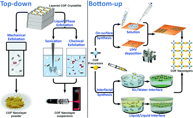
CONs can be obtained following top-down or bottom-up approaches (Fig. 1). Since CONs are derivatives of COFs, their preparation benefits from the general knowledge about COF synthesis (i.e. top-down approaches rely on standard COF synthetic procedures to obtain the starting COF material), but also faces the same challenges (i.e. the conditions used in bottom-up approaches have to allow the reversibility of COF linkage formation). An additional difficulty generally faced in the preparation of CONs is confirming that a structure analogous to the parent COF but with just a few layers has been obtained, since the two most used techniques to characterize bulk COFs (i.e. powder X-ray diffraction and N2 sorption isotherms) many times fail to provide useful information with the low amount of CONs available for analysis. The main differences between top-down and bottom-up strategies, the different methodologies derived from them and the characterization techniques employed are described below.2.1 Top-down
In order to exfoliate a layered crystal, it is necessary to apply external forces that will lead to the disintegration of the bulk structure with the formation of single- or multi-layers showing large lateral dimensions and the smallest thickness possible. Micromechanical exfoliation (MME) and liquid phase exfoliation (LPE) are the most common strategies so far used to exfoliate layered materials including COFs (Fig. 1).In this sense, the selection of an intercalating agent, good solvent or more specific molecules such as surfactants, which are able to prevent inter-layer re-aggregation, are parameters to take into account.
Thus, the main problem of LPE is to optimize all the experimental parameters to obtain single- or few-layers with large enough lateral dimensions to ensure long-range periodicity.
In the last few years, the search for 2D-polymers has attracted increasing attention.12 Although some of the 2D organic polymers do not show crystallinity and, therefore, they cannot be named COFs, they may show porosity, and eventually can also be exfoliated into nanosheets with nanometer thickness.13,14
The chemical compositions and structures of most of the COFs suggest the use of organic solvents for the LPE process because they seem to be suitable to disrupt the interlayer interactions, giving rise to nanosheets in stable suspensions or colloids. The first example of CONs prepared by LPE was reported in 2011 for the boronate ester linked COF-8.15 CONs were obtained by simply sonicating previously synthesized laminar crystallites of COF-8 in dichloromethane and centrifuging the resulting suspension to eliminate large sized aggregates. In order to characterize the CONs, the obtained diluted suspension was drop cast on a substrate, such as silicon dioxide or mica, affording isolated nanosheets. This allowed the use of atomic force microscopy (AFM) to quantify the level of exfoliation achieved, which in this case was a thickness of the CONs of 4 nm, corresponding to approximately 10 layers. The so-formed layers show lateral dimensions over several microns. Additionally, transmission electron microscopy (TEM) was performed on drop-cast samples. The images showed periodic fringes with distances matching the characteristic pore size and interlayer distances of COF-8 (Fig. 2). X-ray photoelectron spectroscopy (XPS) was also employed to chemically characterize the CONs and confirmed that the LPE process had not affected the chemical structure of the COF. These techniques have become commonplace for the characterization of CONs, and together with grazing incidence X-ray diffraction (GIXRD) constitute the basic set of tools for their study.
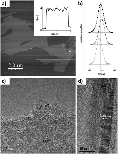 | ||
| Fig. 2 (a) AFM image of COF-8 nanolayers. The inset shows the height profile measured along the line in the image. (b) B(1s) core-level spectra of bulk COF-8 (top), boronic acid (middle), and the sonicated sample (bottom). TEM images showing (c) pores and (d) graphite like layers. Reproduced from ref. 15 with permission from Wiley-VCH, copyright 2011. | ||
In a further study, the exfoliation of a family of polyacetylenic porous layered COFs with different pore sizes, ranging from 1.4 to 3.2 nm, was explored using sonication. The AFM analysis of the isolated CONs showed that the degree of exfoliation depends on the polymer structure. Thus, COFs with smaller pores can be exfoliated to a higher degree than those with larger pores, although single layers were not obtained in any case. Even though it could be assumed that, in COFs with larger pores, the interlayer interactions are smaller and they should be more easily exfoliated, the mechanical stability of the framework is another important factor playing a role in the minimum thickness of the CONs obtained by ultrasonication. As COF layers with larger pores have a lower density of covalent bonds holding them together, extremely thin CONs have very low stability, and the sonication is able to break even the in-plane bonds of the material.16
Imine-linked COFs, those with higher chemical stability, are more promising for applications, and have also been exfoliated following the same methodology.17 The level of exfoliation is similar in this case, with the thickness of CONs being close to 3.5 nm (roughly 9 layers). Remarkably, it was shown that COFs with nonplanar building blocks can be more easily exfoliated. This is due to the fact that the layers of highly planar COFs can pack more tightly, increasing the interlayer π–π stacking interactions.
While sonication is an effective way of generating CONs, it is also a source of defects, since the high shear forces induced locally by cavitation can potentially break the covalent bonds within the layers. For this reason, milder LPE strategies have been developed.
Exploiting the decrease in the strength of interlayer interactions with the increasing curvature of the framework, Banerjee et al. reported a method for the generation of CONs through chemical exfoliation.18 A keto-enamine linked COF with anthracene moieties was made to react with N-hexylmaleimide (Fig. 3). The adduct formed by the Diels–Alder reaction between the maleimide and the anthracene not only distorts the planarity of the framework, but also results in the covalent anchoring of bulky groups on both sides of each COF layer. Both the distortion and the steric hindrance prevent efficient π–π stacking interactions between the layers. As a result, the resulting material from the reaction is readily exfoliated in organic solvents, yielding CONs without the use of sonication.
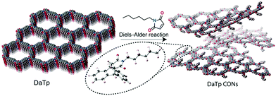 | ||
| Fig. 3 Schematic representation of the chemical exfoliation process by layer planarity distortion with the Diels–Alder reaction. Inset: Energy-optimized structure of the cycloadduct of N-hexylmaleimide and anthracene. Reproduced from ref. 18 with permission from Wiley-VCH, copyright 2016. | ||
Another chemical design that enables easy exfoliation of COFs is that of guanidinium-linked COFs.19 Due to the cationic guanidinium moieties in the structure, instead of attractive interactions between layers, there are repulsive electrostatic forces. Because of the layers being electrostatically charged, the bulk material is easily dispersed into CONs when dissolved in water.
Graphene was first isolated by Prof. Geim et al. in 2004 using the Scotch tape method of micromechanical exfoliation.20 This simple technique consists of the use of adhesive tape which is pressed against a laminar crystal so that some of the top layers are attached to the adhesive tape, then the tape with crystals of layered material is pressed against a surface of choice. The process can be done several times to reduce the thickness of the layers so-formed. Finally, upon peeling off, the bottom layer is left on the selected substrate. The interlayer energies of the laminar crystal should be weak, in the range of 4–70 meV, to enable the facile exfoliation of these layers.21 Despite the simplicity of the cleaving method, it has been largely used for fundamental studies. However, it presents several important drawbacks such as the very low yield of monolayers and the high cost, thus it is not technologically applicable. This method has also been used for other layered materials such as BN, MoS2, NbSe2, Bi2Sr2CaCu2Ox and more recently MOFs.22
In the case of COFs, mechanical exfoliation is by far less common than LPE, since the optimal substrate for this approach is large crystals of layered materials, and 2D COF crystallites are seldom bigger than 100 nm. The first example of CONs was reported by Benerjee et al. They used mechanochemical synthesis to prepare a series of isoreticular COFs.23 Although mechanochemical synthesis cannot be properly considered as mechanical exfoliation, subsequently the same group delaminated a series of keto-enamine-linked COFs.24 For that, they carried out mechanical grinding of the COF in a mortar with a few drops of a suitable solvent, which resulted in a material that could be easily dispersed in solvents. TEM and AFM measurements of these CONs revealed that the sheets had lateral sizes close to 1 μm and thicknesses between 3 and 10 nm.
In principle, mechanical grinding can be automated, being more reproducible, by the use of a ball mill instead of a manual mortar and pestle. In this sense, Wang et al. prepared CONs with thicknesses of 3–5 nm (10–15 layers) by the delamination of an anthraquinone based COF with a ball-milling device.25 In particular, vibratory ball milling was applied to the COF placed in a milling pot at room temperature and without additional exfoliating agents. Moreover, in order to control the nanosheet thickness, different vibration frequencies and times were applied.
In order to establish a general comparison between the two top-down procedures to generate CONs, MME and LPE, we have to make clear that (i) both approaches produce nanolayers with comparable dimensions, hundreds of nanometres in lateral dimensions by few nanometres in thickness; (ii) both are scale-up procedures, with the use of ball-milling techniques, however, being more efficient; (iii) MME produces CONs in the solid state, while LPE gives rise to suspensions or colloids; and (iv) MME is safer and greener than LPE, i.e. avoid the use of solvents.
2.2 Bottom-up
The bottom-up approach is the most conventional strategy used for the preparation of well-ordered molecular nanostructures since it allows the control of both the domain sizes and defects (Fig. 1). It consists of the effective diffusion, reorganization and assembly of the building blocks to give rise to the formation of 2D covalent networks through different chemical reactions such as boronic acid dehydration, esterification, boronate or Schiff-base formation. This strategy can be applied on the surface or at the air/water or liquid/liquid interface.2.2.1.1 Preparation under UHV conditions. On-surface mediated synthesis under ultrahigh vacuum (UHV) conditions (∼10−10 mbar) allows the formation of single-layered COFs (SCOFs) on metallic surfaces in an ultraclean environment. In comparison with solution synthesis, it can reach very high temperatures without air oxidation or solvent decomposition.
Moreover, this method is applied to rigid molecules capable of sublimation, favouring the preparation of CONs with organic molecules insoluble in any type of solvent. However, the main drawback is that the continuous desorption of the by-products generated in the reaction (usually water) makes the reactions carried out under these conditions irreversible, thus hindering the correction of defects and precluding long-range order. The covalently bonded nanoporous surface networks generated at both atomic and molecular scales are best studied by scanning tunnelling microscopy (STM). In addition to providing images with molecular precision, this technique allows the molecular manipulation of precursors as well as tip-induced reactions.
In 2008 Zwaneveld et al. applied this method for the first time in the preparation of two SCOFs through boronate-based chemistry.29 With the use of this approach, they got a nearly full surface coverage for both SCOFs. In particular, they prepared SCOF-1 by the intermolecular dehydration of sublimated 1,4-benzenediboronic acid (BDBA) under UHV conditions deposited on a clean Ag(111) surface. On the other hand, SCOF-2 was prepared by the esterification reaction between BDBA and 2,3,6,7,10,11-hexahydroxytriphenylene (HHTP). In this case, with the aim of avoiding the self-condensation of BDBA, they first deposited an entire monolayer of HHTP on the Ag(111) substrate at room temperature. After covalent bond formation, the excess of HHTP and the water molecules produced were removed by annealing the substrate. Then, the surface coverage and the formation of the SCOFs were characterized by STM at room temperature (Fig. 4). The resulting images showed hexagonal structures with some defects and pore sizes of 15 and 29 Å for SCOF-1 and SCOF-2, respectively. These results were corroborated by density functional theory (DFT) electronic structure calculations.
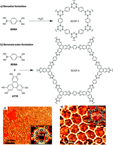 | ||
| Fig. 4 Preparation of SCOF-1 and SCOF-5 under UHV conditions on Ag(111) through (a) boroxine and (b) boronate ester formations. STM images of the (c) SCOF-1 and (d) SCOF-5 networks. The insets show the chemical structures obtained by DFT calculations. Reproduced from ref. 29 with permission from the American Chemical Society, copyright 2008. | ||
Recently, Chen et al. used this approach for the preparation of a single-layer porphyrin-containing COF with a square lattice named COF366-OMe on Au(111).30 In this case, they carried out the Schiff-base condensation reaction between 2,5-dimethoxybenzene-1,4-dicarboxaldehyde (DMA) and 5,10,15,20-tetrakis(4-aminophenyl)porphyrin (TAPP) on a clean Au(111) surface. In the first step, DMA molecules from the vapour phase were adsorbed on the surface with a coverage of 0.9 monolayer (ML) and with a space between molecules of 0.8 nm. Then, TAPP molecules were deposited and the surface was annealed at 150 °C for 1 h under UHV conditions to induce COF formation with a unit cell size of 2.5 nm confirmed by STM images at 7 K (Fig. 5).
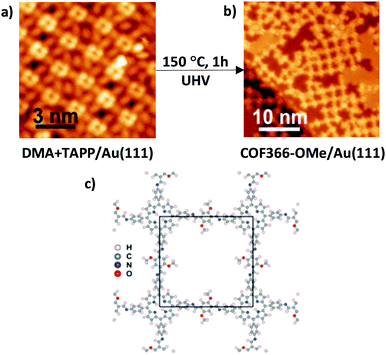 | ||
| Fig. 5 Preparation of COF366-OMe on a Au(111) surface. STM topographic images of (a) a mixture of TAPP and DMA molecules on a Au(111) surface before reaction and (b) COF366-OMe on Au(111) after reaction. (c) Structure of COF366-OMe, with the black square being a unit cell. Reproduced from ref. 30 with permission from the American Chemical Society, copyright 2018. | ||
Another type of polymerization reaction tested under UHV conditions is based on the radical addition of halogenated precursors and subsequent C–C bond formation. In this regard, Lackinger and co-workers prepared covalent phenylene–boroxine networks by the cyclo-condensation of three 3,5-dibromophenylboronic acid (DBPBA) molecules under UHV conditions (Fig. 6).31 The resulting 1,3,5-tris(3,5-dibromophenyl)-boroxine (TDBPB) molecules deposited on an Ag(111) substrate were annealed to produce the more reactive form of triphenylene–boroxine hexaradicals (TPBHR) that polymerized into the final networks through radical addition. It is significant that the preparation of TPBHR was possible due to the presence of bromine groups as well as the catalytic properties of the surface, since the same annealing was carried out using graphite (001) as a substrate without success. STM images revealed the formation of monolayers with short-range order.
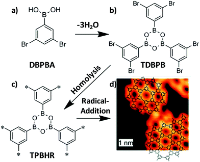 | ||
| Fig. 6 Synthesis of 2D phenylene-boroxine networks from the cyclo-condensation of (a) 3,5-dibromophenylboronic acid (DBPBA) monomers to give rise to (b) 1,3,5-tris(30,50-dibromophenyl)-boroxine (TDBPB). Deposition of TDBPB on Ag(111) and the consequent on-surface homolysis yield (c) surface-stabilized triphenylene–boroxine hexaradicals (TPBHR) which polymerized into covalent phenylene–boroxine networks through radical addition. (d) STM image of the resulting material showing AB stacking in this case. Reproduced from ref. 31 with permission from the Royal Society of Chemistry, copyright 2011. | ||
2.2.1.2 Solid–liquid interface reactions. In contrast to on-surface mediated synthesis under UHV conditions, CONs prepared on substrates under liquid conditions are characterized by the formation of reversible covalent bonds due to the dynamic covalent chemistry.3 Thus, establishing dynamic equilibrium conditions allows the correction of the defects, giving rise to the formation of long-range-ordered surface-supported CONs. However, the main drawback found in the preparation under liquid conditions is the difficulty in controlling the stoichiometry in multicomponent reactions. To create CONs following this preparation method, in the first step, precursors must be dissolved in an organic solvent (alkanes, aliphatic alcohols, or carboxylic acids) and drop-cast on a substrate surface. Then, the polymerization is initiated at room temperature or by a moderated thermal treatment in an open or a closed system.
Following this strategy, Xu et al. achieved almost entire surface coverage (∼1 μm2) after the Schiff-base reaction at room temperature between benzene-1,3,5-tricarbaldehyde and different types of aromatic diamines on a HOPG surface.32 In particular, these authors obtained structures with pore sizes that varied from ∼1.7 to 3.5 nm depending on the length of the amine (Fig. 7).
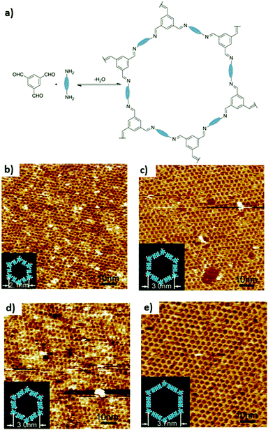 | ||
| Fig. 7 (a) Scheme of the Schiff-base reaction between benzene-1,3,5-tricarbaldehyde and aromatic diamines with different lengths and functionalities. The diamines are symbolically represented by ellipses. Large-scale STM images of COF surfaces prepared with the aromatic diamines: (b) p-phenylenediamine, (c) benzidine, (d) o-tolidine and (e) 4,4′′-diamino-p-terphenyl. The inset in each image shows the chemical structure of a hexagonal pore of every 2D surface COF, respectively. Reproduced from ref. 32 with permission from the American Chemical Society, copyright 2013. | ||
A slight modification of this approach was reported by Liu et al. for the preparation of two imine-based SCOFs on HOPG.33 The strategy followed in this case consisted, first of all, of the preloading by drop-casting of a trigonal precursor onto the substrate. Then, they introduced a second linear precursor and CuSO4·5H2O in the reactor which was closed before heating was started. In particular, in one case they used as monomers tris(4-aminophenyl)benzene (TAPB) and terephthaldicarboxyaldehyde (TPA) to obtain SCOF-IC1, while in the other case they formed SCOF-LZU1 from 1,3,5-triformyl-benzene (TFB) and p-phenylenediamine (PPDA) (Fig. 8). Both honeycomb SCOF structures were corroborated by 2D fast Fourier transform (FFT) of STM images. High resolution STM images showed domain sizes up to 200 × 200 nm2 with some structural defects and lattice parameters of 3.8 and 2.2 nm for SCOF-IC1 and SCOF-LZU1, respectively. These values were confirmed by DFT calculations. Again, the release of water molecules from the dehydration of CuSO4·H2O allows an increase in the reversibility of the aldehyde–amine condensation reaction.
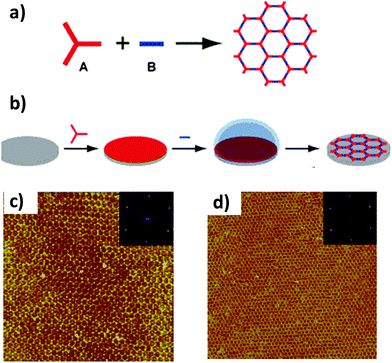 | ||
| Fig. 8 (a) Scheme of the condensation reaction of two precursors A and B to yield the formation of a SCOF. (b) Scheme diagram for a solid–vapour interface reaction. Large-scale STM images (100 × 100 nm2) of (c) SCOF-IC1 and (d) SCOF-LZU1. The insets depict the corresponding FFT spectra of the STM images. Reproduced from ref. 33 with permission from the American Chemical Society, copyright 2013. | ||
It is important to highlight that the experimental parameters used for the on-surface synthesis conditions, such as temperature, pH, concentration and the selection of the substrate and molecular precursors, are decisive in the preparation of well-ordered surface covalent nanostructures. In this sense, Mo et al. achieved polymorphic imine-based surface COFs, namely rhombus, parallelogram and Kagome lattices with modular pore sizes, through careful control of the concentration of precursors with reduced symmetry and using CuSO4·5H2O as a chemical equilibrium regulation agent.34
2.2.2.1 Air/water interface. Synthesis at the air/water interface has great potential for the preparation of single layers, since highly hydrophobic monomers can be confined in a Langmuir monolayer on the interface prior to the reaction. This was already achieved for 2D polymers synthesized through photopolymerization.35 However, the synthesis of COF single layers using this approach proved more challenging. In a first study, the monomers for an imine-linked COF were made to react in a Langmuir trough, forming a free-standing film whose thickness was compatible with that of a single layer.36 Raman spectroscopy showed that imine bond formation took place. Unfortunately, it was not possible to prove if the single layer was ordered or was just an amorphous and disorganized polymer.
Some further advances have been made recently in this area by slightly modifying the approach. The authors did not confine the COF building blocks on the interface, where they can start reacting immediately, before they are preorganized. Instead, a monolayer of a surfactant was generated at the air/water interface. Then, only one of the building blocks was added to the solution. Since the surfactant formed a compact and organized Langmuir layer and was able to interact with the building block, it organized it on the air/water interface (Fig. 9). Finally, addition of the second building block allowed synthesizing a CON through reaction between it and the preorganized layer of the first building block. The resulting film was free-standing and 2 nm thick, roughly corresponding to 5 layers. Most importantly, TEM studies of the films yielded electron diffraction patterns confirming the crystallinity and order of the films.37
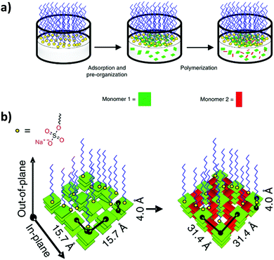 | ||
| Fig. 9 (a) Schematic of the synthetic procedure on the air/water interface assisted by a surfactant layer. (b) Schematic of the preorganization of the first building block followed by CON formation upon addition of the second building block. Reproduced from ref. 37 with permission from Springer Nature, copyright 2019. | ||
2.2.2.2 Liquid/liquid interface. Synthesis at the liquid/liquid interface does not usually afford CON single layers; however, it is a more flexible approach that so far has allowed preparing CONs more easily than synthesis at the air/water interface. The general strategy followed for this type of synthesis consists of confining some of the necessary components for COF formation (building blocks and catalyst) on immiscible solvents, thus restricting the reaction at the liquid/liquid interface. There are reports in which one of the building blocks is in a different phase from the other, as well as examples in which it is the catalyst that is separated from the building blocks.
Dissolving the building blocks in different phases and confining the reaction at the water/dichloromethane interface were found to be possible for the synthesis of keto-enamine CONs.38 Even though COF building blocks are organic molecules that tend to be soluble in organic solvents, the authors took advantage of the basic nature of the amine building block to generate a salt of the protonated amine with p-toluenesulfonic acid, which is soluble in water but not in low polarity solvents. Therefore, when an aqueous solution of the amine salt was layered on top of a solution of the aldehyde in dichloromethane, CON thin films were formed at the interface. The thicknesses of these crystalline films ranged from 50 to 200 nm and could be controlled by tuning the concentration of the building block solutions (the more concentrated the solutions, the thicker the films).
If a reaction like the Suzuki coupling is used to build the COF, it is possible to have both monomers in the same phase, since they will not react in the absence of a suitable catalyst and a base. Thus, synthesis of carbon–carbon bonded CONs was achieved at the water/toluene interface, with both COF building blocks and the palladium catalyst dissolved in the organic phase and the inorganic base confined to the aqueous layer.39 The films obtained were as thin as 18 nm, and their order was corroborated by direct imaging of the structure by TEM, which allowed determining the stacking pattern of the layers.
2.2.2.3 Liquid/liquid/gel triphase system. Another type of confinement can be generated using a hydrogel. If a hydrogel is immersed in an oil (such as tridecane), when drops of water are added to the system, they form a superspreading water layer between the surface of the hydrogel and the oil. By loading one of the building blocks of an imine-linked COF in the hydrogel and dissolving the other in the oil phase, a CON thin film was formed (Fig. 10). The thickness of the films was tuned between 1.8 and 200 nm by varying the concentration of the reactants, and GIXRD measurements showed their crystallinity and that the COF crystallites were oriented with the c-axis of the crystalline structure perpendicular to the surface of the film. Interestingly, the films were free standing and some could be transferred from the surface of the hydrogel to silicon substrates patterned with holes, which allowed measuring their mechanical properties by nanoindentation.40
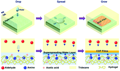 | ||
| Fig. 10 Schematic for the fabrication of thin COF films at hydrogel surfaces based on the confined superspreading water layers under oil. Reproduced from ref. 40 with permission from the American Chemical Society, copyright 2018. | ||
3. Properties and applications
The chemical versatility of COFs enables designing them for multiple applications, including sensing, selective capture of pollutants, energy storage, separations and catalysis.COFs are excellent candidates to be processed as membranes for separation in both liquid and gas phases. This requires COF-membrane fabrication; indeed it is currently accepted that the fabrication of ultrathin (i.e. sub-1 μm-thick) COF membranes is necessary.41 In this context, the use of CONs is central since they can be integrated in mixed matrix membranes (MMMs) or used as nanometer-thick self-standing membranes.
Therefore, the preparation of CONs with a controlled thickness allows the modulation of the properties of the COF material, i.e. making it dispersible in a solvent, which can enhance the performance in some of those applications. Even though bottom-up methods are ideal for the generation of membranes and sometimes afford good control over the orientation and number of layers, most of the CONs tested for applications have been generated by top-down methodologies, due to their easier scalability (Table 1).
| COF | Preparation method | Thickness (nm) | Application | Ref. |
|---|---|---|---|---|
| TPA-COF | Sonication | 3.5 | DNA detection | 17 |
| NUS-2 | Sonication | 50 to 100 | MMMs for CO2 separation | 42 |
| NUS-3 | ||||
| TpBDH | Sonication | ∼1.5 to 5.1 | Sensors | 45 |
| TfpBDH | ||||
| PI-COF | Sonication | 1 | Sensors | 46 |
| COF-1 | Sonication | ∼0.5 | Molecular sieving membranes | 47 |
| ICG@COF-1@PDA | Sonication | 0.7 to 5.4 | Immunogenic phototherapy | 48 |
| Li-CON-TFSI | Chemical exfoliation | 5 | Solid-state lithium batteries | 49 |
| TpTGCl | Chemical exfoliation | 2 to 5 | MMMs for biomedicine | 19 |
| TpTGBr | ||||
| TpTG | ||||
| TpASH | Chemical exfoliation | 15 | Drug delivery | 50 |
| JUC-510 | Chemical exfoliation | 36 | Electrochemical double-layer capacitors | 51 |
| JUC-511 | 22 | |||
| JUC-512 | 19 | |||
| DAAQ-ECOF | Mechanical exfoliation | 5 | Li-ion batteries | 25 |
| Tp-Bpy | Interfacial synthesis | 75 | Nanofiltration | 38 |
| Tp-Azo | 90 | |||
| COFTTA-DHTA | Interfacial synthesis | 4 to 150 | Nanofiltration and sensors | 40 |
| TAPB-PDA COF | Interfacial synthesis | 20 | Nanofiltration | 52 |
An example of the potential of CONs integrated in MMMs is the work of Zhao et al.42 They exfoliated two water stable keto-imine COFs with different pore-sizes and blended the so-formed CONs with two different commercial polymers, already used for gas separation. The resulting MMMs were more permeable to hydrogen but less permeable to carbon dioxide than the membranes made entirely of the selected polymers, thus increasing their performance in H2/CO2 separation.
Another seminal example is the functionalization of α-Al2O3 supports with 3-aminopropyltriethoxysilane and 4-formylphenylboronic acid to prepare the terminal surfaces of boronic acid groups. Subsequently, 1,4-benzenediboronic acid and 2,3,6,7,10,11-hexahydroxytriphenylene underwent a condensation reaction to produce a 1 μm thick COF-5 layer on the α-Al2O3 support under microwave irradiation.43 The main drawback of this approach is that the membranes so-formed are formed by defective COF layers, limiting their application for separation. In this context, Caro et al. recently reported on a continuous preparation of an imine based COF layer, COF-LZU1, with a thickness of 400 nm using α-Al2O3 as a molecular sieving membrane.44
However, although this is a very promising field, it is still in its infancy.41
Interestingly, the downsizing of COFs may affect their physical properties. An example is a recent study in which suspensions of boroxine-linked CONs showed an enhanced quantum yield emission compared to the bulk materials.53 The authors also took advantage of the lower light scattering of the CONs to elucidate the structural factors affecting the fluorescence of these structures, finding evidence of exciplex formation in pyrene containing CONs.
LPE of imine-linked COFs with pyrene building blocks has been used to generate stable suspensions of 3 nm thick CONs in water that retain their fluorescence. These suspensions were shown to be useful for the detection of organic pollutants in water, as the fluorescence of the CONs is quenched in the presence of organic dyes and nitrated aromatic molecules. It is suggested that the aromatic regions of these analytes interact with the pyrene moieties on the surfaces of the CONs, altering the formation of excimers and quenching the fluorescence (Fig. 11).8
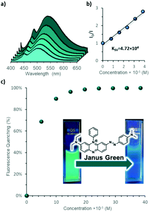 | ||
| Fig. 11 (a) Fluorescence spectra of IMDEA-COF-1 aqueous colloid, showing quenching upon addition of Janus green. (b) Stern–Volmer plot for the quenching of IMDEA-COF-1. (c) Quenching percentage as a function of Janus green concentration. The inset shows vials with IMDEA-COF-1 colloid under UV irradiation before (left) and after (right) Janus green is added. Reproduced from ref. 8 with permission from the Royal Society of Chemistry, copyright 2019. | ||
COFs with redox-active sites have been used as electrodes in lithium-ion batteries.25 However, it was found that even though they are porous and display channels through which the lithium ions can diffuse, this diffusion is too slow and severely hinders their performance, since the lithium ions do not reach the redox sites deep inside the COF crystallites. Thus, the authors of the study used mechanical exfoliation in a ball mill to obtain CONs with redox-active sites. The batteries built with the CONs displayed a better performance. This improvement is related to the shorter diffusion paths in the extremely thin nanolayers, which allows almost all the redox-active sites of the CONs to participate in the electrochemical process.
In a very recent approach, the CO2 capture properties of COFs have been used in the preparation of a catalyst to be tested as a cathode for Li–CO2 batteries. In particular, a nanometer-thin film of an imine-based COF was grown directly on a graphene surface. The polar C![[double bond, length as m-dash]](https://www.rsc.org/images/entities/char_e001.gif) N groups of the COF increased the CO2 adsorption capacities, giving rise to a CO2 nano-enrichment and nanoconfinement which highly improved the efficiency of the LiCO2 battery since the CO2 enhancement reduced the problems of both polarization and cycling.54
N groups of the COF increased the CO2 adsorption capacities, giving rise to a CO2 nano-enrichment and nanoconfinement which highly improved the efficiency of the LiCO2 battery since the CO2 enhancement reduced the problems of both polarization and cycling.54
CON membranes prepared at the liquid/liquid interface have been used for nanofiltration. Since the membrane will need enough mechanical strength to withstand the pressure difference between its two sides during operation, the 40 nm thick CONs were transferred onto thicker polyethersulfone membranes to provide enough support. The resulting membrane with the CON active layer was tested for the rejection of rhodamine WT in aqueous solution in a dead-end filtration cell, showing promising results with a rejection percentage of 91%.52
Membranes can also be prepared from CON suspensions. As an example, boroxine-linked COF-1 was exfoliated by ultrasonication to generate a suspension of CONs in dichloromethane. Then, a zirconia macroporous support was coated with the suspension and allowed to dry. As a result, the CONs assembled and covered the support with a continuous membrane. This membrane showed good permeability for several gases, making it a good candidate for molecular sieving processes.47
COFs have also been employed in biomedical applications such as antitumor therapies thanks to their biocompatible properties. In this regard, CONs were obtained via ultrasonic exfoliation of a bulk COF with near-infrared (NIR) dyes adsorbed onto its surface by π–π interactions. Then, these CONs were stabilized by the addition of a polydopamine (PDA) film and polyethylene glycol (PEG). This innovative 2D material showed relevant results in photodynamic and photothermal therapies due to its NIR dispersion.48
4. Conclusions
The production of different types of 2D materials is providing new potential uses. In particular, the recent production of single- and few-layer COFs has enabled the incorporation of chemically designed materials with precise control of their structures including pores and functionalities that are not feasible for the rest of the 2D-material families (MXenes, transition metal dichalcogenides,…).The implementation of COFs in many applications is limited by their low processability.55 Indeed, preparation of CONs is a suitable way to overcome these limitations and enable their use in some scenarios, as is the case of biomedical applications that require materials with nanometric dimensions or some catalysts that use as active sites the atoms located at the border of the nanolayers. The rational selection and combination of molecular precursors is already providing CONs with a large variety of properties: for instance, photoluminescence, electrode modification, sensing, capture of pollutants, energy storage, (electro)catalysis or separation; therefore, CONs have already been considered as materials for several applications and devices.
Moreover, the recent incorporation of multiple top-down and bottom-up approaches to produce single or few layer CONs in reasonable quantities has allowed fabricating the first proof-of-concept device for several potential applications. As their counterpart bulk materials, one of the most promising applications for CONs is devoted to the fabrication of novel membranes, which enables their use for highly selective and efficient molecular separation and nanofiltration.
Still some potential applications of CONs are hampered by their synthetic methods. Thus, applications in molecular electronics will probably require preparation of single-layer COFs with production methods suitable for a large-scale preparation, such as chemical vapour deposition.
The high social impact that these applications can have in water decontamination and energy consumption is driving significant research efforts in this field. Indeed, this is still a very new research field that has been in development for the last 10 years.
Conflicts of interest
There are no conflicts to declare.Acknowledgements
This work was supported in part by MICINN (grant MAT2016-77608-C3-1-P).Notes and references
- S. Kandambeth, K. Dey and R. Banerjee, J. Am. Chem. Soc., 2019, 141, 1807–1822 CrossRef CAS PubMed
.
- C. S. Diercks and O. M. Yaghi, Science, 2017, 355, eaal1585 CrossRef PubMed
.
- A. P. Côté, A. I. Benin, N. W. Ockwig, M. O’Keeffe, A. J. Matzger and O. M. Yaghi, Science, 2005, 310, 1166–1170 CrossRef PubMed
.
- J. L. Segura, M. J. Mancheño and F. Zamora, Chem. Soc. Rev., 2016, 45, 5635–5671 RSC
.
- H. Fan, A. Mundstock, A. Feldhoff, A. Knebel, J. Gu, H. Meng and J. Caro, J. Am. Chem. Soc., 2018, 140, 10094–10098 CrossRef CAS PubMed
.
- M. Calik, F. Auras, L. M. Salonen, K. Bader, I. Grill, M. Handloser, D. D. Medina, M. Dogru, F. Löbermann, D. Trauner, A. Hartschuh and T. Bein, J. Am. Chem. Soc., 2014, 136, 17802–17807 CrossRef CAS PubMed
.
- H. Xu, J. Gao and D. Jiang, Nat. Chem., 2015, 7, 905–912 CrossRef CAS PubMed
.
- P. Albacete, A. López-Moreno, S. Mena-Hernando, A. E. Platero-Prats, E. M. Pérez and F. Zamora, Chem. Commun., 2019, 55, 1382–1385 RSC
.
- B. Sun, C.-H. Zhu, Y. Liu, C. Wang, L.-J. Wan and D. Wang, Chem. Mater., 2017, 29, 4367–4374 CrossRef CAS
.
- R. Mas-Ballesté, C. Gómez-Navarro, J. Gómez-Herrero and F. Zamora, Nanoscale, 2011, 3, 20–30 RSC
.
- V. Nicolosi, M. Chhowalla, M. G. Kanatzidis, M. S. Strano and J. N. Coleman, Science, 2013, 340, 1226419 CrossRef
.
- J. Sakamoto, J. van Heijst, O. Lukin and A. D. Schlüter, Angew. Chem., Int. Ed., 2009, 48, 1030–1069 CrossRef CAS PubMed
.
- J. Dong, Z. Qiao, Y. Pan, S. B. Peh, Y. Di Yuan, Y. Wang, L. Zhai, H. Yuan, Y. Cheng, H. Liang, B. Liu and D. Zhao, Chem. Mater., 2019, 31, 4897–4912 CrossRef CAS
.
- J. Dong, K. Zhang, X. Li, Y. Qian, H. Zhu, D. Yuan, Q.-H. Xu, J. Jiang and D. Zhao, Nat. Commun., 2017, 8, 1142 CrossRef PubMed
.
- I. Berlanga, M. L. Ruiz-González, J. M. González-Calbet, J. L. G. Fierro, R. Mas-Ballesté and F. Zamora, Small, 2011, 7, 1207–1211 CrossRef CAS PubMed
.
- I. Berlanga, R. Mas-Ballesté and F. Zamora, Chem. Commun., 2012, 48, 7976 RSC
.
- Y. Peng, Y. Huang, Y. Zhu, B. Chen, L. Wang, Z. Lai, Z. Zhang, M. Zhao, C. Tan, N. Yang, F. Shao, Y. Han and H. Zhang, J. Am. Chem. Soc., 2017, 139, 8698–8704 CrossRef CAS PubMed
.
- M. A. Khayum, S. Kandambeth, S. Mitra, S. B. Nair, A. Das, S. S. Nagane, R. Mukherjee and R. Banerjee, Angew. Chem., Int. Ed., 2016, 55, 15604–15608 CrossRef CAS PubMed
.
- S. Mitra, S. Kandambeth, B. P. Biswal, A. M. Khayum, C. K. Choudhury, M. Mehta, G. Kaur, S. Banerjee, A. Prabhune, S. Verma, S. Roy, U. K. Kharul and R. Banerjee, J. Am. Chem. Soc., 2016, 138, 2823–2828 CrossRef CAS PubMed
.
- K. S. Novoselov, D. Jiang, F. Schedin, T. J. Booth, V. V. Khotkevich, S. V. Morozov and A. K. Geim, Proc. Natl. Acad. Sci. U. S. A., 2005, 102, 10451 LP–10453 LP CrossRef PubMed
.
- S. Z. Butler, S. M. Hollen, L. Cao, Y. Cui, J. A. Gupta, H. R. Gutiérrez, T. F. Heinz, S. S. Hong, J. Huang, A. F. Ismach, E. Johnston-Halperin, M. Kuno, V. V. Plashnitsa, R. D. Robinson, R. S. Ruoff, S. Salahuddin, J. Shan, L. Shi, M. G. Spencer, M. Terrones, W. Windl and J. E. Goldberger, ACS Nano, 2013, 7, 2898–2926 CrossRef CAS PubMed
.
- A. Abhervé, S. Mañas-Valero, M. Clemente-León and E. Coronado, Chem. Sci., 2015, 6, 4665–4673 RSC
.
- B. P. Biswal, S. Chandra, S. Kandambeth, B. Lukose, T. Heine and R. Banerjee, J. Am. Chem. Soc., 2013, 135, 5328–5331 CrossRef CAS PubMed
.
- S. Chandra, S. Kandambeth, B. P. Biswal, B. Lukose, S. M. Kunjir, M. Chaudhary, R. Babarao, T. Heine and R. Banerjee, J. Am. Chem. Soc., 2013, 135, 17853–17861 CrossRef CAS PubMed
.
- S. Wang, Q. Wang, P. Shao, Y. Han, X. Gao, L. Ma, S. Yuan, X. Ma, J. Zhou, X. Feng and B. Wang, J. Am. Chem. Soc., 2017, 139, 4258–4261 CrossRef CAS PubMed
.
- J. V. Barth, G. Costantini and K. Kern, Nature, 2005, 437, 671–679 CrossRef CAS PubMed
.
- P. Samorì, Chem. Soc. Rev., 2005, 34, 551–561 RSC
.
- F. Cacialli, P. Samorì and C. Silva, Mater. Today, 2004, 7, 24–32 CrossRef CAS
.
- N. A. A. Zwaneveld, R. Pawlak, M. Abel, D. Catalin, D. Gigmes, D. Bertin and L. Porte, J. Am. Chem. Soc., 2008, 130, 6678–6679 CrossRef CAS PubMed
.
- C. Chen, T. Joshi, H. Li, A. D. Chavez, Z. Pedramrazi, P.-N. Liu, H. Li, W. R. Dichtel, J.-L. Bredas and M. F. Crommie, ACS Nano, 2018, 12, 385–391 CrossRef CAS PubMed
.
- S. Schlögl, T. Sirtl, J. Eichhorn, W. M. Heckl and M. Lackinger, Chem. Commun., 2011, 47, 12355 RSC
.
- L. Xu, X. Zhou, Y. Yu, W. Q. Tian, J. Ma and S. Lei, ACS Nano, 2013, 7, 8066–8073 CrossRef CAS PubMed
.
- X.-H. Liu, C.-Z. Guan, S.-Y. Ding, W. Wang, H.-J. Yan, D. Wang and L.-J. Wan, J. Am. Chem. Soc., 2013, 135, 10470–10474 CrossRef CAS PubMed
.
- Y.-P. Mo, X.-H. Liu and D. Wang, ACS Nano, 2017, 11, 11694–11700 CrossRef CAS PubMed
.
- D. J. Murray, D. D. Patterson, P. Payamyar, R. Bhola, W. Song, M. Lackinger, A. D. Schlüter and B. T. King, J. Am. Chem. Soc., 2015, 137, 3450–3453 CrossRef CAS PubMed
.
- W. Dai, F. Shao, J. Szczerbiński, R. McCaffrey, R. Zenobi, Y. Jin, A. D. Schlüter and W. Zhang, Angew. Chem., Int. Ed., 2016, 55, 213–217 CrossRef CAS PubMed
.
- K. Liu, H. Qi, R. Dong, R. Shivhare, M. Addicoat, T. Zhang, H. Sahabudeen, T. Heine, S. Mannsfeld, U. Kaiser, Z. Zheng and X. Feng, Nat. Chem., 2019, 11, 994–1000 CrossRef CAS PubMed
.
- K. Dey, M. Pal, K. C. Rout, S. H. Kunjattu, A. Das, R. Mukherjee, U. K. Kharul and R. Banerjee, J. Am. Chem. Soc., 2017, 139, 13083–13091 CrossRef CAS PubMed
.
- D. Zhou, X. Tan, H. Wu, L. Tian and M. Li, Angew. Chem., Int. Ed., 2019, 58, 1376–1381 CrossRef CAS PubMed
.
- Q. Hao, C. Zhao, B. Sun, C. Lu, J. Liu, M. Liu, L.-J. Wan and D. Wang, J. Am. Chem. Soc., 2018, 140, 12152–12158 CrossRef CAS PubMed
.
- C. Zhang, B.-H. Wu, M.-Q. Ma, Z. Wang and Z.-K. Xu, Chem. Soc. Rev., 2019, 48, 3811–3841 RSC
.
- Z. Kang, Y. Peng, Y. Qian, D. Yuan, M. A. Addicoat, T. Heine, Z. Hu, L. Tee, Z. Guo and D. Zhao, Chem. Mater., 2016, 28, 1277–1285 CrossRef CAS
.
- D. Hao, J. Zhang, H. Lu, W. Leng, R. Ge, X. Dai and Y. Gao, Chem. Commun., 2014, 50, 1462–1464 RSC
.
- H. Fan, J. Gu, H. Meng, A. Knebel and J. Caro, Angew. Chem., Int. Ed., 2018, 57, 4083–4087 CrossRef CAS PubMed
.
- G. Das, B. P. Biswal, S. Kandambeth, V. Venkatesh, G. Kaur, M. Addicoat, T. Heine, S. Verma and R. Banerjee, Chem. Sci., 2015, 6, 3931–3939 RSC
.
- C. Zhang, S. Zhang, Y. Yan, F. Xia, A. Huang and Y. Xian, ACS Appl. Mater. Interfaces, 2017, 9, 13415–13421 CrossRef CAS PubMed
.
- G. Li, K. Zhang and T. Tsuru, ACS Appl. Mater. Interfaces, 2017, 9, 8433–8436 CrossRef CAS PubMed
.
- S. Gan, X. Tong, Y. Zhang, J. Wu, Y. Hu and A. Yuan, Adv. Funct. Mater., 2019, 29, 1902757 CrossRef CAS
.
- H. Chen, H. Tu, C. Hu, Y. Liu, D. Dong, Y. Sun, Y. Dai, S. Wang, H. Qian, Z. Lin and L. Chen, J. Am. Chem. Soc., 2018, 140, 896–899 CrossRef CAS PubMed
.
- S. Mitra, H. S. Sasmal, T. Kundu, S. Kandambeth, K. Illath, D. Díaz Díaz and R. Banerjee, J. Am. Chem. Soc., 2017, 139, 4513–4520 CrossRef CAS PubMed
.
- Y. Yusran, H. Li, X. Guan, D. Li, L. Tang, M. Xue, Z. Zhuang, Y. Yan, V. Valtchev, S. Qiu and Q. Fang, Adv. Mater., 2020, 32, 1907289 CrossRef CAS PubMed
.
- M. Matsumoto, L. Valentino, G. M. Stiehl, H. B. Balch, A. R. Corcos, F. Wang, D. C. Ralph, B. J. Mariñas and W. R. Dichtel, Chem, 2018, 4, 308–317 CAS
.
- A. M. Evans, I. Castano, A. Brumberg, L. R. Parent, A. R. Corcos, R. L. Li, N. C. Flanders, D. J. Gosztola, N. C. Gianneschi, R. D. Schaller and W. R. Dichtel, J. Am. Chem. Soc., 2019, 141, 19728–19735 CrossRef CAS PubMed
.
- S. Huang, D. Chen, C. Meng, S. Wang, S. Ren, D. Han, M. Xiao, L. Sun and Y. Meng, Small, 2019, 15, 1904830 CrossRef CAS PubMed
.
- D. Rodríguez-San-Miguel and F. Zamora, Chem. Soc. Rev., 2019, 48, 4375–4386 RSC
.
| This journal is © The Royal Society of Chemistry 2020 |


