Supramolecular design in 2D covalent organic frameworks
Sampath B.
Alahakoon
,
Shashini D.
Diwakara
,
Christina M.
Thompson
and
Ronald A.
Smaldone
 *
*
Department of Chemistry and Biochemistry, University of Texas, Dallas, 800 W. Campbell Rd, Richardson, TX 75080, USA. E-mail: ronald.smaldone@utdallas.edu
First published on 19th February 2020
Abstract
2D covalent organic frameworks (COFs) are a class of porous polymers with highly crystalline structures and tunable function. The structure of a 2D-COF consists of two dimensional sheets held together through covalent bonds which are then stacked together through non-covalent forces. Since their first report, the synthesis of new COFs has relied mostly on imparting functionality to the monomer structures through covalent modification, or through the use of new thermodynamically controlled covalent bond forming methods. This tutorial review will discuss recent efforts to use supramolecular design to leverage the non-covalent forces between COF monomers and sheets to improve their properties and function. The importance of supramolecular interactions in COFs to their mechanisms of formation and overall structure will also be covered.
Key learning points1. 2D covalent organic frameworks (COFs) rely heavily on non-covalent interactions to hold their 2D sheets together.2. One method to increase fidelity between the layers is to increase the amount of π-surface in the linker monomers. Alternatively, smaller aromatic units can be used if they are electronically tuned to increase the co-facial interaction strength between monomers. 3. Increased monomer planarity does in fact lead to more highly ordered COFs, however, designed non-planarity that leads to monomers on adjacent sheets ‘locking’ together has also been shown to be effective, even with extremely twisted shapes. 4. Hydrogen bonding can also stabilize interlayer adhesion and increase the crystallinity and surface area of COFs, but requires that they are correctly oriented between layers. 5. The next frontier in COF design may be to take inspiration from supramolecular chemistry to improve the properties and open up new applications for these versatile materials. |
Introduction
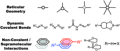
2D covalent organic frameworks1–5 (2D-COFs) are a class of polymers that are comprised of organic monomers linked in two dimensions through covalent bonds that then stack on one another in an ordered fashion through non-covalent interactions. COFs are defined as permanently porous and have high crystallinity, properties which are characterized through nitrogen adsorption and powder X-ray diffraction (PXRD). Unlike 3D-COFs where the growth and crystallinity of the structure is determined by covalent bond formation alone, the nature and magnitude of the non-covalent interactions can have profound implications on the crystallinity (or lack thereof in some cases) and function of the COF. Non-covalent interactions play a critical role in the formation of 2D-COFs as well as influencing the bulk properties of the resultant materials, including surface area, conductivity,16–19 capacitance,20,21 and luminescence.22–27Since the first COF was reported by Yaghi and coworkers in 2005,1 researchers have made tremendous efforts to make use of new dynamic covalent reactions and control aromatic interactions between monomers to improve the bulk properties of 2D-COFs. Traditionally, the design parameters for a 2D-COF have been similar to those of other reticular materials such as metal organic frameworks (MOFs).28,29 A rigid, and often symmetrical, monomer is fitted with functional groups capable of participating in dynamic covalent reactions such as imine condensation, or boronate ester metathesis. The pore shape and size are determined by the geometry of the monomer unit and, in many cases, complementary co-monomers. In previous years, the development of new COFs revolved around the addition of sidechain functional groups to the monomer units to impart new capabilities onto the COF, or the development of new dynamic bond forming reactions compatible with the polymerization of COF materials (Fig. 1).
While these are still active and important approaches to COF development, only recently have researchers attempted to better understand how non-covalent interactions control the adhesion of the 2D layers, and how these forces affect the mechanism of COF polymerization. As 2D-COFs can generally be described as covalently linked sheets stacked together through non-covalent interactions, the choice of supramolecular interaction should work in concert with this basic structural arrangement. Interactions between layers requires proper orientation so that the directionality of the supramolecular bonds are accounted for.
The fidelity of these interlayer interactions is absolutely critical to bulk properties such as electrical conductivity, pore size control, and even their hydrolytic stability. This tutorial review will cover research on the importance and design considerations for a variety of non-covalent interlayer interactions in 2D-COFs including van der Waals, aromatic stacking, and hydrogen bonding interactions.
Dipolar, van der Waals and aromatic stacking interactions
In most 2D-COFs, the sheets obtained through polymerization are stacked via non-covalent interactions such as aromatic stacking interactions and van der Waals/dipolar forces. In this part of the review, we will discuss the effect of aromatic interactions on the bulk properties of the 2D-COF materials. Aromatic interactions typically result in slightly offset face-to-face packing in order to minimize the repulsion between π-clouds of each ring. As such, the magnitude of the stacking interaction is dependent on a number of factors, including the functional groups attached to the periphery of the ring. Electron deficient rings that stack with one another can result in relatively strong stacking interactions,30 as can a mixture of electron rich and electron poor rings when they adopt alternating stacks with similar offset packing interactions.31–34 Each of these concepts has been used in the construction of COFs and will be discussed in this section.One of the earliest, in depth analyses of the nature of COF crystallization involved the computational study of boronate ester COFs (Fig. 2).10 The arrangement of the 2D-COF layers was examined through a simulation in which the layers were moved in small increments to generate a potential energy surface (PES). These experiments found that the minimum energy regions of the PES corresponded to sheet arrangements that were slightly offset from eclipsed with the electron rich oxygen atoms of the boronate ester groups situated directly over the electron poor boron atoms of the adjacent COF sheet. The eclipsed configuration is more favorable owing to the interlayer alignment of the electron poor boron atoms of one layer and the electron rich oxygen atoms of the adjacent layer. This work provided significant insight into the importance of interlayer interactions in the assembly of COFs from a mechanistic perspective.
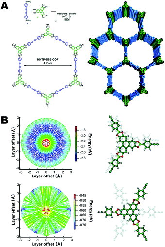 | ||
| Fig. 2 (A) Large pore, boronate ester linked COF. (B) Potential energy surface of the hexahydroxytriphenylene boronate ester unit in both the eclipsed and staggered configurations. Reproduced from ref. 10 with permission from ACS Publications, copyright 2011. | ||
Though the dipolar B–O interactions in boronate ester COFs are important, further studies by Smith et al. demonstrated that the size of the aromatic surface in the linker was also critical (Fig. 3).35 In order to study the rate and mechanism of COF formation, Smith et al. carried out the synthesis of a series of boronate ester COFs using a homogeneous solution of monomers. The relative rates of COF formation were obtained through turbidity measurements. Once the polymerization began, there was a short lag period before the COFs would precipitate from solution resulting in increased opacity in the solution. From these experiments, the authors found that the size of the aromatic monomers could be correlated to the rate of COF formation. Furthermore, the ability of the COF to resist hydrolytic degradation was also improved with the larger aromatic monomers, indicating that the interlayer interactions not only improved the polymerization rate, but also could have a profound effect on bulk properties such as surface area, pore fidelity and overall stability.
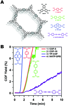 | ||
| Fig. 3 (A) A series of boronate ester COFs with varying π-surface sizes. (B) Rates of COF formation observed through turbidity measurements. Figure adapted from ref. 35 with permission from the Royal Society of Chemistry, copyright 2015. | ||
While the above work shows a clear increase in rate of COF formation with increased π surface area, the boronate ester COF used in that study is known to form slip-stack motifs, as the favourable dipole interactions between the boron and the adjacent oxygen synergize with the well-known lower energy arrangement of aromatic rings in slip-stacks.30,34 In 2013, Jiang and co-workers7 created a design to improve the crystallinity and surface area of 2D-COFs by exploiting charge transfer interactions between electron rich and electron poor rings in imine COFs. In this work, 2,3,5,6-tetrafluoroterephthalaldehyde (TFTA) and terephthalaldehyde (TA) were used as the electron-deficient and the electron-rich components, respectively, in the COF synthesis. The aldehydes TFTA and TA were mixed in five different molar ratios (100/0, 75/25, 50/50, 25/75 and 0/100) and separately reacted with a copper porphyrin monomer (5,10,15,20-tetrakis(p-tetraphenylamino) porphyrin, CuP) to yield five different COFs under solvothermal conditions (Fig. 4). This series of COFs were activated and characterized using powder X-ray diffraction (PXRD) and surface area analysis. Within this COF series, the CuP-TFPh50 COF which contains a 50![[thin space (1/6-em)]](https://www.rsc.org/images/entities/char_2009.gif) :
:![[thin space (1/6-em)]](https://www.rsc.org/images/entities/char_2009.gif) 50 ratio of TFTA/TA, had the highest intensity of the 100 reflection (30
50 ratio of TFTA/TA, had the highest intensity of the 100 reflection (30![[thin space (1/6-em)]](https://www.rsc.org/images/entities/char_2009.gif) 300 cps) compared with all other feed ratios, indicating a higher level of crystallinity (Fig. 5A). The BET surface areas also demonstrated a similar trend with the highest surface area observed for CuP-TFPh50 (1389 m2 g−1) (Fig. 5B and C).
300 cps) compared with all other feed ratios, indicating a higher level of crystallinity (Fig. 5A). The BET surface areas also demonstrated a similar trend with the highest surface area observed for CuP-TFPh50 (1389 m2 g−1) (Fig. 5B and C).
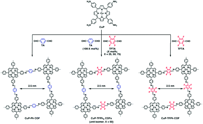 | ||
Fig. 4 COFs synthesized containing aromatic linkers of different electron densities. Variation of the monomer feed ratio can strongly affect the COF crystallinity and surface area. In this case, a 1![[thin space (1/6-em)]](https://www.rsc.org/images/entities/char_2009.gif) : :![[thin space (1/6-em)]](https://www.rsc.org/images/entities/char_2009.gif) 1 ratio of TA and TFTA results in the most crystalline structure because of the interlayer interactions between electron rich and poor rings. Reproduced from ref. 7 with permission from ACS Publications, copyright 2013. 1 ratio of TA and TFTA results in the most crystalline structure because of the interlayer interactions between electron rich and poor rings. Reproduced from ref. 7 with permission from ACS Publications, copyright 2013. | ||
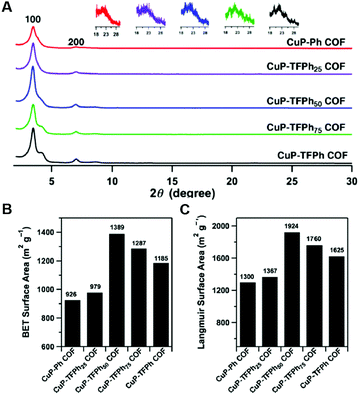 | ||
| Fig. 5 (A) PXRD spectra of COFs. Insets: Enlarged 001 facets. (B) BET and (C) Langmuir surface areas. Reproduced from ref. 7 with permission from ACS Publications, copyright 2013. | ||
Interestingly, the authors observed a smaller interlayer distance value for CuP-TFPh50 COF (3.85 Å) compared to CuP-Ph (3.97 Å) and CuP-TFPh (3.98 Å) COFs with 100% TA and TFTA, respectively. The other lattice parameters were also shorter (25.2 Å) compared to CuP-Ph and CuP-TFPh COFs (25.4 Å). Those observations were attributed to strong charge transfer interactions in the CuP-TFPh50 COF compared the COFs with other feed ratios of the fluorinated and non-fluorinated TA monomers. For a further quantitative understanding of the stacking interactions between layers, computational calculations were performed using the density functional tight-binding (DFTB) method with a Lennard-Jones (LJ) dispersion. According to the stacking energies obtained, anti-CuP-TFPh50 and syn-CuP-TFPh50 had higher interaction energies compared to the CuP-Ph and CuP-TFPh COFs. Between the anti- and syn-isomers, the anti-isomer with a 0.9 Å slipped AA stacking structure showed the largest stacking energy (68.11 kcal mol−1). Further, the CuP-TFPh50 displayed greater electron transfer capability, bearing a very low HOMO–LUMO gap of 0.05 eV compared with the gaps for CuPh and CuP-TFPh of 0.131 eV and 0.065 eV, respectively.
In 2018, Johnson and co-workers reported a similar strategy to improve the bulk crystallinity of an imine COF.36 In this report, the aromatic donor–acceptor complex formation was implemented using perfluorinated aldehydes and amine monomers with their counter non-fluorinated monomers in the vertices of the COF crystal. To more clearly understand the effect, a series of COFs were synthesized including the control COF which does not contain fluorine (Fig. 6).
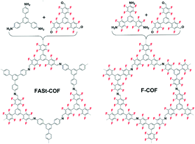 | ||
| Fig. 6 Fluorine containing COFs made through imine metathesis reactions. By using different monomer feed ratios of fluorinated and non-fluorinated monomers, the crystallinity and surface area can be improved. Reproduced from ref. 36 with permission from ACS Publications, copyright 2018. | ||
The activated COFs were characterized through N2 sorption measurements and PXRD analysis. The surface area for the Base-COF was measured as 970 m2 g−1 and was the lowest in the series and FASt-COF had the highest surface area 1700 m2 g−1 (Fig. 7A). Interestingly, the 001 reflection of the PXRD of the FASt-COF is easily visible in the diffraction pattern as opposed to the other COFs in the series (Fig. 7B). This reflection corresponds to the interlayer sheet stacking, attributed to π–π stacking in this case. In the transmission electron microscopy (TEM) images rod- or tube-like crystallites were seen for FASt-COF which were not observed for the other COFs in the series. These crystallite morphologies are typically correlated with high crystallinity in COFs, in this case induced by the fluorine groups in FASt-COF. To help explain the electronic effects induced by the fluorine atoms, the authors carried out van der Waals corrected DFT calculations. The calculated cohesive energy for the alternating structure was 28.2 kJ mol−1 higher than the non-alternating structure and the interlayer distances were 3.51 Å and 3.62 Å respectively. The experimental observations and the theoretical calculations suggest that there is a significant stabilization owing to donor–acceptor interactions in the alternating structure of the FASt-COF compared to the other COFs in the series.
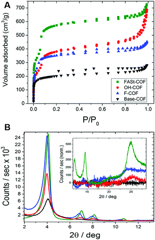 | ||
| Fig. 7 (A) BET isotherms of each COF. (B) PXRD patterns of the synthesized COFs. Inset: Enlarged 001 reflections. Reproduced from ref. 36 with permission from ACS Publications, copyright 2018. | ||
While highly fluorinated monomers can be used to induce charge transfer interactions, monomers with lower degrees of substitution can also be used to modify the electronic structure of COFs in more subtle ways. Our group developed a monomer design to control the π-cloud polarization through electron-withdrawing (EW) fluorine substituents.11 We hypothesized that this design could bias the formation of eclipsed COF layers as the electron-deficient rings are known to preferentially adopt face–face arrangements. Here fluorine was used as the EW substituent which is similar in steric bulk of hydrogen. Two fluorine containing COFs (TF-COF 1 and TF-COF 2) were synthesized and the bulk properties were compared with their non-fluorinated analogue (NF-COF) (Fig. 8). Interestingly, we observed a remarkable improvement in the crystallinity, surface area and the pore fidelity of the resulting fluorinated COFs compared to their non-fluorinated analogues. TF-COF1 and 2 displayed type IV isotherms with BET surface areas of 1820 and 2044 m2 g−1 respectively compared to NF-COF with 760 m2 g−1 and a type I isotherm (Fig. 9A).
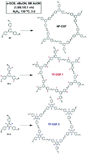 | ||
| Fig. 8 Schematic representation of the synthesis of NF-COF, TF-COF 1 and 2. Reproduced from ref. 11 with permission from Wiley-VCH Verlag GmbH & Co., copyright 2017. | ||
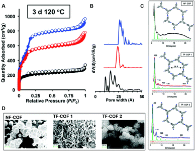 | ||
| Fig. 9 (A) BET isotherms, (B) pore size distributions, (C) PXRDs (inset: modeled structures of COFs), of NF-COF (black), TF-COF 1 (red) and TF-COF 2 (blue). (D) SEM images of COFs. Reproduced from ref. 11 with permission from Wiley-VCH Verlag GmbH & Co., copyright 2017. | ||
Both TF-COFs showed narrow pore-size distributions (∼25 Å) which were in good agreement with the modelled structures (Fig. 9B and C). In the PXRD patterns, well resolved peaks with high intensity were observed for both the fluorinated COFs compared to NF-COF (Fig. 9C). As observed under SEM, the fluorinated COFs adopted a rod-shaped morphology compared to spherical shaped morphology in the NF-COF (Fig. 9D). These observations can be attributed to the effect of EW groups (fluorine) in π-cloud polarization of the aromatic rings which could lead to stronger aromatic interactions. Also, the change in electronic structure could favor the formation of thermodynamically favorable crystalline product over amorphous kinetic product.
A follow up experimental and computational study was performed to further elucidate the effect of fluorine in the advancement of the materials quality of 2D-COFs.6 Here a series of mixed COFs (TFx-COFs) were synthesized using fluorinated and non-fluorinated monomers with varying feed ratios (x) (Fig. 10A). Out of the series TF75 and TF100-COFs showed multiple observable diffraction peaks in the PXRD with higher intensity, and TF100-COF showed the greatest resolution of peaks with the highest intensity. Poor crystallinity was observed in TF0-COF and TF25-COF (Fig. 10C). The BET surface areas of the COFs increases incrementally as x varies from 25–75, however, TF100-COF showed a surface area of 1802 m2 g−1 which is a significant improvement (756 m2 g−1) compared to TF75-COF (Fig. 10B). Apart from that, the microscopic morphology of the crystallites of the series of COFs showed a variation from spherical agglomerates to rods when x varies from 0–100. This is attributed to improved COF growth in the z-axis owing to the preference for co-facial interactions between rings. This was rationalized by the increased π-cloud polarization induced by fluorine substitutions in the aromatic rings.30 To help explain this further, quantum mechanical calculations were performed to determine the relative interaction energies between each monomer type. The calculations revealed that there is a stronger preference for co-facial arrangement in TF–TF compared to NF–NF and NF–TF assemblies, with TF–TF having a greater stabilization energy of 32 kJ mol−1 compared to NF–NF arrangement. These results help explain the driving force for the self-assembly of electron deficient aromatic monomers to yield the COFs (TF100-COF) with higher crystallinity and surface area. Hence, this design reveals a new strategy of making crystalline COFs with improved bulk properties using homogenous mixtures of electron deficient monomers.
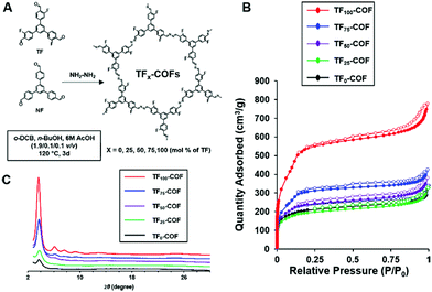 | ||
| Fig. 10 (A) Synthesis scheme (B) BET isotherms and (C) PXRDs of mixed-linker TF-COFs. Reproduced from ref. 6 with permission from the Royal Society of Chemistry, copyright 2017. | ||
Salonen and co-workers reported a unique approach to interlayer COF stabilization by synthesizing a pyrene dione unit that stacks in an alternating fashion which results in the cancellation of the monomer dipole moments resulting in a highly crystalline COF (Fig. 11A).12 These boronate ester COFs have high surface areas and pore fidelity. Quantum mechanical calculations indicated that the antiparallel arrangement (Fig. 11B) of the pyrene dione stacking was favorable by more than 7 kcal mol−1 in comparison with the unfunctionalized pyrene unit, and 5.5 kcal mol−1 more than the parallel arrangement of the pyrene dione (Fig. 11C). This work demonstrates another potential approach for using a single set of monomers that will result in self-complementary stabilization between layers.
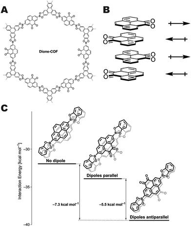 | ||
| Fig. 11 (A) Structure of dione-COF, (B) schematic of the dipole canceling arrangement of the monomers, and (C) relative interaction energies of the dione-COF linkers in both the parallel and antiparallel arrangement in comparison with the native pyrene monomer. Reproduced from ref. 12 with permission from the Royal Society of Chemistry, copyright 2016. | ||
The importance of COF monomer topography
Another design element that has been shown to strongly impact the overall crystallinity of a COF system is the shape of the building blocks themselves. Planar molecules stack together more closely, allowing other important interactions like π stacking, hydrogen bonding, and dipole–dipole interactions to take place.One example of improved monomer planarity leading to higher surface area and crystallinity in COFs was reported by Lotsch and co-workers.37 In their work to produce photocatalytic COFs, they replaced the triphenylbenzene based monomer previously used to produce COF-4338 with a triazine derivative. This substitution removes the steric hindrance between the C–H bonds of the central phenyl ring and the substituent phenyl rings, allowing for smaller torsion angles between all of the rings. This substitution produced a COF with a BET surface area of 1600 m2 g−1, which was not only the highest surface area for a hydrazone COF at the time, but twice the surface area of COF-43, its close structural analog. They calculated that substituting the triazine planarized the dihedral angle between the phenyl rings and the triazine unit from around 38° to 7.7°, which resulted in improved co-facial stacking interactions and the subsequent bulk crystallinity of the COF.
Banerjee and co-workers applied this same concept to two new imine COFs, 2,3-DhaTta, which contains a triazine core, and 2,3-DhaTab which contains a triaminotriphenylbenzene core (Fig. 12).15 These triamines were then polymerized with terethphalaldehyde decorated with diols. The diols make hydrogen bonds with the imines created when the two-dimensional polymer sheets form, further planarizing them. They found the more planar 2,3-DhaTta had a surface area of 1700 m2 g−1, whereas the less planar 2,3-DhaTab had a measured surface area of only 413 m2 g−1. When the PXRD of the 2,3-Dha-Tta was compared to that of 2,3-DhaTab after 12 hours of reaction time they found that the ratio of the 100 to the 001 reflections was nine times larger for the triazine containing COF, indicating much more favourable stacking in the z axis for the planarized COF. More interestingly, they saw a change in the overall morphology of the COF solids. The triazine containing COFs formed ribbon-like structures, which they hypothesize is because the higher planarity favours improved growth in the stacking direction. The non-planar 2,3-DhaTab COF instead formed hollow spheres through an inside-out Ostwald ripening mechanism. This comparison is an excellent example of the macroscale affects that planarity can have on overall COF properties.
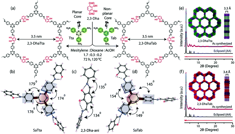 | ||
| Fig. 12 (a) Structures of 2,3-DhaTta and 2,3-DhaTab. Dihedral angles of the SaTta (b), 2,3-DhaTta (c) and SaTab (d) units. (e) and (f) Simulated and experimental PXRD patterns of the eclipsed 2,3-DhaTta and 2,3-Dha Tab COFs, respectively. Reproduced from ref. 15 with permission from Wiley-VCH Verlag GmbH & Co., copyright 2016. | ||
While many non-planar building blocks have been shown to reduce overall crystallinity,37,39,40 others have shown the opposite trend. Recently, a new design paradigm has emerged resulting in very highly crystalline COFs containing decidedly non-planar molecules that can dock into each other.41,42 Inspired by how propeller shaped objects lock securely into each other, Bein and co-workers designed a COF using a tetraphenylethylene core,43 a decidedly out-of-plane propeller shaped monomer. Using this monomer, they were able to produce COFs with surface areas ranging from 2140 m2 g−1 to 1000 m2 g−1. Their tetraphenylethylene core has a drawback, in that it can form a “left” or “right-handed” configuration. These two configurations don’t crystalize together perfectly, leading to imperfections in the crystal lattice. They attributed the large range in the obtained surface areas to the bringing ligands’ ability to translate the direction of rotation from one stack of tetraphenylene to its neighbours. Monomers that contained an internal C2 axis did a better job of lining up with adjacent stacks of tetraphenylethylene monomers than linkers without a C2 axis, thus leading to higher surface areas.
The authors followed up with another example using 1,3,6,8-tetrakis(4-aminophenyl)pyrene cores (Fig. 13).41 The four phenyl rings surrounding the pyrene core can rotate to adopt several conformations, one being a propeller shape in which the normal vectors of the phenyl rings describe a circle, and another as an arm-chair configuration, in which all the normal vectors of the phenyl rings point in the same direction. Calculations carried out on model compounds indicated that the propeller shape was unlikely to stack together closely enough to form a stable COF, but that the armchair configuration would have small stack offsets and close enough interlayer interactions for stable COF formation. While in the solid state, only the ‘propeller” shape had been reported, the authors hypothesized that they might be able to form a stable COF if they could cause the phenyl rings to adapt an armchair configuration using correct linker selection. In this they were successful, finding that small or flat linkers were able to communicate the orientation of the phenylenes of one pyrene unit to its neighbours, allowing for better long-range order and therefore crystallinity.
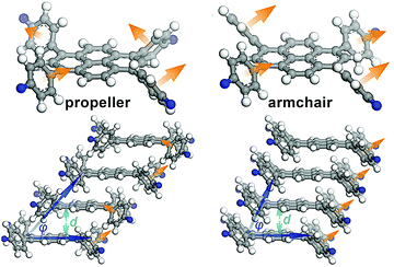 | ||
| Fig. 13 Out of plane torsions of an imine COF containing 1,3,6,8-tetrakis(4-aminophenyl)pyrene units. Reproduced from ref. 33 with permission from ACS Publications, copyright 2016. | ||
In our own work14 we have shown that fluoranthene based boronic acid COFs can be extremely sensitive to perturbations in monomer planarity (Fig. 14A). We varied the extent of out-of-plane torsions present in the monomers by systematically adding phenyl rings to the core's periphery. When no substituent phenyl rings are present, a crystalline, mesoporous material formed, having a surface area of 1180 m2 g−1. The addition of one or two phenyl rings led to complete loss of crystallinity and a reduction in the porosity to 555 and 515 m2 g−1 respectively. This remarkable change in the bulk properties of the material is attributed to a calculated fifteen-degree twist between the three phenyl rings in the fluoranthene monomer, which we hypothesis disrupted the aromatic stacking and favourable interlayer boronic ester interactions that have been shown to direct boronate ester COF formation. To help explain this observation, we performed MD simulations to produce a PES for each potential COF structure (Fig. 14B). These simulations showed that the crystalline FLT-COF-1 had a narrow global energy minimum, in comparison with FLT-COP-2 and -3 where multiple minima were observed. These were attributed to potential “kinetic traps” which would lead to a variety of structures and conformations in the polymerization, resulting in the amorphous polymeric materials obtained in practice.
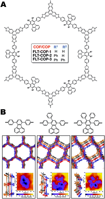 | ||
| Fig. 14 (A) Structure of FLT-COFs and covalent organic polymers (COPs). (B) Molecular dynamics (MD) simulations of the FLT-COF structures illustrating that the added steric hindrance from additional phenyl rings could disrupt the eclipsed packing of the COF layers. This disruption is attributed to the tri- and tetraphenylfluoranthene monomers inability to form crystalline COF structures. Reproduced from ref. 14 with permission from ACS Publications, copyright 2017. | ||
The previously discussed examples of “non-planarity” all describe monomer units whose topology is defined by bond torsions. However, there are many examples of curved aromatic systems, such as geodesic polyarenes, whose non-planarity is derived from internal strain or steric hindrance that cannot be relieved through a conformational change. Recently, Mateo-Alonso et al. synthesized a 2D-COF using a core-twisted polycyclic aromatic hydrocarbon (PAH) core (Fig. 15).13 The contorted hexabenzocoronene (HBC) used in this work projects the COF's three boronic acid groups out of plane, allowing the PAH cores to nest together like cups. Columns of PAHs stacked in alternating directions allows this unique COF to assemble into a chair-like lattice structure of such high crystallinity that the hexagonal structure can be observed directly using high temperature TEM images. The resulting COF has a surface area of 1300 m2 g−1, very close to the calculated theoretical value of 1570 m2 g−1.
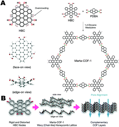 | ||
| Fig. 15 (A) Synthesis and structure of Marta-COF-1, and the contorted hexabenzocoronene monomer units. (B) The wavy 2D sheets of Marta-COF-1 are self-complementary resulting in excellent crystallinity and pore alignment. Reproduced from ref. 13 with permission from ACS Publications, copyright 2019. | ||
Together, these studies show that planarity in and of itself is not the only factor that determines the formation of stable COFs with high crystallinity. When the desired interlayer interaction is planar aromatic stacking, then the more planar the monomer system the better those interactions can be, and the better the overall COF properties. However, clever monomer selection is possible such that strong interlayer interactions can be enhanced through stackable monomer shapes. In these systems, it is not enough that the individual shapes match, linker choice is also very important as there must be a way for neighbouring stacks to properly orient with respect to each other in order to obtain crystalline structures.
Interlayer hydrogen bonding in 2D-COFs
Though most 2D-COFs reported in the literature rely on eclipsed stacking interactions between COF sheets, more recently researchers have been able to synthesize COFs whose layers are held together through hydrogen bonding interactions. One of the major challenges with using hydrogen bonding as a stabilizing or directing force between layers in COFs is that functional groups capable of hydrogen bonding will typically remain coplanar with the aromatic monomers rather than orient themselves between layers. In this part of the review, different designs and structural modifications used to achieve interlayer hydrogen bonding and their importance in applications will be discussed. These studies include not only experimental results, but also computational studies based on hypothetical 2D polymers which provide insight on how to design COFs with interlayer hydrogen bonds.In 2018, Banerjee and co-workers reported a series of imine-based COFs with extraordinary high chemical stability resulting from interlayer hydrogen bonding.44 In this paper, six different imine COFs have been constructed through direct condensation between 2,4,6-trimethoxy-1,3,5-benzenecarbaldehyde (TpOMe) with six different amines resulting in a series of COFs named: TpOMe-Tab, TpOMe-PaNO2, TpOMe-Pa1, TpOMe-BD(NO2)2, TpOMe-BPy, and TpOMe-Azo. The methoxy sidechain of the aldehyde monomer unit plays an important role as a hydrogen bond donor. With the exception of TpOMe-BD(NO2)2, this methoxy group lies nearly perpendicular to the adjacent layer facilitating the formation of an interlayer hydrogen bond. Consequently, the C–H⋯N hydrogen bonds form between the methoxy C–H of one layer and the imine nitrogen of the next layer (Fig. 16A and B). A range of six to twelve hydrogen bonds can be found in each set of stacked hexagons within the COFs. The steric hindrance of the methoxy group provides a sufficiently steric and hydrophobic environment around the hydrogen and imine bonds that serves to protect them from attack by water or acid during COF formation as well as hydrolysis under harsh conditions. These COFs exhibited exceptionally high chemical stability in extremely harsh environments such as strong acids (conc. H2SO4 18 M, conc. HCl 12 M; 7 d) and base (NaOH 9 M; 24 h). Further, the TpOMe-Azo COF could be converted into self-standing, continuous, crack-free COF membranes (COFMs) and studied for its potential in waste solvent treatment. These studies revealed that these membranes allow for high solvent flux for acetonitrile (280 L m−2 h−1 bar−1) and acetone (260 L m−2 h−1 bar−1). It was also found that these COFMs are suitable for sulfuric acid recovery as well as for the removal of toxic substances from drinking water.
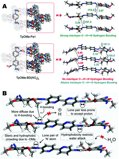 | ||
| Fig. 16 (A) Representation of TpOMe-Pa1 and TpOMe-BD(NO2)2 with hydrogen bonding between neighbouring COF layers and (B) the structural origin of the interlayer hydrogen bonding in TpOMe-BPy. Reproduced from ref. 44 Wiley-VCH Verlag GmbH & Co., copyright 2018. | ||
Furthermore, Banerjee and co-workers demonstrated the utility of hydrogen bond stabilization by synthesizing a redox active, imine-based COF,45 TpOMe-DAQ, for supercapacitor applications. Anthraquinone moieties in the TpOMe-DAQ COF exhibited reversible redox response and the chemical stability of the COF gained through interlayer hydrogen bonding resulted in the improved capacitance. Moreover, this COF could be fabricated into uniform, continuous thin sheets and utilized as a free-standing supercapacitor electrode material using aq. H2SO4 (2 M and 3 M) as an electrolyte. The chemical robustness of the COF allows for high areal capacity 1600 mF cm−2 (gravimetric 169 F g−1), and excellent stability over charge–discharge cycles (>100![[thin space (1/6-em)]](https://www.rsc.org/images/entities/char_2009.gif) 000 cycles).
000 cycles).
Urea functional groups have long been used in supramolecular receptors for their ability to donate and accept hydrogen bonds, though until recently, had yet to be incorporated into COF structures. Yaghi and coworkers reported the first COFs (COF-117 and COF-118) containing urea linkages as shown in Fig. 17A, expanding the scope of COF chemistry.8 The synthesis of COF-117 and COF-118 were carried out by condensation of 1,3,5-triformylphloroglucinol (TFP) with 1,4-phenylenediurea (BDU) and 1,1′-(3,3′-dimethyl-[1,1′-biphenyl]-4,4′-iyl)diurea (DMBDU) respectively. COF-117 exhibited a BET surface area of 114 m2 g−1; however, a relatively high BET surface area of 1524 m2 g−1 was observed for COF-118. The authors hypothesized that the low surface area of COF-117 resulted from deformation of the framework upon activation facilitated by the higher density (by weight percentage) of the flexible urea linkages. Many different conformations of the urea linkage are possible as shown in Fig. 17B. A consequence of the linkage flexibility was that the urea COFs could undergo reversible structural dynamics within their layers when they were subjected to the inclusion and removal of guest molecules. The reversible dynamics of COFs was attributed to both C–N bond rotation and the disruption of interlayer hydrogen bonding. This was observed by FT-IR spectroscopy through the shift of both the C![[double bond, length as m-dash]](https://www.rsc.org/images/entities/char_e001.gif) O and N–H stretching frequencies before and after exposure to a guest molecule (acetonitrile). A blue shift was noted for both COFs compared to guest molecule-free conditions.
O and N–H stretching frequencies before and after exposure to a guest molecule (acetonitrile). A blue shift was noted for both COFs compared to guest molecule-free conditions.
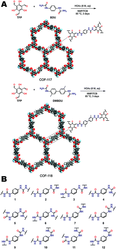 | ||
| Fig. 17 (A) Synthesis and structures of COF-117 and COF-118. (B) Different possible conformations of the diurea linker that can potentially complicate the synthesis of urea-linked COFs. Reproduced from ref. 8 with permission from ACS Publications, copyright 2018. | ||
In 2019, Li and coworkers reported a triazine based COF (PDC-MA-COF) which has interlayer hydrogen bonding for supercapacitor applications.46 PDC-MA-COF has been synthesized using 1,4-piperazinedicarboxaldehyde (PDC) and melamine (MA) as the building monomers via Schiff-base condensation. The BET surface area of PDC-MA-COF was 748 m2 g−1 with an average pore size of 1.9 nm. In this design, the interlayer hydrogen bonding is formed between the C–H and N of two adjacent piperazine rings within the COF. Within a hexagonal unit of PDC-MA-COF, there are 12 hydrogen bonds between two adjacent piperazine rings. In other words, along the vertical direction two H-bonds occur between every two piperazine rings of each hexagonal unit of the COF. Due to the existence of interlayer C–H⋯N H-bonding, it can “lock” the relative distance between atoms in two adjacent layers, avoiding interlayer slipping. Decreasing interlayer slippage results in a more ordered pore structure within the COF, which in turn enabled fast charge transfer between the electrode interface and triazine units. In addition, due to the “locking” effect of interlayer H-bonding, the stability of COF was improved providing a good capacitance retention with a good thermal stability and the excellent electrochemical stability needed for a supercapacitor electrode material. The PDC-MA-COF displayed excellent electrochemical performances with a maximum specific capacitance of 335 F g−1 in a three-electrode system and 94 F g−1 in a two-electrode system at the current density of 1.0 A g−1. At the same time, the specific capacitance retention reached 74% at the current density range of 1.0–10 A g−1. An asymmetric supercapacitor assembled from PDC-MA-COF//AC (activated carbon) also showed a high energy density (29.2 W h kg−1) as well as an excellent cyclic stability (88% of the capacitance after 20![[thin space (1/6-em)]](https://www.rsc.org/images/entities/char_2009.gif) 000 GCD cycles).6 The excellent electrochemical characteristics of PDC-MA-COF were attributed to the high surface area, high nitrogen content, abundant pores, and multiple interlayer C–H⋯N H-bonding.
000 GCD cycles).6 The excellent electrochemical characteristics of PDC-MA-COF were attributed to the high surface area, high nitrogen content, abundant pores, and multiple interlayer C–H⋯N H-bonding.
In 2016, Wetzel and coworkers performed atomistic simulations to design molecular structures for 2D polymer materials to achieve more ductile fracture behavior compared to graphene.9 For this purpose, the authors have proposed a new class of 2D polymer hybrids called “graphylene”. In detail, graphylene can be explained as a hybrid of graphene and polyethylene, in which benzene rings are connected by short polyethylene bridge units. In this study, a specific configuration of graphylene denoted as “Gr-E-2”, where two ethylene units are found between benzene rings, was selected due to it possessing the closest structure to graphene. The most stable configuration of Gr-E-2 was determined from among two configurations, “System A” (the carbon atoms are almost co-planar with the methylene bond angles accommodated in the plane) and “System B” (the carbon atoms in the polyethylene units are out-of-plane compared to the benzene rings) using density functional theory (DFT). The results revealed that System B has rectangular symmetry, higher density, and lower energy with a compact structure compared to System A. Further, the initiation of crack growth and propagation behaviour of Gr-E-2 system B conformation was studied through molecular dynamics (MD) simulations and compared with graphene. The results revealed that Gr-E-2 system B configuration has higher flaw tolerance (×3 graphene), higher fracture energy release during propagation (×2 graphene), and larger quasi-static critical fracture energy than graphene. This study reveals that 2D polymers can be modified to obtain a balance of fracture robustness with mechanical toughness and strength. After this initial study, E. D. Wetzel et al. extended this study in 2018 by including hydrogen bonded 2D polymers.47 In this paper they have designed a “plane-extended”, 2D para-aromatic polyamide polymer called “graphamid”. Graphamid has a similar chemical structure to Kevlar, a linear poly(p-phenylene terephthalamide) (PPTA). According to the atomistic calculations, they showed that graphamid consists of covalently bonded sheets, linked by hydrogen bonds. The stiffness, strength and fracture behaviour of both monolayer and multilayer graphamid was predicted using atomistic simulations and the results were compared with graphene, graphylene and PPTA (Fig. 18A–D). Results showed that due to strong interlayer hydrogen bonds between layers, graphamid has superior shear stiffness and shear strength (6–8 GPa) as compared to graphene and graphylene, which have significantly weaker van der Waals (vdW) interactions between layers (Fig. 18E). The atomistic fracture simulation results further revealed that there is an increase in fracture toughness for graphamid in contrast to vdW solids. The mechanical properties of graphamid are comparable to hydrogen bonding graphene oxide (GO) papers. Graphamid shows these excellent properties due to hydrogen bonds formed between the amide groups in neighbouring layers. These amide groups are present at high per-area density, resulting in a high density of interlayer hydrogen bonds. Further, the equilibrium conformation of graphamid is planar with the amide groups rotated out of plane. As a result, loads are transferred to the adjacent layers during fracture, lessening stress concentration around a crack defect and making graphamid a flaw tolerant and robust material. These results suggest that 2D hydrogen bonded polymers such as graphamid should be considered by experimental researchers as targets for lightweight materials with superior properties.
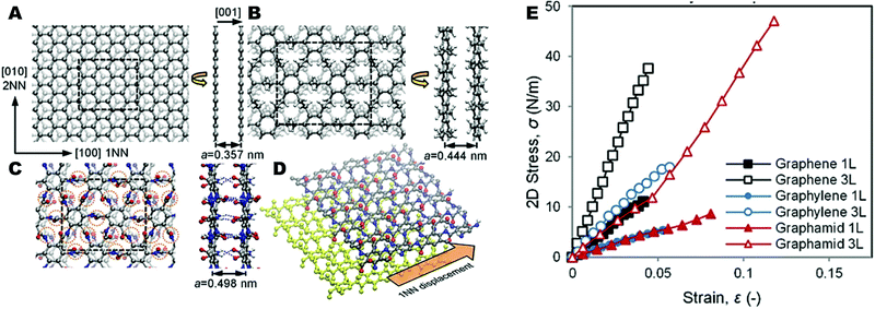 | ||
| Fig. 18 Bilayer structures of (A) graphene, (B) graphylene, and (C) graphamid. (D) Graphamid lateral displacement and (E) stress vs. strain curves for graphene, graphylene, and graphamid at 1L and 3L. Reproduced from ref. 9 with permission from the Royal Society of Chemistry, copyright 2016. | ||
Future directions and outlook
Though the importance of non-covalent interactions in 2D-COFs is now becoming a major area of research in the field, the opportunities for advances have just begun to be realized. There are a number of major challenges still to be tackled in 2D-COF chemistry and it seems that the appreciation for supramolecular design in COFs is enabling researchers to solve them. One major limitation of many 2D materials including graphene and COFs is that it is extremely difficult to process them with conventional techniques used in polymer chemistry such as spin or drop casting due to their low solubility. Recently, Dichtel and co-workers reported that under strong acidic conditions 2D-COFs could be dissolved without damaging their primary structure, and cast into porous, crystalline membranes.48 This work was enabled by the understanding that the protonation of the imine groups would form highly cationic sheets where the interlayer interactions are essentially “switched off”. Treatment of the cast films with base turns the interactions back on thereby enabling the dispersions to be processed into morphologies such as thin films or colloidal materials. Recently, theoretical work has explored the potential for binding metal ions between layers in COFs enabling them to be used in new electronic devices or batteries.49,50 While these structures have not yet been realized, their potential makes them an attractive target for further research and the importance of the interlayer interactions becomes paramount.The introduction of supramolecular chemical design will continue this evolution. COFs will continue to see promising advances towards their use in batteries, electronic devices and mechanically tough materials as greater structural control and fidelity are achieved through the principles of non-covalent chemical design. 2D-COFs are already a vibrant and versatile set of materials which have grown significantly through the development of dynamic covalent chemical methods to make them and structural design to give them function. The next frontier for 2D-COFs may very well be to take inspiration from supramolecular chemistry to design new form and function into these materials.
Conflicts of interest
There are no conflicts to declare.References
- A. P. Côté, A. I. Benin, N. W. Ockwig, M. Keeffe, A. J. Matzger and O. M. Yaghi, Science, 2005, 310, 1166 CrossRef PubMed
.
- X. Feng, X. Ding and D. Jiang, Chem. Soc. Rev., 2012, 41, 6010–6022 RSC
.
- J. Jiang, Y. Zhao and O. M. Yaghi, J. Am. Chem. Soc., 2016, 138, 3255–3265 CrossRef CAS PubMed
.
- R. P. Bisbey and W. R. Dichtel, ACS Cent. Sci., 2017, 3, 533–543 CrossRef CAS
.
- M. S. Lohse and T. Bein, Adv. Funct. Mater., 2018, 28, 1705553 CrossRef
.
- S. B. Alahakoon, G. Occhialini, G. T. McCandless, A. A. K. Karunathilake, S. O. Nielsen and R. A. Smaldone, CrystEngComm, 2017, 19, 4882–4885 RSC
.
- X. Chen, M. Addicoat, S. Irle, A. Nagai and D. Jiang, J. Am. Chem. Soc., 2013, 135, 546–549 CrossRef CAS
.
- C. Zhao, C. S. Diercks, C. Zhu, N. Hanikel, X. Pei and O. M. Yaghi, J. Am. Chem. Soc., 2018, 140, 16438–16441 CrossRef CAS PubMed
.
- E. Sandoz-Rosado, T. D. Beaudet, R. Balu and E. D. Wetzel, Nanoscale, 2016, 8, 10947–10955 RSC
.
- E. L. Spitler, B. T. Koo, J. L. Novotney, J. W. Colson, F. J. Uribe-Romo, G. D. Gutierrez, P. Clancy and W. R. Dichtel, J. Am. Chem. Soc., 2011, 133, 19416–19421 CrossRef CAS PubMed
.
- S. B. Alahakoon, G. T. McCandless, A. A. K. Karunathilake, C. M. Thompson and R. A. Smaldone, Chem. – Eur. J., 2017, 23, 4255–4259 CrossRef CAS PubMed
.
- L. M. Salonen, D. D. Medina, E. Carbó-Argibay, M. G. Goesten, L. Mafra, N. Guldris, J. M. Rotter, D. G. Stroppa and C. Rodríguez-Abreu, Chem. Commun., 2016, 52, 7986–7989 RSC
.
- M. Martínez-Abadía, C. T. Stoppiello, K. Strutynski, B. Lerma-Berlanga, C. Martí-Gastaldo, A. Saeki, M. Melle-Franco, A. N. Khlobystov and A. Mateo-Alonso, J. Am. Chem. Soc., 2019, 141, 14403–14410 CrossRef PubMed
.
- C. M. Thompson, G. Occhialini, G. T. McCandless, S. B. Alahakoon, V. Cameron, S. O. Nielsen and R. A. Smaldone, J. Am. Chem. Soc., 2017, 139, 10506–10513 CrossRef CAS
.
- A. Halder, S. Kandambeth, B. P. Biswal, G. Kaur, N. C. Roy, M. Addicoat, J. K. Salunke, S. Banerjee, K. Vanka, T. Heine, S. Verma and R. Banerjee, Angew. Chem., Int. Ed., 2016, 55, 7806–7810 CrossRef CAS PubMed
.
- S. Duhović and M. Dincă, Chem. Mater., 2015, 27, 5487–5490 CrossRef
.
- D. D. Medina, M. L. Petrus, A. N. Jumabekov, J. T. Margraf, S. Weinberger, J. M. Rotter, T. Clark and T. Bein, ACS Nano, 2017, 11, 2706–2713 CrossRef CAS PubMed
.
- Z. Meng, R. M. Stolz and K. A. Mirica, J. Am. Chem. Soc., 2019, 141, 11929–11937 CrossRef CAS PubMed
.
- D. D. Medina, T. Sick and T. Bein, Adv. Energy Mater., 2017, 7, 1700387 CrossRef
.
- C. R. DeBlase, K. E. Silberstein, T.-T. Truong, H. D. Abruña and W. R. Dichtel, J. Am. Chem. Soc., 2013, 135, 16821–16824 CrossRef CAS PubMed
.
- D. A. Vazquez-Molina, G. S. Mohammad-Pour, C. Lee, M. W. Logan, X. Duan, J. K. Harper and F. J. Uribe-Romo, J. Am. Chem. Soc., 2016, 138, 9767–9770 CrossRef CAS PubMed
.
- S. Dalapati, S. Jin, J. Gao, Y. Xu, A. Nagai and D. Jiang, J. Am. Chem. Soc., 2013, 135, 17310–17313 CrossRef CAS PubMed
.
- J. W. Crowe, L. A. Baldwin and P. L. McGrier, J. Am. Chem. Soc., 2016, 138, 10120–10123 CrossRef CAS PubMed
.
- S. Dalapati, E. Jin, M. Addicoat, T. Heine and D. Jiang, J. Am. Chem. Soc., 2016, 138, 5797–5800 CrossRef CAS PubMed
.
- P. Albacete, J. I. Martínez, X. Li, A. López-Moreno, S. A. Mena-Hernando, A. E. Platero-Prats, C. Montoro, K. P. Loh, E. M. Pérez and F. Zamora, J. Am. Chem. Soc., 2018, 140, 12922–12929 CrossRef CAS PubMed
.
- X. Li, Q. Gao, J. Wang, Y. Chen, Z.-H. Chen, H.-S. Xu, W. Tang, K. Leng, G.-H. Ning, J. Wu, Q.-H. Xu, S. Y. Quek, Y. Lu and K. P. Loh, Nat. Commun., 2018, 9, 2335 CrossRef PubMed
.
- S. Dalapati, C. Gu and D. Jiang, Small, 2016, 12, 6513–6527 CrossRef CAS PubMed
.
- M. O’Keeffe, Chem. Soc. Rev., 2009, 38, 1215–1217 RSC
.
- M. J. Kalmutzki, N. Hanikel and O. M. Yaghi, Sci. Adv., 2018, 4, eaat9180 CrossRef CAS PubMed
.
- C. A. Hunter and J. K. M. Sanders, J. Am. Chem. Soc., 1990, 112, 5525–5534 CrossRef CAS
.
- R. E. Gillard, F. M. Raymo and J. F. Stoddart, Chem. – Eur. J., 1997, 3, 1933–1940 CrossRef CAS
.
- M. S. Cubberley and B. L. Iverson, Curr. Opin. Chem. Biol., 2001, 5, 650–653 CrossRef CAS PubMed
.
-
C. J. Bruns and J. F. Stoddart, in Hierarchical Macromolecular Structures: 60 Years after the Staudinger Nobel Prize I, ed. V. Percec, Springer International Publishing, 2013, pp. 271–294 DOI:10.1007/12_2013_245
.
- C. R. Martinez and B. L. Iverson, Chem. Sci., 2012, 3, 2191–2201 RSC
.
- B. J. Smith, N. Hwang, A. D. Chavez, J. L. Novotney and W. R. Dichtel, Chem. Commun., 2015, 51, 7532–7535 RSC
.
- W. A. Braunecker, K. E. Hurst, K. G. Ray, Z. R. Owczarczyk, M. B. Martinez, N. Leick, A. Keuhlen, A. Sellinger and J. C. Johnson, Cryst. Growth Des., 2018, 18, 4160–4166 CrossRef CAS
.
- L. Stegbauer, K. Schwinghammer and B. V. Lotsch, Chem. Sci., 2014, 5, 2789–2793 RSC
.
- F. J. Uribe-Romo, C. J. Doonan, H. Furukawa, K. Oisaki and O. M. Yaghi, J. Am. Chem. Soc., 2011, 133, 11478–11481 CrossRef CAS PubMed
.
- S. B. Alahakoon, C. M. Thompson, A. X. Nguyen, G. Occhialini, G. T. McCandless and R. A. Smaldone, Chem. Commun., 2016, 52, 2843–2845 RSC
.
- S. Dalapati, M. Addicoat, S. Jin, T. Sakurai, J. Gao, H. Xu, S. Irle, S. Seki and D. Jiang, Nat. Commun., 2015, 6, 7786 CrossRef CAS PubMed
.
- F. Auras, L. Ascherl, A. H. Hakimioun, J. T. Margraf, F. C. Hanusch, S. Reuter, D. Bessinger, M. Döblinger, C. Hettstedt, K. Karaghiosoff, S. Herbert, P. Knochel, T. Clark and T. Bein, J. Am. Chem. Soc., 2016, 138, 16703–16710 CrossRef CAS PubMed
.
- T. Sick, J. M. Rotter, S. Reuter, S. Kandambeth, N. N. Bach, M. Döblinger, J. Merz, T. Clark, T. B. Marder, T. Bein and D. D. Medina, J. Am. Chem. Soc., 2019, 141, 12570–12581 CrossRef CAS PubMed
.
- L. Ascherl, T. Sick, J. T. Margraf, S. H. Lapidus, M. Calik, C. Hettstedt, K. Karaghiosoff, M. Döblinger, T. Clark, K. W. Chapman, F. Auras and T. Bein, Nat. Chem., 2016, 8, 310–316 CrossRef CAS
.
- A. Halder, S. Karak, M. Addicoat, S. Bera, A. Chakraborty, S. H. Kunjattu, P. Pachfule, T. Heine and R. Banerjee, Angew. Chem., Int. Ed., 2018, 57, 5797–5802 CrossRef CAS PubMed
.
- A. Halder, M. Ghosh, M. A. Khayum, S. Bera, M. Addicoat, H. S. Sasmal, S. Karak, S. Kurungot and R. Banerjee, J. Am. Chem. Soc., 2018, 140, 10941–10945 CrossRef CAS PubMed
.
- L. Li, F. Lu, R. Xue, B. Ma, Q. Li, N. Wu, H. Liu, W. Yao, H. Guo and W. Yang, ACS Appl. Mater. Interfaces, 2019, 11, 26355–26363 CrossRef CAS PubMed
.
- E. Sandoz-Rosado, T. D. Beaudet, J. W. Andzelm and E. D. Wetzel, Sci. Rep., 2018, 8, 3708 CrossRef PubMed
.
- D. W. Burke, C. Sun, I. Castano, N. C. Flanders, A. M. Evans, E. Vitaku, L. X. Chen, N. C. Gianneschi and W. R. Dichtel, Angew. Chem., Int. Ed., 2019 DOI:10.1002/anie.201913975
.
- S. Pakhira, K. P. Lucht and J. L. Mendoza-Cortes, J. Phys. Chem. C, 2017, 121, 21160–21170 CrossRef CAS
.
- S. Pakhira and J. L. Mendoza-Cortes, Phys. Chem. Chem. Phys., 2019, 21, 8785–8796 RSC
.
| This journal is © The Royal Society of Chemistry 2020 |


