
Confined growth of ordered organic frameworks at an interface
Yinghua
Jin
a,
Yiming
Hu
a,
Michael
Ortiz
a,
Shaofeng
Huang
a,
Yanqing
Ge
 ab and
Wei
Zhang
*a
ab and
Wei
Zhang
*a
aDepartment of Chemistry, University of Colorado, Boulder, CO 80309, USA. E-mail: wei.zhang@colorado.edu
bSchool of Chemistry and Pharmaceutical Engineering, Shandong First Medical University & Shandong Academy of Medical Sciences, Taian, 27106, China
First published on 29th June 2020
Abstract
Given their modular synthesis, unique structural features and rich functionality, structurally ordered covalent organic frameworks (COFs) and covalent monolayers have shown great potential in a broad range of applications, such as catalysis, molecular separation, energy storage, light harvesting, etc. The synthesis of COF thin films and covalent monolayers mainly utilizes dynamic covalent chemistry (DCvC), which relies on the reversible formation and breaking of rather strong covalent bonds within molecules under certain external stimuli. Such reversible reaction conditions enable a self-correction mechanism, which can selectively resolve defect sites leading to the formation of highly ordered COF films under thermodynamic control. Novel techniques to obtain single-layer covalent nanosheets have spread throughout recent literature. Emerging interfacial polymerization techniques (e.g., air–water, liquid–liquid, liquid–solid, etc.) have been employed to successfully synthesize crystalline COF thin films from a variety of starting building blocks. Although the growth of ordered frameworks at the interface represents a rapidly developing field, the reversible reactions suitable for the synthesis of thin films or monolayers are still very limited. The identification and development of new dynamic reactions and interfacial polymerization conditions would be critical for the further development of COF thin films and covalent monolayer materials. This review covers the recent design and synthesis of COF thin films and covalent monolayers as well as their property study. The fundamental working mechanisms of different surface and interfacial polymerization and the current challenges and opportunities in this rapidly growing field are presented.
 Yinghua Jin | Yinghua (Alice) Jin received her BS in Chemistry from Peking University in 2000. She obtained her PhD in Chemistry under the supervision of Prof. Robert M. Coates from University of Illinois at Urbana-Champaign in 2006. Her research interests include development of novel organic functional materials and their applications in the energy and biomedical fields. |
 Yiming Hu | Yiming Hu received his bachelor's degree in chemistry from Lanzhou University, China. In 2016, he joined Wei Zhang's group in the University of Colorado, Boulder. His current research is focused on the development of crystalline polymers and their applications in the energy fields. |
 Michael Ortiz | Michael Ortiz received his BS degree in Chemistry from The University of Texas at Austin in 2014. He is currently completing his doctorate under the supervision of Professor Zhang. His research interests consist of the synthesis of three dimensional molecular cages and the photophysical characterization of these novel compounds. |
 Shaofeng Huang | Shaofeng Huang received his bachelor's degree in Chemistry from Fudan University in 2018. After graduation, Shaofeng started his PhD study under the supervision of Professor Wei Zhang at the Department of Chemistry, University of Colorado, Boulder. His current research interests focus on the design and synthesis of covalent organic frameworks (COFs) with novel functional groups as well as topologies. |
 Yanqing Ge | Yanqing Ge received his PhD in organic chemistry from Shandong University in 2010. Currently he is a full professor at Taishan Medical University. His main research interests are the development of new small molecules for chemical biology study and chemodosimeters for bioimaging. He is also involved in alkyne metathesis catalyst development and covalent organic framework study. |
 Wei Zhang | Wei Zhang received his BS in Chemistry from Peking University in 2000, and his PhD in Chemistry from University of Illinois at Urbana-Champaign (UIUC) in 2005. After a postdoc stint at MIT, he started his independent career at the Department of Chemistry and Biochemistry at University of Colorado Boulder in 2008, and was promoted to Associate and Full Professor in 2014 and 2018, respectively. His research is focused on utilizing dynamic covalent chemistry to develop novel organic and hybrid functional materials targeting a broad range of environmental, energy and biological applications. |
Key learning points(1) Pros and cons of different interfaces: solid–liquid, solid–gas, liquid–liquid, and liquid–gas(2) Monomer design principles: tessellation requirement, monomer–surface interactions (3) Suitable reactions and strategies to yield ordered structures with minimal defects (4) Characterization methods and techniques for COF membranes and monolayers (5) Applications of COF membranes and monolayers in nanofiltration, catalysis, and molecular separation. |
1. Introduction
Covalent organic frameworks represent a novel class of rapidly emerging porous organic materials.1 They have attracted tremendous research interest because of their customizable design, unique chemical structures, and potential applications in gas storage and separation, energy storage, catalysis and optoelectronic materials. By utilizing dynamic covalent chemistry (DCvC)2 under solvothermal conditions, which involves reversible covalent bond formation (self-correction enabled), numerous COF structures with homo- or hetero-pores, high crystallinity, and usually high thermal stability have been developed. However, COF materials are usually obtained as solid powders, which are not soluble in most organic solvents, thus making it very difficult to process/fabricate them, particularly into thin films or membranes. This represents a significant drawback for their wide practical applications.Interfacial polymerization can be applied to the synthesis of polymer thin films or even monolayers directly from monomeric building blocks (bottom-up design). Interfacial polymerization has been widely used to prepare ultrathin functional layers and capsules at the interface between two phases, such as air–water, liquid–liquid, and solid–liquid. Starting monomers are usually dispersed in two different phases causing reactions to occur only at the interfaces. Alternatively, if one monomer resides on the surface of one phase, the catalyst or the other substrate can be slowly introduced to the interface, thus allowing the reaction to occur. Due to the limitation of the mass transfer of starting materials, polymers grown at the interface tend to be thin, with the formation of a covalent monolayer as the extreme case. Depending on the reactivity of the monomers, concentration, solvent combination, reaction temperature, etc., the thickness of the obtained polymer sheets can vary significantly. The development of covalent monolayers (if structurally ordered, also called two-dimensional polymers, 2DPs) represents a rapidly growing field, pioneered by Schlüter, who first introduced the concept of 2DPs in 2009.3 In this review, for clarification, the term “COF monolayer” is used for single-layer frameworks, while “COF thin films” and “COF membranes” are used for few-layer or much thicker bulk COF materials prepared through interfacial polymerization. All these polymer structures prepared on a surface are labeled as COFa or COFa+b, where a and b represent the monomer chemical structure numbers.
Within the past ten years or so, there has been quite some progress in covalent monolayer and COF thin film synthesis through interfacial polymerization. The obtained materials have shown great potential in various applications, such as host–guest chemistry, water purification, energy storage, etc. This review covers basic concepts and principles and summarizes the recent progress in this rapidly growing field, with a particular focus on the rational design of building blocks, selection of substrate surface, as well as pros and cons of each interfacial polymerization (air–water, liquid–liquid, vs. liquid–solid). First, the properties and functions of different surfaces as well as the interactions between surface and monomers (e.g., adsorption and desorption kinetics) will be discussed. The building block requirements will then be reviewed, which includes tessellation requirement, reactivity and alignment of functional groups, as well as reactant ratios and concentrations. We will discuss various covalent organic reactions for the framework synthesis at the interface, reaction kinetics, bond formation reversibility, external stimuli, and characterization techniques for COFs formed on a surface. Subsequently, we will review some recent examples of covalent monolayers and COF thin films or membranes synthesized at the air–liquid, liquid–liquid, liquid–solid, and solid–vapor interface. Last but not least, in the summary and outlook section, some remaining challenges in this rapidly growing field will be discussed. This review is not intended to be a comprehensive survey of literature reports, rather it provides a tutorial view of the research field by presenting representative literature examples for the discussed topics. Although we focus on dynamic covalent reactions, which have clear advantages in constructing ordered framework structures by allowing the error-correction mechanism, irreversible reactions are also discussed to provide comparisons and in-depth complete view of the field.
2. Surface and interface properties
Matter has three main phases, namely gas, liquid, and solid. The physical boundary between two contacting phases is called an interface. An interface is a very thin layer with the thickness typically ranging from one to five atomic layers. The word “surface” is used when we need to describe the physical boundary of only one of the contacting phases. Surface chemistry generally refers to the chemical phenomena occurring at solid–gas, solid–liquid, liquid–liquid, and liquid–gas interfaces. Less notable techniques include a solid–solid or gas–gas interface, as molecular movement in these two cases is either highly restricted (in the former) or not restricted at all (in the latter, no distinct interface). The molecules at an interface behave very differently from those in the bulk phase and molecular movement is highly dependent on the surface properties. The phenomenon of on-surface molecular accumulation at an interface is called adsorption. In this context, the adsorbate is the substance that is adsorbed, and the adsorbent is the substrate on which adsorption occurs. The layer of adsorbed molecules formed on a surface is called an adlayer. When an adlayer is one atom thick, it is called a monolayer, whereas thicker adlayers are called multilayers. If chemical bonds are formed between the surface and the adsorbate during the adsorption, the process is classified as chemisorption, whereas if a weak attractive force (e.g. van der Waals interaction) is operative, it is classified as physisorption. Adsorption is a reversible process; adsorbates can desorb, rearrange, or react with other absorbates co-adsorbed on the surface. We are particularly interested in chemical reactions of absorbates to form a monolayer or a few layers of 2D COFs on a surface.2.1 Surface adsorption/desorption and diffusion
Substrates greatly influence adsorption isotherms, diffusion barriers, molecular interactions with the surface, and adsorption and desorption kinetics, and as such control the outcome of the on-surface reactions. To obtain on-surface 2D COFs with minimal defects and high polymerization degree, both adsorption and diffusion properties of molecules on a surface should be considered. Adsorption and diffusion of molecules are two distinct processes: the former defines the process and outcome of molecular deposition on a surface and the latter describes the mobility of the adsorbed molecules on a surface from one adsorption site to another. Interactions between adsorbate molecules and surface are mainly weak supramolecular (e.g. van der Waals attractions, dipole forces, repulsion due to orbital overlap) or strong chemical bonding (charge transfer or charge redistribution) interactions. An adsorbed molecule can be desorbed through the opposite process of adsorption back into the bulk phase (desorption) or migrate along the surface to another adsorption site (diffusion) in the adsorbed state. The diffusivity of adsorbed molecules increases the overall mass flux (the rate of mass flow per unit area) on a surface by creating additional internal fluxes, thus increasing the surface coverage and surface reaction probability.Both desorption and diffusion play important roles in the synthesis of surface COFs with minimal defects by allowing error correction. When the adsorbed phase is immobile with high desorption energy and diffusion barrier, the error-correction becomes nearly impossible. Fortunately, desorption and diffusion behaviors of adsorbates are sensitive to temperature and fractional surface coverage. By controlling molecular flux and/or temperature, it is possible to enable microscopic error correction on a surface through desorption and diffusion. For example, an ordered H-bonded supramolecular phase of 1,4-benzenediboronic acid (BDBA) was found to form at a very low deposition flux, as low as about 0.005 ML (monolayer) min−1 (corresponding to one monolayer in about 3 hours), at room temperature on the Ag(111) surface.4 When the molecules were deposited under a high deposition flux (of the order of about 0.1 ML min−1), it triggered in situ polymerization, which kinetically traps BDBA molecules and limits their desorption and diffusion, and thus was unable to yield an ordered supramolecular network. The temperature effect on the self-assembled monolayer formation was also observed when a solution sample of a diboronic acid was deposited on a highly oriented pyrolytic graphite (HOPG) surface. At room temperature, quaterphenyl diboronic acid forms a disordered adsorption layer, whereas under elevated temperature (50 °C) a well-ordered self-assembled supramolecular monolayer is formed. It indicates that thermal activation is required to enable the surface mobility of molecules and facilitate their self-assembly.5
Ordered monolayers, either noncovalent or covalent, are preferably formed under equilibrium growth conditions, where the adsorbed molecules have the capability to freely desorb and diffuse to explore the most favorable thermodynamic sites. Increasing the temperature could provide sufficient energy for surface molecules to desorb and diffuse, but at the same time activate premature formation of chemical bonds between adsorbates. Surface monolayer formation is a delicate process involving adsorption, desorption, diffusion, and reaction, where surface–molecule and molecule–molecule interactions play critical roles. Controlling the kinetics and equilibrium of such physical and chemical processes is central to managing on-surface reactions. In this section, we will discuss the properties of various surfaces and their roles in the formation of surface-confined COFs.
2.2 Solid surfaces
Although most natural solids have amorphous surfaces, well-defined crystalline surfaces are preferred in on-surface synthesis of COFs to allow convenient analysis of grafted surfaces after chemical reactions and to better understand the adsorption/desorption, diffusion, and reaction process of monomers. In this section, we will discuss the most widely used solid surfaces, crystalline metal surfaces, highly oriented pyrolytic graphite (HOPG) surfaces, as well as some non-conductive surfaces.2.2.1.1 Crystalline faces. Crystalline metal surfaces have been frequently used in surface chemistry. Most metals crystallize in either a face-centered cubic (fcc) structure (Fig. 1), where each atom has 12 closest neighbors, or a body-centered cubic (bcc) structure, where each atom has 8 closest neighbors. The three most frequently used metals in the interfacial synthesis of COFs are Au, Ag, and Cu, all of which pack in face-centered cubic structures. The (111) crystal faces of these fcc packed metals, i.e. Cu(111), Ag(111), and Au(111), have been the most widely used surfaces. As shown in the unit cells of 2D surface structures of fcc crystal surfaces (Fig. 1), fcc(111) faces consist of equivalent surface atoms packed with the highest surface atom density, providing a smooth and isotropic surface at the atomic scale. Three adsorption sites are available in a fcc(111) face, on-top sites (above a single atom), bridging sites between two atoms, and hollow sites between three atoms. The surface of fcc(100) is also relatively smooth and isotropic, consisting of equivalent surface atoms however packed less densely in a square grid compared to the hexagonal dense packing of surface atoms in fcc(111). Due to the different local symmetries of surface atoms, fcc(100) provides larger hollow adsorption sites between four atoms compared to the hollow coordination sites between three atoms in fcc(111). In great contrast to fcc(111) and (100) faces, the fcc(110) face is atomically rough with lattice-scale corrugation and tends to be highly anisotropic. The atoms in one direction are densely packed, whereas there is a substantial distance between two atoms in the orthogonal direction, leading to the formation of gaps between rows of atoms. Therefore, the second layer atoms are also exposed in fcc(110), providing varieties of adsorption sites including on-top sites, two different bridging sites (short) between two atoms in a single row or between two atoms in adjacent rows (long), and higher coordination sites in the grooves.
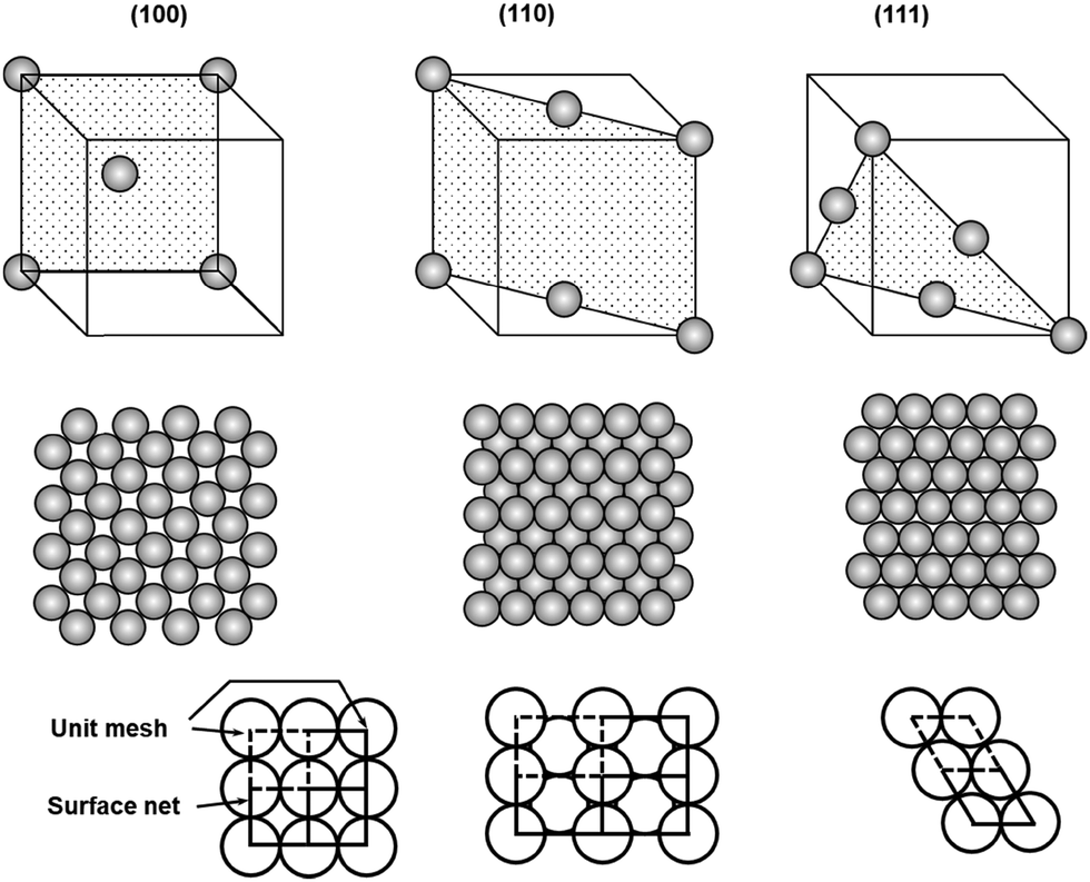 | ||
| Fig. 1 Unit cells and atomic packings of low index faces of face centered cubic crystals, fcc(100), (110), and (111). | ||
Given the substantial difference in surface atom packing, adsorption sites, and coordination geometries, three fcc crystalline faces have shown interesting properties in the adsorption, assembly, and reaction of on-surface molecules. Abel and Clair have demonstrated that 1,4-benzenediboronic acid (BDBA) has strong interactions with Ag(100) and forms a self-assembled monolayer of a H-bonded supramolecular network at a broad range of molecular flux under ultrahigh vacuum conditions. However, when Ag(111) was used as the surface, such supramolecular assembly can only form at a very low deposition flux (0.005 ML min−1).4,6 The supramolecular network slowly transforms into to a full monolayer of 2D polymer on Ag(100), whereas substantial desorption was observed over the course of polymerization on Ag(111), resulting in lower surface coverage of the polymer layer compared to the original supramolecular network. These results indicate the importance of metal surfaces, which have a significant influence on surface–molecule interactions, absorbate reactivity, and thus the formation of COFs.
Although an isotropic crystalline metal surface, e.g. fcc(111) or fcc(100), is generally preferred to minimize unnecessary complexity caused by the surface anisotropy, a corrugated surface can be used to direct a specific orientation of absorbates. Hecht and Grill et al. reported substrate-directed hierarchical growth of a tetraphenylporphyrin (TPP) framework using a corrugated metal surface.7 The reconstructed Au(100) surface with a quasihexagonal (5 × 20) superstructure has weak corrugation (>0.7 Å) with an intermolecular distance of 14.4 Å between the rows. This distance closely matches the intermolecular distance of the TPP unit, and thus such a corrugated surface adsorbs the monomer, trans-Br2I2TPP (1), in a templated fashion as seen in Fig. 2. After selectively activating iodine-phenyl coupling reaction at 120 °C, linear molecular chains aligned in a preferred angle of ∼51° relative to the atomic rows of the Au(100) surface were observed (Fig. 2b–d). Upon raising the temperature to 250 °C, phenyl-bromine coupling was activated, linking the linear polymer chains to form a network structure in a well-defined orientation with respect to the substrate (Fig. 2e). In contrast, under identical conditions, such a well-aligned angular distribution of polymer chains was not observed on an isotropic Au(111) surface, and a much smaller sized network was formed, demonstrating the potential advantage of corrugated anisotropic surfaces as adsorbent materials.
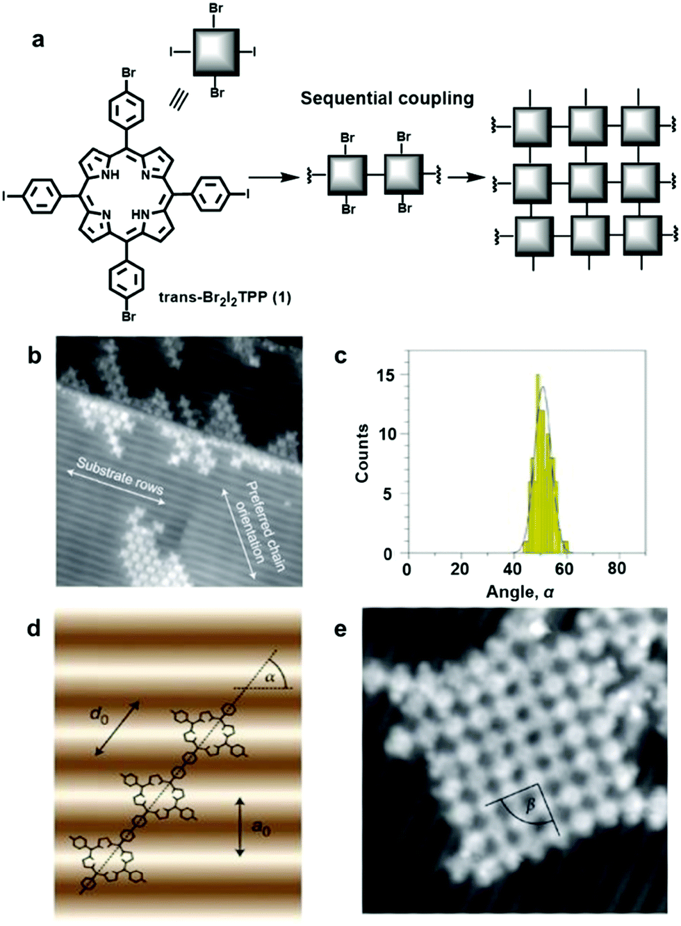 | ||
| Fig. 2 Controlling covalent linking using the corrugated reconstructed Au(100) surface: (a) synthesis of the network from the monomer, trans-Br2I2TPP (1); (b) scanning tunneling microscopy (STM) image of trans-Br2TPP linear chains formed through initial iodine-phenyl coupling; (c) angular distribution of the linear chains in (a); (d) a linear polymer chain with the preferred orientation on the Au(100) surface with α = 55° (a0 =1.44 nm and d0 =1.76 nm): (e) STM image (20 × 20 nm2) of a single molecular network after coupling of Br2TPP molecular chains. Reproduced with permission from ref. 7, Copyright 2012, Springer Nature. | ||
2.2.1.2 Catalytic activity. The inherent catalytic activity of select metal surfaces is well-acknowledged in surface chemistry. It has been reported that Ag, Au, and Cu surfaces can effectively catalyze boronic acid dehydration, imine condensation, and various cross coupling reactions. Due to the distinct surface nature, such as valence characteristics, electronic contributions, and surface restructure upon adsorption, each metal preferentially catalyzes some reactions over others. Although many reports have illustrated different reactivities of different metal surfaces, there has been limited experimental and theoretical information on the mechanistic insight into such catalytic activities, e.g. geometry of active sites (high coordination vs. low coordination sites), adsorbed intermediates, rate limiting steps, activation energies, etc. The adsorption and interactions of absorbates with the metal surface vary depending on adsorption sites, such as on-top, bridge, threefold, and fourfold sites. Therefore, different crystalline faces of even the same metal crystals show different catalytic activities. Surfaces rough at the atomic scale have been reported to have higher catalytic activities.8 However, thus far, such difference has not been experimentally observed in on-surface COF synthesis.
The self-polycondensation of benzene-1,4-diboronic acid (BDBA) on metal surfaces has a significantly decreased reaction activation energy and as a result, dehydration reaction readily occurs at room temperature on a metal surface. This polymerization occurs on all four metal surfaces tested, Ag(100), Ag(111), Au(111), and Cu(111), under ultrahigh vacuum (UHV) conditions at sufficiently high molecular flux.4,6 However, the polymerization degree, orderliness, and surface coverages were different depending on the underlying metal surfaces. The highest polymerization degree and surface coverage were observed on Ag(100) and Ag(111) surfaces at room temperature. On the Au(111) surface, the polymer layer forms but with decreased surface coverage and a higher degree of disorder. The polymer growth on Cu(111) was very difficult, requiring a high substrate temperature of 150 °C to achieve a good surface coverage albeit still much lower than that observed on silver and gold surfaces and less ordered. The difference in the catalytic activity of each metal surface is unclear as it is hard to decouple the catalytic activity from molecule–surface interactions. However, these results clearly demonstrate the critical role of the metal surfaces in the growth of well-ordered polymer networks, which influence the mobility, desorption, and reactivity of molecules.
The catalytic activity of metal surfaces is more commonly demonstrated in coupling reactions. The self-coupling of hexaiodo-substituted macrocycle cyclohexa-m-phenylene (2, CHP) has been studied on Cu(111), Au(111), and Ag(111) under UHV conditions (Fig. 3).9 The CHP molecule was deposited at a deposition rate of ∼0.02 monolayer per minute from resistively heated quartz crucibles held at 745 K. It was found C–I bonds readily cleave at room temperature upon adsorption on all the metal surfaces, forming surface-stabilized CHP radicals (CHPRs) and co-adsorbed iodine. However, the coupling reactions between the radicals occur at different temperatures, 475 K on Cu(111), 525 K on Au(111), and 575 K on Ag(111). As shown in Fig. 3, drastically different polymer networks were formed on different metal surfaces. On the Cu(111) surface, “open” branched structures were formed with very low surface coverage. On the Au(111) surface, the surface coverage was increased and a mixture of branched and small domains of compact network clusters were formed. The best result was obtained on the Ag(111) surface, where highly ordered and extended polyphenylene networks were formed with high surface coverage. Ab initio DFT calculations show that CHPRs bind more strongly on Cu(111) than on Ag(111); therefore the movement (diffusion) of radicals is more restricted, leading to their lower coupling probability on the Cu(111) surface. The calculated energy diagram shows that the network growth on Cu(111) is diffusion-limited, whereas the rate-limiting step on Ag(111) is the CHPR coupling. As the irreversible nature of the coupling reaction inevitably leads to defect formation that cannot be corrected, generic Monte Carlo simulations suggest that free movement of molecules on a surface is critical to form 2D polymer networks with high surface coverage and minimal defect formation. These results further illustrate a decisive catalytic role of a metal surface in surface polymerization reactions.
 | ||
| Fig. 3 STM images of polyphenylene networks formed from the self-coupling of a hexaiodo-substituted cyclohexa-m-phenylene (CHP, 2) on Cu(111) (a and b), Au(111) (c and d), and Ag(111) (e and f). Reproduced with permission from ref. 9, Copyright 2010, The American Chemical Society. | ||
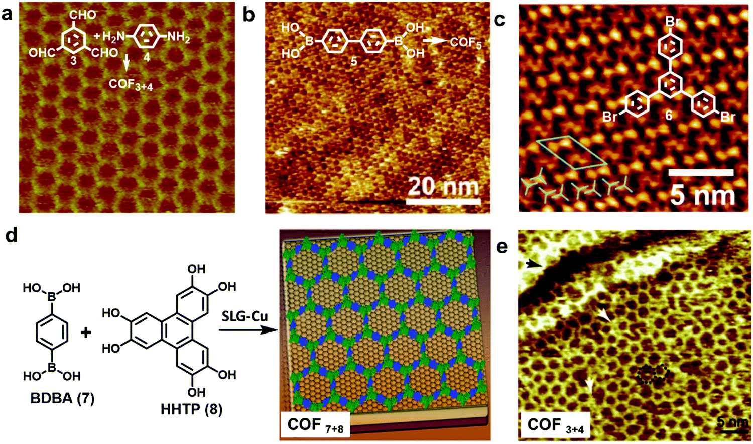 | ||
| Fig. 4 (a–c) High resolution STM images of an imine-linked COF3+4 (a), boroxine-linked COF5 (b), and 1,3,5-tris-(4-bromophenyl)benzene (6) monolayer on a graphite surface (c); (d) the growth of COF7+8 thin films on the SLG-Cu surface; (e) STM image of single layer COF3+4 on the SLG-Cu surface. A “5 + 7” defect is highlighted with a black dotted line and two typical domain boundaries are marked by the white arrows. Reproduced with permission: (a) from ref. 10, Copyright 2013, The American Chemical Society; (b) from ref. 5 Copyright 2012, The American Chemical Society; (c) from ref. 17, Copyright 2013, The Royal Society of Chemistry; (d) from ref. 18, Copyright 2011, AAAS; (e) from ref. 14, Copyright 2013, Wiley. | ||
HOPG has also been used in solid–liquid interface reactions. Lei and coworkers have reported the synthesis of various imine-linked 2D COFs through deposition of a mixture of benzene-1,3,5-tricarbaldehyde and various diamines in octanoic acid followed by their copolymerization at room temperature or under moderate heating.13–15 Lackinger and coworkers reported the polycondensation of various boronic acids to form boroxine linked 2D COFs at a liquid–HOPG interface using heptanoic acid as a deposition solvent (Fig. 4b).5,16 HOPGs have been rarely used as a substrate in coupling reactions, where catalytically active substrates are preferred. It has been reported that 1,3,5-tris-(4-bromophenyl)benzene (6) forms a self-assembled monolayer with long range order on the surface of graphite (001) under high vacuum (UHV) deposition conditions (Fig. 4c).17 However due to the lack of catalytic activity of the graphite surface, annealing of the sample at a high temperature of ∼320 °C for 10 min only resulted in complete desorption of the monomers.
Recent advances in the chemical vapor deposition technique (CVD) have enabled the growth of large area single layer graphene (SLG) on various substrate materials, such as metal surfaces or Si wafers. SLG grown on copper films has been used as a support in the interfacial growth of 2D COFs.14,18 The Dichtel group reported that oriented COF thin films can be formed on the SLG surface supported on Cu foil (SLG/Cu) under solvothermal conditions through the condensation of 1,4-benzenediboronic acid (BDBA, 7) and 2,3,6,7,10,11-hexahydroxytriphenylene (HHTP, 8) (Fig. 4d).18 The COF layers stack along the direction perpendicular to the SLG surface and show an improved crystallinity than the powder form. Later, the SLG/Cu surface was also used to grow single layer COF3+4 by the Lei group (Fig. 4e).14 The STM image shows some “5 + 7” defects and domain boundaries formed due to the incomplete reactions. The authors suggest the presence of strong coupling between the surface COF3+4 layer and graphene, based on the DFT calculations and the observed dependence of STM image contrast on different parts of SLG/Cu and tunneling conditions. The potential advantage of using SLG grown on other thin film surfaces as a support would be the convenient incorporation of such modified surfaces into various devices.
A glass surface is optically transparent, electrically insulating, and cheap, and therefore is highly desirable for the fabrication of various devices, such as optical equipment and semiconductors. Bein and coworkers reported the synthesis of 2D COFs on a glass surface through vapor-assisted co-condensation of diboronic acids and hexahydroxytriphenylene (HHTP).19 A solution of monomers was drop-cast on a clean glass surface, which was then exposed to the vapor of a solvent mixture, mesitylene and dioxane at room temperature for up to 72 h to form a thin layer of polymer films. The thickness of the COF films can be tuned by the deposition amount of the monomers. Cohesive films as thin as 300 nm could be obtained, which contain randomly oriented crystalline COF particles.
2.3 Liquid surface
As previously discussed, formation and immobilization of polymer thin films on solid surfaces provide great convenience for studying their structures through direct imaging techniques, e.g. atomic force microscopy (AFM), transmission electron microscopy (TEM), and STM, with molecular-level resolution. Polymer-grafted solid surfaces can be directly used in the fabrication of advanced nano-scale devices and sensors. Unlike well-defined solid surfaces, the liquid surface is highly flexible and direct observation of structural characteristics of polymer films formed on a liquid surface is challenging. However, liquid surfaces allow the formation of free-standing polymer films, which can be transferred to other desired surfaces for structure characterization or device fabrication. Due to the flexibility of liquid surfaces, the polymer films produced on a liquid surface can be folded, bent, stretched, and compressed. Such high motional freedom of polymer films would be extremely challenging to achieve on a solid surface, if possible at all. Liquid surfaces allow rapid mixing of reactants and high diffusion freedom, thus greatly facilitating chemical reactions that occur at the interface. In theory, the dimensions of polymer films are only limited by the liquid surface size, which can be infinite. Although it is possible to strictly confine polymerization at the interface region of a few molecular layers thick, the precise control of the thickness of polymer films formed at a liquid surface has been challenging.The Langmuir–Blodgett (LB) technique is frequently used to prepare monolayer thick polymer films at the air/water interface (Fig. 5a). Typically, amphiphilic molecules, which consist of both hydrophilic and hydrophobic groups and have good solubility in nonpolar and water-immiscible solvents, are used in the LB method. The solution of amphiphilic molecules in a suitable solvent is spread onto the air/water interface allowing the solvent to evaporate. The deposition amount of the molecules should be low so that the molecules are spread with large intermolecular distances and little lateral interactions. The monomer layer is then slowly compressed, allowing the molecules to self-organize into a compact and well-ordered monolayer film. The changes of surface monolayers during the compression are very similar to the phase changes of three dimensional gaseous, liquid and solid states. Such changes can be monitored by a surface pressure (SP) versus the mean molecular area (MMA) isotherm. After the densely packed monomer layer is formed, polymerization can be initiated to lock the well-ordered structure at the interface. One such representative example is the photopolymerization of anthracene containing monomers through [4+4] cycloaddition using the LB method.20 The amphiphilic monomers were spread at the air/water interface to form a pre-assembled monomer layer. The formation of a homogeneous monomer layer was supported by Brewster angle microscopy (BAM) images. Upon UV irradiation, polymerization occurred and an ordered polymer monolayer was formed. The monolayer was then transferred to the HOPG surface and characterized by STM and nc-AFM, which showed a nanometer thin membrane with a regular array of monodisperse pores of 1.76 to 2.05 nm.
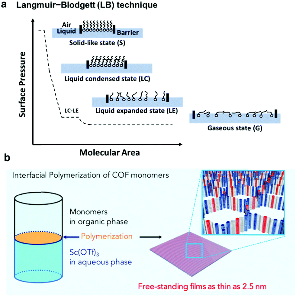 | ||
| Fig. 5 (a) Schematic representation of the Langmuir–Blodgett (LB) technique and the surface pressure (SP) versus the mean molecular area (MMA) isotherm; (b) interfacial imine-condensation polymerization to form a thin free-standing COF film. Reproduced with permission: (b) from ref. 21, Copyright 2018, Cell Press. | ||
Although the LB method provides excellent control over film thickness (monolayer or few layers), it requires amphiphilic monomers and rather advanced instrumentation. As an alternative and more convenient method, COF thin film formation at immiscible liquid interfaces has been developed. As shown in Fig. 5b, crystalline, free-standing COF films could be obtained at the interface between a solution of 1,3,5-tris(4-aminophenyl)benzene and terephthalaldehyde in 1,4-dioxane/mesitylene (4![[thin space (1/6-em)]](https://www.rsc.org/images/entities/char_2009.gif) :1 v/v) and water phase containing a small amount of Sc(OTf)3 catalyst.21 Although both the amine and aldehyde monomers co-exist in the organic layer, the polymerization occurred site-selectively at the interface. The film thickness (100 μm to 2.5 nm) could be controlled by varying the monomer concentrations. A uniform film as thin as 2.5 nm could be obtained. The films could be transferred to carbon grids or silicon wafer substrates for TEM and AFM characterization. The COF film was also able to be transferred to the commercially available PES support to form the COF-PES membrane used for water filtration. This example highlights the great advantage and potential of flexible free-standing COF films formed on the liquid surface, which can be transferred to any arbitrary surfaces for characterization and device applications.
:1 v/v) and water phase containing a small amount of Sc(OTf)3 catalyst.21 Although both the amine and aldehyde monomers co-exist in the organic layer, the polymerization occurred site-selectively at the interface. The film thickness (100 μm to 2.5 nm) could be controlled by varying the monomer concentrations. A uniform film as thin as 2.5 nm could be obtained. The films could be transferred to carbon grids or silicon wafer substrates for TEM and AFM characterization. The COF film was also able to be transferred to the commercially available PES support to form the COF-PES membrane used for water filtration. This example highlights the great advantage and potential of flexible free-standing COF films formed on the liquid surface, which can be transferred to any arbitrary surfaces for characterization and device applications.
While the above liquid–liquid interfacial reaction is convenient, it is hard to obtain monolayer films that are highly desired for certain electronics applications through such method. By combining the convenience of liquid–liquid interfacial reaction and the accuracy of the LB technique, Park and coworkers developed the laminar assembly polymerization (LAP) method, where a polymer film of monolayer thickness grows at a sharp pentane/water interface (Fig. 6).22 In this approach, a solution of the amphiphilic porphyrin tetraaldehyde monomer in a carefully selected solvent was continuously delivered onto the pentane/water interface through a micro syringe pump, which then self-assembled into a monomer monolayer and gradually polymerized with the diamine monomer in the aqueous phase (Fig. 6a and b). The laminar flow of the assembled monomers is critical for the formation of a monolayer polymer film with large-scale continuity and homogeneity in thickness. The polymer monolayer grows unidirectionally along the long sidewalls with little mixing perpendicular to this direction (Fig. 6c and d). The area of the polymer monolayer is proportional to the injected volume of the monomer solution, following a linear relationship (Fig. 6e). Therefore, such LAP approach allows multiple patterning through simultaneous injection of multiple monomers and transferring (Fig. 6f–h). The advantages of the LAP approach include monolayer precision, ambient growth conditions, easy scale up and transferring, and the convenient fabrication of complicated superlattices.
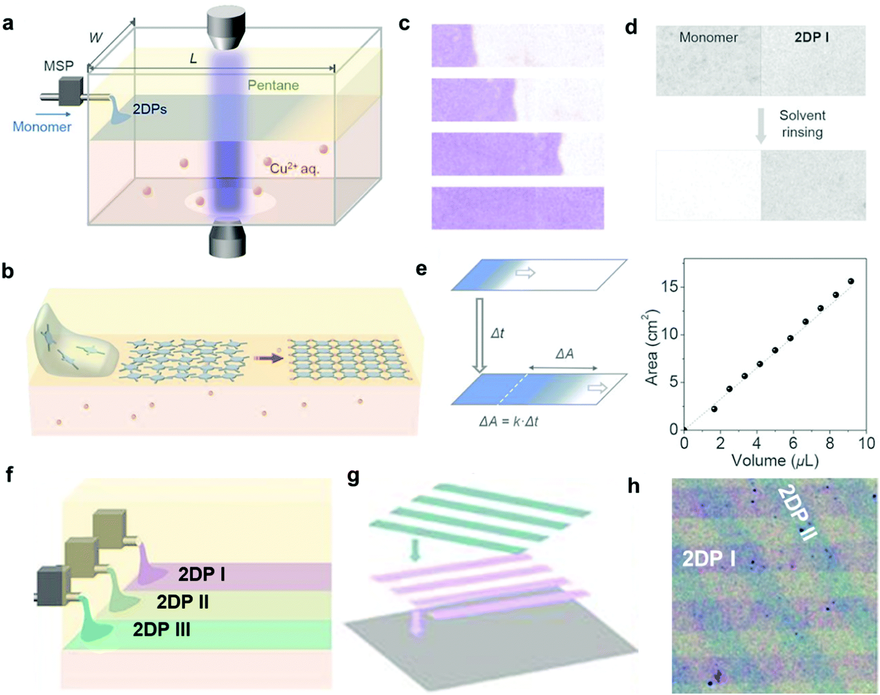 | ||
| Fig. 6 Laminar assembly polymerization: (a) schematic drawing of a LAP reactor and in situ optical characterization apparatus. The sample is injected using a micro-syringe pump (MSP); (b) schematic representation of the LAP synthesis of the polymer monolayer involving three phases; (c) optical images of polymer monolayers at four different stages during the growth. The movement of the assembly is unidirectional, parallel to the longer sidewalls, with a minimal crossover. The film was colored purple; (d) optical transmission images showing that the unreacted monomers can be washed away whereas the polymer monolayer remains intact; (e) the relationship between the film area and the injected volume of the monomer solution; (f–h) schematic representation of fabrication of laterally patterned and vertically stacked hetero-structures using three nozzles in LAP and through multiple patterning and transfer steps. Compositions and widths can be tuned by introducing different monomers at different injection rates. Scale bar: 500 μm. Reproduced with permission from ref. 22, Copyright 2019, AAAS. | ||
3. Building blocks
Although a plethora of 2D COFs have been synthesized in the bulk phase using geometrically well-defined small molecule building blocks that retain their shape during covalent linking and crystallization, on-surface synthesis of 2D COFs has been much less explored with only a limited variety of monomers. In this section, we will discuss monomer design principles (geometric shapes, size, and functional groups), stoichiometry, concentration, and monomer interactions with surfaces.3.1 Geometry requirement
To construct 2D COFs with regular arrangement of molecular building units, we need to create tessellation through repeated arrangements of monomer building blocks. The geometric shapes of monomers are therefore critical as they need to tessellate on a plane by themselves or in combination with other building blocks. If a planar framework with periodicity could be created as a defect-free extending network, the design of monomers must satisfy the critical mathematical requirement of tessellation. Monomers with mismatching geometry for the targeted tessellation patterns would be unable to produce strain-free ordered 2D COFs. There are three types of tessellations, regular tessellations, semiregular tessellations, and non-regular tessellations (Fig. 7). Regular tessellations are formed solely by congruent regular polygons, and semi-regular tessellations are formed by two or more types of regular polygons.23 There are only three regular tessellations and eight semi-regular tessellations, where all the polygons are arranged around vertices in the same order. When the shapes and their arrangement around vertices are not restricted, there are infinite number of non-regular tessellations.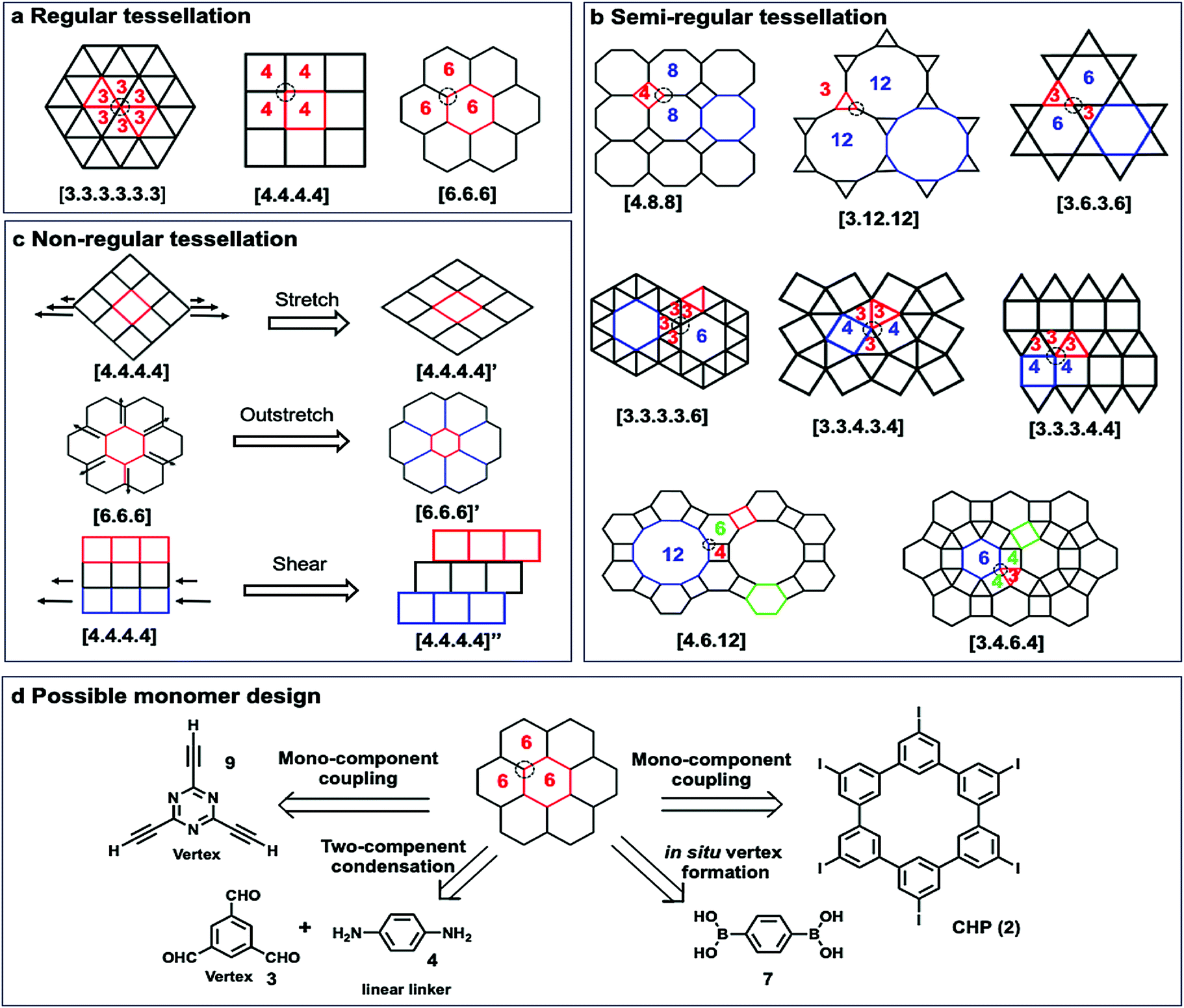 | ||
| Fig. 7 Schematic representation of tessellations and the possible retrosynthesis approach. (a) Regular tessellations; (b) semi-regular tessellations; (c) non-regular tessellations; (d) examples of possible monomer designs to form [6,6,6] tessellations. | ||
The reported 2D COFs are mostly limited to regular tessellated patterns of polygons, such as [3.3.3.3.3.3], [4.4.4.4], and [6.6.6], with only a few exceptions, where semi-regular, e.g. [6.3.6.3], and non-regular tessellations, such as brick-wall [4,4,4]” patterns, are created. For each of the tessellated structures, there are several monomer design options. For example, the most common [6,6,6] tessellation could be constructed by four different approaches: (i) mono-component homo-coupling of tri-functionalized monomers, e.g. 2,4,6-triethynyl-1,3,5-triazine (9), which can serve as vertices; (ii) homo-coupling of hexameric macrocyclic monomers (2); (iii) two-component condensation of a tri-functionalized vertex and a linear linker, e.g. imine condensation of 1,3,5-trifomyl benzene (3) and p-phenylenediamine (4); (iv) in situ formation of vertices, e.g. boroxine formation from BDBA (7).
The shape of 2D COFs is largely determined by the geometrical and chemical information encoded into the building blocks. Generally, rigid monomers with aromatic moieties and a minimum number of saturated carbons in the backbone are used to retain their shape during polymerization and form tessellated polymers. The angle and directionality of reactive functional groups are critical, which determine the angle strain in target structures. Each tessellation requires building blocks with an optimal angle between two functional groups to minimize angle strain and achieve the desired structure as the thermodynamically stable species. Geometrical mismatch between two monomers would cause energy penalty and prevent the formation of ordered tessellations.
3.2 Size of monomers
The rational design principle for the preparation of COFs with predictable structures and properties has been extensively explored using tailorable organic molecular linkers to control their pore size and functionality in the bulk phase. The size of monomers has shown a similar effect on the pore size of COFs formed at an interface. A well-established isoreticular expansion strategy is commonly applied to tune the size of monomers, where the length of an organic spacer group of a monomer is increased by adding conformationally rigid entities, such as phenyl or ethynyl groups, while maintaining the steric arrangement of the linkers. Using such a strategy, Lackinger and co-workers synthesized a series of COFs with the same network topology but different pore sizes (1.0–3.2 nm in diameter) on the graphite surface starting from linear diboronic acids of various lengths (Scheme 1a).5 The Lei group also reported the on-surface isoreticular synthesis of topologically identical 2D COFs through imine condensation of a series of linear diamine linkers with 1,3,5-trifomyl benzene (Scheme 1b).13,24 All of these surface COFs show nearly complete surface coverage and high structural quality based on STM characterization.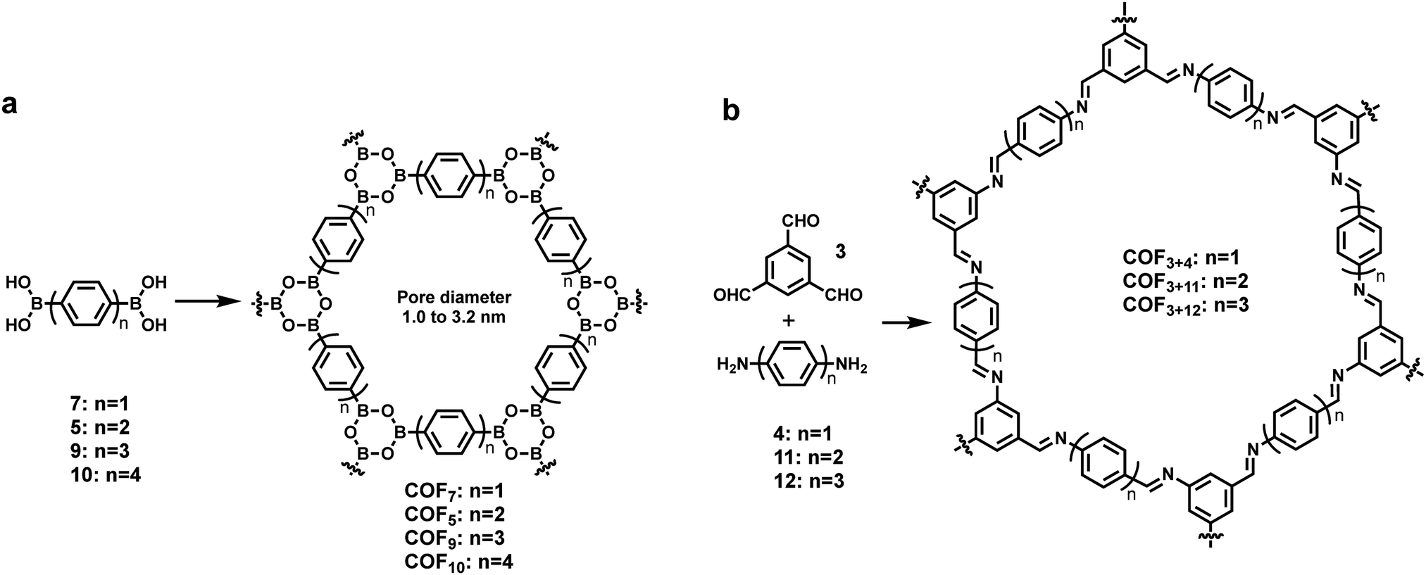 | ||
| Scheme 1 The formation of isoreticular COFs with systematically tuned pore sizes by varying the lengths of building blocks. | ||
In the interfacial synthesis of COFs, monomer sizes not only determine the pore dimensions of the resulting COFs, but also greatly influence the adsorption/desorption and diffusion properties of the absorbed species (monomers or reaction intermediates) on a given surface. Therefore, to obtain ordered COF structures, monomers of different sizes might require different solvents and temperature, both of which have a significant effect on molecule–molecule and molecule–substrate interactions. For example, the thermal activation temperature for self-condensation of diboronic acid monomers increases with the length of monomers. Monomers 7 and 5 start to polymerize on a graphite surface below 50 °C, whereas the longer monomer 9 polymerizes at 70 °C. Monomer 9 forms a self-assembled H-bonded monolayer upon deposition. As the molecular packing density of such monomer monolayers is generally higher than that of their corresponding COF layers formed after dehydration (boroxine formation), desorption and diffusion of monomers are necessary to form covalent monolayers, which requires high activation temperature. In contrast, smaller monomers 7 and 5 directly polymerize without forming such supramolecular networks, likely because of their low adsorption energy and thus lack of stabilization. In another example, Lei demonstrated that COF3+4 can be readily synthesized through imine condensation at room temperature at the octanoic acid/HOPG interface, whereas under the same conditions the reactions between 3 with longer linkers, 11 and 12 provided amorphous polymers. The well-ordered COF3+11 and COF3+12 formed only after the change of the deposition solvent to DMSO and heating at 140 °C under vacuum conditions. The adsorption/desorption and diffusion dynamics of the monomers, and thus the reaction kinetics and thermodynamics, are directly influenced by monomer sizes.
3.3 Reactivity of functional groups
On-surface synthesis of 2D COFs has been accomplished through various types of self-polymerization (one type of monomers) or directional polymerization (two or more types of monomers). Taking advantage of the reactivity difference of functional groups, programmed assembly of 2D COFs can be realized through judicious design of monomers. Previously, a few reports have demonstrated a hierarchical assembly strategy to construct COFs with improved structural order by sequential activation of functional group reactivity. Grill and co-workers reported that by positioning iodide and bromide groups in one monomer and sequentially activating their coupling, a polymer network with a large size of ordered domains can be obtained. A square-shaped porphyrin building block was functionalized with two different types of halogen atoms (I and Br) in trans configuration, encoding two directions of growth. The key to achieve hierarchical sequential coupling is the difference in the bond dissociation energy of Br–Ar (∼336 kJ mol−1) and I–Ar (272 kJ mol−1), which allows stepwise dehalogenation of the iodo sites at low temperature and subsequent activation of the bromo sites at a higher temperature. As shown in Scheme 2, upon heating to 120 °C, one-dimensional polymer chains formed where monomers 1 were connected at the terminal iodo-substituted sites via the selective C–C coupling. In the following step, the remaining bromo-substituted sites were activated, and further inter-chain coupling led to the formation of the interconnected surface polymer. The network synthesized through such a sequential coupling approach shows more ordered structures and larger domain size compared to that obtained using a four bromo-substituted monomer (Br4TPP, 14) by the same procedure through one-step network formation. This example demonstrates that programmed hierarchical growth of 2D COFs is possible if functional groups with different reactivity are logically introduced in the monomer design.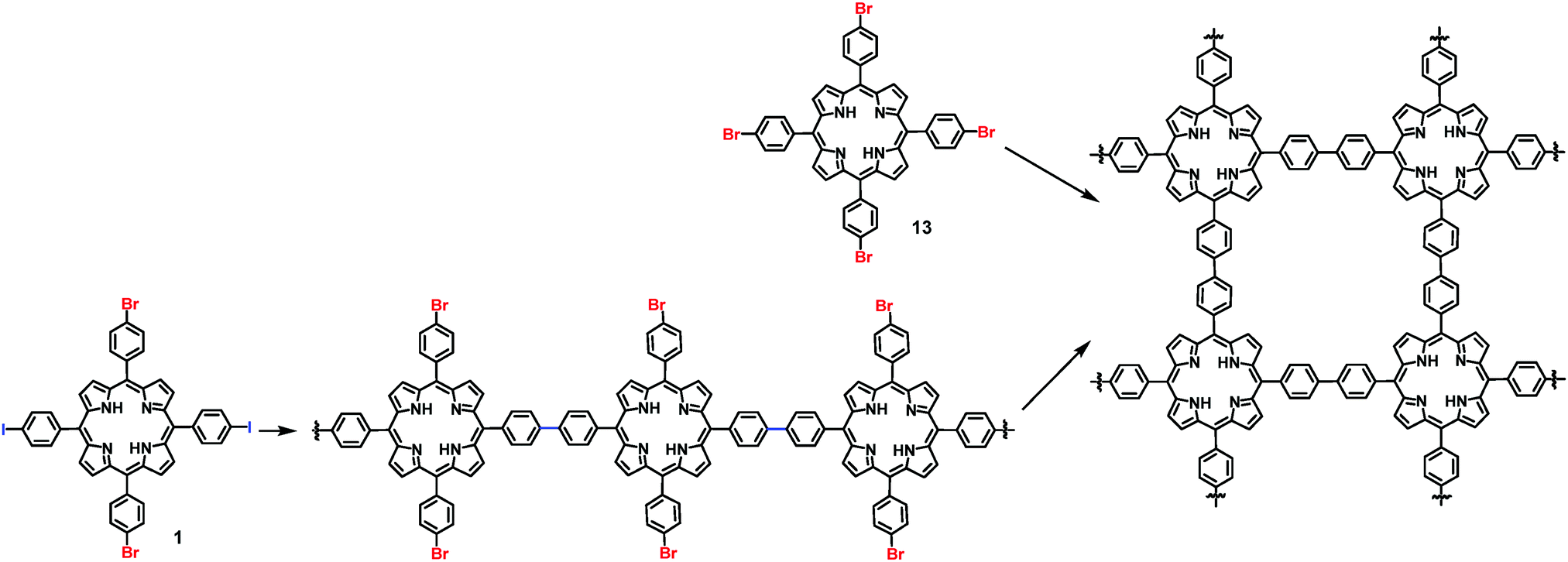 | ||
| Scheme 2 Synthesis of 2D COFs through a sequential coupling approach from monomer 1 and one-step polymerization from monomer 13. | ||
3.4 Stoichiometry of monomers
For multi-component reactions, it has been generally accepted that the right stoichiometry of components is required to form the desired structures. However, for multi-component interfacial reactions, the optimum stoichiometry of building blocks is not always the value which satisfies the critical 1:1 molar ratio of complementary functional groups. It is often more complicated than in the case of solution phase synthesis as the availability of monomers on a surface is also largely determined by molecule–molecule and molecule–substrate interactions. Nevertheless, product compositions are still greatly influenced by stoichiometric ratios of reactants. Different products can be selectively formed by tuning the stoichiometry of reactants, thus enabling the customizable synthesis. The imbalanced monomer ratio could promote the self-organization of oligomers, while the balanced stoichiometric ratio could lead to the growth of ordered surface COFs. Chi and co-workers reported that oligomeric products and COFs can be selectively obtained by simply varying the stoichiometric ratios of the reaction precursors.25 When the stoichiometric ratios of 12 (di-topic linker) and 14 (tri-topic vertex) building blocks are increased from 1:2 to 2:3 and to 3:1, bowtie-, hexagon-, and triangle-shaped structures were formed, respectively, on the Au(111) surface under UHV conditions (Fig. 8a–c), well consistent with the theoretical predictions (Fig. 8d–f). The selective formation of certain products is a result of the balance of the coupling rate of precursors and the mobility of monomers and oligomers on the surface, demonstrating the importance of the stoichiometric ratio during the on-surface reaction.
 | ||
| Fig. 8 (a) Synthesis of imine-linked COF12+14; (b–d) STM images of the condensation products of monomers 14 and 12 in different stoichiometries; (e–g) corresponding Monte Carlo simulations of molecular interactions under different stoichiometries of monomers. The stoichiometric ratios of monomers 14 (blue) and 12 (red) are varied from 2:1 (b and e) to 2:3 (c and f) and 1 : 3 (d and g). Reproduced from ref. 25 with permission, Copyright 2016, The American Chemical Society. | ||
The Wang group also studied the effect of the molar ratio of monomers on the formation of COFs on a surface.26 Interestingly, when the reactive groups were introduced at the 1:1 stoichiometric ratio, only non-covalent assembly of the starting monomers was observed. The target COF structure started to emerge upon increasing the molar ratio of the diamine monomer. As shown in Fig. 9, a large number of rod-shaped structures and small patches of polygonal networks were observed on the HOPG surface at 1:8 molar ratio of monomers 15 and 12. When the ratio was increased to 1:30, co-existence of hexagonal networks with a domain size of around 40 nm2 and some self-assembled monomers was observed on the HOPG surface. The formation of ordered networks with high surface coverage was only observed with a large excess of the diamine monomer (1:50 molar ratio of 15 and 12). Tri-aldehyde monomer 15 has a large planar aromatic backbone and favors the formation of a self-assembled supramolecular monolayer on the HOPG surface. Therefore, the formation of COF15+12 requires extra driving force to compete with such a self-assembly process. Increasing the molar ratio of the diamine monomer increases the chemical potential of the reactant and shifts the reaction equilibrium toward polymerization based on Le Châtelier's principle. Also, the excess diamine monomers provide a basic environment for the transimination reaction, which enables the self-correction mechanism and promotes the formation of highly ordered COFs.
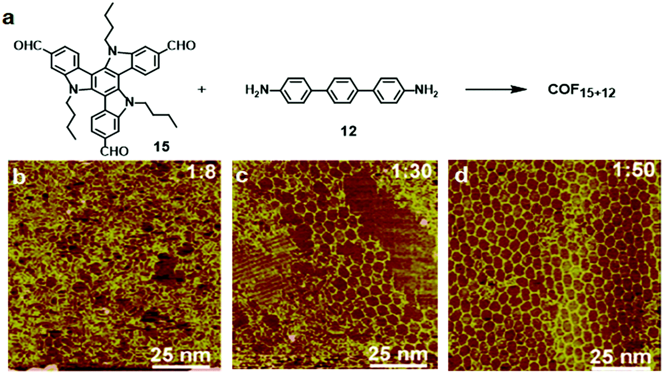 | ||
| Fig. 9 (a) Synthesis of COF15+12 on the HOPG surface through co-condensation of monomers 15 (10−6 M) and 12; (b–d) SEM images of the adlayers formed after heating at 170 °C for 3 h. The molar ratios of 15:12 are 1:8 (a), 1:30 (b), and 1:50 (c). Reproduced with permission from ref. 26, Copyright 2019, The American Chemical Society. | ||
3.5 Concentration
Although the formation of surface COFs with high structural order heavily depends on the thermodynamics of the reactions, kinetics also plays a major role in determining the outcome of such a process. To form an ordered COF with a large defect-free domain, balancing the kinetics and thermodynamics of self-assembly and polymerization is very important. The reversibility of dynamic covalent reactions controls the “error-correction” process during the synthesis, which is crucial for obtaining ordered 2D covalent networks. However, the kinetic parameters, such as adsorption/desorption rates of different species, their mobility on the surface, and nucleation rates, can greatly influence the results of surface reactions. Monomer concentration is one important factor that can be easily tuned to steer reaction kinetics.24,27 It has been reported that by controlling monomer concentration, morphologies of COFs can be modulated at a solid–liquid interface. The change in monomer concentration induces changes in the adsorption–desorption equilibrium, leading to changes in absorbate polymorphs. At high concentrations, high density polymorphs with high adsorption energy per unit area are favored, whereas low monomer concentration favors low density polymorphs. For example, the Wang group reported a concentration dependent formation of a series of surface COFs with rhombus, parallelogram, and Kagome morphologies from the same monomer (Fig. 10a–d).28 When the concentration of the monomer (16) was 1 × 10⁻⁴ mol L−1, two types of quadrate networks (rhombus and parallelogram) were the major products. Conversely, as the monomer concentration decreases (4 × 10⁻⁶ M), another network phase, a Kagome structured morphology, becomes prevalent throughout the surface (e.g. ∼60% coverage vs. 6% at high concentrations in COF16+12) (Fig. 10e). For any pair of monomers, three structures have the same number of covalent bonds after the reaction and therefore roughly have the same chemical free energy. However, the Kagome COF has a smaller network density than the rhombus and parallelogram network (Fig. 10f), and therefore is favored at the lower concentration. It should be noted that the thermodynamics and kinetics of the interface reactions are more complicated than bulk phase synthesis as they involve not only chemical reaction itself but also the simultaneous adsorption–desorption and diffusion of molecules on the surface. | ||
| Fig. 10 (a) Synthesis of imine-linked COFs in three different morphologies; (b–d) STM images of the COFs with rhombus, parallelogram, and Kagome morphologies formed from monomers 16 and 4 on the HOPG surface; (e) concentration-dependent distribution of the three morphological networks: rhombus (cyan), parallelogram (violet), and Kagome (magenta); (f) a table showing number of tetraphenylpyrene-cored units per unit cell (N), unit cell area, and network density of COF16+12 with morphologies. Reproduced from ref. 28 with permission, Copyright 2017, The American Chemical Society. | ||
In liquid/liquid interfacial polymerization, two non-miscible liquids are utilized to create the interface. Monomers are usually dissolved in one phase and catalysts are dissolved in the other. When more than one type of monomers are used, they could be dissolved in two separate phases and the polymerization strictly occurs at the interface. In either case, the concentration of a monomer solution is the critical factor controlling the thickness of polymer layers formed at the interface. Dichtel and co-workers synthesized a series of COF thin films at the liquid/liquid interface via the polymerization of 1,3,5-tris(4-aminophenyl)-benzene (TAPB, 18) and terephthalaldehyde (PDA, 19).21 As expected, the thickness of the COF thin films is highly concentration dependent as shown in Fig. 11b. It can be tuned over several orders of magnitude ranging from 100 μm to 2.5 nm by simply changing the initial monomer concentrations. A similar concentration effect on the thickness of polymer films was also reported by Banerjee and coworkers in the formation of a crystalline imine-linked COF film at the liquid–liquid interface.29
 | ||
| Fig. 11 (a) Synthesis of COF18+19; (b) schematic representation of the interfacial polymerization of monomers 18 (TAPB) and 19 (PDA) at the interface between the organic and aqueous phases, which contain monomers (TAPB and PDA) and Sc(OTf)3 catalyst, respectively; (c) the thickness of COF18+19 films varies over several orders of magnitude depending on the initial concentration of TAPB. Reproduced with permission from ref. 21, Copyright 2018, Cell Press. | ||
4. Types of reactions explored in the synthesis of surface COFs
There are two ways to create ordered framework structures on a surface: (1) pre-assembly of monomers into ordered structures (e.g. supramolecular networks) followed by polymerization by kinetically trapping the preassembled network structures; (2) under thermodynamic equilibrium conditions involving dynamic reversible reactions, where error-correction is enabled through the cleavage and reconnection of dynamic bonds at defect sites. Although it is possible to create ordered surface COFs through irreversible polymerization reactions, many examples have illustrated the benefit of reaction reversibility in creating large-scale ordered structures with minimal defects. In this section, we summarize the reactions that have been used in the synthesis of surface COFs.4.1 Irreversible polymerization reactions
Various irreversible reactions have been explored to prepare 2D polymers at interfaces (Scheme 3), which can be categorized into three main types: (1) various coupling reactions, including Glaser coupling, Ullmann coupling, decarboxylative homocoupling, and Suzuki coupling. The former three coupling reactions are self-coupling reactions that require only one type of monomers. By contrast, Suzuki coupling requires two types of monomers containing complementary functional groups. (2) Various cyclization reactions, including cyclotrimerization of acetyls,30 cyclotetramerization of phenylnitriles,31 and [4+4] photocyclization,20 all of which require only one type of monomers. (3) Imide formation through condensation of an amine and an anhydride. | ||
| Scheme 3 Irreversible reactions used in the synthesis of surface 2D COFs. | ||
Since all of these reactions are inherently irreversible, once new bonds are formed, the connection between two monomers becomes permanent. Therefore, preassembly of monomers into packing geometries that closely resemble those of desired polymer networks is critical to form ordered polymer networks. In solid surfaces, it has been commonly observed that molecules self-assemble into ordered supramolecular networks through non-covalent forces such as hydrogen bonds and van der Waals interactions. However, in many cases, monomers form densely packed networks, which require significant desorption, diffusion, and rearrangement in order to form porous 2D COFs that often have much lower monomer packing density. Thermal annealing is generally performed to initiate polymerization and induce the necessary adsorption/desorption and diffusion dynamics that are required for the network structure reorganization. However, limited success has been achieved through such an approach on a solid surface as the increase of temperature also causes significant desorption of monomers. For example, the STM images in Fig. 12 show that 1,3,5-tris(4-acetylphenyl)benzene (20) forms a densely packed pinwheel assembly structure after initial deposition on the Ag(111) surface at room temperature, which is stabilized by the hydrogen bonding between the O atom of the acetyl and the phenyl ring.30 However, direct thermal annealing of such a monomer network led to molecular desorption and low surface coverage. Deposition of the molecules at an elevated temperature prevents the pre-formation of monomer assembly networks and leads to direct polymerization. However, limited improvement was achieved, showing low surface coverage (Fig. 12b). Similar phenomena were also observed for the decarboxylative homocoupling of 1,3,5-tris(4-carboxyphenyl)-benzene (21) on Cu(111).32 The precursor molecule forms a self-assembled trigonal structure stabilized by hydrogen bonding interactions with a good surface coverage and high monomer density on Cu(111). Thermal annealing at 180 °C for 15 min activates the polymerization of the monomers through decarboxylative coupling. However, consistently irregular networks with very low surface coverage were obtained. In both examples, the monomers form ordered supramolecular networks, whose structures are not relevant to the desired porous COFs and need substantial rearrangement to form porous COFs.
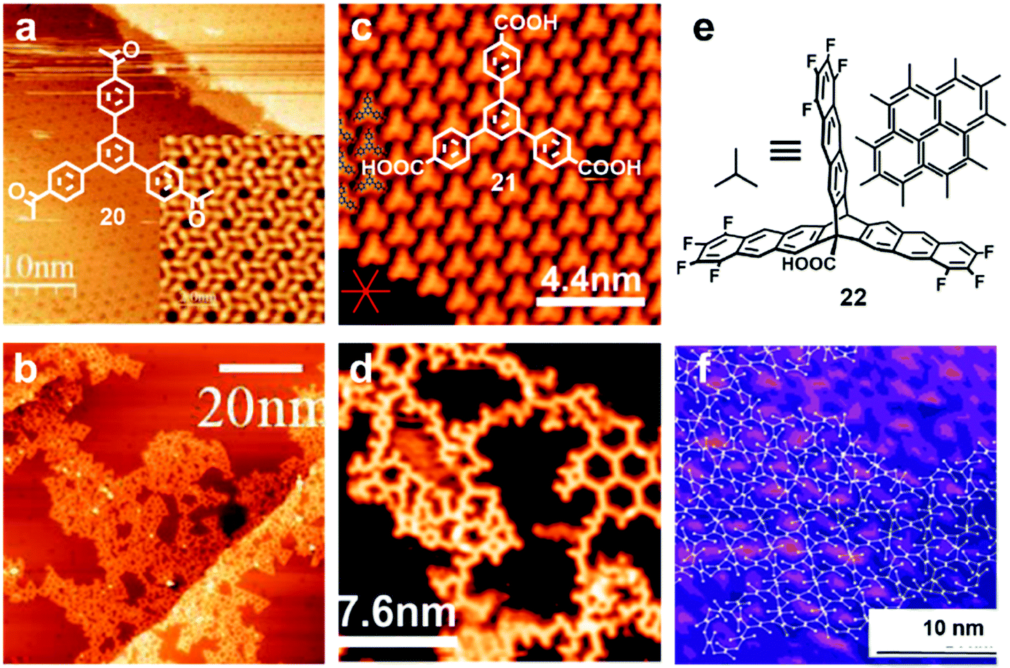 | ||
| Fig. 12 (a and b) STM images of the supramolecular network of monomer 20 formed after room-temperature deposition (a), and the polymer network formed after the deposition with the substrate held at 590 K; (c and d) STM images of the self-assembled monolayer of monomer 21 on Cu(111) after deposition at room temperature, and covalent network structures obtained after annealing at 220 °C for 15 min; (e and f) the chemical structure of anthracene containing monomer 22 and the schematic representation of their possible packing on the surface (e) and STM image of the polymer with long range order (f). Reproduced with permission: images (a and b) from ref. 30, Copyright 2015, the American Chemical Society; images (c and d) from ref. 32, Copyright 2016, The American Chemical Society; images (e and f) from ref. 20, Copyright 2017, Wiley. | ||
When monomers are designed to pack in similar conformations as the desired polymer networks prior to the polymerization, large-scale well-ordered covalent monolayers could be obtained upon irreversible polymerization. One such example has been demonstrated by Schlüter and coworkers at the air/liquid interface.20 The anthracene containing monomer 22 was designed to orient and pack in a face-to-face antiparallel fashion (Fig. 12e) through favorable dipole–dipole and quadrupole interactions between the electron-rich and the electron-poor parts of the tetrafluoroanthracene moieties and amphiphilic interactions with the water surface. Such monomer packing closely resembles the monomer orientation in the targeted polymer network, and thus requires minimum structural rearrangement during their polymerization. Upon UV irradiation, [4+4] cycloadditions between neighboring anthracenes occur to form the ordered porous 2D COF. The image of a large scale 2D COF structure with a regular hexagonal lattice could be clearly visualized under STM (Fig. 12f) and nc-AFM using a higher eigenmode as well as multipass imaging techniques. The polymer monolayer extends over the entire area of 120 × 120 nm2, showing a regular array of monodisperse pores. This is the largest monolayer polymer network with structural orderliness reported to date. Although the polymerization step is irreversible, only some minor defects were observed, suggesting that the monomer preassembly already has a high degree of long-range order. However, due to the dynamic nature of the water surface and supramolecular assemblies, the direct observation of such monomer packing on the surface was not possible through common imaging techniques. Nevertheless, controlling the organization of monomers is critical for achieving long range order in surface COF formation, when self-correction is not permitted.
Most of the surface 2D COF syntheses through irreversible polymerization use a single type of monomers. However, a couple of systems comprise more than one monomer, e.g. Suzuki coupling reactions and imide formation. In general, the molecular assembly of two components on a surface is more complicated and challenging than that involving a single component. The Suzuki polymerization of (1,4-bis(4,4,5,5-tetramethyl-1,3,2-dioxaborolan-2-yl)benzene) and 1,3,5-triiodobenzene at a water–toluene interface in a refrigerator was reported.33 A 2D COF film with large lateral size, crystalline order, and a thickness of 18 nm was obtained. However, the extent of defect formation and the size of continuous ordered domains are unclear. Very recently, the controlled synthesis of two-dimensional polyimide through the reaction between two components, porphyrin tetraamine and anhydride monomers, was reported.34 Imide polymers with high crystallinity and a thickness of ∼2 nm were obtained with an average crystal domain size of ∼3.5 μm2. The formation of crystalline polymers is largely attributed to the pre-organization of monomers with the aid of a surfactant bearing a carboxylic acid group. This report reveals the critical importance of preorganization of monomers in the desired orientation to obtain ordered polymer structures.
To minimize the structural defects caused by the irreversible covalent bond formation, the sequential coupling approach with programmed functional group reactivity was developed by some groups. For example, as previously mentioned, hierarchical sequential Ullmann coupling was developed by taking advantage of different activation barriers of deiodination and debromination on the Au(111) surface. The activation of trans-Br2I2 tetraphenyl porphyrin at relatively low temperatures (120 °C) selectively initiates the coupling of phenyl-iodine sites to form linear polymer chains. These 1D linkages arrange in a parallel manner on the anisotropic corrugated gold surface. Subsequent activation of phenyl-bromine coupling connects the 1D polymer chains into 2D COF networks with lager domain size, low defect densities, and an overall improved structural quality compared to the direct polymerization of analogous tetrabromo substituted porphyrin monomers.7 A similar sequential polymerization approach has also been investigated by Lackinger35 and Lin36 groups. Here, the hierarchical assembly method through programed reactivity proved to be an effective method to minimize structural defects and increase domain size using an irreversible polymerization approach.
4.2 Reversible polymerization reactions
Dynamic covalent chemistry has been well-recognized as a powerful tool in the thermodynamically controlled self-assembly process.2 When reversible covalent reactions are employed in a system, the interactions between molecules become dynamic, similar to supramolecular chemistry, but through the reversible formation and breaking of strong covalent bonds rather than weak non-covalent interactions. Although various dynamic covalent reactions are available, including the well-known olefin and alkyne metathesis, only three types of dynamic condensation reactions have been explored in the synthesis of COFs at an interface, namely boronic acid self-condensation to form boroxines, boronic acid–diol condensation to form boronic esters, and imine condensation (Scheme 4). The great advantage of these dynamic covalent reactions is their error correction capability, thus enabling the formation of 2D COFs with a long-range order. | ||
| Scheme 4 Dynamic covalent reactions explored in the synthesis of COFs on a surface. | ||
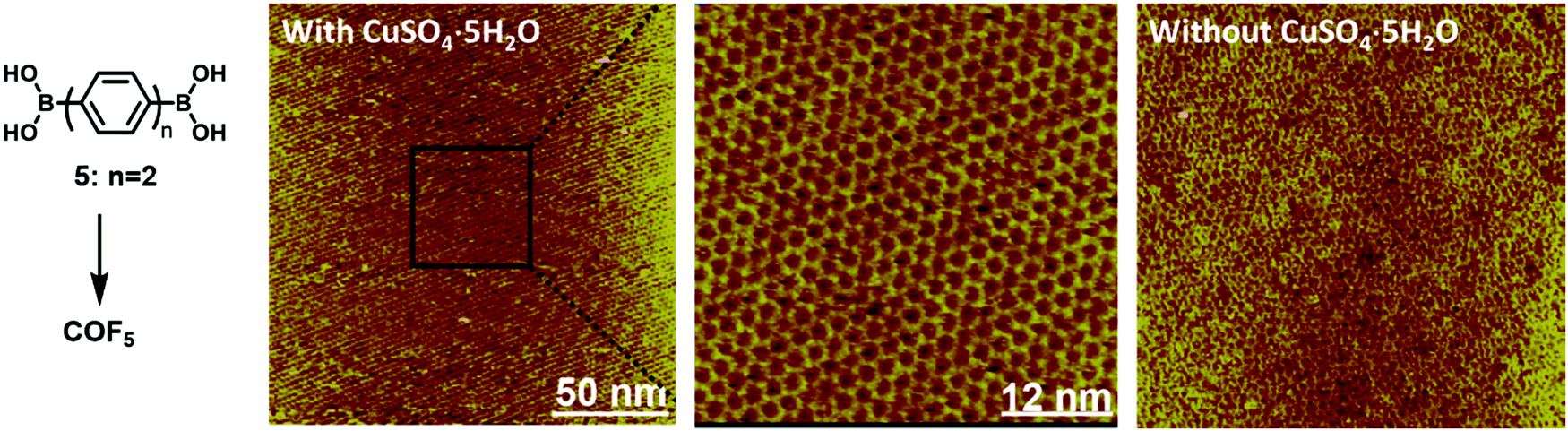 | ||
| Fig. 13 The comparison of STM images of large scale COF5 on the HOPG surface formed through dehydration of monomer 5 at 150 °C in the presence and absence of CuSO4·5H2O. The zoom-in view is also provided to show the high-ordered structure of the COF with very few defect sites. The images were reproduced from ref. 38 with permission, Copyright 2012, The Royal Society of Chemistry. | ||
The reversibility of boronic acid self-condensation on a surface is also highly dependent on the surrounding solvents, which have a dramatic effect on molecule–surface and molecule–molecule interactions. As mentioned previously, processes that occur at the interface include adsorption and desorption of molecules along with their corresponding diffusion across the surface. Therefore, at the liquid/solid interface, the type of solvents greatly influences the error correction process and thus the structure of a monolayer. For example, heptanoic acid facilitates the conversion of the supramolecular network of terphenyldiboronic acid (9) into the boroxine-linked COF under thermal treatment (120 °C) on a HOPG surface in the presence of water, whereas under similar conditions using dodecane as a solvent only partial conversion to an ordered COF was observed. The formation of the COF involves reorganization of the self-assembled monomer monolayer through desorption, diffusion, and redistribution of monomers as the monomer packing density in the COF is 1.4 times lower than that in the supramolecular network. Heptanoic acid is a polar and protic solvent with better solvating ability of diboronic acid monomers and water molecules, whereas dodecane is a nonpolar, aprotic solvent, which has poor affinity toward the monomer as well as water. As a result, the error correction process involving desorption, re-adsorption and redistribution of monomers is greatly facilitated in heptanoic acid, but not in dodecane.
Although reversible formation of boroxines is commonly activated thermally, it has been reported that an electron beam or electric field produced from the tip of a scanning tunneling microscope can also facilitate the boronic acid self-condensation reaction.39,40 De Feyter and coworkers reported interesting electric field-assisted reversible transformation between a boroxine linked COF and the corresponding supramolecular network formed after hydrolysis. As shown in Fig. 14, the reversibility of boroxine formation and hydrolysis can be triggered locally at room temperature through the manipulation of the electric field generated by a STM tip. An oriented electric field was generated by changing the polarity of the applied bias, which selectively activates the polymerization or depolymerization at an octanoic acid solution–HOPG interface, thus achieving phase-transition between the COF and the supramolecular network. The use of 1-octanoic acid as a solvent is critical for the same reason as previously described. No phase transition was observed when 1-phenyloctane was used as the solvent.
 | ||
| Fig. 14 Schematic illustration of the electric-field-induced reversible transformation between self-assembled molecular networks and covalent organic frameworks. The image is reproduced from ref. 40 with permission, Copyright 2019, The American Chemical Society. | ||
When imine condensation proceeds at a solid–vapor interface, the presence of water molecules and sequential deposition of two types of monomers can enhance the structural order of the resulting COFs. Wan and coworkers demonstrated a self-limiting vapor interface reaction strategy to prepare highly ordered imine-linked COFs, where one monomer (18) is preloaded and then the second monomer (19) is introduced as a vapor (Fig. 15).10 Large-scale 2D COF18+19 with rare defects was obtained with typical domain size larger than 350 × 350 nm2, which represents one of the largest monolayer ordered surface COFs prepared on a solid surface. Such a sequential deposition method of two monomers effectively inhibits the rapid nucleation of a large amount of oligomers with restricted mobility on the surface, which commonly occurs when two monomers are premixed prior to the deposition. The growth of ordered COFs can be attributed to the presence of water molecules, elevated temperature, and the deposition order of two monomers. Under optimum conditions, the diffusion of the preloaded monomer and the evaporation of the second monomer reach a critical balance, where the large excess of the preloaded monomer slowly reacts with the limited supply of the second monomer in the vapor phase at the solid–vapor interface to achieve the self-limiting growth of ordered 2D COFs with the error correction mechanism. For such solid–vapor interface reaction, the stoichiometric ratio of precursors is not strictly required. The limitation of this method is the vaporization capability of monomers. The second monomer should be able to vaporize at a reasonably low temperature and have lower vaporization temperature and higher vapor pressure than the pre-deposited monomer.
 | ||
| Fig. 15 (a and b) Synthesis of COF18+19 at the solid–vapor interface through vapor-reaction; (c) large-scale STM image (100 × 100 nm2) of COF18+19 with the inset depicting the corresponding FFT spectrum of the STM image; (d) high resolution STM image (20 × 20 nm2) of COF18+19. Reproduced from ref. 10 with permission, Copyright 2013, The American Chemical Society. | ||
Although imines have been frequently reported to easily hydrolyze, imine-linked 2D networks are highly stable and resistant to hydrolysis on a water surface. Zhang and coworkers reported that a monolayer of imine-linked 2D polymer can be formed at the air–water interface through the acid-catalyzed reaction of an aromatic triamine and a dialdehyde. Corresponding monolayers of imine polymer are very robust and can be transferred to various substrates (silicon wafers, TEM grids) for characterization purposes. The monolayer is stable under electron-beam irradiation and does not decompose immediately when the beam is focused.42 Multilayer imine-linked COFs have also been prepared at immiscible organic solvent–water interfaces mostly in the presence of acid catalysts, such as acetic acid, trifluoroacetic acid, or Sc(OTf)3, in the water phase.21,29,43 Although crystalline features of thin films of surface COFs have been confirmed, the analysis of defect distribution at the molecular level is unavailable. Nevertheless, these results suggest the high resistance of imine-linked polymers against hydrolysis and indicate great robustness and stability of such thin films.
4.3 Orthogonal reactions
Thus far, a single chemical reaction is usually employed to form most of the COF architectures. When two chemical reactions are mutually compatible, they can be defined as orthogonal reactions. Orthogonal reactions combine two or more reactions in one system and offer a tantalizing route towards the preparation of complex systems and structures. However, the scope of such a method remains in its infancy and only a few examples have been explored. Orthogonal boroxine formation and Ullmann coupling have been explored using a monomer substituted with boronic acid and bromide groups.44 As shown in Fig. 16a–c, the doubly functionalized monomer, 4-bromophenylboronic acid, can undergo self-condensation to form boroxine-linked trimers at room temperature, which self-assemble into a densely packed supramolecular network on an Au(111) surface under UHV. Subsequent high temperature (250 °C) thermal annealing activates Ullmann coupling between phenyl bromides to form a covalently linked network. The potential advantage of such an orthogonal reaction approach is the possibility of creating long-range crystalline networks by in situ formation of ordered nanostructures prior to overall COF generation.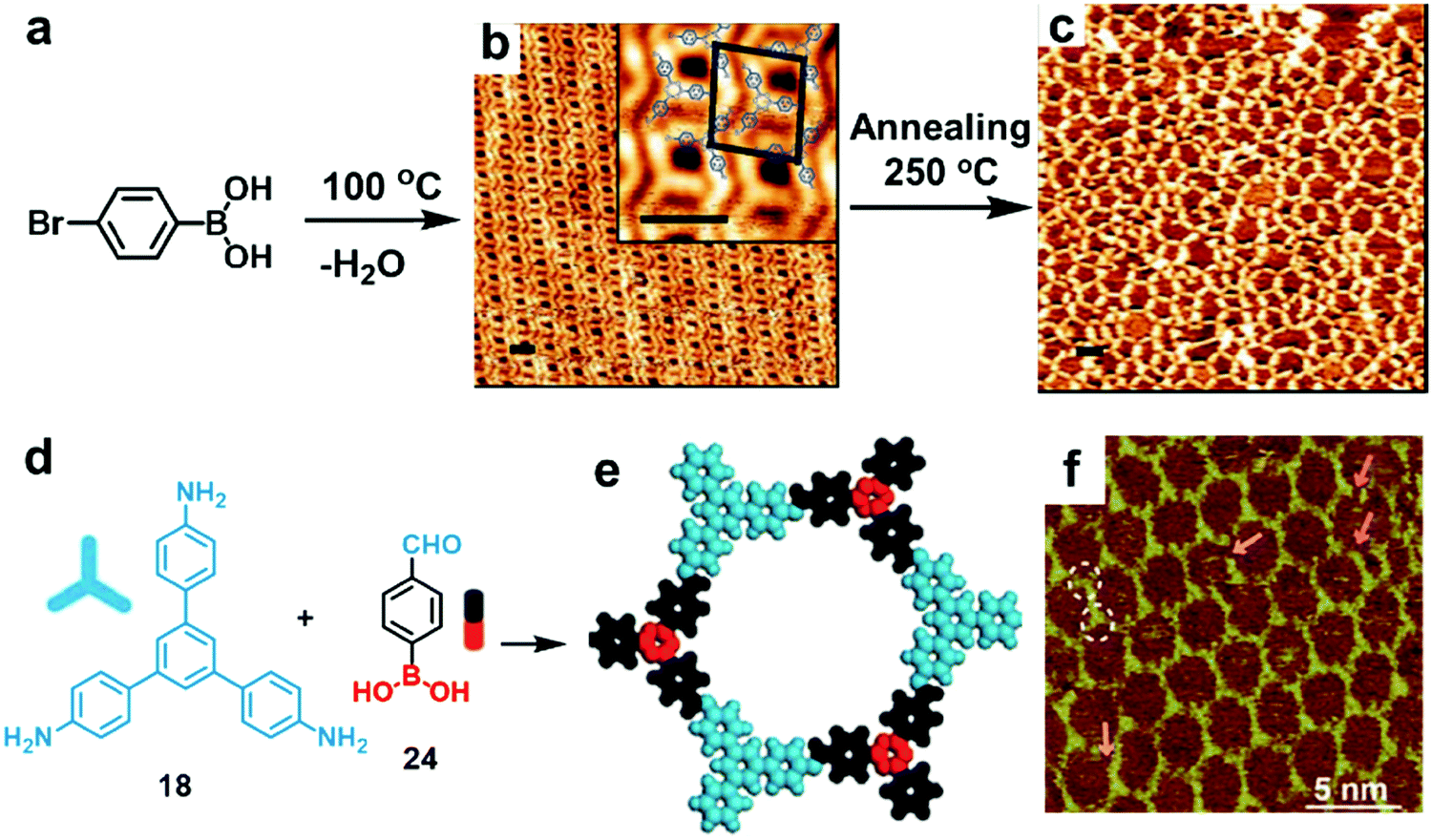 | ||
| Fig. 16 STM images showing sequential formation of covalent networks. (a–c) Orthogonal boroxine formation and coupling of 4-bromophenylboronic acid (BPBA): (a) reaction scheme; (b and c) STM images of densely packed covalent trimers formed through self-condensation of BPBA at room temperature on a Au(111) surface (b) and subsequently formed covalent network through Ullmann coupling after annealing at 250 °C (c) (scale bars in b and c are 2.0 nm); (d–f) the formation of imine-boroxine hybrid COF18+24 from monomers 18 and 24 containing three types of functional groups: (d) reaction scheme; (e) modeling of the hexagonal pore structure; (f) STM image of COF18+24 on the HOPG surface. Reproduced with permission: (b and c) from ref. 45, Copyright 2012, the American Chemical Society; (e and f) from ref. 46 Copyright 2017, The Royal Society of Chemistry. | ||
Orthogonal imine condensation and boroxine formation were explored by Wang et al. to prepare imine–boroxine hybrid COFs at a solid–vapor interface (Fig. 16d–f). The 1,3,5-tris(4-aminophenyl)benzene (18) monomer was pre-deposited on a HOPG surface and bifunctional monomer 24 was introduced as a vapor in the presence of CuSO4·5H2O powder. After thermal treatment in a closed autoclave for 3 h at 120 °C, the HOPG surface was almost fully covered with honeycomb networks, consisting of alternating aromatic rings and boroxine rings. It is not entirely clear how the two monomers react through the orthogonal reactions and how the two reactions proceed (simultaneously or sequentially). The typical domain size of more than 80 × 80 nm2 was obtained with few defects, indicating excellent error correction capability of such a method. Since both imine condensation and boroxine condensation are reversible, COF18+24 formed through such orthogonal reactions has much higher structural order compared to the COF formed through orthogonal reversible boroxine formation and irreversible Ullmann coupling. The use of orthogonal reactions can expand the structural and functional diversity of surface COFs by allowing the possibility of in situ formation of large size monomers and incorporation of multiple functional groups in one repeating unit.
5. Characterization of interface-assisted COF thin films and covalent monolayers
The synthesis and characterization of interface-assisted COF thin films and covalent monolayers represent one of the most rapidly developing areas in 2D materials research. These materials undoubtedly have shown great potential in a variety of applications. The following section will discuss various characterization methods, which can be classified into three different categories, targeting the materials’ (1) chemical bonding, (2) morphology, and (3) crystallinity information.5.1 Characterization of chemical bonding
However, both IR spectroscopy and Raman spectroscopy are limited to the characterization of bulk materials due to the diffraction limit of light. When coupled with the Scanning Probe Microscopy (SPM) technique, they could simultaneously provide topographic and label-free identification of the local chemical environment. Tip enhanced Raman scattering (TERS) is such a technique that combines Raman spectroscopy with high spatial resolution of SPM, enabling the identification of specific chemical components and their distribution at the nanometer scale. The metallic tip used in TERS is the same as the one used for scanning tunneling microscopy (STM) or the metal coated atomic force microscopy (AFM) tip. A strong local electromagnetic field is confined tightly at the tip of the probe, which allows local excitation of surface plasmons by the incident laser, effectively enhancing the Raman scattering signatures. TERS can provide insightful information on chemical bonds and molecular orientation in a covalent monolayer. TERS, therefore, can also be utilized to image the topography and integrity of a monolayer, providing the possibility of mapping nanodefects in monolayer structures. As shown in Fig. 17, a monolayer COF25+26 was synthesized at the air/water interface using a Langmuir–Blodgett (LB) trough from a triamine monomer 25 and a dialdehyde building block 26 containing an acetylene unit. The Raman signal intensity of acetylene groups is known to be particularly angle sensitive when the monolayer is adsorbed on a metal surface. Based on the theoretical calculation, the band at around 2200 cm−1 (C![[triple bond, length as m-dash]](https://www.rsc.org/images/entities/char_e002.gif) C stretching vibration) should be absent when the CC bond is lying flat on the Au(111) surface. Thus, TERS images can clearly distinguish the molecular orientation of the triple bonds in a regular monolayer sheet, a broken sheet, or a simple monomer. The map in Fig. 17b of the as-synthesized COF25+26 monolayer shows a homogeneous S/N distribution at 2220 cm−1, with only ∼2% pixels (red) having S/N ≥ 3, indicating that only very few triple bonds are not parallel to the substrate. In contrast, the broken sheet and the monomer sample show more red pixels indicating that they contain more triple bonds tilted away from the plane of the 2D network (Fig. 17b–d).
C stretching vibration) should be absent when the CC bond is lying flat on the Au(111) surface. Thus, TERS images can clearly distinguish the molecular orientation of the triple bonds in a regular monolayer sheet, a broken sheet, or a simple monomer. The map in Fig. 17b of the as-synthesized COF25+26 monolayer shows a homogeneous S/N distribution at 2220 cm−1, with only ∼2% pixels (red) having S/N ≥ 3, indicating that only very few triple bonds are not parallel to the substrate. In contrast, the broken sheet and the monomer sample show more red pixels indicating that they contain more triple bonds tilted away from the plane of the 2D network (Fig. 17b–d).
 | ||
| Fig. 17 (a) The synthesis of COF25+26; (b–d) TERS signal-to-noise ratio (S/N) maps (100 × 100 nm2, 32 × 32 pixels) at 2220 cm−1 (triple bond signal) within the intact sheet (b), broken sheet (c) and monomer mixture (d); (e) representative TERS spectra obtained from different maps. Reproduced with permission from ref. 47, Copyright 2018, The American Chemical Society. | ||
 | ||
| Fig. 18 (a) Schematic representation of the synthesis of COF27; (b) UV-Vis spectra of the monomer TEPE (27) and 2DP-TEPE (COF27); (c) solid-state fluorescence spectra of the monomer TEPE (27) and 2DP-TEPE (COF27). The inset is the fluorescence optical microscope images of the monomer TEPE and 2DP-TEPE. Reproduced with permission from ref. 48. Copyright 2019, Wiley. | ||
 | ||
| Fig. 19 (a) Synthesis of COF21; (b and c) XPS spectra of the C 1s core level obtained after deposition of the monolayer monomer at RT (b) and after annealing at 220 °C (c); (d) UPS spectra of multilayer monomer 21 deposited on Cu(111) at RT (blue) and after annealing at 220 °C for 15 min (red); (e) STM topography of COF21; (f) STS map containing 30 dI/dV spectra recorded across a polymer and a deprotonated monomer along the cyan line in (e) (Ubias = −1.5 V, I = 0.2 nA, T = 20 K). Reproduced with permission from ref. 32, Copyright 2016, The American Chemical Society. | ||
5.2 Morphology characterization
Noncontact-AFM (NC-AFM) operates based on a similar mechanism; however the tip of the instrument does not contact the sample surface. It measures surface topology by utilizing an attractive force between the tip and the sample surface. A piezoelectric modulator is used to obtain the surface information by keeping a minimum distance between the tip and the sample surface via weak van der Waals interaction. NC-AFM offers the possibility to visualize internal bond structures of a molecule and characterize molecules with comparable submolecular resolution to scanning tunneling microscopy (STM), the most well-established method that has allowed visualization of submolecular features for years. NC-AFM is a rapidly emerging technique and can provide complementary information to the conventional STM technique, which is only capable of viewing the electronic structure of molecules rather than real atomic geometry. In 2018, the Schlüter group for the first time reported the NC-AFM images of a 2D polymer monolayer synthesized at the air/water interface through [4+4] cycloaddition reaction of monomer 22 (Fig. 20a).20 Although a topography image acquired on a polymerized monolayer using the second eigenmode of the sensing cantilever is hard to visualize the molecular structures (Fig. 20b), after applying a special multi-pass technique, where each line was scanned twice, a high resolution image with molecular-level structural information was successfully obtained (Fig. 20c). These images clearly reveal a regular honeycomb structure of the covalent monolayer, which extends over the entire area of 120 × 120 nm2.
 | ||
| Fig. 20 (a) Monomer 22 and the proposed packing; (b) nc-AFM topography image of a 120 × 120 nm2 area; (c) corresponding second pass frequency shift image acquired with the multipass technique. Reproduced with permission from ref. 20, Copyright 2018, Wiley. | ||
5.3 Crystallinity characterization
 | ||
| Fig. 21 (a) Schematic illustration of the synthesis of COF28+29; (b) AC-HRTEM image of COF28+29. Inset: A simulated image of COF28+29 along the [001] projection with the structure model overlaid; (c) SAED pattern. The arrows indicate the 100 and 010 reflections at 0.33 nm−1. Reproduced with permission from ref. 34 Copyright 2019, Springer Nature. | ||
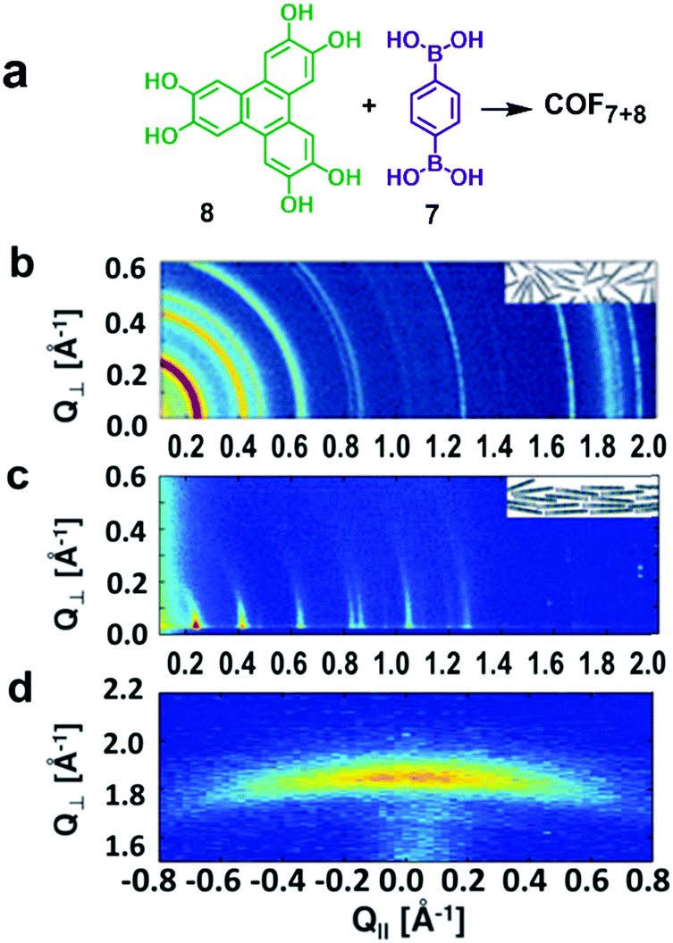 | ||
| Fig. 22 (a) Synthesis of COF7+8; (b) X-ray scattering data obtained from the COF7+8 powder; (inset) schematic of randomly oriented COF7+8 grains in the powder; (c) GID data of a COF7+8 film on SLG/Cu, (inset) schematic of oriented COF7+8 grains in the film; (d) GID data obtained at large Q⊥, showing an off-specular projection of the COF7+8 film (001) Bragg peak. Reproduced with permission from ref. 18, Copyright 2011, AAAS. | ||
6. Examples of COF membranes and covalent monolayers grown at the interface and their applications
As a still growing field in chemistry and materials science, connections between the COF membrane (or covalent monolayer) synthesis and device fabrication are rare, but still highly valuable. In this section, some selective examples of COF thin films/membranes or covalent monolayers that were prepared through interfacial polymerization will be discussed, with a particular focus on their interesting physical properties and great potential in various applications.6.1 COFs formed at the air–water interface
The advantage of air–water interface polymerization is the possibility to get free-standing thin films or even atomic-thin covalent monolayers using amphiphilic monomers with poor solubility in water. Hydrophilic molecules, particularly those that can be dissolved in water (even just a small amount), usually cannot be used in such an approach, which represents a potential drawback. The obtained thin films have to be transferred to other substrates for property study or application, which might cause film/membrane damage during the transfer process.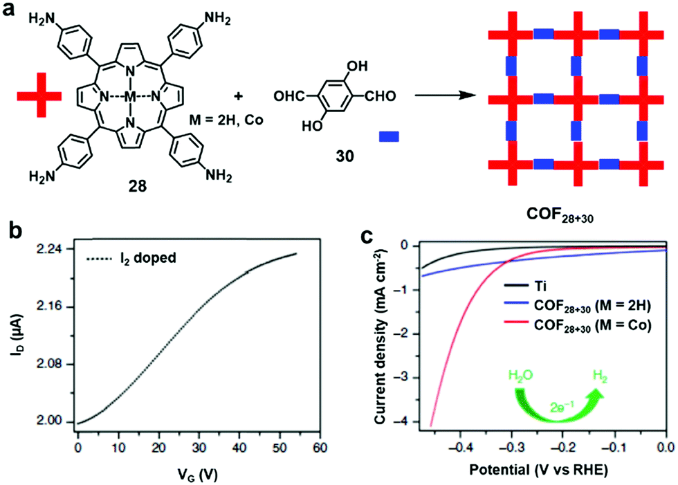 | ||
| Fig. 23 (a) Synthesis of COF28+30 from monomers 28 and 30; (b) transfer curve of a thin film transistor employing COF28+30 (M = 2H) as an active semiconducting layer at a source to drain voltage of −40 V after doping with iodine; (c) hydrogen evolution reaction polarization plots of blank titanium foil (black) and multilayer COF28+30 (M = CoII). Reproduced from ref. 43. | ||
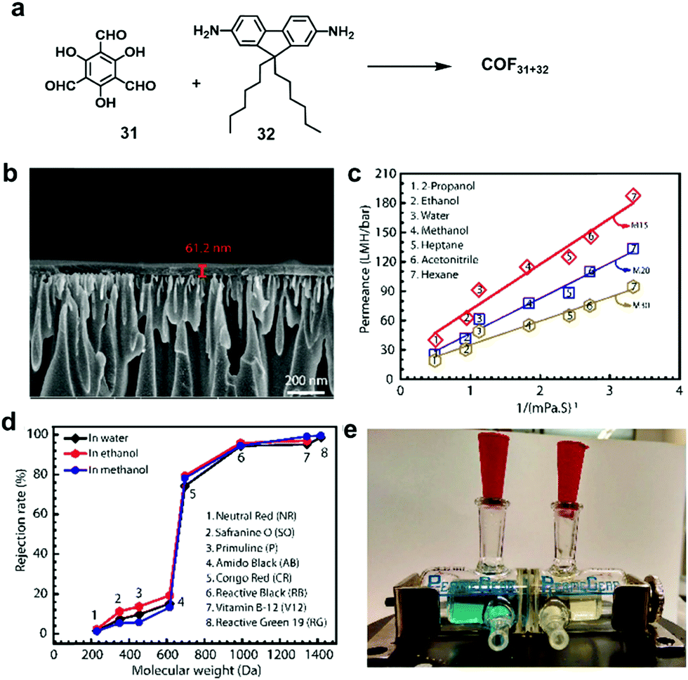 | ||
| Fig. 24 (a) Synthesis of COF31+32 at the air–water interface. (b) Cross-section SEM image of the COF31+32 membrane (20 layers) supported on AAO. (c) Permeances of water and a number of polar and nonpolar organic solvents through the three COF31+32 membranes with 15 (M15), 20 (M20), and 30 (M30) layers, plotted with the inverse of their viscosity. (d) Rejection rates of various dyes through the M20 membrane vs. their molecular weight. (e) Image showing the separation of the mixture of dyes Reactive Green (RG) and Primuline (P). The chamber on the left-hand side contains the mixture of the two dyes, whereas the chamber on the right-hand side is filled with fresh water initially and it turned yellow after 1 day of diffusion. Reproduced with permission from ref. 50, Copyright 2018, The American Chemical Society. | ||
6.2 COFs formed at the liquid/liquid interface
Liquid/liquid interface synthesis usually involves dissolution of two monomers separately in two immiscible solvents. The interface between two solvents provides a 2D space for polymer growth. For covalent bond formation, usually an external catalyst is needed to facilitate the polymerization process. Compared with air/liquid interface synthesis, liquid/liquid interface synthesis does not need any extraneous instrumentation (e.g., LB trough), but instead it can be simply conducted in a beaker. However, the formation of covalent monolayers is usually hard to realize due to the random diffusion of molecules without an external directed driving force like the barriers in a LB trough. Therefore, it is challenging to get an atomic thin polymer nanosheet through liquid/liquid interfacial polymerization, even with precise calculation.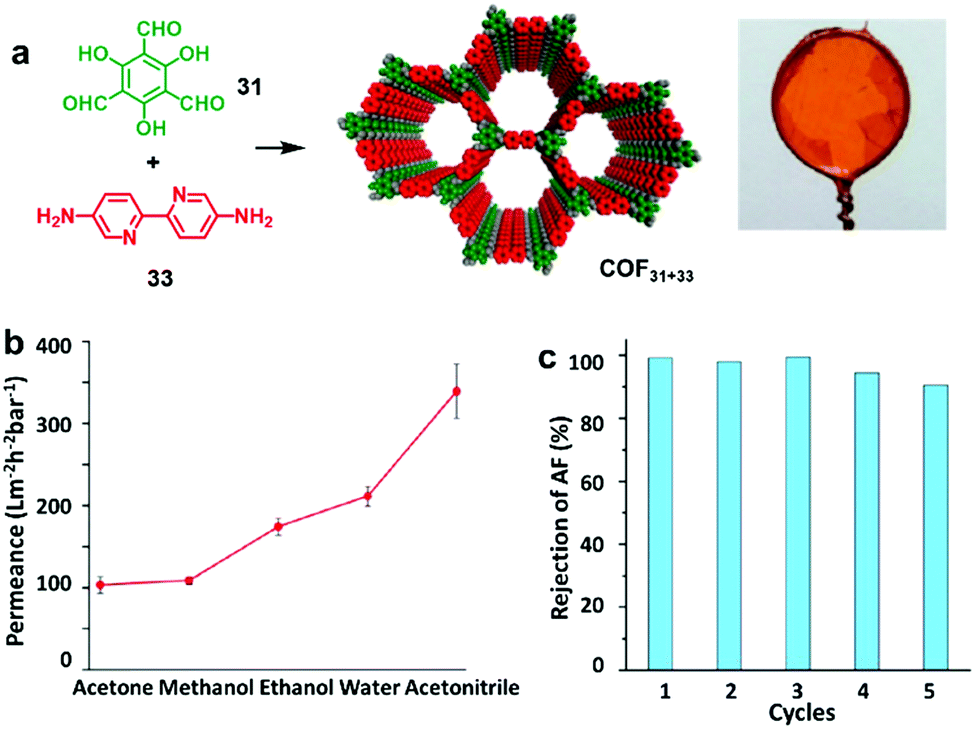 | ||
| Fig. 25 (a) Synthesis of COF31+33 at the liquid–liquid interface and its modelling and optical image; (b) permeances of pure solvents for COF31+33 thin film; (c) recyclability of the COF31+33 thin film for acid fuchsin (AF) rejection over 24 h for 5 cycles. Reproduced from ref. 51 with permission, Copyright 2017, The American Chemical Society. | ||
Dichtel and coworkers also reported the synthesis of a COF thin film through Schiff base reaction at the mesitylene-dioxane/water interface under the catalysis of Sc(OTf)3, which shows excellent nanofiltration performance.21 They prepared thin films of various thickness, ranging from 100 μm to 2.5 nm, by tuning the initial monomer concentration through precise calculation. The COF films were transferred onto polyethersulfone supports. The resulting membranes showed enhanced rejection of Rhodamine WT (up to 91%), a commonly used model water contaminant. The advantages of such a system include large area, tunable pore size, and customizable chemical composition, thus showing great promise in nanofiltration applications.
6.3 COFs formed at the liquid/solid interface
In liquid/solid interface synthesis, usually a solid substrate is introduced into the reaction solution or the reaction solution is drop cast onto the surface of an adsorbent. The favored interactions (e.g., polarity, electrostatic, π–π stacking, etc.) between the substrate surface and the resulting polymer network drive the growth of COF membranes or covalent monolayers at the surface of the solid support. Compared with air/liquid and liquid/liquid interface synthesis, liquid/solid interfacial synthesis can provide thin films or even monolayers already integrated on the solid substrates, such as silicon wafer and HOPG, which allow direct device fabrication and property measurement without the need of material transfer. By carefully controlling the initial monomer concentration in the drop-cast approach, it is possible to obtain covalent monolayers. | ||
| Fig. 26 (a) Structures of AVMs and the linear oligomers; (b) synthesis of COF3+34; (c) schematic illustration of the controlled separation of AVMs from the linear oligomers using the host–guest interactions with surface COF3+34; (d) corresponding STM images of the four separation stages shown in (c). The scale bars are 10 nm. Reproduced from ref. 15 with permission, Copyright 2018, Wiley. | ||
Another example of molecular recognition based on surface COFs was reported by Rosei et al. where the known COF7 was assembled on the HOPG surface.52 It was found that upon addition of a solution of C60 fullerene on top of COF7 supported by HOPG, adsorption of fullerenes within the defined pores was observed by STM (Fig. 27). Fullerene adsorption was also observed on top of boroxine rings of COF7. Both these sites were able to host fullerene molecules, as confirmed by STM characterization. Control experiments show that the presence of the COF layer is necessary for the stabilization and dispersion of fullerene molecules.
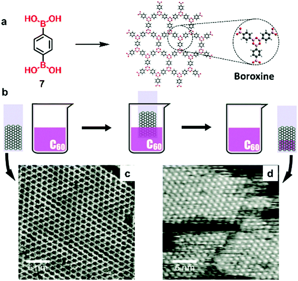 | ||
| Fig. 27 (a) Synthesis of COF7; (b) schematic illustration of dipstick preparation of the COF7/fullerene host–guest structure; (c) STM image of as-synthesized COF7 on the HOPG surface; (d) STM image of COF7 populated with C60 guest molecules. Imaging parameters: voltage Ut = −800 mV, tunneling current I = 100 pA. Reproduced with permission from ref. 52, Copyright 2015, The Royal Society of Chemistry. | ||
7. Concluding remarks
There has been tremendous progress in the design, synthesis, and property study of COF-based thin films or membranes within the past ten years or so. These structurally precise materials have shown great potential in various applications, such as water purification, energy storage, etc. However, some technical challenges, particularly in structure characterization, thickness control, and material processability, remain to be addressed.First, for covalent monolayers prepared through air–water interfacial polymerization using the Langmuir–Blodgett trough approach, it has been extremely difficult to characterize their structural order. To the best of our knowledge, there has been no successful STM characterization of such monolayers upon transferring them from the water surface to a solid substrate. It is hypothesized that some water droplets or gas bubbles are trapped underneath the monolayer, significantly diminishing the tunneling effect and making the image acquisition difficult. People have also tried using grazing incidence X-ray diffraction (GIXRD) to characterize covalent monolayers, but with limited success. In this regard, liquid–solid interfacial polymerization shows greater promise than air–water interfacial reactions. High-quality STM data of those single-layer framework structures have been routinely obtained. Nonetheless, development of novel powerful characterization tools that can provide the structural order information on covalent monolayers is highly desired.
Second, the domain size of these covalent monolayers or thin films prepared at a liquid surface (either air–water or liquid–liquid) is generally difficult to determine. But such information is particularly important for electronic device applications. On the other hand, in terms of material processability, the frameworks prepared at a liquid surface have advantages, such as the formation of free-standing thin films that can be transferred to other substrates for structure characterization or device fabrication. Moreover, given the flexibility of liquid surfaces, the thin films obtained via such an approach can also be folded, bent and stretched, all of which would be very challenging to achieve with a solid surface.
Third, it is still difficult to control the thickness of the COF materials prepared through interfacial polymerization, particularly at the liquid–liquid interface. The material thickness is highly dependent on both the monomer diffusion rate and the polymerization rate. For certain applications, such as molecular separation and water purification, thin membranes are highly desired due to their high permeability (flux). Therefore, development of new techniques that could achieve better control over the thickness of COF thin films or membranes would significantly facilitate their practical applications. The recently developed laminar assembly polymerization (LAP) method represents a promising strategy.
Fourth, for the COF monolayer grown on top of solid substrates (e.g., Cu, Ag, or Au), often the small molecule building blocks need to undergo vaporization under ultrahigh vacuum conditions to be deposited on the metal surface, followed by surface-catalyzed framework formation. Although the resulting thin films can usually be visualized with STM, the stringent requirement on the experimental setup strongly impedes its large-scale practical applications. On the other hand, as mentioned earlier, the Langmuir–Blodgett trough approach can significantly facilitate the preparation of large-area covalent monolayers under ambient conditions; however, the structural order of the obtained monolayer is usually hard to characterize. How to overcome such a dilemma (difficult synthesis and unambiguous characterization vs. convenient synthesis and difficult characterization) represents a grand challenge in this field.
Fifth, more experimental and theoretical information on the mechanistic insight into the catalytic activities of different metal surfaces is needed, such as the geometry of active sites, adsorbed intermediates, activation energy, etc. Such information would be of great importance for controlling the growth of COF monolayers at metal substrate surfaces as well as for their structure–property relationship study.
With further advancement of synthetic strategies as well as characterization techniques, it is anticipated that interfacial polymerization will play a more critical role in COF-based thin film or membrane preparation. Such customizable ordered framework materials through bottom-up design would have a significant impact on multiple fields with great potential in a broad range of applications, such as molecular separation, water purification, electronics, energy storage, sensing, etc.
Conflicts of interest
There are no conflicts to declare.Acknowledgements
The authors thank the University of Colorado Boulder and the K. C. Wong Education Foundation for funding support.References
- A. P. Côté, A. I. Benin, N. W. Ockwig, M. Keeffe, A. J. Matzger and O. M. Yaghi, Science, 2005, 310, 1166 CrossRef PubMed.
- Y. Jin, C. Yu, R. J. Denman and W. Zhang, Chem. Soc. Rev., 2013, 42, 6634–6654 RSC.
- J. Sakamoto, J. van Heijst, O. Lukin and A. D. Schlüter, Angew. Chem., Int. Ed., 2009, 48, 1030–1069 CrossRef CAS PubMed.
- S. Clair, M. Abel and L. Porte, Chem. Commun., 2014, 50, 9627–9635 RSC.
- J. F. Dienstmaier, D. D. Medina, M. Dogru, P. Knochel, T. Bein, W. M. Heckl and M. Lackinger, ACS Nano, 2012, 6, 7234–7242 CrossRef CAS PubMed.
- O. Ourdjini, R. Pawlak, M. Abel, S. Clair, L. Chen, N. Bergeon, M. Sassi, V. Oison, J.-M. Debierre, R. Coratger and L. Porte, Phys. Rev. B: Condens. Matter Mater. Phys., 2011, 84, 125421 CrossRef.
- L. Lafferentz, V. Eberhardt, C. Dri, C. Africh, G. Comelli, F. Esch, S. Hecht and L. Grill, Nat. Chem., 2012, 4, 215–220 CrossRef CAS PubMed.
- L. M. Falicov and G. A. Somorjai, Proc. Natl. Acad. Sci. U. S. A., 1985, 82, 2207–2211 CrossRef CAS PubMed.
- M. Bieri, M. T. Nguyen, O. Groning, J. M. Cai, M. Treier, K. Ait-Mansour, P. Ruffieux, C. A. Pignedoli, D. Passerone, M. Kastler, K. Müllen and R. Fasel, J. Am. Chem. Soc., 2010, 132, 16669–16676 CrossRef CAS PubMed.
- X. H. Liu, C. Z. Guan, S. Y. Ding, W. Wang, H. J. Yan, D. Wang and L. J. Wan, J. Am. Chem. Soc., 2013, 135, 10470–10474 CrossRef CAS PubMed.
- W. L. Dong, L. Wang, H. M. Ding, L. Zhao, D. Wang, C. Wang and L. J. Wan, Langmuir, 2015, 31, 11755–11759 CrossRef CAS PubMed.
- X. H. Liu, J. Y. Yue, Y. P. Mo, Y. Yao, C. Zeng, T. Chen, H. J. Yang, Z. H. Wang, D. Wang and L. J. Wan, J. Phys. Chem. C, 2016, 120, 15753–15757 CrossRef CAS.
- L. R. Xu, X. Zhou, Y. X. Yu, W. Q. Tian, J. Ma and S. B. Lei, ACS Nano, 2013, 7, 8066–8073 CrossRef CAS PubMed.
- L. R. Xu, X. Zhou, W. Q. Tian, T. Gao, Y. F. Zhang, S. B. Lei and Z. F. Liu, Angew. Chem., Int. Ed., 2014, 53, 9564–9568 CrossRef CAS PubMed.
- C. H. Liu, E. Park, Y. H. Jin, J. Liu, Y. X. Yu, W. Zhang, S. B. Lei and W. P. Hu, Angew. Chem., Int. Ed., 2018, 57, 8984–8988 CrossRef CAS PubMed.
- J. F. Dienstmaier, A. M. Gigler, A. J. Goetz, P. Knochel, T. Bein, A. Lyapin, S. Reichlmaier, W. M. Heckl and M. Lackinger, ACS Nano, 2011, 5, 9737–9745 CrossRef CAS PubMed.
- R. Gutzler, H. Walch, G. Eder, S. Kloft, W. M. Heckl and M. Lackinger, Chem. Commun., 2009, 4456–4458 RSC.
- J. W. Colson, A. R. Woll, A. Mukherjee, M. P. Levendorf, E. L. Spitler, V. B. Shields, M. G. Spencer, J. Park and W. R. Dichtel, Science, 2011, 332, 228–231 CrossRef CAS PubMed.
- D. D. Medina, J. M. Rotter, Y. H. Hu, M. Dogru, V. Werner, F. Auras, J. T. Markiewicz, P. Knochel and T. Bein, J. Am. Chem. Soc., 2015, 137, 1016–1019 CrossRef CAS PubMed.
- V. Muller, A. Hinaut, M. Moradi, M. Baljozovic, T. A. Jung, P. Shahgaldian, H. Mohwald, G. Hofer, M. Kroger, B. T. King, E. Meyer, T. Glatzel and A. D. Schlüter, Angew. Chem., Int. Ed., 2018, 57, 10584–10588 CrossRef PubMed.
- M. Matsumoto, L. Valentino, G. M. Stiehl, H. B. Balch, A. R. Corcos, F. Wang, D. C. Ralph, B. J. Mariñas and W. R. Dichtel, Chem, 2018, 4, 308–317 CAS.
- Y. Zhong, B. Cheng, C. Park, A. Ray, S. Brown, F. Mujid, J.-U. Lee, H. Zhou, J. Suh, K.-H. Lee, A. J. Mannix, K. Kang, S. J. Sibener, D. A. Muller and J. Park, Science, 2019, eaax9385 Search PubMed.
- Y. Jin, Y. Hu and W. Zhang, Nat. Rev. Chem., 2017, 1, 0056 CrossRef.
- Y. Yu, J. Lin, Y. Wang, Q. Zeng and S. Lei, Chem. Commun., 2016, 52, 6609–6612 RSC.
- Z. M. Gong, B. Yang, H. P. Lin, Y. Y. Tang, Z. Y. Tang, J. J. Zhang, H. M. Zhang, Y. Y. Li, Y. S. Xie, Q. Li and L. F. Chi, ACS Nano, 2016, 10, 4228–4235 CrossRef CAS PubMed.
- L. M. Wang, J. Y. Yue, X. Y. Cao and D. Wang, Langmuir, 2019, 35, 6333–6339 CrossRef CAS PubMed.
- C. Liu, Y. Yu, W. Zhang, Q. Zeng and S. Lei, Chem. – Eur. J., 2016, 22, 18412–18418 CrossRef CAS PubMed.
- Y. P. Mo, X. H. Liu and D. Wang, ACS Nano, 2017, 11, 11694–11700 CrossRef CAS PubMed.
- K. Dey, M. Pal, K. C. Rout, S. Kunjattu H, A. Das, R. Mukherjee, U. K. Kharul and R. Banerjee, J. Am. Chem. Soc., 2017, 139, 13083–13091 CrossRef CAS PubMed.
- B. Yang, J. Bjork, H. P. Lin, X. Q. Zhang, H. M. Zhang, Y. Y. Li, J. Fan, Q. Li and L. F. Chi, J. Am. Chem. Soc., 2015, 137, 4904–4907 CrossRef CAS PubMed.
- S. Kezilebieke, A. Amokrane, M. Abel and J. P. Bucher, J. Phys. Chem. Lett., 2014, 5, 3175–3182 CrossRef CAS PubMed.
- C. Morchutt, J. Bjork, C. Strasser, U. Starke, R. Gutzler and K. Kern, ACS Nano, 2016, 10, 11511–11518 CrossRef CAS PubMed.
- D. Zhou, X. Y. Tan, H. M. Wu, L. H. Tian and M. Li, Angew. Chem., Int. Ed., 2019, 58, 1376–1381 CrossRef CAS PubMed.
- K. Liu, H. Qi, R. Dong, R. Shivhare, M. Addicoat, T. Zhang, H. Sahabudeen, T. Heine, S. Mannsfeld, U. Kaiser, Z. Zheng and X. Feng, Nat. Chem., 2019, 11, 994–1000 CrossRef CAS PubMed.
- J. Eichhorn, D. Nieckarz, O. Ochs, D. Samanta, M. Schmittel, P. J. Szabelski and M. Lackinger, ACS Nano, 2014, 8, 7880–7889 CrossRef CAS PubMed.
- K. J. Shi, D. W. Yuan, C. X. Wang, C. H. Shu, D. Y. Li, Z. L. Shi, X. Y. Wu and P. N. Liu, Org. Lett., 2016, 18, 1282–1285 CrossRef CAS PubMed.
- N. A. A. Zwaneveld, R. Pawlak, M. Abel, D. Catalin, D. Gigmes, D. Bertin and L. Porte, J. Am. Chem. Soc., 2008, 130, 6678–6679 CrossRef CAS PubMed.
- C. Z. Guan, D. Wang and L. J. Wan, Chem. Commun., 2012, 48, 2943–2945 RSC.
- S. Clair, O. Ourdjini, M. Abel and L. Porte, Chem. Commun., 2011, 47, 8028–8030 RSC.
- Z. F. Cai, G. L. Zhan, L. Daukiya, S. Eyley, W. Thielemans, K. Severin and S. De Feyter, J. Am. Chem. Soc., 2019, 141, 11404–11408 CrossRef CAS PubMed.
- R. Tanoue, R. Higuchi, N. Enoki, Y. Miyasato, S. Uemura, N. Kimizuka, A. Z. Stieg, J. K. Gimzewski and M. Kunitake, ACS Nano, 2011, 5, 3923–3929 CrossRef CAS.
- W. Dai, F. Shao, J. Szczerbiński, R. McCaffrey, R. Zenobi, Y. Jin, A. D. Schlüter and W. Zhang, Angew. Chem., Int. Ed., 2016, 55, 213–217 CrossRef CAS PubMed.
- H. Sahabudeen, H. Qi, B. A. Glatz, D. Tranca, R. Dong, Y. Hou, T. Zhang, C. Kuttner, T. Lehnert, G. Seifert, U. Kaiser, A. Fery, Z. Zheng and X. Feng, Nat. Commun., 2016, 7, 13461 CrossRef CAS PubMed.
- S. Schlogl, T. Sirtl, J. Eichhorn, W. M. Heckl and M. Lackinger, Chem. Commun., 2011, 47, 12355–12357 RSC.
- T. Faury, S. Clair, M. Abel, F. Dumur, D. Gigmes and L. Porte, J. Phys. Chem. C, 2012, 116, 4819–4823 CrossRef CAS.
- J. Y. Yue, Y. P. Mo, S. Y. Li, W. L. Dong, T. Chen and D. Wang, Chem. Sci., 2017, 8, 2169–2174 RSC.
- F. Shao, W. Y. Dai, Y. Zhang, W. Zhang, A. D. Schlüter and R. Zenobi, ACS Nano, 2018, 12, 5021–5029 CrossRef CAS PubMed.
- H. Liu, Z. H. Zhang, C. Y. Wu, Q. Y. Pan, Y. J. Zhao and Z. B. Li, Small, 2019, 15, 1804519 CrossRef PubMed.
- R. Dong, H. Sahabudeen, H. Qi, M. Ballabio, M. Položij, S. Olthof, R. Shivhare, Y. Jing, S. Park, K. Liu, T. Zhang, J. Ma, B. Rellinghaus, S. C. B. Mannsfeld, M. Bonn, E. Cánovas, Z. Zheng, U. Kaiser, X. Feng and T. Heine, Angew. Chem., Int. Ed., 2020, 59, 6028–6036 CrossRef PubMed.
- D. B. Shinde, G. Sheng, X. Li, M. Ostwal, A. H. Emwas, K. W. Huang and Z. Lai, J. Am. Chem. Soc., 2018, 140, 14342–14349 CrossRef CAS PubMed.
- K. Dey, M. Pal, K. C. Rout, H. S. Kunjattu, A. Das, R. Mukherjee, U. K. Kharul and R. Banerjee, J. Am. Chem. Soc., 2017, 139, 13083–13091 CrossRef CAS PubMed.
- D. Cui, J. M. MacLeod, M. Ebrahimi, D. F. Perepichka and F. Rosei, Chem. Commun., 2015, 51, 16510–16513 RSC.
- G. Li, Y. Li, H. Liu, Y. Guo, Y. Li and D. Zhu, Chem. Commun., 2010, 46, 3256–3258 RSC.
| This journal is © The Royal Society of Chemistry 2020 |