
 Open Access Article
 This Open Access Article is licensed under a Creative Commons Attribution-Non Commercial 3.0 Unported Licence
Core–shell structured catalysts for thermocatalytic, photocatalytic, and electrocatalytic conversion of CO2
Sonali
Das
 a,
Javier
Pérez-Ramírez
*ab,
Jinlong
Gong
*c,
Nikita
Dewangan
a,
Kus
Hidajat
a,
Bruce C.
Gates
*d and
Sibudjing
Kawi
*a
a,
Javier
Pérez-Ramírez
*ab,
Jinlong
Gong
*c,
Nikita
Dewangan
a,
Kus
Hidajat
a,
Bruce C.
Gates
*d and
Sibudjing
Kawi
*a
aDepartment of Chemical and Biomolecular Engineering, National University of Singapore, Singapore. E-mail: chekawis@nus.edu.sg
bInstitute of Chemical and Bioengineering, Department of Chemistry and Applied Biosciences, ETH Zurich, Vladimir-Prelog-Weg, 1, 8093 Zurich, Switzerland. E-mail: jpr@chem.ethz.ch
cKey Laboratory for Green Chemical Technology of Ministry of Education, School of Chemical Engineering & Technology, Collaborative Innovation Center for Chemical Science & Engineering, Tianjin University, Tianjin, China. E-mail: jlgong@tju.edu.cn
dDepartment of Chemical Engineering, University of California, Davis, USA. E-mail: bcgates@ucdavis.edu
First published on 14th May 2020
Abstract
Catalytic conversion of CO2 to produce fuels and chemicals is attractive in prospect because it provides an alternative to fossil feedstocks and the benefit of converting and cycling the greenhouse gas CO2 on a large scale. In today's technology, CO2 is converted into hydrocarbon fuels in Fischer–Tropsch synthesis via the water gas shift reaction, but processes for direct conversion of CO2 to fuels and chemicals such as methane, methanol, and C2+ hydrocarbons or syngas are still far from large-scale applications because of processing challenges that may be best addressed by the discovery of improved catalysts—those with enhanced activity, selectivity, and stability. Core–shell structured catalysts are a relatively new class of nanomaterials that allow a controlled integration of the functions of complementary materials with optimised compositions and morphologies. For CO2 conversion, core–shell catalysts can provide distinctive advantages by addressing challenges such as catalyst sintering and activity loss in CO2 reforming processes, insufficient product selectivity in thermocatalytic CO2 hydrogenation, and low efficiency and selectivity in photocatalytic and electrocatalytic CO2 hydrogenation. In the preceding decade, substantial progress has been made in the synthesis, characterization, and evaluation of core–shell catalysts for such potential applications. Nonetheless, challenges remain in the discovery of inexpensive, robust, regenerable catalysts in this class. This review provides an in-depth assessment of these materials for the thermocatalytic, photocatalytic, and electrocatalytic conversion of CO2 into synthesis gas and valuable hydrocarbons.
 Sonali Das | Sonali Das received her bachelor degree in Chemical Engineering from Jadavpur University, India in 2012. She is currently pursuing her PhD under the supervision of Professor Sibudjing Kawi at National University of Singapore. Her research focuses on core–shell catalysts for dry reforming of methane and catalytic CO2 conversion. |
 Javier Pérez-Ramírez | Javier Pérez-Ramírez holds the Chair of Catalysis Engineering at ETH Zurich. His research pursues the design of heterogeneous catalysts and reactor concepts tackling current and future energy, resource, and environmental challenges of society. His work has been recognized by several awards, most recently the Paul H. Emmett Award in Fundamental Catalysis of the North American Catalysis Society. He directs a National Competence Center of Research in Catalysis in Switzerland and has a visiting appointment at the National University of Singapore within the Flagship Green Energy Program. |
 Jinlong Gong | Jinlong Gong studied chemical engineering and received his BS and MS degrees from Tianjin University and his PhD degree from the University of Texas at Austin under the guidance of C. B. Mullins. He currently holds a Cheung Kong Chair Professorship at the faculty of chemical engineering at Tianjin University. He has served on the editorial boards for several journals including Chemical Society Reviews, Chemical Science, and AIChE Journal. He has published >250 papers in peer-refereed journals and been listed as a co-inventor on 73 patents and applications. His research interests include catalytic conversions of green energy, utilizations of carbon oxides, and synthesis and applications of nanostructured materials. |
 Kus Hidajat | Kus Hidajat received his BSc (Chemical Engineering) in 1978 from the University of Manchester Institute of Science and Technology (UMIS), UK, and his PhD in Chemical Engineering from the University of Cambridge, UK in 1983. He is now an Associate Professor at the Department of Chemical and Biomoelcular Engineering at the National University of Singapore. His research interests include heterogeneous catalysis and catalytic utilization of biomass. |
 Bruce C. Gates | Bruce Gates is a professor of chemical engineering at the University of California, Davis, where his research group is active in investigations of catalysis by atomically dispersed supported metals and metal clusters, metal organic frameworks, zeolites, and other porous materials. The group strives to synthesize supported catalysts with high degrees of uniformity to understand them in depth, using characterization methods including X-ray absorption spectroscopy, infrared spectroscopy, and (in collaborations) scanning transmission electron microscopy and density functional theory to determine structures of the catalytic species with precision, even in the working state, for comparisons with kinetics and other catalyst performance data. |
 Sibudjing Kawi | Professor Sibudjing Kawi is a productive researcher and has published more than 285 international peer-reviewed journal articles. He obtained his PhD in Delaware and has been attached to the Department of Chemical and Bio-molecular Engineering at the National University of Singapore since 1994. In the past decade, his research has focused on the design and synthesis of nano-catalysts for green and sustainable development, such as CO2 reforming with methane to bio-syngas and hydrogen, CO2 hydrogenation, biomass gasification, and the water gas shift reactions. His expertise also includes the synthesis of novel inorganic membranes, as well as catalytic membrane reactors. |
1. Introduction
Rapid population growth and technological advances, powered by unrestrained fossil fuel exploitation, have led to significant increases in atmospheric anthropogenic emissions of greenhouse gases such as CO2 causing climate change at an accelerating pace and threatening the future of our living planet. Global anthropogenic CO2 emissions are currently estimated at about 36.5 gigatons per annum. Reduction in CO2 emissions has been recognized as essential in preventing the consequences of global warming in treaties such as the Kyoto Protocol and the Paris Agreement. In this context, carbon capture and storage (CCS) and, secondarily, carbon capture and utilization (CCU) are crucial for controlling CO2 emissions from human activities. CCU aims at capturing exhaust or atmospheric CO2 and using it as a feedstock in industrial processes to produce more economically valuable products. CO2 conversion to chemicals, fuels, concrete-building materials and microalgae fuels, and its application in enhanced oil recovery are some of the pathways of CCU.13,14 These can reduce industrial CO2 emissions, displace fossil fuel use and help to lessen atmospheric CO2. The use of CO2 for industrial production of fuels constitutes a ‘cycling’ pathway, whereby carbon is moved cyclically through different industrial systems over timescales of days, weeks or months. CO2 use to produce fuels using renewable energy sources enables the delivery of renewable energy in the convenient form of liquid fuels, which can be easily transported and stored. CO2 conversion to chemicals would provide a benefit in CO2 storage in a timeframe of the order of a few decades; however, the volume of CO2 that could be cycled through chemicals is quite low in prospect compared with what could be cycled through fuels.CO2 can be described as the ultimate climate-friendly source of the carbon that constitutes chemicals and fuels, but we emphasize that the use of CO2 to produce fuels and chemicals does not provide a net CO2 removal from the atmosphere—rather, it can displace fossil fuel consumption and may reduce net CO2 emissions. Estimates for the potential scale of CO2 utilization in fuels range from 1 to 4.2 gigatons per annum.13 CO2 capture and utilization to produce fuels and chemicals is, hence, potentially significant for helping to meet global emission targets and simultaneously offsetting the increasing demand for fossil energy and fossil feedstock-derived chemicals.
CO2 conversion into speciality chemicals such as urea and salicylic acid is already carried out with mature, well-established technologies, but the production scale is low and the effect on global CO2 emissions minimal. Technologies that may consume CO2 on a markedly larger scale include the conversion of CO2 into hydrocarbon or other liquid fuels, either directly by hydrogenation or indirectly via syngas production. In the indirect route, CO2 is used to reform hydrocarbons such as methane from natural gas or shale gas to produce synthesis gas (syngas, H2 + CO) by the dry or CO2 reforming of methane (DRM) process. Syngas components are among the key building blocks of the chemical industry and can be converted into hydrocarbons and oxygenates by Fischer–Tropsch (FT) synthesis or by methanol synthesis. Syngas may also be used as a source of hydrogen for other industrial processes or for fuel cells. The process of CO2 reforming of methane can complement processes for syngas production from other, more established technologies such as steam reforming of methane (SRM) or autothermal reforming (ATR). The ideal H2/CO molar ratio of syngas from DRM is 1, which is suitable for FT synthesis to give high yields of long-chain hydrocarbons. Mondal et al.16 conducted an economic evaluation and concluded that for a methanol production plant, the DRM process was characterised by a lower production cost and lower carbon footprint than SRM, assuming the availability of low-cost CO2 in sufficient purity.
Direct routes for CO2 conversion to fuels involve the reaction of CO2 with hydrogen to form CO, methane, methanol, olefins, dimethyl ether, etc., with the products depending on the catalyst, reactor, and operating temperature and pressure. CO2 reduction may be carried out by thermal catalysis, photocatalysis, or electrocatalysis. Thermal catalysis provides the advantage of more favourable kinetics and has received significant attention. Direct electrochemical reduction of CO2 with water under the influence of an external electric field is also in prospect an attractive process that combines the two steps of generating hydrogen from water and reduction of CO2 in a single step—that can be carried out under ambient conditions. Photocatalytic reduction of CO2 uses semiconductor materials to harvest solar energy and convert CO2 to CO, methane, methanol, or other compounds and can be operated under mild conditions without additional energy input.
The source of hydrogen used in the conversion of CO2 is critical in determining the overall environmental impact (and economics) of the processes. For the CO2 reduction process to be net CO2 consuming, it is necessary to have H2 produced from non-fossil sources of H2 using renewable energy sources.17 Production of H2 by water splitting with electricity generated from solar or wind sources is considered to be a potentially economical route to establishing a sustainable carbon-based cycle and remains a focus of active research. In a review, Perathoner et al.18 elaborated on possible routes for introducing renewable energy into the chemical production value chain using CO2 as a carbon source. Essentially, CO2 can be used as an energy vector for converting renewable energy, if renewable sources are used for producing the H2 to hydrogenate CO2. The conversion of CO2 to methane or liquids such as methanol, olefins, etc. that can be easily stored and transported provides a convenient way to harness renewable energy.
To displace fossil-derived carbon through CCU, it will be necessary to convert CO2 with renewable H2 into fuels or chemicals at costs that are competitive to allow integration into the energy and chemical chain. A recent life cycle analysis by González-Garay et al.19 concluded that the cost of producing hydrogen from water electrolysis takes up 27% to 79% of the cost of green methanol production from CO2 captured from coal power plant emissions, depending on the source of electricity (nuclear, wind, solar, or biomass). Currently, green methanol from a coal plant exhaust CO2 is predicted to cost 1.3 to 2.6 times that of its fossil-based analogue, which can be expected to drop significantly with a drop in electricity cost for hydrogen production. This analysis was conducted assuming point sources of CO2 with high CO2 concentrations, and not atmospheric CO2. Atmospheric CO2 is significantly more challenging and expensive to capture and convert than point-source CO2 such as that in an industrial exhaust stream. The ambitious long-term goal of CCU is economic capture and conversion of atmospheric CO2.
The preceding few decades have witnessed a boom in research focused on candidate technologies to convert CO2 into hydrocarbons via direct or indirect routes.20–28 However, most of the prospective technologies are immature and require significant improvement prior to implementation on an industrial scale. As with most chemical conversion technologies, the key to success is the catalyst—which must have suitable activity, selectivity, and stability and not be too expensive. Thus, developing and tuning catalytic materials have taken centre stage in research on CO2 conversion technologies, with marked advances having been made in recent years. Yet significant challenges remain.
In the indirect route of CO2 conversion by dry reforming of hydrocarbons, highly active and selective catalysts have been developed, but most lose their activity rapidly under the harsh conditions of the process—as a result of sintering of the catalytically active components and/or formation of surface-blocking deposits of carbonaceous material (coke).26
A major challenge in CO2 conversion to methanol is the equilibrium constraint that necessitates operation at low temperatures—there is a classic thermodynamics-kinetics trade-off here. The high stability of CO2 and poor reaction kinetics make it difficult to achieve high conversions at low temperatures. Further, in CO2 conversion to methanol, methanol selectivity is a challenge because of important side reactions such as the reverse water gas shift (RWGS), which consumes valuable hydrogen and yields CO and H2O. Catalyst stability is also a concern.22 FT synthesis of hydrocarbons from CO2 suffers from very low yields of any one product, as a smear of hydrocarbons (with a statistical distribution) is formed, along with oxygenates, depending on the catalyst. These limitations make the cost of product separation a major concern. Hence, a key focus of research on thermocatalytic CO2 hydrogenation processes is to discover catalysts that can improve CO2 activation and increase selectivity to desired products while suppressing competing reaction pathways.
The primary challenge for electrochemical CO2 reduction with water is poor energy efficiency and the requirement of very high potentials to drive the reaction towards desirable products. The conversion of CO2 into hydrocarbons and oxygenates such as alcohols, involving multiple electron (>6) reduction pathways requires high overpotentials, which implies high energy input and the significant occurrence of the parasitic side-reaction that is hydrogen evolution from water, leading to low overall faradaic efficiency for CO2 reduction. Electrochemical CO2 reduction can also form a wide variety of products such as CO, formate, formaldehyde, methane, ethylene, alcohols, etc., and achieving high selectivity to one product is still a challenge, specifically for C2+ hydrocarbons and oxygenates. Inefficient performance of the electrocatalysts has been recognized as the greatest challenge for practical electrochemical CO2 reduction.29
Similarly, for photocatalytic CO2 reduction, the key challenge is the poor energy efficiency of the available systems to absorb and convert solar energy to hydrogenate CO2; even with the best known methods, the conversions are characterised by extremely low product yields. And there are only limited means to control product selectivity. The complexity, efficiency and cost of photocatalytic reactor systems also remain a concern, and some of the key design challenges include light collection/concentration, even illumination, efficient mass transfer, and ease of separation of photocatalysts from products.30 The intermittent nature of sunlight creates an inherent constraint for photo-catalytic systems using sunlight as the photon source. Alternate sources of photon, such as artificial light from conventional or LED lamps, consume electricity and are limited by their own wall-plug efficiencies. We do not discuss the design of reactors in this review but instead concentrate primarily on the catalyst. The achievable rates of photocatalytic reduction of CO2 with the best known photocatalysts today remain insufficient for commercial exploitation.17 When water is used to hydrogenate CO2 directly, water reduction to form hydrogen becomes a parasitic side reaction that competes with CO2 reduction and reduces the overall productivity. It is hence imperative to improve the photo-efficiencies and selectivities of the catalysts and the overall reaction rates of the process.
Thus, there is significant need to discover CO2 conversion catalysts that are improved in all these respects. The multiplicity of these needs has led to intensive research on catalysts with more intricate structures than conventional catalysts. Conventional solid catalysts traditionally used in industrial processes consist of an active phase dispersed on a stable porous support, often with a high specific surface area (even hundreds of square meters per gram). Conventional preparation techniques for dispersing catalytic phases on supports, such as impregnation, deposition–precipitation, sol–gel synthesis, etc. are carried out economically on commercial scales, but they do not provide much control of the precise structure of the catalyst at the atomic and nano scales. Consequently, non-uniform catalyst structures are the rule, sometimes with poor dispersions of the active phase—to the detriment of the selectivity, activity, and perhaps the stability of the catalyst.
But recent rapid advances in nanotechnology and materials synthesis methods have now made it possible to synthesize nanomaterials with well-defined sizes, shapes, crystal facets, and morphologies, all providing opportunities to tailor catalysts for effective performance for specific conversions. These advances are at the core of progress in CO2 conversion catalysis, and especially noteworthy are core–shell materials—these allow a controlled integration of complementary components of various materials (usually metals, metal oxides, metal sulphides, or carbon-based materials) in unique morphologies—to exhibit synergistic effects that combine multiple functionalities in one structure.31
Broadly, a core–shell structure is a composite nanomaterial that consists of an inner core material surrounded by a shell material, each having structural and/or compositional features with dimensions at the nano scale. This term in the context of catalysis was originally coined for concentric spherical layered core–shell structures, with the shell being porous to allow transport of reactants and products through it, and the core usually also being porous to allow transport throughout it. Terms such as “egg yolk,” “egg white,” and “egg shell” have been used frequently for such catalysts. The typical motivations for using core–shell catalysts have focused on optimisation of transport-reaction trade-offs, allowing efficient utilization of the catalytically active material—for example, so that catalytically active species in the interior regions of the materials are not starved of reactants because of transport limitations, but possibly being starved of undesirable reactants, such as those causing catalyst deactivation.
Now, with growing interest in core–shell catalysts, their definition has been extended to include structures with distinct boundaries between the two (or more) constituent materials, whereby the inner material is partially or completely encapsulated by the outer material and possibly even chemically bonded to it, with the core and/or shell sometimes being so small as to have dimensions at the nano or even the atomic scale.32
A core–shell material may have highly distinctive functionalities, arising from the ranges of physical and chemical properties of the core and shell, influenced by their compositions, structures, and dimensions. Thus, core–shell nanomaterials offer flexibility for integrating multiple functionalities such as catalytic activity, adsorption capacity, conductivity, photocatalytic activity, dielectric properties, biocompatibility, etc. that make them attractive for applications in catalysis, energy storage, optoelectronics, and bio-nanotechnology. In catalysts, the active sites may be in the core or the shell (or both), or, at the interface. Some such catalysts are bifunctional, with products formed on one kind of catalytic site transported to another. Other than combining the individual synergistic functionalities of the core and shell, the core–shell catalysts also offer new properties that arise from the interaction between the core and shell.
Core–shell materials have contributed to significant recent progress in CO2 conversion research. Sinter-resistant core–shell catalysts have been developed that can withstand the high temperatures of CO2 reforming reactions for extended periods without significant coke formation.33 Bifunctional (tandem) core–shell catalysts have been made to have significantly higher selectivities in CO2 hydrogenation than conventional catalysts to desired products such as methanol, C2+ hydrocarbons, and oxygenates.2 Core–shell structured catalysts with a lattice mismatch between the core and shell have been used to change the electronic properties of the active sites and tune the adsorption energies of the intermediate reactant species to promote product selectivity or reduce energy barriers for electrocatalytic CO2 reduction.34,35 Core–shell structures have also drawn interest in photocatalysis because they can markedly improve efficiency by separation of photo-generated charges and by improving light absorption through the integration of suitable materials and interfaces.36
Several recent reviews capture the rapid progress in research on CO2 conversion technologies, development of catalysts, reaction mechanisms, and process improvements, with suggestions about future research directions.20–26,37–39 Pérez-Ramírez et al.17 reviewed CO2 conversion for production of energy and chemicals by catalytic, photocatalytic, and electrocatalytic methods, emphasizing opportunities for design of CO2 conversion catalysts based on fundamental theoretical calculations. Song et al.22 reviewed progress in catalysis of the production of hydrocarbons by thermocatalytic hydrogenation of CO2, with a focus on reaction mechanisms and routes to value-added chemicals. Sun et al.40 reviewed advances in direct and indirect routes of CO2 upgrading in terms of catalyst design, performance, and reaction mechanisms, considering both experimental work and calculations at the level of density functional theory (DFT). Wang et al.21 reviewed recent accomplishments in the materials field for CO2 reduction by photocatalysis, electrocatalysis, and photoelectrocatalysis. Homogenous and heterogeneous catalysis of electrochemical CO2 reduction have also been reviewed recently.29,34,41 Other reviews summarize progress in catalyst development for CO2-assisted reforming of methane.24,26,42
In view of the significant recent work on core–shell catalysts in the context of CO2 conversion, we posited that there is a need for a critical review focused on this topic. Thus, whereas most reviews of core–shell structures focus primarily on materials synthesis strategies, and the general applications,31,32,43 we focus instead on the unique functionalities of core–shell structures and their potential applications and advantages in the conversion of CO2 into fuels and chemicals by thermocatalytic, photocatalytic, and electrocatalytic methods. We also highlight the limitations of known core–shell catalysts, both from an economic and a technological perspective and emphasize the need for rigorous benchmarking investigations and technoeconomic analyses to assess the potential of these materials for large-scale application.
This review is divided into the following sections: introduction and classification of core–shell nanomaterials; advantages of core–shell materials in heterogeneous catalysis; application of core–shell materials in CO2 utilization reactions, specifically, (a) CO2 reforming of methane into syngas, (b) thermocatalytic hydrogenation of CO2 to CO, methane, methanol, and C2+ hydrocarbons, (c) electrocatalytic reduction of CO2 into CO, hydrocarbons, or oxygenates, (d) photocatalytic hydrogenation of CO2 into methane, syngas, hydrocarbons, or oxygenates, and an outlook to the future and proposed directions for further research.
2. Classification of core–shell catalysts
There is an enormous variety of core–shell materials in terms of composition, morphology, properties, and applications, and in the following sections we classify them.2.1. Composition
Core–shell materials are broadly divided into inorganic, organic, and inorganic–organic materials. Inorganics include metals, metal oxides, metal salts, etc., and organics include polymers, graphene, carbon nanotubes, etc.The shell is commonly a metal or metal oxide. Silica in its many forms has received especially wide attention as a shell material. Silica coatings on core nanoparticles provide benefits such as high resistance to agglomeration in suspensions and stability at high temperatures. SiO2 shells are easy to synthesize with good control of thickness, porosity, and morphology by sol–gel chemistry or micro-emulsion methods, and there are many examples of metal@SiO244–55 and metal oxide@SiO2.56–59
Metal oxides including TiO2,60,61 Al2O3,62 CeO2,12 ZrO2,63 CuO,64 and others have also been investigated as shell components of core–shell structures. For example, TiO2-containing materials offer favourable optical and chemical properties, making them ideal candidates for energy-related applications, including photocatalysis. Core–shell structures with TiO2 shells have been synthesized by hydrolysis, precipitation, and hydrothermal methods.60,61,65 CeO2 has a high oxygen storage capacity, making it a good candidate catalyst component for redox processes such as combustion and reforming. Core–shell materials with CeO2 shells12,66–69 have been synthesized by precipitation, hydrothermal, and self-assembly methods. Transition aluminas are the most frequently used catalyst supports because of their low cost, good hydrothermal stability, acid/base properties, and ease of production with tailored surface areas and pore volumes, and these are also common shell materials.62,70 Atomic layer deposition (ALD) has emerged as a good method to coat nanoparticles with Al2O3 shells with fine control of the shell thickness.62 Beyond simple metal oxides, materials such as crystalline aluminosilicates (zeolites),71,72 which have crystalline porous structures, have also been investigated as shells, offering molecular size-selectivity (shape selectivity), high specific surface areas, and acidic centres.
Metal@metal particles constitute another important class of inorganic core–shell materials, for which the deposition of one metal on the surface of another metal nanoparticle can create new properties and even induce fundamental electronic effects characterising the metals. Au, Pt, Pd, Ni, Cu, Co, Ag, and others have been used as shells on other metal nanoparticles.31 Metal@metal nano-structures can be used to tune the electronic properties of the overlayer metal and have been used extensively in electrocatalysis.
Hybrid functional materials such as metal organic frameworks (MOFs) have been explored in core–shell structures, serving as either the core or shell. MOFs as shells can act as selective membranes affecting transport because of their ordered porous structures and the functionalities present on the organic linkers or anchored to the nodes. MOF crystals can be used to form highly dispersed metal nanoparticles encapsulated inside carbon or carbon nitride structures by carbonisation of the organic linkers.77
Among the various classes of core–shell structures, inorganic@inorganic and inorganic@carbon/MOF are the more commonly used types for heterogeneous catalysis, and their applications in CO2 conversion are discussed in detail in the following sections.
2.2. Morphology effects
Even nanoparticles confined in the frameworks of a crystalline porous material such as a MOF or a mesoporous support are now regarded as core–shell structures—this newly expanded classification is appropriate because the materials serve purposes similar to those of the originally defined sphere-in-shell structures and are understood on the basis of similar principles – only the dimensions are different. Thus, in this review, we use the term “core–shell nanomaterials” synonymously with “encapsulated structures.” On the basis of structure and morphology, we classify these materials broadly into core–shell, yolk–shell/hollow structures and sandwiched core–shell structures, as shown in Fig. 1.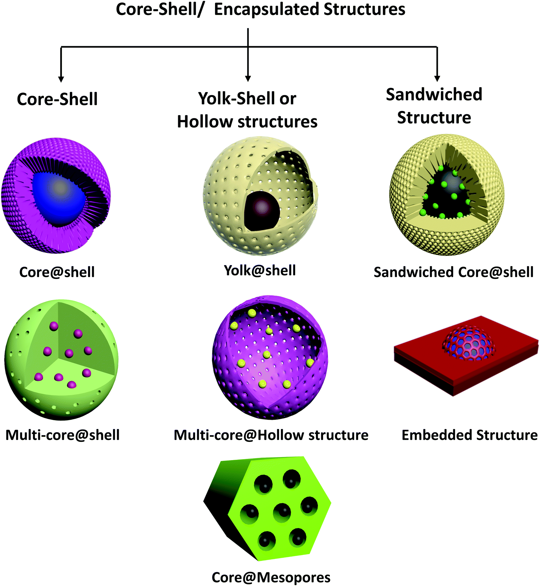 | ||
| Fig. 1 Schematic of types of core–shell structures based on morphology. | ||
We emphasize that notwithstanding their often unique and intricate structures, core–shell catalysts can be seen as more complex examples of common catalyst structures, namely supported metals, metal oxides and alloys. Single or multi-core shell metal@metal oxide, metal@carbon, metal oxide@metal oxide catalysts can be seen as special cases of supported metals and metal oxides on various supports, in which the interface with the support almost completely surrounds the supported particles. Yolk@shell or yolk@hollow structures may be considered to be extensions of nanoparticles embedded in the channels of mesoporous supports. Metal@metal core–shells are again a form of bimetallic nanoparticles, with a greater degree of spatial segregation of the separate metals than in alloys.
Yolk@shell structures are usually synthesized by coating the core with a sacrificial soft or hard template, followed by coating to form the shell. The template is then removed to produce a cavity. Silica63,78 and organic polymers75,79 such as resorcinol–formaldehyde resins can be removed by acid etching and calcination, respectively, and have been used extensively as templates to synthesize hollow structures. On the basis of the synthesis procedure, it is inferred that yolk@shell structures may have the core or yolk anchored in the hollow shell, or it may even be movable with no fixed contact with the shell (in nano-rattle structures). Hollow structures may also be synthesized by self-templating approaches.80,81
Multiple cores may also be encapsulated in hollow structures, wherein the core particles are partially embedded in the shell material to prevent agglomeration over time. Metals/metal oxides in hollow SiO2,51,75,82 CeO2,69,76 zeolite crystal,83,84etc. structures have been reported for catalytic applications. Controlled thermolysis of core–shell MOF crystals has also been employed to form hollow yolk@shell structures.77
Another category of sandwiched core–shell structures is nanoparticles partially embedded in a support. For several reducible oxide supports such as CeO2 or TiO2, it has been observed that thermal treatment of conventional metal/support catalysts under reducing/oxidizing conditions may result in the spontaneous encapsulation of the metal by the support material creeping onto it (a phenomenon referred to with the term “strong metal–support interaction” or SMSI). Although synthesis of such materials does not involve the precise process of core–shell material synthesis, the encapsulated structures formed under reaction conditions can cause them to exhibit properties similar to those of conventional core–shell materials.
3. Core–shell catalysts for CO2 conversion
In the introduction (Section 1), we discussed the major challenges in various CO2 conversion processes. Core–shell structured materials offer some unique properties that make them suitable to address some of these challenges. In the following section (Section 3.1), we address the properties of core–shell materials that make them potentially superior catalytic materials and evaluate structure–property relationships that form the basis for rational design of core–shell catalysts for specific applications. Although these properties and benefits of core–shell catalysts pertain to many heterogeneous catalytic processes, we focus the discussion primarily on CO2 conversion. Following the discussion on the beneficial properties of core–shell materials, we focus on the various CO2 conversion pathways – thermocatalytic, photocatalytic, and electrocatalytic, and consider the recent investigations of core–shell catalysts in each of these applications, with an emphasis on the specific technological needs and the corresponding advantages of core–shell materials.3.1. Benefits of core–shell materials in catalysis
The core–shell structure, when correctly designed and optimised for a particular catalytic application, can provide performance superior to that of the generally applied conventional catalysts. Indeed, the motivation for core–shell structures is, often, to enhance essential properties of conventional catalysts. For example, in conventional supported metal catalysts, an appropriate choice of support can introduce a bifunctional character to the catalyst (e.g., a hydrogenation function of metal nanoparticles dispersed on a metal oxide with an acidic function). A core–shell structure with the same constituents may be designed to optimise the interaction between the metal and support (say, the core and the shell materials, respectively) to maximise the benefits of the bifunctionality (which may be related to the characteristic distances between the two functions). In our discussion of beneficial properties of core–shell structures in this section, we attempt to highlight the similarities between core–shell materials and more conventional forms of catalysts and discuss how core–shell catalysts can be improvements over the conventional ones.We stress that the functional benefits offered by core–shell catalysts also come at a cost. The synthesis of core–shell structures often involves complex and elaborate recipes that involve multiple steps and are more expensive than those of the conventional catalysts used industrially. Although these more intricate structures sometimes provide superior catalyst performance, it remains to be established whether this benefit justifies the increased manufacturing cost. One also has to determine whether the methods of manufacture of a core–shell catalyst are sufficiently reliable, for example to allow a catalyst manufacturer to provide performance guarantees of new and replacement catalyst charges. Detailed techno-economic analyses and extensive benchmarking studies with candidate catalysts and conventional catalysts are required to assess the practical potential of core–shell catalysts. Early successes might be expected to lead to improvements in manufacturing methods and increasing confidence in catalysts in this new class.
The major functional benefits offered by core–shell catalysts are discussed below.
The structures of core–shell catalysts can be effective in minimizing catalyst sintering. In a core–shell structure, the active nanoparticles may be encapsulated or partially embedded in a layer of thermally stable material that acts as a physical barrier to hinder particle migration and agglomeration. In metal@metal oxide core–shell catalysts, ultra-small metal nanoparticles (metal clusters, e.g., Pt, Au, Pd, Ni, Cu) can be stabilized under extreme conditions by encapsulation in a thermally stable metal oxide shell or silica shell. For example, silica shells in Ni@SiO2, Au@SiO2, and Pd@SiO2 are highly effective in limiting metal agglomeration and preserving the original metal particle sizes.33,52,88 Nano-structured oxides with poor thermal stability (such as nanosheets, nanorods, etc.) can also be protected from sintering at high temperatures by coating with mesoporous silica.89 Core–shell materials consisting of active metal or metal/metal oxide composite core within a thermally stable porous metal oxide or silica shell (which often is chemically inert) have often been reported to minimize sintering of active components in CO2 conversion (dry reforming, CO2 methanation, or hydrogenation to methanol).
Particle sintering is also accelerated by steam in the reaction atmosphere. This is a concern for thermocatalytic CO2 reduction, which produces significant amount of steam as a by-product.90 The high partial pressure of steam, even at reaction temperature of 300 °C, causes rapid agglomeration and crystal growth of the commonly used catalysts (such as Cu/ZnO/Al2O3). Although there are reports of core–shell catalysts to tackle this sintering problem, a number of conventionally used shell materials that are employed to prevent particle migration (such as mesoporous silica) may not be stable under high steam partial pressures at elevated temperatures. In superheated steam, surface Si–O–Si bonds in mesoporous silica can be hydrolysed by water adsorbed on silanol groups, leading to collapse of the pore structure and loss of surface area.91 Mixed oxides, ZrO2, TiO2, zeolites, alumino-phosphates generally have higher hydrothermal stabilities than mesoporous silica and γ-alumina, and the level of hydrothermal stability varies among different forms of silica; for example, SBA-15 and KIT-1 are more stable than MCM-41, MCM-48 and HMS.92 Thus, the choice of shell materials and their reactivities are important criteria for application of core–shell structures to resist sintering under high-temperature and hydrothermal conditions.
Techniques used with conventional supported catalysts to suppress sintering include modification of support surfaces to increase the strength of bonding to the metals on them and use of low metal loadings per unit of support surface area to minimize coalescence. Core–shell structures, in contrast, provide physical barriers between particles to provide significant resistance to sintering, and, perhaps even more important, they may strongly hinder the formation of structure-destroying filamentous carbon that is highly detrimental to conventional catalysts used at high temperatures. Thus, we suggest that these advantages of core–shell catalysts may emerge as crucial to their future applications, although we recognize the cost issues—for example, catalysts with metal oxide shells around metals require a coating step in the synthesis (e.g., by sol–gel, ALD, or other techniques), making them more expensive than conventional supported catalysts. Techno-economic analyses and comparisons between conventional and core–shell sinter-resistant catalysts are needed to resolve matters and guide future applications.
Other than directly combining separate catalytic functions, a core–shell structure may also be designed to integrate materials with high reactant adsorption capacities that indirectly benefit the catalytic activity. For example, a prerequisite for high CO2 conversion in any catalytic process is adsorption of CO2 on the catalyst, before it can be converted to the corresponding intermediates. However, the non-polar CO2 often interacts only weakly with many catalytic materials. More important, in CO2 conversion processes that are carried out in the presence of liquid phases, such as electrocatalytic CO2 reduction with water, poor solubility of CO2 and low CO2 concentration at the catalyst surface can seriously impede the reactions. CO2 conversion catalysts have been integrated with CO2 sorbent materials with high surface areas and CO2 affinities (such as MOFs) in core–shell structures to aid in enhanced adsorption of CO2 in catalytic, photocatalytic, and electrocatalytic reactions.10,93
An important benefit of the multi-functionality of core–shell catalysts is evident in photocatalytic CO2 conversion. The activities of photocatalysts under the influence of light irradiation is governed by the ability of the photocatalyst to absorb the visible light and generate the charges that ultimately drive the reaction. However, the bandgaps of commonly used semiconductor photocatalysts such as TiO2 fall in the UV region, leading to very low absorption and photoexcitation upon exposure to visible light. Photosensitizer materials can be integrated into core–shell structures for intimate contact with the photocatalyst to increase visible light absorption and improve the efficiency of the reaction.94 Further, a semiconductor, which is an essential component of a photocatalyst to generate photo-induced charges, may not provide the ideal catalytic sites for CO2 conversion. Other materials with more nearly optimal CO2 activation and adsorption properties may be more suitable for selective CO2 reduction using the photo-generated electrons in the semiconductor. Core–shell materials allow the integration of such co-catalysts with the semiconductor materials in desirable structures.
The bottom line is that core–shell structures can combine materials that have different desirable properties that benefit one process, while allowing the individual components to maintain their individual identities and properties. Such combinations are well known in traditional heterogeneous catalysts and particularly in bifunctional catalysis (e.g., when the support incorporates functionalities that complement those of the metal particles dispersed on it). A motivation for adopting a core–shell architecture is to enhance the synergy between these separate functionalities by optimizing the interactions between the different catalyst components.
Consider the example of FT synthesis: the transformation of CO + H2 into isoparaffins, which are desired compounds for high-octane-number gasoline, is known to occur by a two-step process. CO and H2 are first converted into linear hydrocarbons on FT catalysts followed by their subsequent hydrocracking and isomerization into branched hydrocarbons on acidic sites of the catalyst. In a conventional bifunctional catalyst, the different active sites are randomly distributed, creating an open environment for the two reactions to occur independently and randomly. Because of the non-uniform distributions of the FT-active sites and acidic sites in a conventionally made catalyst, intermediates in the reactions may exist for various times of transport between functions—thus giving a range of opportunities for undesired reactions. Core–shell catalysts in prospect can mitigate such selectivity limitations by sharpening the distribution of distances between the separate catalytic sites. For example, on a core@shell H-beta zeolite-encapsulated Co/Al2O3 catalyst, the intermediate linear hydrocarbon products formed on the core FT catalyst have to diffuse out through a uniform zeolite shell. The uniform thickness of the zeolite shell around the FT catalyst core provide equal diffusion length for the intermediates over the acidic zeolite sites, effectively increasing the product selectivity.95
For CO2 conversion applications, the possibility of tuning product selectivity by combining catalytic functions in a core–shell catalyst is significant for thermocatalytic hydrogenation of CO2, which generally yields a variety of products with limited selectivity to any one product.96 Thermocatalytic CO2 hydrogenation to C2+ hydrocarbons and oxygenates involves multi-step processes, which include some reaction pathways that pertain to the above-mentioned FT synthesis. Reactions of CO2 hydrogenation and further conversion of the hydrogenated intermediate product may be carried out in tandem on core–shell catalysts: for example, the conversion of CO2 to methanol on the core catalyst followed by dehydration of methanol to dimethyl ether on acidic sites in the shell.
A benefit of having the separate catalytic materials in core–shell geometries that are uniform at the nanoscale rather than randomly mixed components is the degree of control over the proximity of the different materials and the optimization of the reactant atmosphere in each of the separate sections of the catalyst. Combinations of different catalytic sites are also present in traditional supported catalysts, but they are generally inhomogeneous in distribution; and the commonly employed synthesis methods do not provide much control over the spatial distribution of these sites. We recognize a trade-off: the more precisely optimised structures in core–shell catalysts and the consequent superiority in performance are offset by the complexity and higher cost of manufacture.
Core–shell catalysts also allow the segregation of acidic and basic sites in single nanostructures without neutralizing each other, facilitating reactions that are consecutively catalysed by acidic and basic sites.97
Similarly, for reactions that produce various products as a result of competing side-reactions, a size-selective shell may be used to selectively produce products in a desired size range. An example of use of core–shell structures with a size-selective shell to control product selectivity was demonstrated for the hydrogenation of furfural ( ) to furfuryl alcohol (
 ) with Pt/CeO2 containing catalysts.99 End-on adsorption of furfural on the catalyst surface through the C
![[double bond, length as m-dash]](https://www.rsc.org/images/entities/char_e001.gif) O group results in the hydrogenation of the CO group to form furfuryl alcohol, the desired product. A planar adsorption of furfural with both the CO and CC groups coordinating with the catalyst leads to hydrogenation of both groups to form tetrahydrofurfuryl alcohol (
O group results in the hydrogenation of the CO group to form furfuryl alcohol, the desired product. A planar adsorption of furfural with both the CO and CC groups coordinating with the catalyst leads to hydrogenation of both groups to form tetrahydrofurfuryl alcohol ( ). A core–shell Pt–CeO2@UIO-66-NH2 catalyst with a UIO-66-NH2 MOF shell was synthesized, whereby the narrow windows (6 Å) of the MOF forced the furfural (6.6 Å × 4.9 Å × 1.6 Å) to align and adsorb only vertically on the catalyst surface. The core–shell catalyst achieved >99% selectivity and 99.3% yield of furfuryl alcohol whereas Pt–CeO2 which could achieve a maximum 89.7% selectivity to furfuryl alcohol, followed by further hydrogenation to tetrahydrofurfuryl alcohol, 1,2-pentanediol etc.
As discussed in Section 3.1.3, core–shell catalysts have been widely investigated and shown to allow control of the normally wide product distribution in FT synthesis.96 Encapsulated catalysts with a FT catalyst core and a zeolite shell with appropriate pore size and shell thickness have exhibited improved selectivity to gasoline-range branched hydrocarbon products. n-Paraffins and olefins of varying chain lengths formed on the core and subsequently diffused out through the pores of the zeolite shell. Although even longer-chain linear alkanes and olefins can diffuse out through the zeolite pores, the rate of diffusion depends on the hydrocarbon chain length and size, and the longer waxy hydrocarbons are inferred to spend longer times in contact with the acidic sites of the zeolite shell, where they undergo cracking and isomerization. Consequently, the selectivity for the intermediate carbon-chain length (gasoline-range) hydrocarbons (C5–C11) is increased.100–102 Again, the same effect also pertains qualitatively to conventional catalysts; on the way to exit a classical supported catalyst, the linear hydrocarbon products pass over the support surface and diffuse through the pores; but the core–shell architecture imposes a uniform diffusion pathway for all the intermediates and reduces the randomness in the extent of the secondary reactions. For example, a Co–SiO2@ZSM-5 catalyst was shown to have higher selectivity (73%, Ciso/Cn = 2.1) to C5–C1 hydrocarbons than a physical mixture of Co–SiO2 and ZSM-5 catalysts (54%, Ciso/Cn = 0.9).103 A SAPO-34-encapsulated Fe3C catalyst was found to have a high selectivity to light olefins while almost completely suppressing the formation of C6+ hydrocarbons because of the limiting pore size of SAPO-34.104 Similarly, the concept of using size-selective shells to control product selectivity has been extended to the thermocatalytic hydrogenation of CO2, which takes place by a modified FT synthesis route.105
It is important to draw attention to the similarities and differences between metal@metal core–shell structures and metal alloys. In an alloy, the atoms of one metal are incorporated in the lattice structure of another, forming a kind of (sometimes) nearly uniform solid solution. A core–shell bimetallic structure is characterised by some degree of metal segregation, with the shell being enriched in one metal compared to the core. Functionally, in terms of catalysis, both alloy and core–shell materials are often intended to achieve the same effect, which is to alter the chemical properties of the metal surface, for example, by changing the Fermi level of the metal, which in turn determines the strengths of adsorption of various reaction intermediates and the rates of elementary reactions on the surface. According to the d-band model,112,113 the strength of adsorption of reactants and intermediates on a metal surface can be correlated with the electron d-band structure of the metal. Both solid solution alloys and core–shell bimetals are characterised by shifts in the d-band position through a combination of strain and ligand effects.114,115 The ligand effect refers to the weakening/strengthening of binding of adsorbates induced by downshift/upshift of the d-band centre because of the interaction between the d-bands of constituent metals in the bimetallic particle. The strain effect is caused by a lattice mismatch between the lattice parameters of the core and the shell materials in a core–shell structure and by the insertion of a second metal with different atomic radius in the lattice of the first metal in a bulk alloy. The ligand effect decays faster with distance than the strain effect, approximately within 1–2 monolayers from the surface compared to <6 monolayers for the strain effect. In a core–shell structure, the ligand effect of the underlying substrate on the surface metal may decay significantly with the shell thickness; thus, the ligand effect is expected to play a more significant role in alloys than in core–shell structures. Another major point of distinction between solid solution alloys and core–shell structures is in the “ensemble” effect. In a solid solution alloy of composition AxBy, the exposed surface contains both A and B atoms. The ensemble effect refers to the change in the catalytic properties of an ensemble of surface atoms when the composition of the ensemble changes. A DFT study by Nørskov's group.116 led to the conclusion that the ensemble effect can be described by a simple linear interpolation model in which the adsorption energy at a mixed metal site is an average of the properties of the constituent metals. A core–shell structure of the form B@A or AxBy@A, on the other hand, exposes only A atoms on the surface for adsorption of reactants, and this may be favourable in the cases for which the adsorption energy on A is more nearly optimum for a particular catalytic reaction than that on B.
Thus, overall, both alloys and metal@metal core–shells are used with the aim of modulating the electronic properties of the adsorbent metal surface; uniform alloys achieve that goal by a combination of strain, ligand, and ensemble effects and core–shell combinations do that mainly by the strain effect and to some extent, the ligand effect. In a way, core–shell structures decouple the effect of “strain engineering” from the effect of compositional change and “ensemble effects” that are manifested in alloys, and this can be of advantage depending on the requirements of the application.
It is important to note that the structure of a bimetallic particle can change over time in a reaction environment, depending on the atmosphere, temperature, pressure, etc. For example, a homogeneous alloy can undergo segregation of the metals to develop into a core–shell structure when exposed to a reactive atmosphere. Thermal annealing of alloys may result in a segregation of one metal into the surface or subsurface, driven by the difference in surface energy.117 The environment and the nature of adsorbates can also cause a restructuring of the surface; for example, subjecting bimetallic (PtNi) particles to alternating O2 and H2 atmospheres was observed to result in a reversible structural change with a NiO-rich surface formed in the oxidising atmosphere and a Pt-rich surface in the reducing atmosphere.118 Preferential leaching of one metal from the surface of an alloy in the presence of solutions (such as in electrochemical cells) can also lead to core–shell structures with the shell being deficient in the leached metal.119 The opposite is also possible, whereby an initial core–shell structure changes to a homogenous alloy over time.
In photocatalytic systems, the formation of interfaces or heterojunctions between two materials can increase the separation and lifetime of photo-generated charges, benefiting photocatalytic reaction rates.121 A heterojunction between an n-type and a p-type semiconductor results in a space-charge region at the interface, inducing an electric field that directs the transport of photo-generated electrons to the conduction band of the n-type semiconductor and of holes to the valence band of the p-type semiconductor—resulting in more efficient charge separation and diffusion to the surface where the photocatalytic reaction occurs. Similarly, the formation of a metal/semiconductor interface creates a Schottky barrier, and the metal acts as an electron trap for the photo-generated electrons from the semiconductor, thus reducing charge recombination. Core–shell structures can be engineered to create such interfaces with intimate contact between suitable materials and also to craft morphologies that facilitate fast charge diffusion from the bulk to the material surface, where the reaction occurs.
Thus, core–shell structured nanomaterials have some unique advantages in catalysis, also allowing the flexibility to combine separate functions for specific purposes. These general properties and benefits of core–shell catalysts are represented pictorially in Scheme 1, along with the type of catalysis—thermally driven, light-driven, or electrochemically driven, to which these properties pertain.
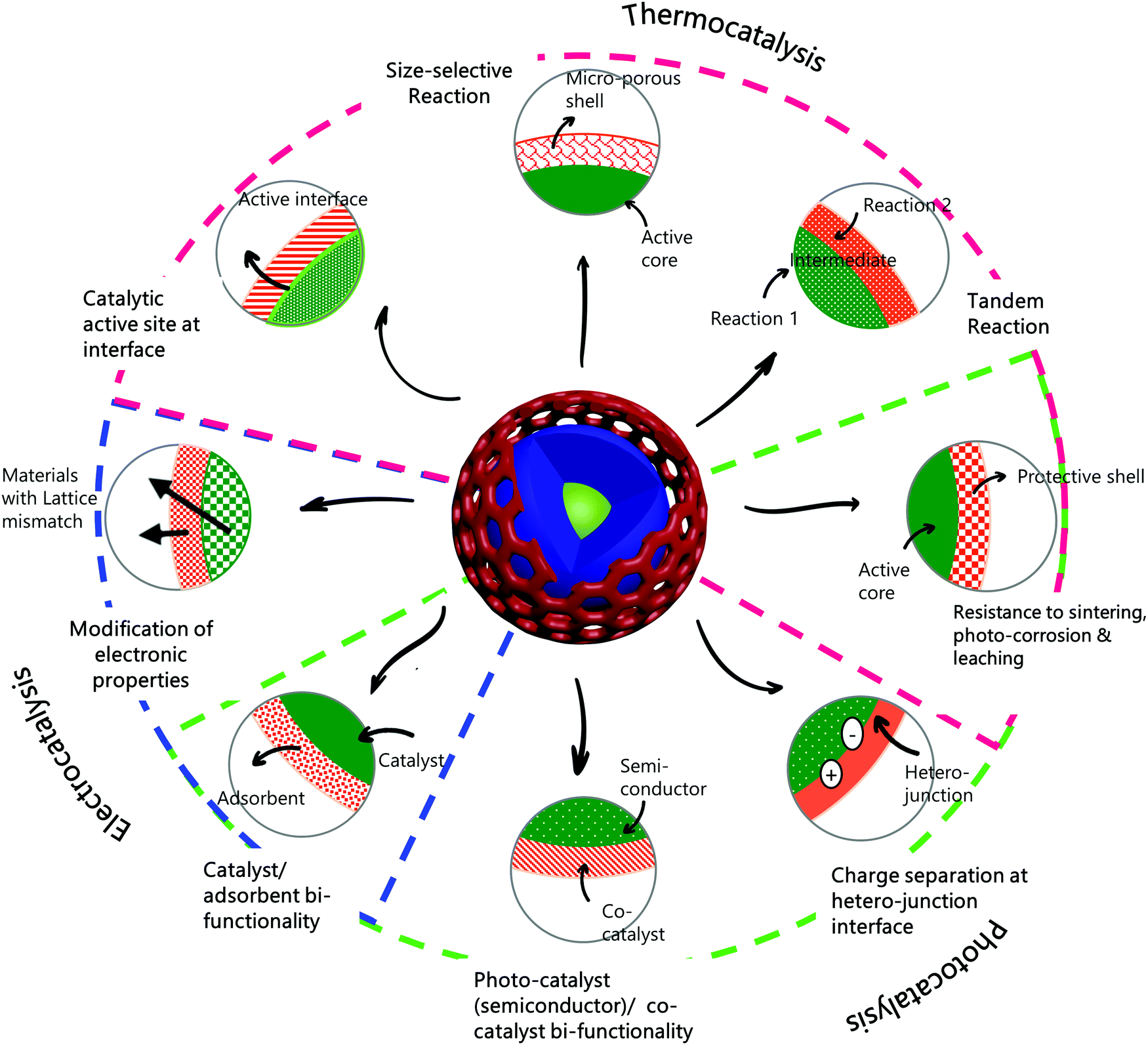 | ||
| Scheme 1 Properties and advantages of core–shell structures in catalysis. Properties denoted with magenta, green, and blue lines are relevant to thermocatalysis, photocatalysis, and electrocatalysis, respectively. | ||
In the preceding few years, substantial progress has been made in addressing the challenges in CO2 conversion processes using core–shell structured materials. In Scheme 2, we summarise the major challenges in the various routes of catalytic CO2 conversion and the benefits offered by core–shell catalysts to address them. In the following sections (Sections 3.2–3.4), we consider each of these CO2 conversion processes in detail, focusing on the application of core–shell materials. Each section starts with a brief introduction to the process, current challenges and desirable traits of the catalyst, and then, an in-depth analysis of recent research progress toward the application of core–shell structured nanocatalysts and their suitability in the respective processes.
 | ||
| Scheme 2 Properties of core–shell catalysts and applications in CO2 conversion. | ||
3.2. Core–shell catalysts for thermocatalytic CO2 conversion
3.2.1.1. Introduction. In dry reforming of methane, CO2 is used as a soft oxidant for the catalytic reforming of methane to produce a mixture of CO and H2 that is a platform for chemical synthesis, a source of H2, or a fuel used in power generation. CO2 (or dry reforming) of methane (eqn (1)) has the potential to complement industrial H2 production through steam methane reforming, and it is of particular environmental interest because it converts both of the major greenhouse gases CO2 and CH4. DRM is a highly endothermic reaction reflecting the high stability of both reactants; hence, it requires high temperatures (600–1000 °C) for significant conversions. The ideal H2/CO molar ratio in the DRM product is 1, but the simultaneous occurrence of the RWGS reaction (eqn (2)) consumes hydrogen to produce water and reduce the H2/CO ratio to <1. Noble metals such as Pt, Pd, Ru, and Rh and transition metals such as Ni, Cu, and Co are highly active for dry reforming reactions.25
| CH4 + CO2 → 2CO + 2H2 ΔH0298 = 248 kJ mol−1 | (1) |
| CO2 + H2 → CO + H2O ΔH0298 = 41.2 kJ mol−1 | (2) |
| CH4 → C(s) + 2H2 ΔH0298 = 75 kJ mol−1 | (3) |
| 2CO → C(s) + CO2 ΔH0298 = −172 kJ mol−1 | (4) |
As a consequence of its high activity and ready availability, Ni as a catalyst or catalyst component (alone or in alloys) has been widely investigated for DRM. A major challenge for the large-scale application of DRM is the rapid deactivation of the catalysts in operation resulting from sintering of the active metals and the deposition of deactivating coke on the catalyst. Coke deposition may result from the cracking of methane (eqn (3)) or disproportionation of CO (eqn (4)). Coke can deposit as amorphous or graphitic layers on the active metal surface, blocking active sites; alternatively, carbon nanotubes can form, which damage the integrity of the catalyst structure and cause expansion of the catalyst bed, leading to blockage and disruption in continuous operation. Hence it is crucial to develop catalysts that minimize coke formation and maintain activity under the harsh reaction conditions of DRM.
3.2.1.2. Performance of core–shell structures. Core–shell catalysts find excellent application in DRM technology, especially in enhancing the stability and coke-resistance of catalysts. Core–shell materials offer high thermal stabilities, resistance to sintering, and bifunctional properties, which aid in reducing the rate of coke formation and deactivation during DRM, compared to conventional catalysts.33 We recognize that disadvantages of core–shell catalysts relative to conventional catalysts, however, include their greater complexity and cost of synthesis and the possibility of lower overall activity associated with mass transfer limitations imposed by the shell. The shell can also block part of the active metal surface, making it unavailable for reaction.
In the following section, we discuss the two major benefits of core–shell materials as DRM catalysts, along with relevant examples from recent investigations.
3.2.1.2.1. Resistance to sintering and coking. Metal sintering causes catalyst deactivation in DRM not only through loss of active surface area, but also through increased growth of whisker-type carbon, which deactivates the catalyst and causes loss of the catalyst structure. The rate of carbon deposition from CH4 or CO2 dissociation is highly dependent on the size of the metal nanoparticles. Kim et al.122 concluded from an investigation of Ni supported on alumina aerogel that a minimum Ni particle diameter of around 7 nm is required for the generation of filamentous carbon in DRM. Filamentous carbon growth on Ni starts by the dissolution of surface carbon in the Ni particles to form a nickel carbide phase, followed by growth of carbon nanotubes catalysed by the metallic Ni. Carbon nanotubes of smaller diameter are not stable, and hence smaller Ni nanoparticles are more resistant to this kind of coking in the DRM reaction. Thus, good control on the metal dispersion and prevention of metal agglomeration during DRM is an effective strategy to increase the catalyst stability.
Core–shell materials with a porous, thermally stable shell on the active metal core are ideal to stabilize the metal nanoparticles and minimize metal sintering at high temperatures. As discussed in Section 3.1.1, metal@SiO2 or metal@other metal oxide exhibits much more resistance to sintering than conventional supported metal catalysts. Under the high-temperature DRM conditions, such nanomaterials help to maintain the initial metal particle size and active surface area. If the initial metal particle size in the core–shell catalyst is small (lower than what is needed to promote the growth of carbon nanotubes) and metal sintering is inhibited by the core–shell structure, the catalyst may be able to largely resist formation of filamentous coke during the course of the DRM reaction. In contrast, a conventional supported metal catalyst, even if it incorporates very small metal nanoparticles initially, will slowly undergo metal sintering to form larger nanoparticles, which accelerate carbon nanotube formation and subsequent catalyst deactivation. The encapsulation of the metal nanoparticles by a shell can also sterically hinder the growth of filamentous carbon on the metal, thereby suppressing deactivation.
In the preceding decade, there has been vigorous research on sinter-resistant core–shell catalysts for DRM. Metal@SiO2 catalysts are the most extensively investigated catalysts in this class, with mesoporous silica being a highly suitable protective shell because of its high thermal stability, high specific surface area, tunable pore size distribution, and ease of synthesis. The silica shell thickness and porosity are easily tuned by adjusting the silica precursor concentration, hydrolysis time, and use of surfactants. Several investigators have reported Ni@SiO2 catalysts for DRM;33,48,52,88 Ni is highly active for DRM but also favours coke formation, and supported Ni/SiO2 or Ni/Al2O3 catalysts are characterised by continuous deactivation and coke formation.48 Ni@SiO2, in contrast, has been reported to be have stable performance with negligible coke formation for ≥100 h in DRM.48 Ni@SiO2 may be synthesized by coating pre-synthesized NiO or surfactant-capped Ni nanoparticles by mesoporous silica by a sol–gel method88 or by one-pot microemulsion methods.48 One-pot synthesis methods often yield multi-core@shell structures with more than one Ni nanoparticle encapsulated in a porous silica sphere. Under high-temperature DRM conditions, it has been observed that these multiple metal cores inside one silica sphere can migrate inwards and agglomerate to form a single Ni core during the reaction.48,52 However, as long as the silica shell remains thermally stable, sintering of Ni nanoparticles across different silica spheres does not occur, so that the metal sintering is limited to individual core@shell modules. Starting with multi-core Ni@SiO2 with <5 nm-diameter Ni nanoparticles, Peng et al.48 observed that the multiple cores sintered to form single central Ni cores of average diameter 7.8 nm after 100 h of DRM at 800 °C, and these were still sufficiently small to prevent formation of coke. Sandwiched SiO2@Ni@SiO2 catalysts with Ni nanoparticles held at the interface of two silica layers have been reported by Han et al.3 and Bian et al.15 (Fig. 2). These catalysts have multiple metal nanoparticles spatially dispersed on supports and subsequently coated with shells that provide confinement and limit mobility.
 | ||
Fig. 2 Silica coating as a strategy to prevent sintering and coke formation in DRM. (a) Schematic representation of resistance of SiO2 coated Ni nanoparticles to sintering and coke-deposition in DRM. Reproduced with permission from ref. 3. Copyright (2014), Wiley. (b and c) TEM images of fresh phyllosilicate-derived Ni/SiO2 (NiPS) and sandwich structured core–shell Ni/SiO2@silica (Ni-PS@silica-0.4) catalysts, respectively. (d and e) Catalytic performance of Ni/SiO2 (NiPS) and core–shell Ni/SiO2@silica (Ni-PS@silica-0.4) catalysts, respectively, during DRM. Conditions: 600 °C, WHSV = 60![[thin space (1/6-em)]](https://www.rsc.org/images/entities/char_2009.gif) L gcat−1 h−1, CO2:CH4:He = 1:1:1. (f and g) TEM images of spent Ni/SiO2 (NiPS) and core–shell Ni/SiO2@silica (Ni-PS@silica-0.4) catalysts after 2.5 h and 24 h DRM, respectively, under above-stated conditions. (h) TGA–DTA profiles of used catalysts. Heavy coke deposition and metal sintering was observed for the supported Ni/SiO2 (NiPS) catalyst, causing reactor blockage within 2.5 h. The core–shell catalyst demonstrated stable DRM performance and negligible coke formation and metal sintering, as observed by TEM and TGA of used catalysts. Reproduced with permission from ref. 15. Copyright (2017) Wiley. L gcat−1 h−1, CO2:CH4:He = 1:1:1. (f and g) TEM images of spent Ni/SiO2 (NiPS) and core–shell Ni/SiO2@silica (Ni-PS@silica-0.4) catalysts after 2.5 h and 24 h DRM, respectively, under above-stated conditions. (h) TGA–DTA profiles of used catalysts. Heavy coke deposition and metal sintering was observed for the supported Ni/SiO2 (NiPS) catalyst, causing reactor blockage within 2.5 h. The core–shell catalyst demonstrated stable DRM performance and negligible coke formation and metal sintering, as observed by TEM and TGA of used catalysts. Reproduced with permission from ref. 15. Copyright (2017) Wiley. | ||
Metal@SiO2 core–shell structures have also been reported for other metals and metal alloys such as Co@SiO2,123 NiCo@SiO2,49 NiCu@SiO2,45 RuCu@SiO2,47etc. Bimetallic core–shell structures can be synthesized by routes similar to those used for mono-metallic structures and can provide enhanced activity or selectivity in DRM by virtue of the synergy of the two metals. For example, NiCu@SiO2 was found to exhibit higher H2 selectivity and yield than Ni@SiO2 by suppressing the RWGS reaction by virtue of uniform alloying of Ni with Cu.45 A NiCo@SiO2 bimetallic core–shell catalyst was reported to show enhanced DRM activity and absolute selectivity to H2 and CO at 900 °C, even at almost 100% conversion.49 The catalyst maintained good stability during the DRM reaction at 800 °C for more than 1000 h. As in conventional supported metal catalysts, uniformity of alloy formation in core–shell structures depends on the synthesis procedure. Tao et al.45 reported the significance of controlling the concentration of a metal precursor to synthesize uniform bimetallic core–shell structures with single nanoparticle cores using a microemulsion method.
Apart from attempts to prevent sintering and maintain particle size, attempts have been made to use core–shell structures to preserve the exposure of certain active facets of the metal nanoparticle. For example, Pd nanocubes with exposed [100] planes are expected to have higher activity in DRM than nano-spheres, because the low-coordination [100] plane of Pd has high activity for methane dissociation, which is often rate determining in DRM.124 Under DRM conditions, however, such metal nanocube structures can agglomerate, resulting in a loss of exposed active facets. Noble metals have also been used in such core–shell structures for DRM. Yue et al.54 encapsulated Pd nanocubes with exposed [100] planes in mesoporous SiO2 spheres. The core–shell Pd nanocube@m-SiO2 catalyst showed higher activity and stability than the conventional supported catalyst by preventing agglomeration of Pd nanoparticles, maintaining higher surface area and mesoporous structure. However, a slight “rounding” of the Pd nanoparticles was observed after 10 h of reaction, suggested to have resulted from the melting of Pd at the Pd–SiO2 interface, indicating that the silica shell was not entirely effective in preserving the active facets of Pd nanocubes. In another investigation, however, a mesoporous silica shell was shown to effectively protect and preserve the morphology and active [100] and [110] planes of CeO2 nanorods in a Ni/CeO2@SiO2 core–shell catalyst at 750 °C.89
The thickness, porosity, and stability of the silica shell are important in determining the activity and sinter-resistance of core–shell catalysts. Li et al.81 varied the shell thickness of Ni@SiO2 from 3.3 to 15.1 nm and compared the activities of the catalysts at a high WHSV (1440 L gcat−1 h−1). They observed that a 11.2 nm-thick mesoporous silica shell on the ∼12 nm-diameter Ni cores was optimum in increasing DRM activity (turnover frequency or TOF) while maintaining sinter-resistance of the catalyst structure. A low shell thickness of only 3.3 nm, however, was insufficient to impart thermal stability in DRM at 800 °C, and it collapsed, resulting in metal sintering and deactivation. Yet a greater shell thickness of 15.1 nm also was suboptimal, as cross-linking of the silica shells and reduction in porosity occurred in the presence of steam in the DRM reaction atmosphere, with a reduction in catalytic activity. Such a volcano shaped dependence of DRM activity on shell thickness was also reported for Co@SiO2 catalysts.123
The effect of shell porosity on DRM activity was investigated by Pang et al.47 for RuCo@SiO2 catalysts. Various surfactants (CTAB, PVP), or none, were employed in the synthesis of the silica shell to impart different shell porosities. Although a higher shell porosity did improve the DRM activity, it was observed that at high reaction temperatures the observed effect of shell porosity became less significant. It is likely that at high reaction temperatures, the reactions in all the catalysts with the various porosities were significantly influenced by transport limitations, resulting in their having similar apparent activities.
Porosity and structure of silica shells can also be modified by post-treatment of the metal@silica materials under hydrothermal conditions. For example, Li et al.80,125 subjected Ni@SiO2 catalysts to a hydrothermal treatment in an alkaline environment, resulting in the partial conversion of the silica shell into a lamellar Ni-phyllosilicate phase. The formation of this phase increased the porosity of the shell and further increased the dispersion of Ni in the shell, resulting in a strong metal–SiO2 interaction and limited mobility for sintering. A 2.6 times higher specific activity was observed for this post-treated catalyst at 800 °C than for the Ni@SiO2 catalyst without treatment.
The effects of diffusion limitations can also be reduced by using yolk@shell or core@hollow structures. More important, yolk@shell structures can minimize the adverse blocking of active sites in core–shell catalysts by virtue of the empty space between the core and shell. Several yolk@shell and hollow structured catalysts such as Ni-yolk@SiO2,81 NiCe-yolk@SiO2,126 multi-Ni@hollow silica,127 NiPt@hollow silicalite-1,128etc. have been reported for DRM. In an investigation of the effects of varying shell thicknesses in Ni@SiO2 core–shell catalysts, it was observed that the core–shell structure evolved into a yolk–shell structure after calcination when the shell thickness exceeded 11.2 nm.81 A comparison of DRM activity at 800 °C (under kinetically controlled conditions) between a core–shell Ni@SiO2 (8.6 nm shell thickness) and a yolk–shell Ni@SiO2 (11.2 nm shell thickness) showed a higher specific activity of 0.14 mol gcat−1 min−1vs. 0.19 mol gcat−1 min−1 for the yolk–shell catalyst. The turnover frequencies characterising the two catalysts, however, were almost same, 78 s−1, and the increase in DRM activity was likely evidence of the higher exposed Ni surface area in the yolk–shell catalyst (37 μmol gNi−1) compared with only 28.5 μmol gNi−1 for the core–shell catalyst.
Multi-Ni@hollow silica spheres (HSS) catalysts were synthesized by a one-pot micelle method,127 whereby multiple Ni nanoparticles <5 nm in diameter were embedded in hollow silica spheres. In comparison with the Ni/HSS and Ni/SiO2 catalysts prepared by impregnation, the Ni@HSS catalyst had better activity and stability, reaching 94.4% and 95% conversions of CH4 and CO2 at 800 °C for 55 h, with negligible coke formation. However, an activity comparison with a Ni@SiO2 multi-core@shell catalyst (with non-hollow silica spheres) was not reported, leaving open questions about the effects of the hollow structure on DRM activity and stability. Indeed, there are hardly any reports that directly compare the catalytic performance of similar core–shell and yolk–shell materials for DRM to delineate the effects of yolk–shell structure on the specific activity, number of exposed metal sites, intrinsic activity, and stability. Although a greater number of exposed metal sites is expected in yolk–shell structures, there can be differences in the activities of the active sites in the various catalysts because of various interactions of the metal with the support.
The type of coke generated in DRM can vary depending on the morphology of the core/yolk@shell. Yang et al.50 observed that a Ni@SiO2-yolk@shell structured catalyst was characterised by less coke formation (and mostly filamentous carbon) than a Ni@SiO2-core–shell catalyst that was characterised by the formation of encapsulating layered coke. Filamentous carbon formation is associated with the dissolution of carbon into Ni clusters, and the reshaping of the Ni clusters, leading to their detachment from the support. The steric hindrance provided by the SiO2 shell in the core–shell structure prevents the generation of filamentous coke while layered encapsulating coke is still formed on the Ni, extending into the pores of the SiO2 shell and leading to catalyst deactivation. The yolk@shell structure, because of the space between the Ni and the shell, was able to accommodate some filamentous coke, which did not significantly affect the catalytic activity.
Recently, hollow hierarchical core–shell structures have been developed using hollow Ni-phyllosilicate spheres as Ni carriers, followed by coating with mesoporous SiO2.46,58,82 Upon reduction, the Ni-phyllosilicate partially decomposed to form nanoparticles of Ni (<5 nm in diameter) embedded in the phyllosilicate matrix and held at the interface with another SiO2 layer. This encapsulation increases the metal–support interaction and sinter resistance, while at the same time preventing growth of carbon nanotubes. The hollow structure provides easy access of the reactants to the active sites. A hierarchical Ni-Phy@SiO2 hollow sphere catalyst tested for 600 h at 700 °C demonstrated stable performance.
Although the literature of core–shell catalysts for DRM is dominated by materials with SiO2 shells, a few investigations have been reported for catalysts with other materials as the shells, and these can also activate the reactants and facilitate bifunctional reactions in addition to providing sinter-resistance. Depending on the properties of the shell material, coke elimination by preferential CO2 activation may also be achieved. The bifunctional effects on coke resistance in core–shell catalysts are discussed in the next section (Section 3.2.1.2.2).
Ni@Al2O3 catalysts synthesized by an inverse microemulsion method70 and atomic layer deposition (ALD)62,129 have been reported for DRM. Baktash et al.62 investigated the effect of the number of ALD coatings on Ni nanoparticles on the shell thickness and DRM performance of Ni@Al2O3. Five cycles of ALD yielded an Al2O3 layer a few nanometres thick that was sufficient to prevent Ni particle sintering at temperatures up to 800 °C. A clear trend was established showing the effect of activity and number of ALD cycles, with a greater number of ALD cycles lowering the shell porosity and DRM activity, presumably because of increased mass transfer resistance. It was observed, however, that the Ni@Al2O3 catalyst underwent deactivation at a lower temperature (525 °C) because of coke deposition, and it is possible that a greater number of ALD coats is needed to achieve coke resistance at lower temperatures. Another study reported Ni@Al2O3 synthesized by a micro-emulsion method. Stable performance of the Ni@Al2O3 catalyst was observed over 50 h in a flow reactor at 800 °C, although ∼15% coke was deposited in the used catalyst.70 The relatively high coke content in the used catalyst, notwithstanding the core–shell structure and resistance of the catalyst to sintering, may be the result of the acidic nature of Al2O3 that favours methane decomposition.
Ni@CeO2 core–shell structures have also been investigated for CO2 reforming of methane, with the work motivated by the high redox activity and oxygen vacancies of CeO2,130 whereby the CeO2 shell can assist both in CO2 activation and provide sinter resistance. Improved CO2 activation by the CeO2 shell by virtue of its redox nature can further reduce coke formation in DRM (see further discussion in Section 3.2.1.2.2). Ni@TiO2 structures have also been applied for DRM;131,132 however, there have been only limited investigations and limited evidence that TiO2 as a shell provides significant sinter-resistance or coke-resistance in DRM. An investigation of Ni/SiO2@MOx (M = Si, Zr, Ti, Al, Mg) led to the conclusion that at 800 °C under DRM conditions, the TiO2 shell was unable to maintain its structure and showed distinct crystallization and aggregation of separate TiO2 and Ni phases.133 Under the same conditions, Al2O3, ZrO2, MgO, and SiO2 shells were more stable and effective in preventing sintering of the Ni nanoparticles.
The high sinter-resistance of core–shell structures under severe thermal conditions also makes them highly desirable for chemical looping CO2 reforming processes that subject the catalyst to continuous thermal and redox cycles. In a chemical looping process, a given overall reaction is separated into stages in which separate reactions take place, specifically, whereby oxygen storage materials (OSM) are reduced and regenerated in a cyclic fashion through the progress of the separate reactions and are transferred between reactors. In chemical-looping dry reforming of hydrocarbons, fuel conversion to syngas is conducted in two spatially or temporally separated half-steps: (1) reaction of the fuel with OSM, leading to syngas production and reduction of the OSM and (2) OSM re-oxidation with CO2. Metal oxides incorporating Cu, Fe, Ni, and Mn, for example, are evidently the most promising oxygen carrier candidates. However, the practical application of chemical looping reforming is impeded by the serious sintering of the metal oxides in the repeated redox cycles. Core–shell structures with chemically and thermally stable shell materials such as ZrO2 have been considered for long-term stability in chemical looping dry reforming of methane. For example, a Fe2O3/ZrO2@ZrO2 catalyst consisting of Fe2O3 nanoparticles decorating a ZrO2 support and coated with a thin mesoporous ZrO2 layer exhibited excellent redox activity for the conversion of CO2 to CO and stability for 100 redox cycles.134 Perovskites such as LaxSr1−xFeO3 have also been used as shells covering metal oxides to increase activity and stability in chemical looping partial oxidation of methane.135
3.2.1.2.2. Improving CO2 activation (bifunctional catalysis). Coke deposition in DRM can be reduced by enhancing CO2 activation and increased oxidation and removal of carbon species or coke precursors from the metal surface. For catalysts with basic or redox-active supports such as MgO, La2O3, CeO2, ZrO2, etc., CO2 activation occurs on the support or the metal–support interface. Coating metal nanoparticles with such supports can perform the dual function of imparting structural stability and promoting CO2 activation at the metal–support interface. The metal–support interfacial areas in core–shell structures can be greater than those in conventional supported catalysts.
CeO2 is widely used as a support in oxidation and reforming applications because of its redox properties and high oxygen mobility. CeO2 can undergo substantial changes as the cerium cations switch between Ce4+ and Ce3+ while the fluorite structure is maintained. In DRM, when Ce4+ is reduced to Ce3+, this transformation can release the lattice oxygen which oxidises carbon species at the metal/CeO2 interface to form CO. The oxygen vacancies formed thereby become the primary catalytic centres for CO2 activation. Core–shell catalysts with CeO2 shells have been reported to exhibit high coke-resistance in DRM, attributed to the bifunctionality and the intimate and uniform contact between the metal and ceria.12,130 A comparison of Ni@CeO2 and Ni@SiO2 catalysts for DRM showed that the Ni@CeO2 exhibited slightly higher conversion and better stability than Ni@SiO2.130 The carbon deposited on the Ni@CeO2 catalyst was mostly amorphous—and this is more reactive and more easily removed by oxidation by the mobile lattice oxygen in CeO2 than graphitic carbon. On the other hand, the used Ni@SiO2 showed predominantly graphitic carbon, which is unreactive and causes more catalyst deactivation. Recently, a sandwiched Ni–SiO2@CeO2 multi-core–shell catalyst was proposed that showed negligible coke formation for dry reforming of biogas, which has more methane than CO2 and is characterised by even greater coke-deposition issues (Fig. 3). In situ infrared spectra gave evidence of a bifunctional reaction mechanism whereby the ceria shell prevented coke formation by supplying lattice oxygen via its close interaction with the supported Ni nanoparticles. This bifunctional redox mechanism evidently also occurs on conventional supported Ni/CeO2 catalysts; but, significantly, the core–shell catalyst demonstrated higher coke inhibition properties than a supported Ni/CeO2 catalyst. The used Ni/CeO2 catalyst after a 70 h stability test had coke deposits consisting of approximately 50 mgcoke gcat−1, whereas no measurable coke was detected on the used core–shell catalyst. This improvement over the conventional cerium oxide-supported catalyst may be attributed to the confinement effect of the shell that suppresses metal sintering and the growth of filamentous carbon—and also, possibly, to the higher Ni–CeO2 interfacial area in the core–shell structure. Apart from hindering filamentous carbon growth, the CeO2 shell also induced a high Ni dispersion, leading to high specific activity in reforming.12
 | ||
| Fig. 3 Bifunctional Ni–SiO2@CeO2 core–shell catalyst used to inhibit coke formation in DRM. (a) Proposed mechanism of coke removal in Ni–SiO2@CeO2 catalyst: methane is decomposed on Ni sites to form carbonaceous species that are gasified by mobile lattice oxygen in CeO2 shell. (b) Methane conversion activity of Ni–SiO2@CeO2 core–shell and supported Ni–SiO2 and Ni–CeO2 catalysts in dry reforming of biogas; conditions: 600 °C, WHSV = 144 L gcat−1 h−1, CO2/CH4 = 2/3. (c) TGA–DTA profiles of used catalysts. The Ni–SiO2@CeO2 catalyst combined the redox nature of ceria and sinter-resistance of core–shell structure and showed higher coke-resistance than both supported Ni–SiO2 and Ni–CeO2 catalysts. Reprinted from ref. 12, Copyright (2018), with permission from Elsevier. | ||
Similarly, sandwiched core–shell SiO2@Ni@ZrO2 has been reported, whereby the Ni/ZrO2 interface was proposed to increase dry reforming activity by lowering the dissociation energy barriers for CH4 and CO2.136 Further, a higher binding energy of CO2 than for CH4 on SiO2@Ni@ZrO2 was predicted on the basis of DFT calculations, leading to predictions of an enrichment of CO2 on the surface and reduced coke formation.
Another example of a bifunctional core–shell catalyst for DRM is a NiMgAl-layered double hydroxide@m-SiO2 core shell catalyst.85 Catalysts derived from layered double hydroxides (LDH) have high surface areas, basic sites, hydroxyl groups, and well-dispersed metal species, which impart high catalytic activity. However, LDH nanoplates easily aggregate upon calcination and show poor coke- and sinter-resistance in DRM. The modular NiMgAl LDH@m-SiO2 catalyst integrated the favourable properties of LDH with the thermal stability of silica and was characterised by high stability under DRM conditions at 750 °C. The LDH support was also shown to be necessary for good DRM performance, facilitating a good interaction between Ni and the basic Mg(Al)O support with its high CO2 affinity.
Ni/MgO@SiO2137 and LaNiO3@SiO2138 sandwiched catalysts have also been reported for DRM, whereby CO2 adsorption is promoted through carbonate formation on MgO and La2O3 supports and the silica shell prevents metal sintering. In general, such sandwiched core–shell structures provide the flexibility of using two different materials to impart thermal stability and CO2 activation.
Core–shell catalysts have also been reported recently for plasma-assisted DRM. Plasma-assisted DRM may be conducted even at room temperature (for non-thermal plasmas), and metal sintering is not as severe as in thermocatalytic DRM. However, at high voltages in plasma reforming, methane conversion is often higher than CO2 conversion because of the lower dissociation energy of CH4 (4.5 eV) than of CO2 (5.5 eV). Because of higher methane conversion, coke formation is predominantly associated with the decomposition of methane, and the presence of an encapsulating shell can limit the space for growth of filamentous carbon on the metal and thus minimize deactivation. Recent investigations have shown higher stability for core–shell catalysts such as NiFe2O4#SiO2139 and Ni–La2O3@SiO259,140 in plasma DRM. To date, there have been only limited investigations of core–shell catalysts in plasma DRM.
Overall, the main advantage of using core–shell structures in DRM is to increase catalyst stability and limit coke deposition by reducing metal particle sintering and increasing interfacial contact with the support. Table 1 is a comprehensive summary of core–shell catalysts reported for DRM in the preceding six years. Although most of the investigations have demonstrated enhanced stability and coke resistance with respect to reference supported catalysts for short durations (≤100 h), stable performance in DRM has also been reported for up to 1000 h for NiCo@SiO249 at 800 °C and up to 600 h for Ni@NiPhy@SiO2 hollow sphere82 at 700 °C with negligible coke formation.
| CO2 reforming of methane (DRM) | ||||||||
|---|---|---|---|---|---|---|---|---|
| No. | Catalyst | Synthesis method | Reaction conditions | Catalyst performance: conversion (%), H2/CO | Coke deposition | TOFCH4 (s−1) | Remarks | Ref. |
| Single/multi-core@shell catalysts | ||||||||
| 1. | Ni@SiO2 (multi-core) | Sol–gel method | 750 °C, CO2:CH4:He = 1:1:2, WHSV = 48 L gcat−1 h−1 |
CH4 = 58, CO2 = 71, H2/CO = 0.7 | 1.2% after 24 h | 182 (at 750 °C, WHSV = 1524 L gcat−1 h−1) | Mesoporous silica shell prevents coke formation, slight sintering of multiple Ni cores observed | 88 |
| 2. | Ni@SiO2 (multi-core) | Ni nanoparticle: micro-emulsion, SiO2 shell: Stöber method | 800 °C, CO2:CH4:He = 9:9:2, WHSV = 19 L gNi−1 min−1 |
CH4 = 42, CO2 = 64, H2/CO = 0.7 | Negligible after 170 h | TOF not reported | 5 nm Ni nanoparticles coated by silica, no deactivation observed for 170 h | 3 |
| 3. | Ni@SiO2 | Micro-emulsion method | 650–800 °C, CO2:CH4:N2 = 1:1:0.67, WHSV = 18 L gcat−1 h−1 |
CH4 = 63–85, CO2 = 71–90, H2/CO = 1 | 0.7 wt% after 50 h | 0.1 (at 550 °C, WHSV = 360 L gcat−1 h−1) | High coke resistance attributed to small Ni particle size and confinement effect of shell; effect of TEOS hydrolysis time on texture and activity investigated | 52 |
| 4. | Multi-Ni@SiO2 (multi-core) | One pot reverse micelle method | 800 °C, CO2:CH4 = 1:1, WHSV = 18 L gcat−1 h−1 |
CH4 = 92, CO2 = 90, H2/CO = 1 | Negligible after 100 h | TOF not reported | Coke resistance by virtue of confinement of shell, multi-cores migrate inward during reaction to form single Ni particle | 48 |
| 5. | Ni@SiO2 | Microemulsion method | 700 °C, CO2:CH4:N2 = 3:3:4, WHSV = 60 L gcat−1 h−1 |
CH4 activity = 0.0028 mol CH4 s−1 gmetal−1 | 2.4% after 40 h | TOF not reported | Effect of calcination temperature on Ni particle size, metal–support interaction and its subsequent effect on DRM activity and stability was investigated | 145 |
| 6. | Co@SiO2 | Modified Stöber method | 700 °C, CO2:CH4:N2 = 1.5:1.5:7, WHSV = 54 L gcat−1 h−1 |
CH4 = 72, CO2 = 78, H2/CO = 0.85 | 33.9% after 10 h | 83.4 (at 700 °C, WHSV = 1373 L gcat−1 h−1) | Effect of core Co particle size and SiO2 shell thickness on DRM activity, coke formation and metal oxidation investigated | 123 |
| 7. | Cu–Ni@SiO2 | Microemulsion method | 700 °C, CO2:CH4:Ar = 2:2:6, WHSV = 13.3 L gcat−1 h−1 |
CH4 = 76 | — | TOF not reported | NiCu alloy formation increases activity and suppresses RWGS. | 45 |
| 8. | NiCo@SiO2 | Microemulsion method | 800 °C, CO2:CH4:N2 = 1:1:1, WHSV = 300 L gmetal−1 h−1 |
CH4 = 87.2, CO2 = 88.9 | Negligible after 1000 h | 0.16 (at 800 °C, WHSV = 600 L gmetal−1 h−1) | NiCo alloy core–shell showed higher activity and selectivity than monometallic catalysts | 49 |
| 9. | RuCo@SiO2 | Hydrothermal and modified Stöber method | 700 °C, CO2:CH4:N2 = 1.5:1.5:7, WHSV = 54 L gcat−1 h−1 |
CH4 = 74.4, CO2 = 84.7, H2/CO = 0.98 | 0.5 mgcoke gcat−1 h−1 | 84.3 (at 700 °C, WHSV = 1373 L gcat−1 h−1) | Surface distribution of Ru and shell porosity are important factors in DRM performance | 47 |
| 10. | Ni–ZrO2@SiO2 | One-pot micro-emulsion method | 800 °C, CO2:CH4 = 1:1, WHSV = 18 L gcat−1 h−1 |
CH4 = 90.5, CO2 = 93.2, H2/CO = 0.95 | Negligible after 240 h | 0.16 (at 550 °C, WHSV = 18 L gcat−1 h−1) | ZrO2 promoted reducibility of NiO, available oxygen species and increased Ni dispersion | 146 |
| 11. | Ni@Al2O3 | Atomic layer deposition | 700 °C, CO2:CH4:He = 1:1:8, WHSV= 3600 L gcat−1 h−1 |
CH4 = 80 | Negligible after 50 h | TOF not reported | Alumina coating inhibited metal sintering as compared to uncoated NiO; effect of number of ALD cycles investigate | 62 |
| 12. | Ni@Al2O3 | Microemulsion method | 800 °C, CO2:CH4 = 1:1, WHSV = 36 L gcat−1 h−1 |
CH4 = 90, CO2 = 87, H2/CO = 1.1 | 15% after 50 h | TOF not reported | Core shell structure impeded migration the Ni particles; active oxygen species was higher in Ni@Al2O3 than Ni/Al2O3 | 70 |
| 13. | Ni@TiO2 | Atomic layer deposition | 800 °C, CO2:CH4 = 1:1, WHSV = 24 L gcat−1 h−1 |
CH4 = 38, CO2 = 50, H2/CO = 0.73 | 80% after 160 h | TOF not reported | Thin TiO2 layer was deposited on Ni nanoparticles to prevent sintering; coke formation was not completely prevented by TiO2 layer | 132 |
| 14. | Ni@CeO2 | Hydrothermal method | 600 °C, CO2:CH4 = 1:1, WHSV = 24 L gcat−1 h−1 |
CH4 = 88, CO2 = 90 | 12% after 24 h | TOF not reported | Encapsulation by CeO2 shell can restrict Ni sintering and provide lattice oxygen for coke removal | 130 |
| Yolk@shell & hollow structures | ||||||||
| 15. | Ni–yolk@Ni@SiO2 | Micro-emulsion method | 800 °C, CO2:CH4:N2 = 1:1:1, WHSV = 36 L gcat−1 h−1 |
CH4 = 90, CO2 = 95, H2/CO = 0.82 | Negligible after 100 h | 79 (at 800 °C, WHSV = 1440 L gcat−1 h−1) | Transformation of core–shell to yolk–shell structure observed based on shell thickness, optimum shell thickness for DRM investigated | 81 |
| 16. | Ni@Ni–Mg phyllosilicate | Micro-emulsion method followed by hydrothermal treatment | 700 °C, CO2:CH4:N2 = 1:1:1, WHSV = 36 L gcat−1 h−1 |
CH4 = 79, CO4 = 89, H2/CO = 0.98 | 4% after 100 h | 56 (at 700 °C, WHSV = 1440 L gcat−1 h−1) | Shell porosity & catalyst basicity was affected by hydrothermal treatment in presence of Mg salt that affected DRM performance | 125 |
| 17. | ZnO/Ni@SiO2 | Stöber silica coating on Ni/ZIF-8 | 850 °C, CO2:CH4:N2 = 1:1:3, WHSV = 30 L gcat−1 h−1 |
CH4 = 90, CO2 = 96, H2/CO = 0.95 | Observed by XRD & Raman | TOF not reported | Ni–ZnO yolk–shell structure showed good activity, but deactivated by 20% over 150 h | 147 |
| 18. | NiCe@m-SiO2 | Modified Stöber method | 750 °C, CO2:CH4 = 1:1, WHSV = 6 L gcat−1 h−1 |
CH4 = 90, CO2 = 95 | 10.3% after 40 h | 6.2 (at 500 °C, WHSV = 54 L gcat−1 h−1) | CeO2 helped increase activity and suppress carbon deposition | 126 |
| 19. | Ni@HSS (hollow silica sphere) | One pot micro-emulsion method | 800 °C, CO2:CH4:N2 = 1:1:2, WHSV = 144 L gcat−1 h−1 |
CH4 = 94.5, CO2 = 95 | Negligible after 55 h | TOF not reported | Facile synthesis method for multiple small Ni nanoparticles anchored strongly inside silica hollow sphere | 127 |
| 20. | Ni@NiPhy@SiO2 hollow sphere | Hydrothermal and Stöber method | 700 °C, CO2:CH4:He = 1:1:1, WHSV = 36 L gcat−1 h−1 |
CH4 = 94.5, CO2 = 95, H2/CO = 0.8 | 5.5% after 600 h | 8.1 (at 600 °C, WHSV = 1880 L gcat−1 h−1) | Confinement effect improved metal–support interaction and prevented carbon nanotube growth | 82 |
| Sandwiched multi-core@shell catalysts | ||||||||
| 21. | Ni–SiO2@CeO2 | Ammonia evaporation and precipitation | 600 °C, CH4:CO2 = 3:2, WHSV = 200 L gcat−1 h−1 |
CH4 activity = 0.12 mol gmetal−1 min−1 | Negligible after 72 h | TOF not reported | Dual confinement effect on Ni of SiO2 and CeO2 layers, CeO2 provides oxygen species for coke removal | 12 |
| 22. | NiMgAl–LDH@m-SiO2 | Hydrothermal method followed by Stöber method | 750 °C, CO2:CH4 = 1:1, WHSV =7.5 L gcat−1 h−1 |
CH4 = 85, CO2 = 87 | Negligible after 8 h | TOF not reported | Both the LDH structure and silica shell of modular catalyst necessary for high activity and coke resistance | 85 |
| 23. | SiO2@Ni@SiO2 | Ammonia evaporation and Stöber method | 600 °C, CO2:CH4:He = 1:1:1, WHSV = 60 L gcat−1 h−1 |
CH4 ∼ 50, CO2 ∼ 60, H2/CO = 0.78 | 5.1% after 24 h | TOF not reported | Immobilisation of Ni nanoparticles between two silica layers, linear CO adsorption on Ni no observed in DRIFTS study on core–shell structure | 15 |
| 24. | Ni@SiO2/Al2O3/FeCrAl-fiber | Top-down macro–micro–nano organization via APTES cross-linking | 800 °C, CO2:CH4:He = 1:1:1, WHSV = 5 L gcat−1 h−1 |
CH4 = 96.5, CO2 = 91.9 | Negligible after 500 h | 3.5, (at 750 °C, WHSV = 140 L gcat−1 h−1) | Confinement effect and strong metal support interaction was responsible for better stability and activity of the catalyst | 148 |
| 25. | Ni–Mg phyllosilicate nanotubes@SiO2 | Hydrothermal method followed by Stöber method | 750 °C, CO2:CH4:He = 1:1:1, WHSV = 60 L gcat−1 h−1 |
CH4 = 85, CO2 = 90, H2/CO = 0.8 | Negligible after 72 h | TOF not reported | Multiple Ni nanoparticles confined inside SiO2 nanotube@SiO2; improved thermal stability | 58 |
| 26. | Ni/MgAl2O4@SiO2 | Sol–gel coating | 750 °C, CO2:CH4:He = 5:5:1, WHSV = 66 L gcat−1 h−1 |
CH4 = 70, CO2 = 80 | Negligible after 10 h | TOF not reported | Ni/MgAl2O4 prepared by two methods (solution-combustion and precipitation) were coated with silica; the former method showed better coating and coke resistance | 149 |
| 27. | Ni/ZSM-5@SiO2 | Sol–gel coating | 800 °C, CO2:CH4:He = 44:47:9, WHSV = 12 L gcat−1 h−1 |
CH4 = 85, CO2 = 85 | 3% after 50 h | TOF not reported | Silica shell prevented nickel sintering on ZSM-5 and increased Ni dispersion and coke resistance; effect of Ni loading was investigated | 150 |
| 28. | SiO2@Ni@ZrO2 | Sol–gel coating | 700 °C, CO2:CH4:He = 1:1:1, WHSV = 24 L gcat−1 h−1 |
CH4 = 60, CO2 = 60, H2/CO = 0.75 | Negligible after 20 h (stability test for 150 h reported) | TOF not reported, activity = 8 mol gNi−1 h−1, (at 700 °C, WHSV = 180 L gcat−1 h−1) | Activity was improved due to lower activation energy on ZrO2 stabilized Ni clusters; higher binding energy of CO2 caused CO2 enrichment on surface and lower coke formation | 136 |
| 29. | Al2O3@Ni@Al2O3 | Atomic layer deposition | 800 °C, CO2:CH4:He = 1:1:1, WHSV = 300 L gNi−1 h−1 |
CH4 = 92, CO2 = 95, H2/CO = 0.75 | Negligible after 70 h (stability test for 400 h reported) | TOF not reported | Double interaction between Ni and γ-alumina support and alumina coating increased resistance to sintering and deactivation | 129 |
| Plasma assisted CO2 reforming of methane | ||||||||
| 30. | NiFe2O4#SiO2 | Modified Stöber method | 160 W, DBD Plasma, CO2:CH4 = 1:1, WHSV = 12 L gcat−1 h−1 |
CH4 = 80, CO2 = 70.3, H2/CO = 0.953 | 7.24 mgcoke gcat−1 after 60 h | TOF not reported | SiO2 shell prevents segregation of Ni–Fe alloy, core–shell structure shows high coke-resistance | 139 |
| 31. | LaNiO3@SiO2 | Citrate sol–gel method followed by micro-emulsion | 150 W, DBD plasma, CO2:CH4 = 1:1, WHSV = 12 L gcat−1 h−1 |
CH4 = 88.31, CO2 = 77.76 | 100 mgcoke gNi−1 after 30 h | TOF not reported | Use of perovskite LaNiO3 precursor and interaction of Ni with shell increases stability | 140 |
In Table 2, we have attempted to summarize and compare the performance of selected representative core–shell catalysts with some of the state-of-the-art conventional (non-core–shell) catalysts (non-noble metal-containing) reported in recent years. We have separately tabulated the performance of catalysts for activity and for stability, because these properties need to be tested under different conditions—high GHSV and low conversion (in the intrinsic kinetics regime) for activity measurements, and in more practically applicable, higher-conversion regimes for stability tests. Although it is difficult (and possibly misleading) to compare performance of catalysts measured under different operating conditions (WHSV, temperature, reactor type, catalyst form (e.g., powder/pellet, etc.)), it has generally been observed that core–shell catalysts exhibited better coke resistance than most conventional supported catalysts. For example, at 700 °C, a Ni@NiPhy@SiO2 hollow sphere core–shell catalyst (Table 2, row 1) formed only 55 mgcoke gcat−1 after 600 h onstream, whereas supported Ni/CeO2 nanorods141 (Table 2, row 9) and Ni/La2O3 nanorods142 (Table 2, row 10) accumulated 240 mgcoke gcat−1 and 120 mgcoke gcat−1, respectively, after 50 h under similar operating conditions (and lower conversions). Further, core–shell structures with inert and inexpensive supports such as silica can provide better coke resistance and stability than conventional supported catalysts with functional basic or redox supports.
| No. | Catalyst | Activity testa | Stability test | Ref. | |||||||
|---|---|---|---|---|---|---|---|---|---|---|---|
| Temp. (°C) | WHSV (L gcat−1 h−1), CH4:CO2: inert |
TOFCH4 (s−1) | Specific activityCH4b (mol gcat−1 min−1) | Temp. (°C) | WHSV (L gcat−1 h−1), CH4:CO2: inert |
CH4, CO2 conversion, (%) | Time onstream (h) | Coke (mgcoke gcat−1) | |||
| a Investigations lacking values of TOF or intrinsic activity are marked as ‘Not reported’ under this column. b Specific activity values have been calculated on the basis of TOF and specific surface area of active metal in catalyst as reported in the reference. c Measurements were made at conversions > 30% and may not represent initial rates or turnover frequencies. | |||||||||||
| Core–shell catalysts | |||||||||||
| 1. | Ni@NiPhy@SiO2 hollow sphere | 600 | 1880, 1:1:1 |
8.1 | 0.047 | 700 | 36, 1:1:1 |
94, 95 | 600 | 55 | 82 |
| 2. | Ni@SiO2 multi-core | 750 | 1524, 1:1:2 |
182 | 0.038 | 750 | 48, 1:1:2 |
58, 71 | 24 | 12 | 88 |
| 3. | NiCo@SiO2 | 800 | 60, 1:1:1 |
0.16c | 0.013 | 800 | 30, 1:1:1 |
87, 89 | 1000 | Negligible | 49 |
| 4. | Ni–ZrO2@SiO2 | 550 | 18, 1:1:0 |
0.16 | 0.0016 | 800 | 18, 1:1:0 |
90, 93 | 240 | Negligible | 146 |
| 5. | Ni@Ni–Mg phyllosilicate | 700 | 1440, 1:1:1 |
56 | 0.026 | 700 | 36, 1:1:1 |
79, 89 | 100 | 40 | 125 |
| Supported catalysts | |||||||||||
| 6. | Ni/Mg(Al)O (hydrotalcite precursor) | 500 | 120, 1:1:2 |
0.59 | 0.003 | 600 | 60, 1:1:2 |
48, 60 | 25 | 670 | 143 |
| 7. | Ni/ZrO2 (impregnation on H2-treated ZrO2) | 700 | 24, 1:1:0 |
2.32c | 0.006 | 700 | 24, 1:1:0 |
70, 80 | 5 | 360 | 151 |
| 8. | Mesoporous Ni–Ce–Al oxide (one pot EISA method) | 700 | 36, 1:1:0 |
0.85 | 0.009 | 700 | 36, 1:1:0 |
70, 90 | 80 | 220 | 152 |
| 9. | Ni/CeO2 nanorod (impregnation) | 600 | 36, 1:1:0 |
0.55c | 0.006 | 700 | 36, 1:1:0 |
76, 78 | 50 | 240 | 141 |
| 10. | Ni/La2O3 nanorod (impregnation on La2O2CO3 nanorods) | 700 | 300, 15:15:70 |
12.8 | 0.0079 | 700 | 60, 15:15:70 |
74, 80 | 50 | 120 | 142 |
| 11. | Ni/SBA-15 (polyol assisted impregnation) | 450 | 7.5, 1:1:0 |
0.065 | 0.0005 | 750 | 7.5, 1:1:0 |
87, 96 | 20 | 40 | 153 |
| 12. | CaZr0.8Ni0.2O3 (perovskite precursor) | Not reported | 800 | ∼18, 1:1:0 |
95, 95 | 500 | 60 | 154 | |||
| 13. | Ni/Gd-doped CeO2 (Co-precipitation) | Not reported | 800 | ∼18, 1:1:1 |
95, 95 | 100 | 220 | 155 | |||
Coke deposition associated with methane decomposition and CO disproportionation (eqn (3) and (4)) is thermodynamically favoured in the temperature range of 550–700 °C,42 and catalysts that have high stabilities at temperatures >750 °C may also deactivate rapidly by coking at lower temperatures. Most supported catalysts are characterised by high coke formation at lower DRM temperature (for example, hydrotalcite-derived Ni/Mg(Al)O143 (Table 2, row 6) was characterised by ∼670 mgcoke gcat−1 coke formed at 600 °C over 25 h at lower than equilibrium conversions). Encouragingly, some recent investigations have reported core–shell catalysts with coke resistance and stable performance at lower temperatures (∼600 °C) over extended periods.12,15
Catalyst regenerability is another important criterion for large-scale applications. Regeneration of a catalyst with accumulated coke can be done by air calcination/reduction treatments. However, filamentous carbon can uproot metal nanoparticles from the support, and removal of the carbon at high temperatures results in sintered metal aggregates separated from the support. Thus, catalysts with high filamentous carbon deposits cannot be fully regenerated, and the regenerated catalysts tend to form coke and deactivate faster. Core–shell structures hinder filamentous coke formation by limiting the space for carbon nanotube growth and have been shown to fare better in subsequent regenerations than supported catalysts.82
In terms of activity, some reports indicate lower reactant conversions on core–shell catalysts than on conventional catalysts, likely a result of fewer exposed active sites and diffusion limitations in the former. However, the intrinsic activities of core–shell materials have mostly been reported to be much higher than those of supported catalysts. For example, a TOF of 182 s−1 was reported for a Ni@SiO2 catalyst88 at 750 °C (Table 2, row 2), which is approximately one order of magnitude higher than that reported for Ni/SiO2144 (approximately 7 s−1 at 700 °C, and estimated to be <17.3 s−1 at 750 °C on the basis of a methane conversion activation energy of 50–150 kJ mol−1). This comparison may indicate that the confinement of metal nanoparticles by the support implies metal–support interactions that modify the nature and activity of the metal sites for DRM. However, some reported values of TOF may not be appropriate—that is, they may not be intrinsic activities. It is also not certain whether standard techniques to measure metal surface areas by H2 or CO chemisorption underestimate the number of active sites in core–shell structures. More in-depth investigations with carefully designed experiments are required to provide rigorous, fundamental comparisons of activities of core–shell and conventional supported catalysts in DRM. Theoretical modelling with DFT may provide further insight into the intrinsic activity and adsorption strengths of intermediates at the metal–support interface in core–shell structures.
Overall, core–shell catalysts have higher stabilities and coke-resistance in DRM than conventional catalysts, but we again point out that core–shell catalysts are more complicated and expensive to synthesize than their conventional counterparts, and they may suffer from diffusion limitations. Hence, benchmarking and comparisons are needed.
 | ||
| Scheme 3 Routes for thermocatalytic CO2 hydrogenation. | ||
3.2.2.1. CO2 hydrogenation to methanol.
3.2.2.1.1. Introduction. Methanol is an important feedstock that can be used either as a convenient transportation fuel or as a C1 building block in the chemical industry. The production of methanol from captured and recycled CO2 is a highly desirable alternative to its industrial production from fossil sources such as natural gas, provided that the H2 is produced from renewable sources. Methanol, being a liquid under ambient conditions, is a good candidate transportation fuel that can be used in cold regions because its freezing point is −96 °C. Methanol can also be used in conventional combustion engines without major modifications. Compared with gasoline from petroleum, methanol as a transportation fuel offers the advantages of valorising CO2 and also giving cleaner combustion, producing very little SOx or NOx.
| CO2 + 3H2 → CH3OH + H2O ΔH0298 = −11.9 kJ mol−1 | (5) |
Methanol is produced industrially by the hydrogenation of CO from syngas, and, recently, mixtures of CO2 and syngas have also been used as feedstocks. Cu- and ZnO-containing catalysts are widely used in technology for methanol synthesis by hydrogenation of CO, and some have now been adopted specifically for CO2 hydrogenation to methanol.156 Pd/ZnO, In2O3, Pd/In2O3, and Ga2O3-containing catalysts are also promising alternatives for CO2 conversion to methanol.22,157,158 A recent review provides a comprehensive discussion of various families of catalysts (Cu-containing, Pd-containing, and bimetallic) investigated for this reaction.37
Methanol formation is thermodynamically favoured at lower temperatures and higher pressures. The high stability of CO2, however, necessitates elevated temperatures for appropriate reaction rates, and a temperature range of 200–300 °C is usually employed. However, at higher temperatures, the reverse water gas shift reaction (formation of CO from CO2, eqn (2)) becomes more favoured than CO2 hydrogenation to methanol. Methanol selectivity and yield are thus reduced as a result of this competitive formation of CO. A commercial Cu/ZnO/Al2O3 catalyst gives a methanol selectivity of less than 70% at 260 °C and a H2/CO2 ratio of 3, even under a very high pressure of 36 MPa.159 However, many of the CO2-to-methanol catalysts, such as the commercial copper-containing catalysts, are also active for CO hydrogenation. Hence, the co-production of CO with methanol is not a severe selectivity limitation from an industrial point of view, because the CO that is produced would be converted directly or recycled to the reactor along with the unconverted CO2, ultimately being converted in substantial measure to methanol. Consequently, the goal of suppressing selectivity to CO formation and increasing selectivity to methanol formation seems to be more of a fundamental and academic goal than a goal of industrial importance with the copper-containing catalysts. Some non-copper CO2-to-methanol catalysts such as In2O3/ZrO2 or ZnO–ZrO2 have poor CO hydrogenation activity and may also undergo deactivation in the presence of high partial pressures of CO because of over-reduction of the catalyst160 – suppressing CO formation on such catalysts can improve their potential for practical application.
Catalyst deactivation is also a major concern, especially because of the simultaneous production of water with methanol, which can oxidize zero-valent metal sites to metal oxides over time. Sintering of active catalyst components at the elevated reaction temperatures in the presence of steam has also been reported to rapidly deactivate Cu/ZnO catalysts.90
3.2.2.1.2. Performance of core–shell catalysts. Selectivity to methanol formed in thermocatalytic CO2 hydrogenation depends strongly on the electronic properties of the catalytically active sites and the relative stabilization of the reaction intermediates. The metal/metal oxide interface and synergy in Cu/ZnO, Pd/ZnO, and Au/CeO2/TiO2 catalysts have been shown to be significant in governing the selectivity and performance of the catalysts.161,162 Cu/ZnO/Al2O3 is the commonly used catalyst for transforming CO2 to methanol at high pressures (5–10 MPa) and elevated temperatures (200–300 °C). Neither Cu nor ZnO is by itself active for methanol formation, but Cu/ZnO composites are active. Although the issues of catalyst structure at the atomic scale are less than fully resolved, recent investigations have elucidated the significance of the Cu/ZnO interface in the formation of methanol on these catalysts.161,163–165
Core–shell and encapsulated catalysts are uniquely designed to maximize the metal–metal oxide interface and also to precisely and selectively tune the interaction. As expected, core–shell structured catalysts have been found to be effective in increasing the selectivity and yield of methanol formation from CO2. Tisseraud et al.156,166,167 conducted a detailed investigation to identify the active sites for selective methanol formation on the most widely investigated Cu/ZnO catalysts and proposed strategies to tune the catalyst morphology to achieve high methanol selectivity. Cu@ZnOx core–shell structured catalysts showed 100% selectivity to methanol, whereas considerable CO formation was observed on Cu/ZnO catalysts formed by co-precipitation, by the competing RWGS reaction. It was observed that structural modification of the catalyst occurs during a reduction step, with Zn migrating into the Cu to form an oxygen-deficient ZnOx or CuxZn1−xOy layer on the Cu core. This oxygen-deficient CuxZn1−xOy structure formed by the migration of Zn at the Cu–ZnO interface was proposed to provide the active site for methanol formation by a mechanism involving the combination of adsorbed CO2 and hydrogen spilled over from Cu nanoparticles. Core–shell structured catalysts can increase this synergy by maximizing Cu–ZnO contacts and favouring a faster diffusion of Zn into Cu, thereby creating numerous active sites at the heterojunction. The complete encapsulation of Cu by the CuxZn1−xOy shell hinders the formation of undesirable CO by the RWGS reaction or by methanol decomposition. The formation of a metastable graphite-like ZnOx overlayer on Cu after reduction was also reported for commercial Cu/ZnO/Al2O3 catalysts.168
Although the intimate mixing of Cu and ZnO is crucial for high methanol yields on Cu/ZnO catalysts, Cu nanoparticles slowly aggregate and separate from ZnO under reaction conditions. This phase separation reduces the Cu/ZnOx interface and the catalytic activity over time. Because the bare Cu surface can catalyse the RWGS side-reaction, phase-separated catalysts exhibit poor selectivity for methanol. Recently, Cu/ZnO nanoparticles have been encapsulated in the well-defined pores of MOFs to form CuZnO@MOF structures, which can hinder agglomeration and phase-separation by confinement in the porous structure and by strong metal–support interactions involving the organic coordinating groups and the metal oxide clusters that are the MOF nodes.169 Ultra-small nanoparticles (<1 nm diameter) of Cu/ZnOx have been encapsulated in the cavities of a MOF incorporating Zr6O8 nodes (MOF UiO-bpy constructed from linear 2,2′-bipyridine-5,5′-dicarboxylate (bpydc) bridging ligands and secondary building units suggested to be Zr6(μ3-O)4(μ3-OH)4) to form an encapsulated Cu/Zn@MOF structure. The Cu/Zn@MOF showed a threefold higher methanol yield at 250 °C than a commercial Cu/ZnO/Al2O3 catalyst and 100% selectivity to methanol, compared with 54% observed with the commercial catalyst. The Cu/Zn@UiO-bpy catalyst also showed stable performance over 100 h of reaction. It was shown by varying the MOF structure that the metal–support interaction involving the bpy (2,2′-bipyridine) organic linkers and the zirconium oxide clusters as the secondary building units of the MOF was essential in stabilizing the small CuZn nanoparticles and hindering phase separation. The stability and resistance to agglomeration of the nanoparticles were also shown to be highly dependent on the channel/cavity structure of the MOF that provided the pore structure confining the catalytic nanoparticles. Notwithstanding the encouraging results reported for these catalysts, one should be cautious about their prospects because of the intrinsic stability limitations of MOFs.170
Pd-Containing catalysts have also been investigated for CO2 hydrogenation to methanol. Although Pd is more active and less susceptible to sintering than Cu, typical Pd catalysts such as Pd/ZnO and Pd/Ga2O3 are characterised by low selectivities towards methanol because of their high activities for the RWGS reaction. Liao et al.171 showed that, in comparison with Pd, a Pd@Zn catalyst with a high Zn content (PdZn layers on the surface of Pd) had much higher selectivity to methanol even at relatively low pressures (2 MPa) by increasing the activation barrier for the RWGS reaction. It is widely accepted that the first step of CO2/H2 activation often occurs through the generation of two different surface intermediates, HCOO* (the formate intermediate) and *COOH (the carboxyl intermediate), which lead to different reaction routes. The hydrogenation of the HCOO* intermediate produces methanol via formation of dioxymethylene and formaldehyde, whereas the decomposition of *COOH yields CO as a product. On the basis DFT calculations, the authors171 showed that the occurrence of surface *COOH is energetically more favourable than that of HCOO* on Pd(111), whereas with two layers of deposited Pd1Zn1, HCOO* formation is energetically much more favourable. The barrier for formation of *COOH on the PdZn surface (1.43 eV) is so much higher than that on the Pd(111) surface (1.21 eV) that the kinetics significantly disfavours the occurrence of the RWGS reaction on PdZn through the *COOH precursor. Thus, the decoration of Pd with a Zn-rich PdZn layer in a core–shell structure helps to significantly increase the selectivity for methanol formation.
Alternatively, an Ag@Pd/ZnO catalyst was also shown to have higher methanol selectivity than Pd/ZnO, owing to the electronic modification of Pd by the Ag core.6 Electron donation from the Ag core to a Pd shell increases the electron density on Pd and increases the Pd0 content in the PdZn alloy formation at the Pd/ZnO interface, which was proposed to cause higher selectivity to methanol (Fig. 4). The Ag@Pd core–shell structure also reduced the amount of Pd required while maintaining the same exposed Pd surface area as in Pd nanoparticles. A Pd–Ag alloy/ZnO catalyst, on the other hand, showed poor activity because of the formation of a Pd–Ag phase that is not very active for H2 dissociation.
 | ||
| Fig. 4 (a) Methanol selectivity and (b) CO2 conversion on Ag@Pd, AgPd alloy, and Pd nanoparticles loaded on ZnO in methanol synthesis from thermocatalytic CO2 hydrogenation. Conditions: pressure = 4.5 MPa, H2:CO2 = 3:1, WHSV = 9600 mL gcat−1 h−1. (c) Proposed reaction mechanism of CO2 hydrogenation to methanol on ZnO-supported Ag@Pd core–shell nanocatalyst. Reproduced with permission from ref. 6. Copyright (2017), Wiley. | ||
Conventional supported catalysts for CO2 hydrogenation to methanol, such as Cu/ZnO/Al2O3, Cu/ZnO/Ga2O3, etc., are characterised by methanol selectivities of approximately 30–50% at >10% CO2 conversion under standard operating conditions of 220–260 °C and 3–5 MPa pressure.172Table 4a shows a comparison of the performance of some recently reported conventional supported and core–shell catalysts for thermocatalytic conversion of CO2 to methanol. In comparing the results in this table, it is important to realize that methanol selectivity is usually higher at lower CO2 conversions and depends strongly on the pressure and temperature. Core–shell structures such as those of Cu/ZnOx@MOF and Pd@Zn/Cd–Se have demonstrated selectivities greater than 70–80% under comparable conditions (Table 4a). Pd@Zn was observed to have a much higher TOF and methanol space time yield (STY) per gram of metal than a commercial Cu-containing catalyst.171 Tisseraud et al.,167 however, reported similar methane STY per gram of metal for supported and core–shell Cu/ZnOx catalysts, and it is still not clear whether the improvement in activity can be attributed to the core–shell structure or whether it can be extended to other core–shell materials. The distinction between core–shell and supported catalysts becomes somewhat blurred in these catalyst systems, because partial encapsulation has been shown to occur under reaction conditions even on conventional supported catalysts, implying that even commercial supported catalysts can manifest some of the advantages of core–shell catalysts.
Apart from tuning product selectivity by modifying active sites, core–shell catalysts have also been shown to increase stability in methanol synthesis by preventing active site sintering. The formation of water during CO2 hydrogenation to methanol has been observed to accelerate the crystallization of Cu and ZnO and concurrent sintering at the reaction temperatures–an issue that is not as much a concern in methanol synthesis from CO, whereby much less water is produced.90 A Cu/ZnO@m-SiO2 catalyst showed stable CO2 conversion and methanol yield over an operating period of 160 h at 260 °C, whereas a conventional supported catalyst started deactivating after only 20 h onstream.173 The m-SiO2 shell hindered aggregation of the Cu nanoparticles and also helped generate smaller Cu nanoparticles than those on the conventional impregnated catalysts, leading to higher activity.
Formation of water during CO2 hydrogenation is also deleterious to the active sites of the catalyst, because it is an oxidant and can oxidize metallic sites to inactive metal oxides. Pre-addition of water in the reaction system has been observed to suppress both CO2 conversion and methanol yield. Many investigations have been conducted to tackle the problem of catalyst deactivation by water, but no viable solution has been achieved.172 It would be interesting to explore whether core–shell structured materials can be used to integrate some hydrophobic character into methanol synthesis catalysts that will help to significantly minimize catalyst deactivation by water.
3.2.2.2. CO2 hydrogenation to C2+ hydrocarbons/oxygenates.
3.2.2.2.1. Introduction. CO2 hydrogenation to C2+ hydrocarbons (and oxygenates) is significant because long-chain hydrocarbons have high energy densities that make them valuable as fuels, and they also find wide applications as feedstocks in the chemical industry.39 The hydrogenation can be carried out technologically by two major routes: a modified FT synthesis route and a route involving methanol as an intermediate.
CO2 hydrogenation to hydrocarbons by the FT route proceeds through both direct and indirect pathways through the straightforward conversion of CO2 to hydrocarbons (eqn (6)) or a RWGS step to form CO and further FT synthesis from CO and H2 (eqn (2) and (7)).
| nCO2 + 3nH2 → CnH2n + 2nH2O ΔH573 = 128 kJ mol−1 | (6) |
| 2nCO + (3n + 2)H2 → CnH2n+2 + 2nH2O ΔH573 = 166 kJ mol−1 | (7) |
The major challenge for CO2 hydrogenation by the modified FT route is the broad distribution of products, which is determined by the chain growth probability. If the chain growth probability is independent of the carbon number of the chain, this statistical Anderson–Schulz–Flory (ASF) distribution limits the selectivity of C2–C4 hydrocarbons to ≤58% and C5–C11 (gasoline range) hydrocarbons to ≤45% by this route.22 More important, such a wide product distribution makes separation and downstream processing of the product complex and expensive.
An alternative of the FT-route CO2 hydrogenation to C2+ intermediates is conversion via methanol as an intermediate (eqn (5), (8), and (9)). The methanol can be dehydrated to form dimethyl ether (DME) or be converted to olefins by acid catalysts.
| 2CH3OH → CH3OCH3 + H2O ΔH0298 = −49.2 kJ mol−1 | (8) |
| nCH3OH → CnH2n + nH2O | (9) |
Conversion of methanol to DME is catalysed by solid acid catalysts such as zeolites and ion exchange resins. DME is used as a refrigerant, an aerosol propellant in the personal care industry, and as a clean-burning alternative to LPG. Because the operating conditions for methanol synthesis and dehydration are similar, the process of conversion of CO2 to DME could be carried out in a single reactor. Careful catalyst design is required to achieve high selectivity and yield of DME while suppressing the formation of side products such as CO, olefins, and other hydrocarbons. Methanol can also be converted to olefins in the MTO (methanol-to-olefins) process, with a SAPO-34 catalyst. The direct one-step conversion of CO2 to olefins by hydrogenation suffers from low selectivity to the desirable C2–C4 olefins because of the production of side-products such as CO, methane, C2–C4 alkanes, or C5+ hydrocarbons.
3.2.2.2.2. Performance of core–shell catalysts. The main benefit offered by core–shell catalysts in CO2 hydrogenation to C2+ products is to increase the selectivity of the desired product through bifunctional or size-selective catalysis.
In FT synthesis, the hydrocarbon formation is usually characterised by a statistical ASF distribution, with low yields of any particular product. Several investigations have demonstrated that core–shell structures with FT-active cores (Co, iron carbide, or Ru) and zeolite shells can affect the product distribution in FT synthesis in the following ways: (1) the geometry of the core–shell structure forces the hydrocarbons formed on the cores to come in contact with catalytic sites in the shell (acidic sites in zeolite shells), where they undergo further reactions, hydrocracking/isomerization, to form shorter-chain and branched hydrocarbons; in contrast, on physically mixed FT-active and zeolite catalysts, there is no spatial restriction between the sites for the FT synthesis and hydrocracking/isomerization reactions, and these reactions can occur independently; (2) appropriately small micropores in the zeolite shell result in lower rates of diffusion of heavier hydrocarbons from the core through the zeolite shell, giving them more time to undergo cracking and isomerization to form middle-distillate range hydrocarbons; (3) the properties of the shell can change the local concentration ratio of H2 to CO near the surface of the FT-catalyst core; for example, a zeolite shell with a high Al/Si ratio near the core may increase accumulation of water and CO near the core because of its hydrophilicity, increasing the local CO/H2 ratio, which suppresses methane formation.100–102,174 Tsubaki and co-workers174–178 reported a set of core–shell structures with Co/SiO2 or Co/Al2O3 cores and zeolite shells (H-beta, H-ZSM-5) that achieved significantly enhanced selectivity to gasoline-range branched hydrocarbons and suppressed the formation of C11+ hydrocarbons relative to what was observed with physical mixtures of the supported Co and zeolite catalysts. The benefits resulted from improved efficiency of the secondary hydrocracking and isomerization reactions. Other investigators have also reported similar enhancement in mid-range iso-paraffin selectivity on core–shell RANEY® Fe@H-ZSM-5179 and Co/ZrO2@H-ZSM-5180 catalysts. The segregation of the types of two catalytic sites in these core–shell structures may also help in other ways by minimizing complications that arise from their direct interactions in simpler bifunctional supported catalysts (e.g., FT-active metals supported on zeolites)—such as the formation of difficult-to-reduce metal ions associated with strong metal–support interactions/ion-exchange with the zeolite, and zeolite pore-blocking by the metal.181
Although there are some differences between CO hydrogenation and CO2 hydrogenation, there are also many similarities, and the design of core–shell catalysts for CO2 hydrogenation to give higher hydrocarbons can be inspired by syngas conversion catalysts. For example, Wang et al.105 synthesized a series of core–shell structured Fe-Zn-Zr@zeolite catalysts for CO2 conversion to hydrocarbons, with a goal of increasing selectivity to isoalkanes, which are highly valued as high-octane-number gasoline blending components. The confinement effect of the zeolite shell was shown to significantly influence the product distribution, and >80% isoalkanes among all the hydrocarbons were produced with an Fe–Zn–Zr@HZSM5-H-beta zeolite catalyst. The HZSM-5/H-beta zeolite shell forced the hydrocarbons and oxygenates formed on the Fe–Zn–Zr core to pass over the acid sites of the H-beta and HZSM-5 zeolites, where they underwent further conversion to i-C4 and i-C5+, respectively. An optimum HZSM-5:H-beta zeolite ratio of 4:1 was observed to maximize the C3+ hydrocarbon selectivity and the ratio of singly to multiply branched hydrocarbons. A physical mixture of Fe–Zn–Zr and HZSM5-H-beta zeolites (in a 2:1 ratio) was characterised by a lower hydrocarbon selectivity (39%) and iso-alkane/total hydrocarbon ratio (40.5%) than its core–shell counterpart (62% hydrocarbon selectivity and 68% iso-alkane/total hydrocarbon ratio, respectively). However, a similar enhancement in branched hydrocarbon selectivity on the core–shell structure compared with a physical mixture was not observed when the zeolite was instead H–Y zeolite. Given the substantial probability of experimental artefacts in investigations of FT synthesis, we suggest that more experiments that are repeated by independent groups would be of value for assessing the effectiveness of zeolite-coated core–shell structures in controlling selectivity in CO2 hydrogenation by the modified FT route.
Because the direct catalytic conversion of CO2 to hydrocarbons is slower than CO hydrogenation, the modified FT synthesis method for converting CO2 through a CO intermediate via the RWGS reaction has attracted substantial attention. Core–shell structured catalysts provide an advantage because they can combine separate catalytic functions in an optimal way. A unique core–shell CeO2–Pt@mSiO2–Co catalyst was tailored for the RWGS and subsequent FT synthesis reactions in sequence, giving high yields of C2–C4 hydrocarbons.2 The well-defined nanostructured CeO2–Pt@mSiO2–Co catalyst (Fig. 5) was synthesized with two distinct metal/metal-oxide interfaces in close proximity to each other to carry out the two reactions. The Pt/CeO2 interface in the catalyst core was responsible for the RWGS reaction to form CO, and the neighbouring Co/SiO2 surface yielded C2–C4 hydrocarbons through a subsequent FT process. The two interfaces evidently facilitated the two reactions with high selectivity, and the relatively well-defined structure evidently led to high local CO concentrations near the Co/SiO2 interface, corresponding to a high activity for FT synthesis to C2–C4 hydrocarbons. Most of the CO molecules produced on Pt/CeO2 at the core presumably come in contact with the neighbouring cobalt surface before diffusing out of the shell. CO molecules have been inferred to have a higher adsorption probability on the Co surface than CO2. The formation and adsorption of CO created a CO-rich local environment at the Co/mSiO2 interface, which favoured the production of C2–C4 hydrocarbons. In the contrasting case of a physical mixture of the two separate catalysts, however, the uncontrolled spatial arrangement of the Pt–CeO2 and Co–SiO2 interfaces resulted in a low probability for the involvement of the CO produced on Pt–CeO2 in the secondary reaction. Thus, a C2–C4 hydrocarbon selectivity of 40% was achieved on the core–shell catalyst at 250 °C and 0.6 MPa, whereas a physical mixture of Pt/CeO2 and Co/m-SiO2 yielded predominantly methane and <10% C2–C4.
 | ||
| Fig. 5 (a) Schematic of CO2 hydrogenation to C2–C4 hydrocarbons on CeO2–Pt@mSiO2–Co tandem core–shell catalysts, (b) Product selectivity of tandem catalyst CeO2–Pt@mSiO2–Co and single-interface catalysts CeO2–Pt@mSiO2 and CeO2@mSiO2–Co, physical mixture catalyst for CO2 hydrogenation. Conditions: pressure = 0.6 MPa, H2/CO2 = 3, temperature = 250 °C. Reprinted with permission from ref. 2. Copyright (2017) American Chemical Society. | ||
Guo et al.182 reported a core–shell Fe@NC catalyst with an Fe2O3 core coated by a ZnO and nitrogen-doped carbon shell for higher-olefin selectivity in CO2 hydrogenation by the modified FT route. Fe-containing catalysts are active for CO2 hydrogenation in the aforementioned two-step process, conversion of CO2 to CO by RWGS catalysed by the magnetite phase and FT synthesis by C–C coupling from CO on iron carbide. Unpromoted Fe-containing catalysts generally show poor selectivity to C2–C4 olefins or C5+ hydrocarbons in CO2 hydrogenation. Zn has been reported to be beneficial for CO2 adsorption, H2 dissociation, and modulation of the electronic and geometric structure of the catalyst. Nitrogen-doped carbon can also improve CO2 adsorption and induce interfacial charge transfer between metal, support, and reactant, which can alter the product selectivity. Consequently, the authors synthesized a core–shell structure with a magnetite core coated with ZnO dispersed in N-doped carbon using a ZIF-8 precursor. The Fe@NC catalyst showed approximately 25% higher CO2 conversion and a 24-fold higher olefin/paraffin ratio than benchmark Fe2O3 nanoparticles. However, the investigation did not provide more thorough insights into how the core–shell structure or the addition of the ZnO–CN shell so markedly affects the olefin selectivity.
In a methanol-mediated route for C2+ synthesis from CO2, CO2 is first reduced to methanol on a suitable catalyst and then further converted to C2+ hydrocarbons or oxygenates catalysed by acidic sites. The methanol-mediated route can avoid the ASF distribution of hydrocarbons formed in standard FT synthesis. The two catalytic functions of methanol synthesis and its further dehydration/deoxygenation and coupling can be combined in a core–shell composite catalyst with precise control of the structure and interactions of the various active sites, leading to good product selectivity. For example, the synthesis of DME from CO2 follows a two-reaction process of conversion of CO2 to methanol followed by dehydration of methanol to DME (eqn (8)). Cu–ZnO@ZSM-5 core–shell catalysts showed much higher DME yields than Cu–ZnO/ZSM-5 catalysts prepared by impregnation and mechanical mixing.183 The core–shell structured catalyst provided more uniform mixing and more nearly optimal transport paths for the intermediate methanol formed on the Cu–ZnO core that was converted to DME when coming in contact with the acidic sites of the HZSM-5 shell. Similarly, Liu et al.184 synthesized CuO–ZnO–Al2O3 nanoparticles in an HZSM-5 shell and showed that the core–shell catalyst gave much higher CO2 conversions and DME yields (48.3% and 23.4%, respectively) than catalysts prepared by mechanical mixing or a non-core–shell composite catalyst. The higher activity of the core–shell catalyst was attributed to the ordered, self-assembled core–shell structure that optimised the transport path of reactants, creating an optimised environment for their conversion. The selectivity for DME was markedly higher for the core–shell catalyst than conventional catalysts because the zeolite shell ensured that all of the methanol formed had to be transported through it, where it was converted to DME. Moreover, because the zeolite shell provided uniform diffusion lengths to all the intermediate methanol molecules over the acid sites, the core–shell structure could help to suppress alkane or alkene by-products, which can be produced in conventional catalysts with randomly distributed catalytic sites, where some methanol molecules can have a higher than optimal residence time on acidic sites and undergo further conversion to form alkenes or alkanes.185
The methanol intermediate from CO2 hydrogenation can also be converted to light olefins with a SAPO-34 catalyst, which is characterised by high selectivity for olefin formation (eqn (9)). CuZnZr/SAPO-34 composites have been used for the production of light olefins from CO2 by hydrogenation via sequential reactions. A core–shell structured CuZnZr@Zn-SAPO-34 composite catalyst had higher selectivity for C2–C4 olefins than a catalyst consisting of a physical mixture of the components, and it was also less active for methane formation.72 The core–shell structure with a tuned CuCnZr/SAPO-34 interface suppressed secondary hydrogenation of intermediates to form methane. The selectivity to olefins was further increased by reducing the acidity of the SAPO-34 shell by adding zinc, thus minimizing secondary reaction of the olefins on the acidic sites.
The available reports of core–shell catalysts for CO2 hydrogenation to C2+ hydrocarbons and oxygenates (Table 3b) provide proof-of-concept evidence for their efficacy in tuning selectivity to C2+ hydrocarbons/olefins and oxygenates. In terms of product selectivity, core–shell catalysts do show improved performance over several conventional catalysts, but, unfortunately, as shown by results of Table 4b, the improvements reported so far may not be enough to justify the use of the expensive core–shell catalysts in these reactions. However, the true differences in performance are difficult to judge because the various experiments were performed under different conditions (especially space velocity). There are not yet enough independent reports of the performance of core–shell catalysts in this area to justify meaningful conclusions. In future work, there is a need to rigorously benchmark the novel catalysts against industrial catalysts (for example, those currently used for CO hydrogenation).
| Thermocatalytic CO2 hydrogenation | |||||||||
|---|---|---|---|---|---|---|---|---|---|
| a. CO2 to methanol | |||||||||
| No. | Catalyst | Synthesis method | Target product | Reaction conditions | CO2 conversion (%) | Methanol space time yield (g gcat−1 h−1) | Product selectivity (%) | Remarks | Ref. |
| 1. | Cu@ZnOx/ZnO | Impregnation | CH3OH | 250 °C, 3 MPa, H2:CO2 = 3:1, WHSV = 18 L gcat−1 h−1 |
<1 | 0.046, (4.6 g gCu−1 h−1 on a gram metal basis) | 100 | Core–shell structure increases selectivity to methanol and suppresses RWGS, CO2 conversion can be directly correlated with concentration of Cu/ZnO contact | 167 |
| 2. | Cu/ZnO/Al2O3 with ZnO overlayer on Cu | Co-precipitation | CH3OH | 230 °C, 3 MPa, H2:CO2 = 3:1, WHSV = 120 L gcat−1 h−1 |
Not reported | 1.34 | Not reported | Cu/ZnO catalysts show a meta-stable graphite like ZnO overlayer on Cu after reduction treatment because of SMSI effect | 168 |
| 3. | Cu/ZnOx@UiO-bpy MOF | Double solvent method | CH3OH | 250 °C, 3 MPa, H2:CO2 = 3:1, GHSV = 18000 h−1 |
3.3 | 0.0026 (g gCu−1 h−1 on a gram metal basis) | 100 (at 3.3% CO2 conversion), 85.6 (at 17.4% CO2 conversion) | Confinement of Cu/ZnOx nanoparticles within MOF framework prevents agglomeration and phase separation. The Cu/ZnO and Cu/ZrO2 interface play key role in high methanol selectivity | 169 |
| 4. | Pd@Zn/CdSe | Via in situ growth on CdSe | CH3OH | 210–270 °C, 2 MPa, H2:CO2 = 2.8:1, WHSV = 18 L gcat−1 h−1 |
∼10 | 0.305 | 70 | Zn decoration on Pd surface suppresses RWGS, high methanol yield achieved at low pressure | 171 |
| 5. | Ag@Pd/ZnO | Sequential reduction of Ag and Pd | CH3OH | 230 °C, 4 MPa, H2:CO2 = 3:1, WHSV = 9.6 L gcat−1 h−1 |
12 | 0.26 | 62 | Electron donation from Ag to Pd increases Pd0 content in PdZn alloy formed at interface, affect adsorption of intermediates and selectivity to methanol | 6 |
| 6. | Pd/ZnO@ZIF-8 | Hydrothermal method | CH3OH | 290 °C, 4.5 MPa, H2:CO2 = 3:1, WHSV = 21.6 L gcat−1 h−1 |
7.5 | 0.46 | 70 | Pd nanoparticles were trapped in a ZnO@ZIF-8 structure to form Pd@ZnO with high interaction and intimate contact after thermal treatment. The core–shell catalyst showed high methanol selectivity even at high temperature (360 °C) | 198 |
| 7. | Cu/ZnO@m-SiO2 | Solvothermal synthesis followed by Stöber method | CH3OH | 260 °C, 5 MPa, H2:CO2: N2 = 73:24:3, WHSV = 6 L gcat−1 h−1 |
11 | 0.14 | 63.5 | Core–shell structure reduces deactivation by nanoparticle agglomeration; presence of Zn necessary for high methanol yield | 173 |
| 8. | CuIn@SiO2 | Hydrothermal synthesis followed by Stöber method | CH3OH | 280 °C, 3 MPa, H2:CO2:N2 = 3:1:1, WHSV = 7.5 L gcat−1 h−1 |
12.5 | 0.21 | 78.1 | Smaller CuIn particles are formed with more interfacial contact in the core–shell catalysts compared to CuIn/SiO2, leading to overall higher activity | 199 |
| b. CO2 to C2+ hydrocarbons and oxygenates | ||||||||
|---|---|---|---|---|---|---|---|---|
| No. | Catalyst | Synthesis method | Target product | Reaction conditions | CO2 conversion (%) | Product selectivity (%) | Remarks | Ref. |
| 9. | Fe–Zn–Zr@Zeolite | Zeolite shell by cladding method | Iso-alkanes | 340 °C, 5 MPa, H2:CO2:N2 = 69:23:8, WHSV = 3 L gcat−1 h−1 |
14.9 | Hydrocarbon selectivity = 61 (ratio of singly to multiply branched hydrocarbons 81.3%) | Fe–Zn–Zr@HZSM5–H-beta zeolite (4:1) with two zeolite shells exhibited highest ratio of singly to multiply branched hydrocarbons, and the hydrocarbon distributions was found to depend on the ratio of two zeolites |
105 |
| 10. | CeO2–Pt@mSiO2–Co | Step-by-step assembly | C2–C4 hydro-carbons | 250 °C, 0.6 MPa, H2:CO2 = 3.0, WHSV = 50 L gcat−1 h−1 |
3 | C2–C4 selectivity = 40 | The presence of metal-oxide interfaces helped to promote the RWGS reaction thereby increasing the selectivity towards the formation of hydrocarbons | 2 |
| 11. | Fe@NC (ZnO and nitrogen doped carbon) | Pyrolysis of Fe3O4@ZIF-8 precursor | Olefins | 320 °C, 3 MPa, H2:CO2 = 3.0, WHSV = 7.2 L gcat−1 h−1 |
26–29 | C2+ selectivity = 55, olefin/paraffin = 1.68 | Interfacial charge transfer and improved CO2 adsorption on ZnO and nitrogen doped carbon on core–shell catalyst, 24 fold increase in olefin/paraffin ratio | 182 |
| 12. | Fe3O4@g-carbon | Hydrothermal method | Olefins | 370 °C, 0.1 MPa, H2:CO2 = 2.0, WHSV = 3.6 L gcat−1 h−1 |
21.9 | C2+ selectivity = 10.7, olefin/paraffin = 5.4 | A mixture of Fe3O4, Fe5C2 and Fe phases in the core and a partially graphitised carbon shell was proposed to benefit olefin selectivity | 200 |
| 13. | CuO–ZnO/HZSM-5 | Hydrothermal method | DME | 257 °C, 3 MPa, H2:CO2 = 3.0, GHSV = 1600 h−1 |
21.3 | DME selectivity = 50.78 | One-step crystallization method of catalyst preparation showed promising behaviour in comparison with the other methods | 183 |
| 14. | CuO–ZnO–Al2O3@HZSM-5 | Hydrothermal method | DME | 270 °C, 3 MPa, H2:CO2 = 3.0, WHSV = 1.8 L gcat−1 h−1 |
48.3 | DME selectivity = 48.5 | Zeolite-coated capsule catalyst showed high DME selectivity and suppressed further conversion of DME | 184 |
| 15. | CuZnZr@(Zn)SAPO-34 | Hydrothermal method | Olefins | 400 °C, 2 MPa, H2:CO2 = 3.0, GHSV = 3000 h−1 |
19.6 | C2+ selectivity = 41.4, olefin/paraffin = 3 | Core–shell structured CuZnZr@SAPO-34 showed improved selectivity to olefins and lower methane formation; addition of Zn in the SAPO-34 shell reduced acidic sites and inhibited secondary hydrogenation to paraffins | 72 |
| c. CO2 to CO | ||||||||
|---|---|---|---|---|---|---|---|---|
| No. | Catalyst | Synthesis method | Target product | Reaction conditions | CO2 conversion (%) | CO selectivity (%) | Remarks | Ref. |
| 16. | Ru@silicalite-1 | Hydrothermal | CO | 500 °C, 1 MPa, CO2:H2:Ar = 1:3:1, WHSV = 3.6 L gcat−1 h−1 |
59.6 | 79.8 | Nanopore environment of the zeolite encapsulated Ru nanoparticles dictate the product selectivity; Ru@HZSM-5, with large number of acidic centres facilitating H2 activation and spill-over, produce predominantly methane, while Ru@silicalite-1 shows high selectivity to CO because of fast CO desorption and lower H2 activation | 190 |
| 17. | Co@CoO–N | Direct current arc-discharge | CO | 250 °C, 0.1 MPa, CO2:H2 = 2.5, WHSV = 42 L gcat−1 h−1 | 19.2 | 99 | Synergistic effect of H2 activation on Co metal core and CO2 adsorption on metal oxide shell enhances CO2 conversion | 191 |
| 18. | Au@Pd@MOF-74/Pt | Step-by-step synthesis | CO | 400 °C, 2 MPa, CO2:H2 = 3, WHSV = 24 L gcat−1 h−1 | 27.4 | 99.6 | Au@Pd@MOF-74/Pt catalyst showed high CO2 conversion and CO selectivity, micropore structure of MOF-74 may be important for CO selectivity by providing higher steric resistance to CH4 molecule than CO | 201 |
| 19. | Au@Pd@UIO-67/Pt@UIO | Step-by-step synthesis | CO | 400 °C, 2 MPa, CO2:H2 = 3, WHSV = 24 L gcat−1 h−1 | 35 | 80.5 | The UIO MOF shell regulated the RWGS reaction selectivity and stability, while the Pt nanoparticle loading on the Au@Pd@UIO-67 surface improved CO2 conversion rate | 202 |
| d. CO2 to methane | ||||||||
|---|---|---|---|---|---|---|---|---|
| No. | Catalyst | Synthesis method | Target product | Reaction conditions | CO2 conversion, (%) | CH4 selectivity, (%) | Remarks | Ref. |
| 20. | Ni nanoparticles@silicalite-1 | Selective desilication of zeolite | CH4 | 450 °C, 0.1 MPa, H2:CO2 = 4, WHSV = 60 L gcat−1 h−1 |
57 | 91 | Narrow particle size of Ni achieved by encapsulating inside mesopores created by selective desilication of silicalite-1 | 194 |
| 21. | Ni–MgO@SiO2 | Surfactant assisted chemical co-precipitation method | CH4 | 300 °C, 0.1 MPa, H2:CO2 = 4, WHSV = 60 L gcat−1 h−1 |
87 | 99 | High activity and stability (100 h) was achieved due to high dispersion and isolation of Ni nanoparticles obtained from NiO-MgO solid solution and protected by silica shell | 195 |
| 22. | Ni@MOF-5 | Impregnation of Ni in MOF | CH4 | 320 °C, 0.1 MPa, H2:CO2 = 4, GHSV = 2000 h−1 |
75 | 100 | Very high surface area of Ni@MOF-5 and its high pore volume allow high dispersion of Ni (41.8%) | 196 |
| a. CO2 to methanol | |||||||
|---|---|---|---|---|---|---|---|
| No. | Catalyst | Reaction condition | CO2 conversion (%) | Methanol selectivity (%) | Methanol space time yield (gCH3OH gcat−1 h−1) | TOFa (s−1) | Ref. |
a TOF is reported based on total number of exposed metal sites.
b Hydrocarbon selectivity calculated on a CO free basis:  . .
|
|||||||
| Core–shell catalysts | |||||||
| 1. | Pd@Zn/CdSe | 210–270 °C, 2 MPa, H2:CO2 = 2.8:1, WHSV = 18 L gcat−1 h−1 |
∼10 | 70 | 0.305 (or, 6.08 on a gmetal basis) | 1.9 × 10⁻¹ | 171 |
| 2. | Cu/ZnOx@UiO-bpy MOF | 250 °C, 3 MPa, H2:CO2 = 3:1, GHSV = 1600 h−1 |
17.4 | 85.6 | 1.12 (on a gmetal basis) | Not reported | 169 |
| 3. | Cu@ZnOx | 250 °C, 3 MPa, H2:CO2 = 3:1, WHSV = 18 L gcat−1 h−1 |
∼2.5 | 100 | 0.15 | Not reported | 167 |
| Supported catalysts | |||||||
| 4. | Commercial Cu/ZnO/Al2O3 | 260 °C, 36 MPa, H2:CO2 = 3:1, GHSV = 10471 h−1 |
37 | 70 | 0.33 | Not reported | 159 |
| 5. | Cu/ZnO/ZrO2 | 240 °C, 3 MPa, H2:CO2 = 3:1, GHSV = 10000 h−1 |
17 | 51 | 0.3 | 2.7 × 10⁻³ | 203 |
| 6. | Cu/Zn/Zr/Al | 250 °C, 5 MPa, H2:CO2:N2 = 73:24:3, GHSV = 4000 h−1 |
24 | 55 | 0.19 | 6.6 × 10⁻³ | 204 |
| 7. | Pd–Cu/SiO2 | 250 °C, 4.1 MPa, H2:CO2:Ar = 72:24:4, WHSV = 3.6 L gcat−1 h−1 |
6.6 | 34 | 0.03 | Not reported | 205 |
| 8. | Cu/ZnO/Ga2O3 | 260 °C, 2 MPa, H2:CO2 = 3:1, WHSV = 18 L gcat−1 h−1 |
6 | 75 | 0.24 | Not reported | 206 |
| b. CO2 to DME | |||||||||
|---|---|---|---|---|---|---|---|---|---|
| No. | Catalyst | Reaction condition | CO2 conversion (%) | Product selectivity (%) | Space time yield (gDME gcat−1 h−1) | TOF (s−1) | Ref. | ||
| CO | MeOH | DME | |||||||
| Core–shell catalysts | |||||||||
| 9. | CuO–ZnO–Al2O3@HZSM-5 | 270 °C, 3 MPa, H2:CO2 = 3.0, WHSV = 1.8 L gcat−1 h−1 |
48.3 | 18 | 33.5 | 48.5 | 0.11 | Not reported | 184 |
| Supported catalysts | |||||||||
| 10. | CuZnZr/MFI (physical mixing) | 240 °C, 3 MPa, H2:CO2:N2 = 9:3:1, WHSV = 10 L gcat−1 h−1 |
15.9 | 51.6 | 9.9 | 38.5 | 0.14 | Not reported | 207 |
| 11. | Cu–ZnO–ZrO2/SO42−–ZrO2 | 260 °C, 2 MPa, H2:CO2 = 3.0, WHSV =24 L gcat−1 h−1 |
∼14–15 | 70 | 5 | 25 | 0.21 | Not reported | 208 |
| 12. | (Cu2Zr3–10%(3%Pd/CNTs))/30%HZSM-5 | 260 °C, 5 MPa, H2:CO2:N2 = 69:23:8, WHSV =25 L gcat−1 h−1 |
18.9 | 33.5 | 14.1 | 51.8 | 0.57 | Not reported | 209 |
| c. CO2 to C2+ hydrocarbons | |||||||||||
|---|---|---|---|---|---|---|---|---|---|---|---|
| No. | Catalyst | Preferred product | Reaction condition | CO2 conversion (%) | Product selectivity (%) | Ref | |||||
| CO | CH4 | C2–C4 | C5+ | Oxy | Olefin/paraffin | ||||||
| Core–shell catalysts | |||||||||||
| 13. | Fe@NC (ZnO and nitrogen doped carbon) | Olefins | 320 °C, 3 MPa, H2/CO2 = 3.0, WHSV =7.2 L gcat−1 h−1 | 26–29 | 17 | 32b | 43b | 25b | — | 1.68 | 182 |
| Supported catalysts | |||||||||||
| 14. | Fe3O4 | Olefins | 320 °C, 3 MPa, H2:CO2 = 3.0, WHSV = 7.2 L gcat−1 h−1 |
26–29 | 18 | 36.5b | 47.5b | 16b | — | 0.07 | 182 |
| 15. | Fe2O3 (precipitation) | Olefins | 350 °C, 1.5 MPa, H2:CO2 = 3, WHSV = 1.14 L gcat−1 h−1 |
18 | 16 | 44b | 68b | — | 0.1 | 210 | |
| 16. | 0.05Mn–Fe2O3 | Olefins | 340 °C, 2 MPa, H2:CO2:N2 = 69:23:8, WHSV = 6 L gcat−1 h−1 |
30 | 7.7 | 29.3b | 63.2b | 3.9b | 3.6b | 0.37 | 211 |
| 17. | Na doped Zn-ferrite spinel | Olefins | 340 °C, 1 MPa, H2:CO2 = 3, WHSV = 1.8 L gcat−1 h−1 |
34 | 11.7 | 9.7b | 31.8b | 58.5b | — | 11.3 | 186 |
| 18. | Fe2O3-CT600 | Olefins | 350 °C, 1.5 MPa, H2:CO2 = 3, WHSV = 1.14 L gcat−1 h−1 |
40 | 15 | 12b | 37b | 36b | — | 2.7 | 210 |
There is, however, significant scope for further development of core–shell catalysts. One path forward may involve the adoption of other selectivity-enhancing strategies, such as doping with suitable promoters, within the core–shell structures. For example, doping of K or Na into Fe-containing catalysts has been shown to significantly improve olefin/paraffin ratios in C2+ hydrocarbons made by CO2 hydrogenation (Table 4b).186,187 Such materials with optimal composition and doping can be used as the active core in core–shell structures. Efforts should be made to adopt some of the best-performing catalyst compositions reported for conventional supported catalysts22,37,188 and further improve their performance through the controlled local reaction atmospheres provided by core–shell structures.
3.2.2.3. CO2 hydrogenation to CO.
3.2.2.3.1. Introduction. CO is arguably the most important C1 building block for technological organic synthesis. CO2 is converted to CO by the RWGS reaction (eqn (2)). The process is usually operated at elevated temperatures (400–600 °C) to suppress the exothermic water gas shift reaction. For the two-step conversion of CO2 to chemicals via syngas production and C–C coupling reactions, it is necessary to hydrogenate CO2 to CO with high selectivity. Supported transition metal catalysts such as Cu, Pd, Au, Ni, Pt, Rh, and Ru are used for RWGS reaction. Formation of methane by CO2 hydrogenation is a competing side-reaction under the relevant operating conditions, and catalysts with activity for CO2 reduction (e.g., Ni, Ru) have high selectivities for methane and low selectivities for CO. On the other hand, catalysts with high selectivities for CO formation (such as Pt- and Pd-containing catalysts) lack activity, typically giving CO2 conversions <20%.189 Thus, it is still a challenge to synthesize catalysts that have high activity and high selectivity for CO formation.
3.2.2.3.2. Performance of core–shell catalysts. The selectivity to CO or CH4 formation from CO2 is known to be sensitive to catalyst composition and structure and the interaction between metal and support. Although there have been only few investigations of core–shell catalysts for the RWGS reaction, some recent work has provided new insights into precise control of local reaction atmospheres and product selectivity using core–shell structures. Wang et al.190 showed that core–shell structures with metal nanoparticles encapsulated by microporous materials can be used to provide a controlled nanopore environment around the metal nanoparticles, thereby affecting the selectivity to CO or CH4. They showed that by modifying this controlled nanopore environment, the selectivity in CO2 hydrogenation on Ru@zeolite catalysts could be tuned from almost 100% methane to almost 80% CO at a CO2 conversion greater than 50%. On the basis of an investigation of the reaction mechanism, they inferred that CO2 hydrogenation proceeded via the formation of CO on Ru, which could then be hydrogenated further to form CH4. A higher rate of CO desorption from the metal sites and a lower rate of activation of H2 would then yield a higher CO selectivity by hindering subsequent hydrogenation of CO. Consistent with this interpretation, it was observed that a Ru@HZSM-5 catalyst showed almost 100% selectivity to CH4 associated with a high activity for H2 activation involving hydrogen spill-over from the metal and rapid transport to the acidic sites in HZSM-5, whereas a Ru@silicalite-1 catalyst, with no available surface protons in the nanopore environment, gave predominantly CO as a product. The CO/CH4 selectivity was tuned by modifying the nanopore environment by introduction of defects (silanol groups) in Ru@silicalite-1 or partial replacement of protons with K+ in Ru@HZSM-5. A conventional supported Ru/silicalite-1 catalyst, in contrast, does not provide the uniform environment characterizing the zeolite-encapsulated catalysts, resulting in unselective CO2 hydrogenation, with the product being a mixture of CO and CH4. The zeolite-encapsulated catalysts also showed high stability with >96% CO selectivity for 150 h on stream at 400 °C.
Another investigation illustrated the effect of synergistic metal/metal oxide interaction in core–shell structures in increasing CO2 conversion by the RWGS reaction.191 A Co@CoO (N-doped) catalyst was synthesized to combine the hydrogen activation ability of metals with the high CO2 adsorption capacity of coordinatively unsaturated metal oxide surface sites. Pure Co nanoparticles have weak CO2 adsorption capacities and showed poor CO2 conversion to CO at 250 °C. Encapsulation of the Co nanoparticles with a layer of CoO resulted in a marked increase in CO2 adsorption, with a concomitant increase in CO2 conversion. Further doping of N into the CoO shell introduced oxygen vacancies at the oxide surface and Lewis basic sites from the electron-rich N-dopant, both of which promoted CO2 activation and CO production by the RWGS reaction.
There is a rich body of literature dealing with improving catalytic activity and suppressing methane formation in the RWGS reaction using conventional catalysts, and a variety of catalysts including supported noble and non-noble metal catalysts, mixed metal oxides, transition metal carbides, and atomically dispersed metal catalysts are effective in selectively converting CO2 to CO.192,193 In contrast, there are only a few reports of core–shell structures as catalysts for the RWGS reaction, possibly because improvements in performance can also be achieved by simpler catalytic materials. Nonetheless, core–shell catalysts can be valuable for in-depth investigations to elucidate the role of catalyst structure on selectivity.
3.2.2.4. CO2 hydrogenation to methane.
3.2.2.4.1. Introduction. Conversion of CO2 to methane by hydrogenation, known as the Sabatier reaction, is an industrial process and holds environmental promise in coal-based economies that lack natural gas reserves.
| CO2 + 4H2 → CH4 + 2H2O ΔH0298 = −164.9 kJ mol−1 | (10) |
Among the possible routes for CO2 hydrogenation, CO2 conversion to methane has favourable thermodynamics and can be conducted at atmospheric pressure. CO2 methanation is carried out at temperatures of approximately 250–400 °C, and not lower temperature because of kinetics limitations with catalysts incorporating Ni, Rh, or Ru. CO2 methanation is highly exothermic, and hot spots in reactors make long-term catalyst stability and sintering a concern.
3.2.2.4.2. Performance of core–shell catalysts. The main potential benefits of core–shell structures in CO2 methanation are increasing the catalytic activity and stability by increasing metal dispersion, protecting active structures on metal particles, and preventing agglomeration under severe conditions. Ni-containing catalysts usually require such high temperatures for CO2 methanation (400–500 °C) that Ni sintering can cause catalyst deactivation. A silicalite-1-encapsulated Ni catalyst was made by selective desilication of the molecular sieve to produce additional voids and pores to trap Ni nanoparticles in the crystals.194 The silicalite-1-encapsulated Ni catalyst was characterised by a higher CO2 conversion and methane selectivity than a conventional Ni/silicalite-1 catalyst because of the higher Ni dispersion in the voids of the silicalite. The catalyst also maintained stable performance over 50 h at 450 °C, although slight Ni particle migration was observed. Similarly, a Ni0.8Mg0.2O@SiO2 catalyst showed high, stable methanation activity for 100 h at 300 °C, outperforming an uncoated Ni0.8Mg0.2O catalyst, which suffered from severe loss of surface area and metal dispersion.195 MOFs such as MOF-5196 and MIL-101197 have also been used to encapsulate Ni nanoparticles in framework voids, leading to high Ni dispersions and high CO2 methanation activities at low temperatures.
In summary, core–shell catalysts have been investigated for thermocatalytic CO2 hydrogenation, with the principal goal being control of product selectivity and improvement of catalyst stability. Core–shell catalysts allow precise control of the catalyst structure and the chemical environment near the catalytic sites for product selectivity. Bifunctional (tandem) catalysis, size-selective catalysis, and selective catalysis at metal/metal oxide interface are some of benefits that core–shell structures can provide in thermocatalytic CO2 hydrogenation to methanol, hydrocarbons, and other oxygenates. Benchmarking investigations with appropriate commercial catalysts combined with economic analyses are required to assess the practical significance of these advanced catalysts in thermocatalytic CO2 hydrogenation.
3.3. Core–shell catalysts for electrocatalytic CO2 reduction
| CO2(g) + 2H+ + 2e− → HCOOH(l) E = −0.25 V | (11) |
| CO2(g) + 2H+ + 2e− → CO(g) + H2O(l) E = −0.117 V | (12) |
| CO2(g) + 4H+ + 4e− → HCHO(l) + H2O(l) E = −0.067 V | (13) |
| CO2(g) + 6H+ + 4e− → CH3OH(l) + H2O(l) E = 0.033 V | (14) |
| CO2(g) + 8H+ + 4e− → CH4(g) + 2H2O(l) E = 0.173 V | (15) |
| 2CO2(g) + 12H+ + 12e− → C2H4(g) + 4H2O(l) E = 0.064 V | (16) |
| 2CO2(g) + 12H+ + 12e− → C2H5OH(l) + 3H2O(l) E = 0.084 V | (17) |
| 2CO2(g) + 14H+ + 14e− → C2H6(g) + 4H2O(l) E = 0.143 V | (18) |
| 3CO2(g) + 18H+ + 18e− → C3H7OH(l) + 5H2O(l) E = 0.103 V | (19) |
| 2H+ + 2e− → H2(g) E = 0.000 V | (20) |
| CO2(g) + e− → CO2− + 4H2O(l) E = −1.900 V | (21) |
In principle, the direct electrochemical reduction of CO2 can have several advantages compared with thermochemical hydrogenation of CO2 using hydrogen that has been produced either from thermal processes using fossil fuels or electrochemically from water splitting. CO2-RR in an aqueous medium can combine the electrochemical water splitting and subsequent hydrogenation of CO2 in a single process and can make products such as methanol and C2+ that cannot easily be produced by thermal processes, especially at low pressures. Electrochemical CO2 reduction runs at near-ambient temperatures and pressures, making it more suitable for decentralization than thermal processes. Electrochemical systems for CO2 reduction are compact and modular, making them easier to scale up than thermal processes.
The reaction pathways for the electrochemical reduction of CO2 to various products are shown in Scheme 4. Although there is considerable debate about the mechanism and intermediates involved in the electrochemical reduction of CO2 to various products, it is for the most part agreed that the reduction of CO2 begins with the formation of a *COO− intermediate, which can subsequently undergo a proton-coupled electron transfer or hydrogenation by a surface hydride to form HCOO− (that leads to the production of formic acid) or react with a proton to form *COOH.212,213 The carboxyl intermediate *COOH is further reduced to *CO, which can either desorb to form CO product or be further converted to hydrocarbon or oxygenates. There is a difference of opinion about the intermediates through which *CO is converted to hydrocarbons such as methane or C2 hydrocarbons and oxygenates such as methanol, and mechanisms involving carbene intermediates, methoxy intermediates, and others have been proposed.214,215
 | ||
| Scheme 4 Various pathways and intermediates for electrochemical CO2 reduction. | ||
The adsorption strength of CO on the active site of the catalyst is highly significant in determining the reaction pathway. If the CO intermediate is weakly adsorbed on the catalyst (as on Ag, Au, or Zn), it will desorb to form the main product; if it is too strongly bound (as on Pt or Pd), it will poison the catalyst surface. An intermediate strength of adsorption of CO causes further hydrogenation to hydrocarbons and oxygenates. Cu is the only metal known to have a CO adsorption strength close to the optimum, exhibiting selectivity for methane and methanol formation from CO2-RR. One of the primary handles to improve product selectivity in CO2-RR is, therefore, modification of the adsorption strength of CO and other intermediates on the catalytic sites by engineering of the catalyst. This point is assessed in detail below with reference to core–shell structured materials.
The main challenges in CO2 electro-reduction (CO2-RR) are the high overpotential requirement associated with unfavourable thermodynamics and low faradaic efficiency (FE) for a particular product. Overpotential is the voltage difference between the actual potential required to make a product and the thermodynamic potential, implying that more energy is required to drive the reaction than is thermodynamically needed. The main reason for the poor voltage efficiency and high overpotential for CO2 electro-reduction is the slow kinetics of formation of the highly energetically unfavoured reaction intermediate *CO2− (standard potential of −1.9 V vs. SHE (standard hydrogen electrode)). Stabilizing this intermediate by using appropriate catalysts can improve the overpotential requirement. Higher overpotentials (>1 V) are required for multi-proton and multi-electron reduction processes such as formation of methanol and methane, which require 6 and 8 electrons, respectively. A more active catalyst achieves a given partial current density for CO2-RR at a lower overpotential. Metals, metal/metal oxide composites, carbon containing materials such as graphene, quantum dots, carbon nanotubes, MOFs, and atomically dispersed metal catalysts have all been investigated as electro-catalysts for CO2-RR.
Faradaic efficiency (FE) (or the energy losses in the current term) is representative of the selectivity of the CO2 electroreduction process. Although all the current in the CO2-RR is consumed to form some product, the current directed to the formation of undesirable products is regarded as a loss of energy. The most significant contribution to low faradaic efficiency comes from the hydrogen evolution reaction (HER) in aqueous electrolytes, whereby protons from H2O are competitively and preferentially reduced by the current to form H2. An effective catalyst for CO2-RR must have a lower rate of HER than of CO2-RR.
CO2-RR also produces a wide range of products, and the selectivity to a certain product is often limited. At least 16 products were identified for CO2-RR on Cu, including hydrocarbons (methane, ethylene) and a broad mix of alcohols, ketones, aldehydes, and acids, indicating the difficulty in producing one product with high selectivity.215 The dominant reaction path and product formed are affected strongly by the choice of catalyst. Metal catalysts are classified on the basis of the preferred reaction product in CO2-RR in aqueous electrolyte: (1) In, Sn, Hg, and Pb for formate (HCOO−) production, (2) Zn, Au, and Ag for CO production, (3) Fe, Pt, Ni, and Ti for HER, and (4) Cu for C2+ hydrocarbons or oxygenates.216 From an economic and potential commercialization perspective, fuel additives such as ethanol, petrochemicals such as ethylene, and chemicals such as formic acid and propanol are desirable CO2-RR products, and some products such as CH4 do not have enough value to pay for the electricity consumed.34
The electrochemical reduction of CO2 to fuels or chemicals involves transfer of multiple protons and electrons, which imposes high thermodynamic and kinetics barriers. The development of appropriate catalysts is consequently of paramount importance to steer the electron and proton transfer to the formation of a desired product. Tuning catalyst morphology, orientation, and metal oxidation states may improve selectivity, but we are still far from simultaneously achieving high current density and selectivity for any one product, especially C2+ products.217
The poor solubility of CO2 in the aqueous electrolyte also limits the mass transfer of CO2 from the gas feed to the surface of the electrocatalyst, to the detriment of the overall current density and productivity. Further, long-term stability of the electrode and electrocatalyst and resistance to impurities that may be present in the feed gas (e.g., SOx and NOx which may be present in CO2 from flue-gas) or the electrolyte is essential for practical operation of CO2-RR systems. The performance of an electrochemical cell for CO2-RR can be affected by a number of parameters such as the electrolyte composition, the nature of electrode, the electrocatalyst, the configuration of the cell, the presence of adsorbents, and the CO2 feed concentration.218 The intrinsic activity and selectivity are however governed principally by the electrocatalyst, and the focus of this review is on the catalytic aspects.
High overpotential requirements and low current densities in electrocatalytic CO2 reduction are correlated with high activation energy barriers for intermediates. The required overpotential can be reduced by lowering the activation barrier along the desired reaction path. Product selectivity is largely determined by the preferential stabilization of various intermediates on the catalytic sites. In principle, the selectivity to a product will be increased if the strength of adsorption of the relevant intermediates on the catalyst falls near the top of an activity-binding energy volcano plot (following the Sabatier principle). The FE to a desired product can be increased by selectively increasing the activation barrier for the undesired reaction pathways. For example, to achieve high FE for CO2 reduction products involving two electrons (CO and formic acid), it is necessary to reduce the proton-catalyst interaction to suppress the parasitic HER and to optimize the binding energies of the initial intermediates (*COOH and *CO). Stabilization of surface *COOH and a relatively weak binding of *CO will favour the CO2-RR to give CO product. On the other hand, if products such as methane, methanol, or others are desired, involving reactions with a larger number of electron and proton transfers, it is necessary to have stronger adsorption of CO and for CO to interact with surface-bound protons or hydroxyl groups.
As discussed in Section 3.1.5, core–shell structures can be used to induce electronic modifications in metal catalysts through strain and ligand effects. The lattice mismatch between the core and shell in metal@metal or metal@metal oxide core–shell structures can be used to shift the d-band of the surface element, which influences the strength of adsorption of various intermediates.112,113 Thus, core–shell structures can be used to reduce overpotential requirements or improve product FE by manipulating intermediate states or creating new reaction pathways.
Linear scaling relationships between the adsorption energies of some intermediates may be postulated, and they can sometimes imply restrictions on the required overpotential and product selectivity.219 Linear energetic scaling relationships for various intermediates may potentially arise from the similarity in chemical bonds and orientations of the different adsorbed species on the catalyst. For CO2-RR on metallic sites, such linear scaling relationships may exist between *CO and *HCO, *OH, and *OCH3, etc., which imply high overpotentials (>1 V) for the 6-electron or 8-electron reduction of CO2 to methanol or methane.220 Although the predictions of linear scaling relationships among different intermediates are based on theoretical predictions assuming single crystal catalysts and may not accurately describe real catalysts, they provide a descriptor for guiding development of improved catalysts. Theoretical predictions suggest that scaling relationships can be broken over hetero-structured core–shell materials where different bonding modes exist for the different intermediates.40,221
A possible limitation of metal@metal oxide type core–shell electrocatalysts is associated with the electrical conductivity of the metal oxide shell. For working electrode preparation, electrocatalysts are commonly mixed with solvents, ion-conducting polymers to form a catalyst ink, which is then coated onto a conducting electrode surface (often glassy carbon or porous carbon fibres). Contact between the metallic component of the catalyst and the electrically conducting support/electrode is essential for rapid current transport. For metal@metal oxide materials, the possibility of the metal oxide shell blocking the contact between the metal and the conducting electrode is a concern. Here, a distinction can be made between reducible and non-reducible metal oxides. For core–shell electrocatalysts with reducible metal oxide shells, such as SnO2 or In2O3, the metal oxide shell may be partially or almost completely reduced under the operating conditions, and a kind of intermetallic surface may be created. In such cases, the shell may not constitute a substantial restriction on the electron conduction, especially when the thickness of the shell is of the order of only nanometres. Several investigations have demonstrated good performance of such metal@SnOx11,222 or metal@In2Ox223 catalysts in CO2-RR. However, in the case of non-reducible oxides, a shell thickness of even a few nanometres may be sufficient to almost prevent substantial conduction (unless the shell is imperfect and allows contact between the metal core and the electrode). Thus, core–shell structures with non-reducible oxide shells present unfavourable prospects in electrocatalysis, and there are hardly any reports of such catalysts for electrocatalytic CO2-RR.
The following section is a summary of recent work on core–shell catalysts aimed at increasing product selectivity and current density, categorised according to the target product.
3.3.2.1. Electrocatalytic CO2 reduction to CO. In simplified terms, a key to achieving high CO selectivity in CO2-RR is to have an easy activation of CO2 to form *COOH and a moderate CO adsorption strength that allows the formation and desorption of CO as a product (see Scheme 4), along with a low activity for HER. Au and Ag are inherently selective for CO in this reaction, and a CO FE of greater than 80% has been reached with Au and Ag deposited on electrodes.216
However, high overpotentials are required corresponding to the high energy barrier for *COOH intermediate formation on pristine Au or Ag surfaces. The rates of the competing HER are also higher at higher overpotentials. Au-Pd systems are of interest because Pd is characterised by lower activation barriers for the *COOH intermediate than Au. However, Pd is also characterised by higher CO adsorption strength than Au, which reduces CO selectivity. Core–shell structures with an AuPd core and a Pd-rich shell were reported to exhibit higher FE for CO than Au or Pd nanoparticles.224 A CO FE >96% FE at −0.6 V overpotential (vs. RHE) with a high CO mass activity was reported on a core–shell Au94Pd6 catalyst with a Pd-rich shell. DFT calculations characterising the core–shell catalyst indicated that the combined ligand and strain effect of Au on Pd led to an overall upshift in its d-band centre, resulting in a lowering of *COOH adsorption energy and a relative destabilization of *CO, reducing the onset overpotential to merely −0.39 V. Moreover, an increased stability of *H on the active surface was predicted by DFT that could suppress HER. The investigation, however, did not include a comparison of the activity of the core–shell Au-Pd material with a uniform alloy of the same composition, which would have been interesting to demonstrate the effect of difference in surface ensemble composition on the two architectures.
Pd–Au nanowires rich in grain boundaries with thin Pd shells were also reported to show high selectivity for CO at relatively low overpotentials.225 Plana et al.106 reported a two-fold increase in FE for CO2 reduction formation on Au@Pd upon decreasing the Pd shell thickness from 10 to 1 nm, by the suppression of the competing HER. The lattice strain of the Pd shell, which was greater at lower Pd shell thicknesses, was posited to be a key descriptor for the change in product selectivity in the core–shell catalyst.
Au–Cu bimetallics have also been explored, and the addition of Cu to Au usually favours the formation of hydrocarbons with a consequent loss in CO selectivity. The CO2-RR performance of AuCu catalysts is composition-dependent, but some investigations have also shown a geometric effect. Kim et al.226 reported that an AuCu nanoparticle catalyst with an atomically ordered AuCu core and a 3 atomic-layer-thick Au shell could achieve >80% CO selectivity at −0.77 V vs. RHE. The authors attributed the high CO selectivity and activity to the compressively strained Au shell in the core–shell structure. A much lower CO FE has been reported by other investigators for a homogenously alloyed AuCu catalyst of the same composition under similar conditions.227 Other bimetallic core–shell systems of interest in CO selective CO2 reduction are Ag@Au,228,229 AuFe@Au,119 and Ag@Cu.230
We emphasize that the structures and atomic configurations of bimetallic nanoparticles are often dynamic and can change depending on the chemical environment. Even a homogeneously alloyed bimetallic particle may evolve into a core–shell structure over time with preferential surface enrichment of one metal. Thus, the observed performance of “conventional” bimetallic alloys can also be partially caused by the in situ formation of core–shell structures, and careful characterisation of the catalyst material during the reaction is necessary to understand such effects. For example, Sun et al.119 used bimetallic Au–Fe alloy nanoparticles for CO2-RR to form CO and observed that the experimentally observed reduction in onset potential for CO production in Au–Fe (−0.2 V vs. RHE) compared with Au (−0.4 V vs. RHE) was much higher than what was predicted by their DFT calculations for Au and Au–Fe alloy. Further investigation of the Au–Fe catalyst revealed that during the electrochemical reduction reaction, surface leaching of Fe caused the Au–Fe alloy to rapidly evolve into an Au–Fe@Au core–shell nanoparticle with an Au shell rich in surface defects. These surface defects were the active sites for CO2-RR characterised by a lower energy of formation of *COOH. With the greater stabilization to the key *COOH intermediate, the self-evolved core–shell catalyst achieved a much higher current density (11.05 mA cm−2) and CO FE of 97.6% at −0.4 V (RHE) overpotential than pure Au nanoparticles (0.15 mA cm−2 and CO FE of 30.5%).
Another approach to increasing FE for CO on Au catalysts at lower overpotentials was reported by Fu et al.,231 who synthesized an Au@N-doped graphene quantum dot catalyst with abundant pyridinic N-sites, which were reported to easily activate CO2. DFT results showed that the energy barrier for the formation of the *COOH intermediate was lowered by as much as 0.27 eV when these pyridinic N-sites on graphene were present on single-crystal Au. By virtue of the lower *COOH formation barrier and ease of CO desorption, the core–shell catalyst was characterised by a CO FE of 93% at −0.25 V (vs. RHE), which is approximately 0.4 V better than that of the base Au single-crystal catalyst. Similarly, Ag nanowire@N-doped carbon showed an approximate 10-fold higher CO partial current density than Ag nanowires, because increased CO2 adsorption on the pyridinic N sites on the shell created a CO2-rich region near the CO2-RR active Ag sites.232
Noble metals are inherently more selective for CO formation than transition metals, but there have nonetheless been efforts to explore transition metal-containing catalysts for CO selective CO2-RR to lower the cost. Several Cu-containing core–shell catalysts have been reported, and they have surprisingly shown high selectivity for CO at moderate overpotentials.11,222 For example, Cu@SnO2 nanoparticles with thin SnO2 shells (∼0.8 nm) were observed to have ∼93% FE for CO at 0.7 V overpotential (vs. RHE), which is comparable to what was observed for Au catalysts.11 Sn is known to favour production of formate in CO2-RR, and Cu@SnO2 with a thicker SnO2 shell (1.8 nm) showed a CO2-RR performance consistent with that of pure SnO2 catalysts. It was proposed, on the basis of theoretical modelling, that the thin SnO2 shell (0.8 nm) experienced a significant lattice compression (∼10%) associated with the lattice mismatch with the Cu core. Further, diffusion of Cu atoms from the core to the SnO2 shell was observed. The combination made CO formation more thermodynamically favourable than formate formation (Fig. 6). This work is a good example showing how CO2-RR selectivity can be tuned by changing the shell thickness of a core–shell catalyst.
 | ||
| Fig. 6 Effect of shell thickness on FE to CO on Cu@SnO2 core–shell catalyst: (a) EELS elemental mapping of Cu@SnO2 nanoparticle with 7/0.8 nm core/shell dimensions, (b and c) Reduction potential dependent FE of CO2-RR on Cu@SnO2 nanoparticles with 0.8 nm and 1.8 nm shell thicknesses respectively, showing a clear shift from formate to CO product with lower SnO2 shell thickness. Free energy diagrams determined in DFT calculations of the CO and formate formation reaction paths on (d) 1.8 nm SnO2 shell and (e) 0.8 nm SnO2 shell with back-diffused Cu atoms and 10% uniaxial compression, showing that the overpotential for CO production becomes less negative than that for formate production in the latter case. Reprinted with permission from ref. 11. Copyright (2017) American Chemical Society. | ||
Cu–In catalysts with Cu-rich regions surrounded by an In(OH)3 shell-like matrix were also reported to show selectivity to CO.223 The authors started with a uniform CuInO2 delafossite catalyst, which self-evolved into a Cu@In(OH)3 core–shell-like structure over several electrochemical CO2-RR cycles with a concurrent increase in activity and CO selectivity over time during the catalytic structure evolution. It was concluded that the formation of the In(OH)3 phase in contact with the Cu-rich region is important for CO evolution. The core–shell structured catalyst showed higher current density than a reference supported Cu/In(OH)3 catalyst, possibly because of a higher interface area between the two components and better electron conducting pathways created by the Cu particles interspersed in the poorly conducting In(OH)3 matrix. Tungsten carbide@transition metal has also been predicted on the basis of DFT modelling to be a suitable non-noble metal catalyst system for CO2-RR to form CO at moderate overpotentials.113
Although maximizing FE to CO product and suppressing HER are desirable for maximizing efficiency of CO2 reduction, the co-production of CO and H2 from CO2-RR at appropriate ratios may also be suitable for some applications, such as direct conversion of the syngas produced in FT synthesis. Hence, there is also an interest in adjusting catalyst composition and operating conditions to directly produce syngas from CO2-RR. As discussed above, the selectivity to syngas production and the H2/CO ratio in the syngas depend on the relative rates of the competing electrochemical reactions and can be tuned to desirable values by operating at different overpotentials or using bimetallic catalysts of suitable compositions. Core–shell structured catalysts provide another layer of tunability to the selectivity of syngas production and the H2/CO ratio. Xie et al.233 reported a core–shell Cu@In2O3 catalyst in which the shell thickness of In2O3 could be varied (along with a change in applied potential) to achieve a wide range of H2/CO ratios—from 4/1 to 0.4/1. Ross et al.234 used in situ SERS (surface enhanced Raman spectroscopy) and DFT calculations on Au–Cu systems to show that controlled surface enrichment of Cu on Au can be used to precisely tune the H2/CO ratio of syngas produced from CO2-RR.
Table 5a is a summary of recent work on core–shell electro-catalysts for CO selective CO2 reduction. In Table 6a, we show the performance of selected representative core–shell catalysts and recently reported state-of-the-art conventional (non-core–shell structured) catalysts. High FE efficiency for CO (close to 95%) has been achieved both on Au and non-Au-containing core–shell structures at potentials <0.6 V vs. RHE. A comparison of CO partial current density at a constant potential (0.6 V vs. RHE) shows that core–shell structured catalysts have some of the highest activities, both for noble metal and non-noble metal-containing systems (we stress that the partial currents in Tables 5 and 6 are normalised to the geometric electrode surface areas and not the electrochemically active surface areas because the latter values have not been reported in many of the references).
| Electrocatalytic CO2 hydrogenation | ||||||||||
|---|---|---|---|---|---|---|---|---|---|---|
| a. CO2 to CO | ||||||||||
| No. | Catalyst | Synthesis method | Product of interest | Range of potential @FE >80% (V vs. RHE) | Maximum FE (@corresponding potential) (%) | Partial current densitya (mA cm−2) | Electrolyte | Catalyst loading (mg cm−2) | Remarks | Ref. |
| a Partial current density is normalised to geometric surface area of electrode, as reported in reference. | ||||||||||
| 1. | Au94Pd6@Pd | One-step precipitation | CO | −0.4 to −0.7 | 96.7 (@−0.6 V vs. RHE) | ∼17 (@−0.6 V vs. RHE) | 0.5 M KHCO3 | 0.084 (on a weight metal basis) | Ligand and strain effect of AuPd core on the Pd shell results in lifting of d-band centre and stronger *COOH adsorption with relative *CO destabilization; HER is suppressed by higher *H stabilization and lower overpotential requirement | 224 |
| 2. | Pd0.8Au@Pd nanowire | Self-assembly | CO | −0.35 to −0.8 | 94.3 (@−0.6 V vs. RHE) | 2.6 (@−0.6 V vs. RHE) | 0.5 M KHCO3 | 0.11 | Increased grain boundaries and defects in nanowire morphology promotes *COOH formation on Pd and the subsurface Au increases formation of weakly bonded linearly adsorbed CO | 225 |
| 3. | AuCu (atomically ordered)@Au | Wet chemical synthesis | CO | NA | 80 (@−0.77 V vs. RHE) | 1.4 (@−0.77 V vs. RHE) | 0.1 M KHCO3 | 0.004 | Atomic ordering of the AuCu core increases CO selectivity and mass activity compared to a disordered AuCu core | 226 |
| 4. | Ag@Au | Wet chemical synthesis | CO | NA | 70 (@−0.9 V vs. RHE) | 1 (@−0.6 V vs. RHE) | 0.1 M NaHCO3 | 0.53 | Higher CO FE was observed on Ag@Au core–shell than AgAu alloy of same composition | 228 |
| 5. | Cu@SnO2 (0.8 nm shell) | Seed-assisted method | CO | −0.6 to −1 | 93 (@−0.6 V vs. RHE) | 4.6 (@−0.7 V vs. RHE) | 0.5 M KHCO3 | 40 | Selectivity changes from formate to CO on reducing SnO2 shell thickness to 0.8 nm, due to uniaxial lattice compression and Cu self-doping on SnO2 shell | 11 |
| 6. | Cu2O@SnO2 nanocube | Precipitation followed by coordinating etching | CO | −0.5 to −1 | 94.8 (@−0.8 V vs. RHE) | 5 (@−0.6 V vs. RHE) | 0.5 M KHCO3 | 1 | Low cost method of synthesizing core–shell catalyst with adjustable composition, high CO FE achieved on optimum composition | 222 |
| 7. | Cu@In(OH)3 | Self-evolution from Cu/In2O3 or CuInO2 | CO | NA | ∼50 (@−0.6 V vs. RHE) | 2 (@−0.6 V vs. RHE) | 0.1 M KHCO3 | 1.5 | Evolution of catalyst structure from Cu/In2O3 or CuInO2 to a core–shell Cu@In(OH)3 increases activity and CO selectivity | 223 |
| 8. | Ag nanowire @N-doped carbon | Precipitation followed by carbonisation of dopamine | CO | −0.75 to −1.1 | 96 (@−0.8 V vs. RHE) | <1 (@−0.6 V vs. RHE), 21 (@−0.8 V vs. RHE) | 0.1 M KHCO3 | Not reported | N-doped carbon shell rich in defects and pyridinic N content increases CO2 adsorption near the active Ag sites, with a consequent increase in CO yield | 232 |
| 9. | FexN@Fe–N–C | Electrospinning, carbonisation, acid-leaching, and nitridation under NH3 | CO | −0.4 to −0.7 | 95 (@−0.53 V vs. RHE) | 7 (@−0.6 V vs. RHE) | 0.1 M KHCO3 | 1 | Introduction of an iron nitride core facilitates CO intermediate desorption from the Fe and N co-doped shell and enhances the catalytic performance of CO2 reduction | 249 |
| 10. | Au@N-doped graphene | Hydrothermal conversion of surfactant on Au into graphene quantum dot | CO | −0.25 to −0.65 | 93 (@−0.25 V vs. RHE) | 10 (@−0.6 V vs. RHE) | 0.5 M KHCO3 | Not reported | Interaction between single crystal Au nanoparticles and N-doped carbon enhances *COOH adsorption on pyridinic N sites | 231 |
| 11. | AuFe@Au | Surface leaching of AuFe alloy nanoparticle | CO | −0.2 to −0.8 | 97.6 (@−0.4 V vs. RHE) | 23.5 (@−0.6 V vs. RHE) | 0.5 M KHCO3 | Not reported | Surface defects in the Au rich shell provides active sites for CO2-RR by reducing the formation energy of *COOH | 119 |
| 12. | Cu@In2O3 | Colloidal nanoparticle synthesis | Syngas | −0.4 to −0.9 | 95 (@−0.4 V vs. RHE) – H2/CO = 1.5 | 4.6 (@−0.6 V vs. RHE) | 0.5 M KHCO3 | 3 | Change in In2O3 shell thickness and applied voltage allows a wide variation in H2/CO ratio of syngas from 0.4/1 to 4/1; lattice compression and Cu doping of In2O3 shell leads to enhanced CO generation | 233 |
| 13. | Au–Cu (with surface enrichment of Cu) | Electrochemical underpotential deposition | Syngas | Not reported | H2/CO = 0.6–2 | ∼20 (@−0.65 V vs. RHE) | 0.5 M KHCO3 | Not reported | Controlled sub-monolayer deposition of Cu on Au nanoneedle catalysts was used to control the H2/CO ratio of syngas to desirable values (0.6–2) | 234 |
| b. CO2 to formate | ||||||||||
|---|---|---|---|---|---|---|---|---|---|---|
| No. | Catalyst | Synthesis method | Product of interest | Range of potential @FE >80% (V vs. RHE) | Maximum FE (@corresponding potential) (%) | Partial current densitya (mA cm−2) | Electrolyte | Catalyst loading (mg cm−2) | Remarks | Ref. |
| 14. | AgSn@SnOx | Galvanic replacement of Sn with Ag | Formate | −0.8 to −0.9 | 80 (@−0.8 V vs. RHE) | 16 (@−0.8 V vs. RHE) | 0.5 M NaHCO3 | 1 | SnOx shell with oxygen vacancies stabilizes *OCHO intermediate compared to *COOH; metallic core increases electron conductivity and overall current density | 237 |
| 15. | Sn nanosheet@graphene | Hydrothermal method followed by pyrolysis | Formate | −1.7 to −1.9 (vs. SCE) | 89 (@−1.8 V vs. SCE) | 18.8 (@−1.8 V vs. SCE) | 0.1 M NaHCO3 | 0.06 | Increased ECSA, electron conduction to the reactant by encapsulating graphene nanosheets and stabilisation of *CO2− by undercoordinated Sn results in increased CO2-RR activity | 5 |
| c. CO2 to C2+ hydrocarbons/alcohols | ||||||||||
|---|---|---|---|---|---|---|---|---|---|---|
| No. | Catalyst | Synthesis method | Product of interest | Range of potential @FE >80% (V vs. RHE) | Maximum FE (@corresponding potential) (%) | Partial current densitya (mA cm−2) | Electrolyte | Catalyst loading (mg cm−2) | Remarks | Ref. |
| 16. | Au nanocube@Cu (7 monolayers) | Colloidal synthesis | Ethylene | NA | ∼18 (@−0.6 V vs. RHE) | ∼9 (@−0.6 V vs. RHE) | 1 M K2HPO4 | Not reported | Au@Cu with 7–8 Cu monolayers showed higher ethylene formation than methane, whereas Au@Cu with 14–16 Cu monolayers (less strained Cu) shows higher selectivity to methane | 243 |
| 17. | Ag@Cu-20 | One step polyol method | Ethylene | NA | 29 (@−1.06 V vs. RHE) | 1 (@−1.06 V vs. RHE) | 0.1 M KHCO3 | 1 | The selectivity towards ethylene went through a volcano curve with increasing Cu content in the Ag@Cu core–shell catalyst; lattice strain effect on Cu shell proposed to increase CO binding energy and hence ethylene production | 230 |
| 18. | Cu@Cu2O | Precipitation, oxidation | Ethylene | NA | 40 (@−1.4 V vs. RHE) | 10 (@−1.2 V vs. RHE) | 0.1 M KHCO3 | Not reported | Synergism between surface Cu(I) and Cu(0) in Cu@Cu2O improved the efficiency and selectivity toward C2 products | 250 |
| 19. | CuS@Cu–V (copper vacancies) | Partial reduction of CuS prepared by solvothermal method | C2+ alcohols | NA | 23 (@−0.95 V vs. RHE) | 7.3 (@−0.95 V vs. RHE) | 0.1 M KHCO3 | Not reported | Energy barrier for ethylene formation is increased on a Cu shell with vacancies and sub-surface CuS compared to ethanol; six-fold C2+ alcohol/alkene ratio (1.2) is achieved on core–shell catalyst compared to Cu nanoparticles | 245 |
| 20. | PYD@Pd | Metal precipitation on pyridine derivative | Methanol | NA | 35 (@−0.6 V vs. SCE) | ∼17.5 mA cm−2 (@−0.6 V vs. SCE) | 0.5 M KCl | Not reported | Pyridine ring entrapped within metallic Pd support acts as the active site for methanol synthesis from CO2-RR. Encapsulation of pyridine derivative in the form of a heterogeneous catalyst makes it recyclable | 251 |
| a. CO2 to CO | ||||||||
|---|---|---|---|---|---|---|---|---|
| No. | Catalyst | Product of interest | Maximum FE (%) | Potential at maximum FE (vs. RHE) (V) | Partial current at maximum FE (mA cm−2) | Partial current density (@−0.6 V vs. RHE) (mA cm−2) | Electrolyte | Ref. |
| Core–shell catalysts | ||||||||
| 1. | AuFe@Au | CO | 97.6 | −0.4 | 11 | 23.5 | 0.5 M KHCO3 | 119 |
| 2. | Au@N-doped graphene | CO | 93 | −0.25 | <1 | 10 | 0.5 M KHCO3 | 231 |
| 3. | Cu2O@SnOx | CO | 94.8 | −0.8 | ∼10 | 5 | 0.5 M KHCO3 | 222 |
| Supported catalysts | ||||||||
| 4. | Au nanowire | CO | 94 | −0.35 | 4.2 | 6 | 0. 5 M KHCO3 | 252 |
| 5. | Pd nanoparticles | CO | 93 | −0.7 | 22.9 | 13.9 | 1 M KHCO3 | 253 |
| 6. | Cu-Sn | CO | 90 | −0.6 | ∼1 | ∼1 | 0.1 M KHCO3 | 254 |
| 7. | N-doped 3D graphene | CO | 85 | −0.58 | ∼1.8 | ∼1.8 | 0.1 M KHCO3 | 255 |
| b. CO2 to formate | ||||||||
|---|---|---|---|---|---|---|---|---|
| No. | Catalyst | Product of interest | Maximum FE (%) | Potential at maximum FE (vs. RHE) (V) | Partial current at maximum FE (mA cm−2) | Partial current density (@−0.8 V vs. RHE) (mA cm−2) | Electrolyte | Ref. |
| Core–shell catalysts | ||||||||
| 8. | AgSn@SnOx | Formate | 80 | −0.8 | 16 | 16 | 0.5 M NaHCO3 | 237 |
| Supported catalysts | ||||||||
| 9. | Sn dendrite | Formate | 71.6 | −1.36 | 12.24 | ∼6.7 | 0.5 M KHCO3 | 256 |
| 10. | Co3O4 layer | Formate | 64.3 | −0.88 | 0.68 | <0.1 | 0.1 M KHCO3 | 257 |
| 11. | Sn/SnOx thin film | Formate | 40 | −0.7 | 1.8 | Not reported | 0.1 M KHCO3 | 258 |
| c. CO2 to hydrocarbon/oxygenates | ||||||||
|---|---|---|---|---|---|---|---|---|
| No. | Catalyst | Product of interest | Maximum FE (%) | Potential at maximum FE (vs. RHE) (V) | Partial current at maximum FE (mA cm−2) | Partial current density (@−1 V vs. RHE) (mA cm−2) | Electrolyte | Ref. |
| Core–shell catalysts | ||||||||
| 12. | Au nanocube@Cu (7 monolayers) | Ethylene | 18 | −0.6 | ∼9 | Not reported | 1 M K2HPO4 | 243 |
| 13. | Ag@Cu-20 | Ethylene | 23 | −1.06 | 1 | <1 | 0.1 M KHCO3 | 230 |
| Supported catalysts | ||||||||
| 14. | Cu (oxidation/reduction cycling) | Ethylene | 15.2 | −1 | 1.5 | 1.5 | 0.1 M KHCO3 | 259 |
| 15. | Plasma treated Cu | Ethylene | 60 | −0.9 | 6.6 | ∼7.5 | 0.1 M KHCO3 | 260 |
| 16. | Cu nanowire | Ethylene | 17.4 | −1.1 | 0.7 | 0.45 | 0.1 M KHCO3 | 261 |
Of course, several strategies other than structural engineering using core–shell materials are also effective in enhancing CO selectivity and activity in CO2-RR—such as nano-sizing and engineering the morphology (nanowires, hierarchical structures, etc.), using oxide-derived metals, alloying, atomically dispersed metal catalysts, and others235,236 Many of these strategies can be integrated into core–shell materials synthesis (such as by using certain nano-shapes with highly active exposed sites in core–shell structures), and they open potentially fruitful avenues for further improvement of core–shell electrocatalysts in CO2-RR.
3.3.2.2. Electrocatalytic CO2 reduction to formate. CO2 adsorption to make *OCHO on the catalyst leads to the formation of formate as a product (Scheme 4). Non-noble metals such as Sn, In, Pb, Hg, Bi, etc. and metal oxides are selective for formate production in CO2-RR.34 However, the current density characterising such catalysts is often limiting, especially for bulk oxide-containing catalysts such as SnOx and InOx, which have poor electron conductivities.
Metal@metal oxide type core–shell structures can be used to increase the conductivity and current density for such formate- selective metal oxide CO2-RR catalysts; a thin layer of active metal oxide on a metallic core can increase the overall conductivity of the composite catalyst while keeping the metal oxide as the active phase for the reduction process. For example, Jiao et al.237 synthesized a core–shell Ag–Sn@SnOx catalyst, with the Ag–Sn core providing good conductivity and the SnOx sites on the shell preferentially stabilizing *OCHO intermediates for formate production. The Ag–Sn@SnOx catalyst with an optimum shell thickness of ∼1.7 nm achieved a formate partial current density of ∼16 mA cm−2 and an FE of 80% at −0.8 V vs. RHE, which is a significant improvement over state-of-the-art formate-selective CO2-RR catalysts. Self-evolution of a homogeneous copper sulphide catalyst into a kind of core–shell structure with a core of pure Cu and a sulphur-rich Cu shell during CO2-RR was also reported to improve formate selectivity in CO2-RR.238 The modification of the surface Cu with S caused a shift from the *COOH-intermediate pathway, which is a fingerprint for Cu, to a *OCHO pathway, rendering it a highly active and selective electrocatalyst for formate production.
Another strategy to increase formate partial current density in electrocatalytic CO2 reduction is to use high-surface area 2D nanosheets that expose large numbers of catalytic sites. Thus, it was shown that ultrathin layers of metallic Co exhibit significantly higher CO2-RR activities than bulk Co electrodes.173 However, such thin 2D metal nanosheets with under-coordinated surface metal atoms are prone to oxidation, leading to losses in conductivity and electrocatalytic activity. Encapsulation of thin metal nanosheets by graphene was shown to be effective for retaining the high active site density of the nanosheet and limiting oxidation under ambient conditions. Thus, Lei et al.5 synthesized Sn nanosheet@graphene sandwiched structures to stabilize thin undercoordinated Sn nanosheets (Fig. 7). The sandwich structure allowed CO2 and electrolyte diffusion to the Sn active sites, with the high conductivity of graphene facilitating the diffusion of electrons to the reactant. It was proposed that the high conductivity of graphene favoured the rate-determining electron transfer from CO2 to intermediate *CO2− stabilized on the undercoordinated Sn surface atoms, leading to a lower activation energy and higher catalytic activity. The collective effects of higher electrochemical active surface area, fast electron transfer through graphene and lower activation barrier evidently resulted in a 13-fold higher activity than was observed for bulk Sn and two-fold higher CO2-RR activity than was observed for Sn nanoparticles mixed with graphene.
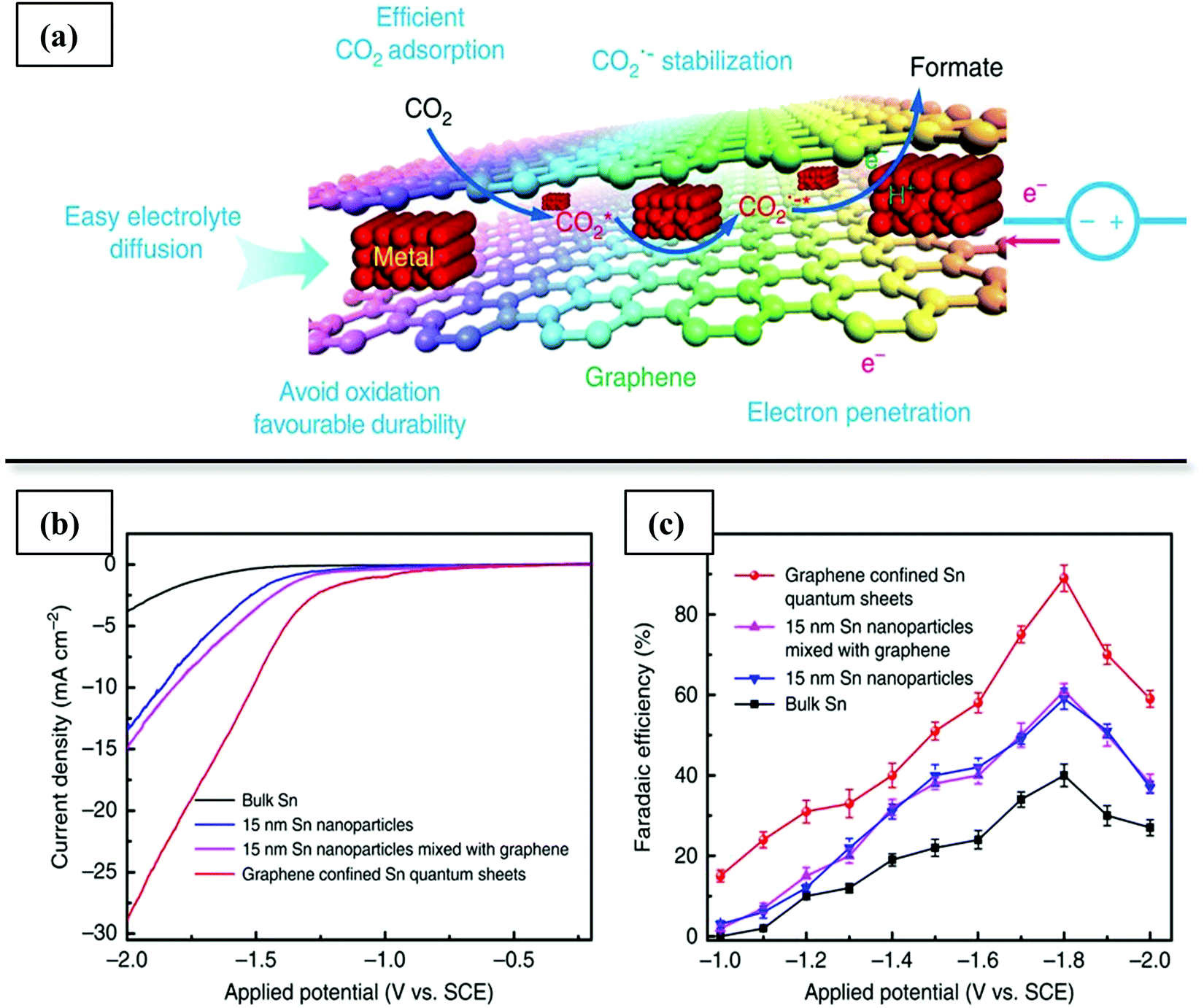 | ||
| Fig. 7 (a) Schematic illustration of the advantages of confinement of thin Sn layers between graphene nanosheets for CO2 electroreduction into hydrocarbons. (b) Linear sweep voltammetric curves in CO2-saturated 0.1 M NaHCO3 aqueous solution and (c) faradaic efficiencies for formate at various applied potentials of confined Sn in graphene and reference catalysts. Reproduced with permission from ref. 5. Copyright (2016) Springer Nature. | ||
So far, there have been only limited reports of core–shell electrocatalysts for formate-selective CO2 reduction (Table 5b). A rough comparison (keep in mind that reported performance can vary depending on experimental conditions, electrolyte, mass transfer and polarisation effects, electrode roughness factor, etc.) with some recently reported Sn and Co-containing non-core–shell catalysts shows encouraging performance of the core–shell catalysts in terms of formate partial current density at lower overpotentials (Table 6b).
3.3.2.3. Electrocatalytic CO2 reduction to hydrocarbons/oxygenates. The production of hydrocarbons and C2+ oxygenates in CO2 reduction involves multiple elementary steps and electron/proton transfers and requires high overpotentials for the further hydrogenation of the *CO intermediate. In contrast to the 2e− transfer production of CO and HCOO−, which can be achieved with ≥90% FE on several catalysts, few catalysts are capable of achieving such high selectivity for hydrocarbon or higher oxygenate production from CO2 reduction. Cu can give hydrocarbon and oxygenates beyond the 2e− reduction pathway but usually produces a broad mixture of products and requires high overpotentials. It is also difficult to suppress HER at the high overpotentials required for hydrogenation of the *CO intermediate. On Cu-containing catalysts, the protonation of *CO to *CHO is the potential-limiting step (Scheme 4), and on the monometallic Cu surface, the binding energies of these two intermediates scale in a way that does not allow optimisation of the activity. To reduce the overpotential requirement for CH4 or CH3OH formation, the adsorption of the *CHO intermediate on the catalyst has to be more favoured than that of *CO. It has been shown by DFT calculations that the surface strain of the Cu atoms affects the adsorption of *CO and *CHO in different ways, because these species have different bonding configurations. A stronger dependence of binding energy on surface strain is expected for *CHO and *COOH than for *CO, because the Cu–Cu distance directly affects the C–O bond in *CHO and *COOH. Hence, structural engineering of a Cu catalyst to increase the tensile surface strain can selectively increase the adsorption strength of the *CHO intermediate on Cu compared with *CO, leading to a lower overpotential requirement for methane formation.
Huang et al.221 proposed that introducing Au atoms with their greater atomic radius as the core material in Au@Cu core–shell structures would increase the tensile strain on the surface Cu atoms and lower the overpotential for CO2-RR to methane to −0.64 V (vs. RHE). Liu et al.40 conducted a DFT calculation for a core–shell type Cu–M (M = Ni, Co, Rh, Ir, Pt, Pd) heterostructure and concluded that the overpotential required for CO2 reduction can be lowered by 0.17 V on Cu (3 monolayers)–Ir catalyst relative to the value for Cu(111). The authors proposed that apart from the lattice strain effect of the core–shell structure, the ligand effect of the Ir substrate also had a significant effect on the adsorption energies of the key intermediates. Fe19@Cu60 has also been predicted to be a suitable low-cost transition metal to lower limiting overpotential for CO2-RR to methane.239 Bimetallic cores can provide more flexibility in tuning the electronic properties of the core–shell material than monometallic cores, and recent DFT calculations have predicted low overpotentials for 8 electron-proton CO2 reduction on bimetallic core@Cu materials resulting from optimisation of the position of the d-band centre of the shell to enhance the interaction with *CHO intermediate.240
From an economic point of view, the synthesis of C2+ alcohols or hydrocarbons is preferable to synthesis of methane by electrocatalytic CO2-RR. Pristine Cu shows a higher selectivity to methane than other C2+ hydrocarbons or oxygenates, and much effort has been directed to improving the selectivity for ethylene, ethanol, or higher alcohols. C2 synthesis from CO2-RR requires C–C coupling between neighbouring C-containing intermediates on the catalyst surface. Several mechanisms have been proposed for C–C coupling on Cu surfaces such as coupling between two *CH intermediates,241 between *CO and *CHO,242 or between two adsorbed *CO intermediates.215 Mechanistically, higher surface coverages by carbon-containing intermediates can increase the probability of C–C coupling. Au@Cu catalysts with various Cu shell thicknesses exhibited different selectivities to methane and ethylene, with the differences attributed to the change in lattice strain on the Cu.243 Thick Cu layers (14 monolayers) exhibited a behaviour similar to that of bulk Cu, with higher selectivity for methane. However, when the Cu thickness was reduced to 7–8 monolayers, C–C coupling was favoured, and ethylene became the main hydrocarbon product. It has been inferred on the basis of several DFT investigations that the lattice expansion of Cu on Au depends on the Cu layer thickness. It was proposed that the Cu d-band centre was increased in the Au@Cu with 7–8 Cu monolayers, resulting in stronger *CO adsorption and a higher probability of C–C coupling to form ethylene. Similarly, an Ag@Cu catalyst with optimum Ag/Cu ratio (Ag:Cu = 1:2.31) and Cu shell thickness (∼15 nm) was observed to produce ethylene at a higher selectivity than pure Cu or other compositions of Ag@Cu.230 The lattice mismatch between Ag and Cu increased the interatomic distance in Ag@Cu-20 relative to pure Cu, leading to a stronger adsorption of *CO and an increased probability of ethylene formation. The maximum FE for ethylene (29%) was also observed at a comparatively low overpotential of −1.06 V. The low overpotential requirement also lowered the H2 by-product formation by HER. A similar enhancement in ethylene: methane selectivity on extremely thin Cu overlayers has been reported for Cu on Pt substrate catalysts.244
C2+ alcohols are more valuable than ethylene from the viewpoint of transportability and energy density. The mechanisms of ethylene and ethanol production in CO2 electro-reduction are believed to share a common intermediate *CH2CHO, which can either be hydrogenated to form ethanol or lose an oxygen to the catalyst surface to form ethylene. On a pristine Cu surface, the activation energies for the first hydrogenation step of the *CH2CHO intermediate by the ethylene and ethanol formation pathways are 0.56 eV and 0.645 eV, respectively, at −0.5 V applied overpotential (vs. RHE), and ethylene is favoured over ethanol.
Relying on DFT modelling, Zhuang et al.245 predicted that a core–shell structure with Cu vacancies on a CuS core would selectively increase the activation energy barrier of ethylene to 1.148 eV, while keeping that of ethanol almost unchanged, with the net effect of increasing ethanol selectivity. The predictions were validated qualitatively by experiment as a six-fold ratio of alcohol to ethylene was achieved on the core–shell CuS@Cu–V (with Cu vacancies) compared with pristine Cu nanoparticles. The core–shell CuS@Cu-V catalyst was characterised by a high C2–C3 alcohol FE of 23% and 7.3 mA cm−2 partial current density at −0.95 V (vs. RHE). This work provides valuable insights into how theoretical predictions can be used to predict how to modulate the intermediate adsorption energies of species on core–shell interfaces and steer the CO2-RR products beyond alkenes to alcohols.
Another intriguing strategy for increasing alcohol selectivity in CO2-RR using core–shell catalysts was reported by Yang et al.246–248 In homogeneous CO2 electrocatalytic reduction, pyridine has been shown to be efficient as a homogeneous catalyst in producing methanol on Pt and on Pd catalysts. Thus, hybrid metal–organic composites containing pyridine derivatives entrapped within metals or bimetallic alloys were found to have high selectivities for methanol and ethanol in CO2 reduction (for example, 35% FE to methanol was observed for PYD@Pd at −0.6 V vs. SCE).248 These composite catalysts preserve the functionality of the pyridinic ring and selectivity for alcohol formation, while still having the benefits of ease of separation of products from solid catalysts.
The compilation of Table 5c gives an indication of the breadth of approaches to enhancing CO2-RR to C2+ products using core–shell heterostructures, showing that fairly high selectivities to ethylene and alcohols have been achieved compared with those observed for other types of copper catalysts (Table 6c). However, non-core–shell structured catalysts with higher values of FE to ethylene have also been reported, such as plasma-activated Cu that is rich in Cu(I) (nearly 60% ethylene selectivity).
Core–shell electrocatalysts for CO2-RR are still at an early stage of research, and there is significant opportunity for further improvement. Fundamental knowledge gained from a rich body of literature of conventional electrocatalysts, including effects of nanosizing, preferential faceting, metal oxidation state, lattice defects, and electrode roughness factors can serve as guidelines for further research in core–shell catalysts.
3.4. Core–shell catalysts for photocatalytic CO2 hydrogenation
Depending on the catalyst and reaction conditions, the products of CO2 photoreduction may include CO, methanol, CH4, or other hydrocarbons. The photocatalytic reduction of CO2 requires input of solar energy to break the CO bonds, which are more stable than the C–C or C–H bonds formed as a result of hydrogenation. Because CO2 is optically transparent to visible or UV light in the range of 200–900 nm, a photocatalyst with a suitable bandgap is required to absorb photons and generate electrons that can migrate to CO2 and carry out the reduction process. A semiconductor catalyst generates electron–hole pairs upon photoexcitation, which then separate and diffuse to the catalyst surface and cause redox reactions of water oxidation and CO2 reduction, with CO2 being reduced by the electrons (e−) and H2O being oxidised to O2 by the holes (h+) ((Scheme 5), eqn (22)–(28), E values vs. NHE (Normal Hydrogen Electrode), pH = 7).
| CO2 + 2e− + 2H+ → HCOOH E = −0.61 V | (22) |
| CO2 + 2e− + 2H+ → CO + H2O E = −0.53 V | (23) |
| CO2 + 4e− + 4H+ → HCHO + H2O E = −0.48 V | (24) |
| CO2 + 6e− + 6H+ → CH3OH + H2O E = −0.38 V | (25) |
| CO2 + 8e− + 8H+ → CH4 + H2O E = −0.24 V | (26) |
| 2e− + 2H− → H2 E = −0.41 V | (27) |
| 2H2O + 4h+ → O2 + 4H+ E = 0.82 V | (28) |
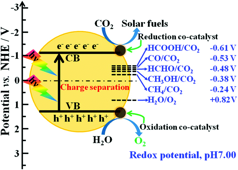 | ||
| Scheme 5 Schematic illustration of probable mechanism of photocatalytic CO2 conversion to solar fuels. Reprinted with permission from ref. 1. Copyright (2016) American Chemical Society. | ||
A suitable photocatalyst for CO2 reduction must have the following properties: (a) multiple electrons that can be photoexcited and transferred easily to CO2, (b) a conduction band edge more negative than the reduction potential of CO2 and its corresponding reduced products, (c) good absorbance of visible light, and (d) ability to adsorb the reactants (CO2, H2O, etc.). A wide variety of semiconductors, such as metal oxides (TiO2, Nb2O5, ZnO, ZrO2, Fe2O3, perovskites, etc.), metal sulfides (CdS, ZnS, etc.), polymeric carbon materials (g-C3N4, graphene), layered double hydroxides (LDH), SiC, and transition metal complexes have been investigated for photocatalytic hydrogenation of CO2.262 Anatase titanium oxide (TiO2) is commonly investigated for photocatalytic processes because of its bandgap value of approximately 3.2 eV, long-term photostability, environment-friendliness, and abundance.60,263,264
However, TiO2 is characterised by poor performance in visible light-irradiated photoreactions because its bandgap is greater than 3 eV (corresponding to visible light photon energy), and it can be excited only by UV radiation at wavelengths below 400 nm. Semiconductors with narrow bandgaps, which can be excited by visible light, are often poorly active for CO2 reduction by themselves, or lack stability. Another key issue in photocatalytic CO2 reduction is the rapid recombination of photogenerated electrons and holes before they can be transported to the surface to drive the redox reactions, which results in very low quantum efficiencies.
Re-oxidation of the products from CO2 reduction by photo-generated holes can also reduce the efficiency of the photo-reduction process. In a simple photocatalytic system, that utilizes a suspension of photocatalyst particles in a solvent for the reduction of dissolved CO2, both reduction and oxidation reactions occur on different sites of the same catalyst surface and the reduced products can be re-oxidized by the photo-generated holes or the produced oxygen. To reduce the occurrence of back-reactions, sacrificial hole scavengers such as Na2SO3, and H2O2 can be added to the reaction solution, and these become preferentially oxidized by the holes rather than CO2 reduction products; however, these components incurs added cost. To completely inhibit the problem of back-reactions, H-type photo-electrochemical cells (PEC) need to be adopted, so that the reduction and oxidation half-reactions occur separately in two half-cells separated by a proton exchange membrane.265 An external bias is required in this configuration.
Effective photo-reduction is also limited by weak interactions of the gas-phase CO2 with the solid photocatalysts, which usually have low CO2 adsorption capacities. Further, CO2 photo-reduction is a complicated process, involving several reaction pathways and control of product selectivity is essential. And the competing side reaction of water oxidation to form H2 needs to be suppressed to increase the CO2 reduction efficiency.
3.4.2.1. Enhanced charge separation. Recombination of photo-generated electrons and holes is one of the primary limitations contributing to low quantum efficiency in photocatalytic CO2 hydrogenation. Several approaches have been explored to increase the separation and migration of the photo-generated charges before they can recombine. The most prominent approach is heterostructure engineering of photocatalysts involving the integration of semiconductors with co-catalysts or the formation of heterojunctions with other suitable materials to facilitate charge transport.121,264,267 Heterostructures may be formed by decoration of one material with nanoparticles of a second material; however, such architectures have lower interface areas between the two materials and limited interactions. Core–shell architectures provide the prospect of precise, efficient means to create heterostructures between different materials with good control over the nature of the interfaces and maximization of interface area. In this section, we consider the application of core–shell nanomaterials for improving charge transport and separation in CO2 photo-reduction.
3.4.2.1.1. Formation of Heterojunctions. Heterojunctions may be formed between two semiconductors or semiconductor–metal or semiconductor-carbon to enhance interfacial charge separation. Depending on the band position of the constituent materials, semiconductor/semiconductor junctions may be type I (the conduction band (CB) and valence band (VB) of the narrower bandgap material falls between that of the larger bandgap material), type II (the CB and VB levels of the two semiconductors are staggered), or type III (the CB level of one semiconductor is lower than the VB level of the other).1 By choosing appropriate semiconductors with suitable band positions, the separation of the photo-generated charges can be improved. In a type II heterojunction, photogenerated electrons can be transported from one semiconductor to another with a more negative CB while holes migrate in the other direction, leading to good overall charge separation. For example, a CdS@CeO2 core–shell catalyst was reported to have a type II heterojunction formed at the interface of CdS and CeO2. The lower CB of CeO2 than of CdS induces a transfer of photoelectrons from CdS to CeO2 and an opposite transport of holes, preventing charge recombination. The composite CdS@CeO2 core–shell catalyst showed almost threefold higher yields of methanol and methane in CO2 hydrogenation than CdS under the influence of visible light.9
Thus, a core–shell structured catalyst can be used to enhance separation of photogenerated charges by introduction of heterojunctions with suitable materials and the base semiconductor photocatalyst in photochemical reduction of CO2.268 Core–shell structures are more favourable than normal heterojunctions to achieve high interfacial areas and close contact.94 Several core–shell structured composites of type II heterostructures of semiconductors have been reported for CO2 photoreduction.7,9,269,270 For example, hierarchical ZnO@Cu–Zn–Al LDH heterostructures were reported, wherein, the LDH nanosheets have a lower CB than ZnO and accept photogenerated electrons transferred from ZnO, while the holes generated in LDH migrate to ZnO.269 Good interfacial contact between the ZnO core and the LDH nanosheets allows fast transfer and separation of charges. The core–shell ZnO@Cu–Zn–Al LDH catalyst exhibited an enhanced photocatalytic activity for CO2 reduction (more than three times that of pure LDH) because of a combined effect of suppression of charge recombination and increased CO2 adsorption by the high-surface-area LDH structure.
To further enhance charge separation through heterojunction engineering, a more efficient sandwiched hierarchical ZnIn2S4–In2O3 catalyst with shells of 2D-ZnIn2S4 nanosheets coated on both sides of hollow In2O3 nanotubes was synthesized (Fig. 8).7 The design used 2D architecture for the exposed ZnIn2S4 nanosheets, which provides high surface area (for absorption and reaction) and reduces charge recombination because of the short diffusion path in the thin nanosheets, and integrated the photocatalytic functions of ZnIn2S4 and In2O3 in a hierarchical nanotube architecture with double hetero-junction shells with increased interfacial contact. By virtue of the higher charge separation rate and higher surface area for CO2 adsorption and reaction, the sandwich-like ZnIn2S4–In2O3 catalyst showed an impressive CO production rate of 3075 μmol g−1 h−1 in CO2 hydrogenation, four times higher than what was observed with a physical mixture of ZnIn2S4 and In2O3.
 | ||
| Fig. 8 Hierarchical sandwiched core–shell tubular hetero-structured photocatalyst for enhanced charge separation in photocatalytic CO2 reduction. (a) Sandwich-like hierarchical structure of ZnIn2S4–In2O3 catalyst and schematic representation of separation of photo-generated charges. (b) FESEM image of ZnIn2S4–In2O3. (c) CO2 photoreduction activities of sandwich-like ZnIn2S4–In2O3 with various compositions, In2O3 and ZnIn2S4 (d) Steady state photoluminescence (PL) spectra of ZnIn2S4–In2O3 and ZnIn2S4, showing suppressed charge recombination in the sandwich-like ZnIn2S4–In2O3 catalyst. Reprinted with permission from ref. 7. Copyright (2018) American Chemical Society. | ||
Charge separation can also be improved by the formation of p–n type hetero-junction formed between an n-type and p-type semiconductor. In a p–n heterojunction, a space-charge region is created at the interface, with positive charges accumulating in the n-type semiconductor and negative charges accumulating in the p-type semiconductor, and an electric field is induced. If the charge migration resulting from the band structure of the composite is in line with the direction of charge transport under this electric field, an overall enhancement of charge separation is achieved.271–274 Core–shell structured materials with p–n junctions have been reported for various photocatalytic applications such as hydrogen production, dye degradation, etc.271–273 Wang et al.272 reported a p–n junction TiO2@NiO2 hierarchical hollow shells, wherein an inner electric field was formed at the interface, pointing from n-type TiO2 to p-type NiO. The direction of charge transport forced by this electric field coincided with the charge transport associated with the traditional heterojunction between NiO and TiO2 because of the aligned band structure, which could drive electrons from the CB of NiO to that of TiO2, and holes from the VB of TiO2 to that of NiO. Thus, the p–n junction at the core–shell interface could further increase charge separation and achieve higher photoactivity. Tan et al.275 reported a raspberry-like-microsphere core–shell Cr2O3@TiO2 catalyst for photocatalytic CO2 hydrogenation, whereby a close contact of the p–n junction was achieved between Cr2O3 and TiO2, resulting in increased charge separation and a 2-fold increase in methane yield.
Carbon materials such as carbon nanotubes (CNT) and graphene can also improve charge separation efficiency by acting as electron sinks that can transfer away the photogenerated electrons. TiO2/carbon nanocomposites in core–shell structures have been reported to significantly improve photoactivity for CO2 reduction upon exposure to visible light.60,61,74,262,263 The transfer of electrons via the TiO2–carbon heterojunction reduces electron–hole recombination, and these charges can subsequently catalyse further reactions. Gui et al.263 reported a multi-walled carbon nanotube (MWCNT)@TiO2 photocatalyst for the photocatalytic reduction of CO2 to form methane upon exposure to visible light. Uniform TiO2 particles were coated onto the nanotubes to form an overlayer, and the composite showed much higher photocatalytic activity than anatase or multi-walled carbon nanotubes, with a methane yield of ca. 0.17 μmol gcat−1 h−1. The same group also investigated the effect of varying the TiO2 loading in MWCNT@TiO2 photocatalysts for CO2 reduction. Raman spectra of the core–shell catalyst showed a downshift of the G-band of the carbon nanotubes after the addition of a TiO2 layer, caused by a transfer of electrons from the neighbouring TiO2 crystals to the MWCNT. The radiative recombination rate of electron–hole pairs of these core–shell nanocomposites, measured by the peak intensities of photoluminescence (PL) spectra, significantly decreased with increasing MWCNT loading. The MWCNTs trap some of the electrons generated from the photoexcitation of the TiO2 shell and serve as a “bridge” to transfer the electrons from the TiO2 to adsorbed CO2 molecules. These phenomena lead to the reduction of the density of electrons trapped in the TiO2, eventually contributing to the inhibition of the electron–hole pair recombination. An optimum composition of TiO2/CNT = 1/0.24 was observed to maximise the CH4 yield to 1.1 mmol gTiO2−1 because of a combination of effects involving the TiO2 active sites and electron separation efficiency induced by the CNTs.60
Similarly, Zhao et al.74 synthesized a reduced graphene oxide (rGO) wrapped Pt/TiO2 core shell photocatalyst (Pt/TiO2@rGO) for photocatalytic conversion of CO2 to CH4. Pt nanoparticles deposited on TiO2 can rapidly transfer the excited electrons originating from TiO2, and a directional electron transfer from TiO2 → Pt → rGO was posited at the core(TiO2)–mediator(Pt)–shell(rGO) heterojunction, that could enhance the separation efficiency of photogenerated electrons and holes. Among a series of core–shell catalysts prepared with various rGO loadings, (Pt/TiO2)@rGO-2 (with a nominal mass ratio of rGO to Pt/TiO2 of 0.02) showed the highest photocatalytic activity and selectivity for CO2 conversion, with a CH4 formation rate of 41.3 μmol gcat−1 h−1 and a CH4 selectivity of 99.1%.
Such carbon/semiconductor nanocomposites have also been applied for non-TiO2-containing photocatalysts for CO2 reduction.262,268 For example, a ZnO-containing core–shell photocatalyst with the composition rGO@CuZnO@Fe3O4 was applied for photoreduction of CO2 to methanol and was characterised by almost four times the methanol yield observed with CuZnO@Fe3O4, because of enhanced electron movement and charge separation through the sp2 hybridised aromatic system in rGO. The presence of a Fe3O4 core also facilitated easy magnetic separation and recycling of the used catalysts.262
3.4.2.1.2. Photocatalyst/co-catalyst heterostructure. Addition of co-catalysts is a popular strategy to improve the efficiency of photocatalytic processes. Metal nanoparticles are commonly used as co-catalysts because they have a lower Fermi level than the semiconductor and allows a transport of photo-generated electrons from the semiconductor to the metal. The lowering of the overall Fermi level of the photocatalyst/co-catalyst composite makes it more reductive. Further, the metal/semiconductor hetero-junctions also increases charge separation efficiency by virtue of the formation of a Schottky barrier that allows one-sided transfer of photo-generated electrons from the semiconductor to the metal. The metal thus acts as an electron sink for photo-generated electrons and reduces the loss of photocatalytic activity by charge recombination. Noble metals such as Pt having a lower Fermi energy level can rapidly transport electrons from the semiconductor, and Pt/TiO2 composites are known for their effectiveness in CO2 reduction to methane, requiring 8 electrons (eqn (26)). Addition of metal co-catalysts (Pt, Pd, Ag, Au, Rh, etc.) has also been traditionally done by deposition of metal nanoparticles on semiconductors. However, such nanoparticles can suffer from corrosion, leaching, or agglomeration over time in photocatalytic reactions.264
Core–shell structured metal@semiconductor composites such as M@TiO2 (M = Au, Ag, Pt) have been widely reported for various photocatalytic applications to mitigate these issues and improve charge separation.266,276,277 Good stability and re-usability of such M@TiO2 core–shell structures under photocatalytic conditions have been reported.278 However, so far, only a few reports of such metal@semiconductor composite catalysts for photochemical CO2 reduction have emerged.279,280 Pougin et al.279 reported an Au@TiO2 catalyst with higher photocatalytic activity for CO2 reduction than Au/TiO2. It was noted, however, that further deposition of Au nanoparticles on the Au@TiO2 core–shell structure increased the methane production rate threefold, suggesting that the exposed Au/TiO2 interface (i.e., that of Au nanoparticles on the outer surface of TiO2) may be more effective in the reduction of CO2 to CH4 and CO than the encapsulated Au/TiO2 interface.
Multi-component co-catalysts can be assembled into core–shell configurations to improve the directional movement of electrons and improve charge separation. In such core–shell co-catalyst/semiconductor composites, transfer of photo-generated electrons occurs from the semiconductor → core → shell. Lee et al.281 investigated an NiO co-catalyst on InNbO4 (which is visible light active for CO2 reduction) and observed that the evolution of a Ni@NiO structure by a pre-treatment of the co-catalyst resulted in increased charge separation and improved methanol production from CO2 hydrogenation. The metallic Ni core acted as a bias for electron transfer from InNbO4 to the NiO layer, facilitating rapid electron migration to the surface to reduce CO2. Similarly, Ni@NiO loaded onto N-doped InTaO4 enhanced extraction of photo-generated electrons and subsequent methanol production from CO2 photo-reduction, with a three-fold enhancement over that of non-loaded samples.282 Transfer of photogenerated electrons from InNbO4 to NiO is hindered by the higher CB level on NiO than on InNbO4, and the addition of the metallic Ni core in the Ni@NiO composite allows faster extraction of electrons and transfer to the NiO layer. Han et al.283 explored the effect of Ni@NiO co-catalyst on graphite-phase carbon nitride (g-C3N4) for CO2 reduction and showed an increase in the rate of charge separation characterised by time-resolved fluorescence decay spectra. A nine-fold increase in CO production was obtained on the Ni@NiO/g-C3N4 catalyst compared with g-C3N4, with more than 87% CO selectivity from CO2 photo-reduction. In another investigation, Pt@Cu2O was loaded as a co-catalyst onto TiO2, which showed a 28-fold improvement in CH4 production compared with TiO2 and three times that of Pt/TiO2.8 The Pt@Cu2O core–shell structure helped in enhancing electron transfer from TiO2 while suppressing the hydrogen evolution side-reaction on the Pt surface (discussed in Section 3.4.2.4). Pt@CdS was also used as a selective co-catalyst with TiO2, with a vectorial electron transfer from TiO2 → Pt → CdS.284
Co-catalysts can also be used for the oxidative half-reaction (eqn (28)), acting as sinks for the photo-generated holes. Oxides such as CoOx, MnOx, and IrOx show good hole-accepting properties in the oxidative half reaction for water splitting and are also applicable in CO2 reduction with water.36 Co-loading of separate reduction and oxidation co-catalysts can make charge separation more efficient, as the various co-catalysts can trap electrons and holes separately. Core–shell structures are among the most effective for co-loading various co-catalysts, as the separate materials can be precisely deposited to keep them spatially separated while operating synergistically.
Oxidation and reduction co-catalysts have been deposited on opposite walls of hollow semiconductor shells. For example, CuPt nanoparticles (a reduction co-catalyst) and MnOx nanoparticles (an oxidation co-catalyst) were loaded onto inner and outer shells of hollow TiO2 spheres for photo-reduction of CO2.285 This configuration of electron and hole acceptors on opposite sides of the semiconductor shell caused the movement of the photo-generated charges in opposite directions, resulting in high charge separation efficiency and high CO evolution rates on the PtCu/TiO2/MnOx catalyst, with an overall solar energy conversion yield of 0.108%. Dong et al.286 also deposited Pt and CoOx on the outer and inner surfaces of hierarchically ordered porous TiO2–SiO2 (HTSO) frameworks and showed that the separated co-catalysts were characterised by a much higher methane formation rate (9.3 μmol g−1 h−1) from CO2 photoreduction in the presence of water vapour than randomly deposited Pt–CoOx on HTSO (0.61 μmol g−1 h−1). The random deposition of the Pt and CoOx co-catalysts can result in contact interfaces between Pt and CoOx that act as rapid electron–hole combination centres that reduce the overall photon efficiency. Zhu et al.287 reported a hollow CoO@TiO2@Au with spatially separated dual co-catalysts, which demonstrated 60 times higher photocatalytic activity for CO2 reduction than the parent TiO2.
Thus, hollow multi-core@shell structures of the form A@S@B (S is a semiconductor and A and B are co-catalysts) may find applications in enhancing the charge separation and overall efficiency of photocatalytic CO2 hydrogenation. Although this kind of cocatalyst-separated structure is effective for charge separation, the influence range of separated cocatalysts is limited to zones near the surface. To overcome this limitation, researchers combined the effects of a heterojunction and separation of cocatalysts in yolk–shell structures. Li et al.288 synthesized Pt@TiO2@In2O3@MnOx yolk@shell catalysts with thin hollow shells composed of TiO2@In2O3 heterojunctions and spatially separated Pt and MnOx as reduction and oxidation cocatalysts. The thin heterojunction shell could separate charges in the bulk phase and enable their transfer to the surface/subsurface region, where the cocatalysts on opposite surfaces of the shell could drive the charges in opposite directions. It was shown by time resolved PL spectroscopy data that the resultant diffusion lengths of charges in shells under these conditions of the synergistic effects was equal to or greater than the thicknesses of the shells, resulting in efficient charge separation.
Although the issue of electron–hole recombination has been investigated extensively for core–shell catalysts, the issue of back-reactions and re-oxidation of the reduced products on the oxidation sites of the photo-catalyst has drawn much less attention. One reason for the lack could be that a majority of the investigations so far have been conducted at low CO2 conversions or with large excesses of water, thus limiting the product concentration to low levels. Some investigators have employed sacrificial hole scavengers to suppress product re-oxidation on core–shell catalysts.285,289 For example, photocatalytic CO2 reduction on hollow TiO2-containing catalysts has been conducted in the presence of Na2SO3 solvent. SO32− is more easily oxidized than the CO product; thus, the photogenerated holes are more likely to be consumed by SO32−, and CO can be protected from re-oxidation.
Conceptually, core–shell structures with spatially separated oxidation and reduction co-catalysts (A@S@B where, S is a semiconductor and A and B are co-catalysts) may be able to suppress back-reactions more than photo-catalysts with randomly distributed oxidation and reduction co-catalysts.285,290 For example, hollow TiO2 shells with reduction and oxidation co-catalysts deposited on opposite surfaces will induce transport and accumulation of electrons and holes in the corresponding co-catalysts. If the catalyst structure can be designed in a way to suppress the access of CO2-reduction product to the surface where the oxidation co-catalyst is loaded, the probability of re-oxidation of the products can be reduced. Li et al.285 developed hollow TiO2 spheres with MnOx loaded on the inner surface and CuPt nanoparticles loaded on the outer surface. They proposed that CO2 reduction occurs on the reductive outer surface of the hollow catalyst, with the photogenerated holes migrating toward the inner surface because of the presence of MnOx. Mass transport limitations for the product molecules through the TiO2 shell were proposed to be significant and to suppress the re-oxidation of the products. Indeed, it was observed that a simple reversal of the sequence of co-catalysts from MnOx(inner)@TiO2@CuPt(outer) to CuPt(inner)@TiO2@MnOx(outer) resulted in a significant drop in product CO yield, although it is not apparent whether this was caused by back-reaction or by hindered mass transport of CO2 though the TiO2 shell to the CuPt surface. More rigorous analysis and optimization of the catalyst structure and transport rates of various molecules are required to fully understand the potential of such hollow structures with spatially separated co-catalysts in suppressing back-reactions in CO2 photo-reduction.
3.4.2.2. Enhanced visible light absorption. Semiconductors used for photocatalytic CO2 reduction, such as TiO2 and ZnO, usually have large bandgaps (>3 eV) and limited activity under the action of visible light. Two principal means of increasing photoexcitation with visible light are bandgap engineering of the semiconductors (by doping with suitable elements or combining with other materials) or integration of the semiconductors with light-responsive plasmonic materials. For both these strategies, effective interaction between the separate materials is crucial—and core–shell structures are highly appropriate. Yolk–shell catalysts can improve light absorption through multiple scattering in the hollow structure.
3.4.2.2.1. Bandgap engineering. To increase the visible light activity of the commonly used wide bandgap semiconductors such as TiO2, these semiconductors can be coupled with narrow-bandgap semiconductors, which can be excited by visible light and then inject the photo-generated electrons into the conduction band of the contacting higher-bandgap semiconductor. Assembly of these separate materials can be done efficiently in core–shell structures to optimise interaction and synergy. CdS is a commonly used semiconductor with a low band gap that can be used to boost the visible light activity of the photocatalyst. Ijaz et al.9 reported a CdS@CeO2 core–shell catalyst for photocatalytic CO2 reduction under the influence of visible light, which showed remarkably high light absorption because of the presence of CdS. CdS has a lower bandgap (2.3 eV) than CeO2 (3.4 eV), which is active only in the UV region (Fig. 9). Similarly, it was observed that in a Pt@CdS/TiO2 catalyst, the visible light absorption was enhanced because of the light trapping action of CdS, and the band gap of the composite core–shell catalyst decreased monotonically with increasing CdS content, accompanied by an increase in absorption in the 400–600 nm region.284
 | ||
| Fig. 9 Bandgap engineering in CdS@CeO2 core–shell composite to enhance visible light-driven CO2 hydrogenation: (a) schematic diagram of alignment of energy levels of CdS and CeO2. (b) CH3OH yield from CO2 photoreduction under the action of visible light with CdS, CeO2, and CdS@CeO2 core–shell catalysts. (c–e) UV/vis absorption spectra of CdS, CeO2, and CdS@CeO2. CdS acts as a photosensitizer that shifts the response of the catalyst from UV to visible light. Reprinted from ref. 9, Copyright (2018), with permission from Elsevier. | ||
Carbon-containing materials such as CNT and graphene can also act as photosensitizers enabling activation of TiO2 in reactions with visible light.74,263,291 Black carbon materials have good optical properties and can absorb radiation in the entire visible light range. MWCNT@TiO2 core–shell catalysts showed much higher photocatalytic activity for CO2 reduction than anatase when exposed to visible light.263 UV-vis data showed that the absorption edge of the MWCNT@TiO2 composite was extended to the visible light region (400–800 nm) by virtue of the optical properties of the carbon nanotubes, whereas the anatase was characterized by only poor absorbance at frequencies ≥400 nm. Similarly, wrapping reduced graphene oxide sheets around Pt/TiO2 led to an enhancement in visible light absorption efficiency.74
Core–shell structured coloured TiO2 catalysts with amorphous partially reduced TiO2−x shells and crystalline TiO2 cores also exhibited enhanced visible light absorption capacity. Surface reduction of TiO2 nanocrystals led to the formation of highly disordered surface layers with the formation of oxygen vacancies. TiO2−x with oxygen vacancies requires lower energy to excite electrons from the VB to the CB than TiO2. This lower band gap of the resultant TiO2−x causes a strong absorption in the visible and infrared regions, accompanied by a marked colour change from white to core–shell structured blue or black TiO2. Yin et al. reported TiO2@TiO2−x black TiO2292 and blue TiO2,293 that showed much higher visible light absorption by virtue of the lower bandgap, higher charge separation attributed to the TiO2/TiO2−x heterojunction, and higher CO2 photoreduction capacity to give CH4. A disordered H-TiO2−x shell was formed on TiO2 by a solvothermal method using various concentrations of lithium dissolved in ethanediamine.293 The formation of the disordered shell resulting from the Li-assisted surface reduction led to a change in colour of the TiO2 from white to blue and a significant increase in visible light absorption. However, too-thick a disordered layer was found to be unfavourable for the separation and transport of photo-generated carriers, and, hence, an optimum TiO2−x shell thickness was found to achieve the highest methane yield in CO2 photoreduction. Oxygen vacancies created in the partially reduced TiO2−x amorphous shell may also act as electron–hole recombination centres, reducing the photocatalytic activity. Lin et al.294 demonstrated that doping of non-metals such as H, N, S, and I into the amorphous TiO2−x shell of black TiO2@TiO2−x structures can fill these oxygen vacancies and reduce electron–hole recombination, while also improving solar energy absorption.
3.4.2.2.2. Integration with plasmonic materials. The addition of visible-light-responsive metals can also markedly increase visible light absorption by introducing impurity states. Noble metals such as Au, Rh, and Ag are able to extend the light harvesting capacity of TiO2 with localised surface plasmon resonance (LSPR) absorbance.295,296 The interaction of metals such as Au, Ag, and Pd with visible light causes a surface plasmon resonance (SPR), which is the collective coherent oscillation of metal conduction band electrons against the restoring force of the positive nuclei. The presence of such plasmonic metal nanoparticles can extend optical absorption to the visible light region by exciting SPR and injecting plasmonic-excited electrons into an adjacent semiconductor.297 Local surface plasmon resonance in the metal nanoparticles induces a spatially non-homogeneous electromagnetic field near the metal nanoparticle surface which facilitates the generation of electron–hole pairs in the nearby semiconductor under the influence of light irradiation. Core–shell Au@TiO2,279 yolk@shell Au@hollow TiO2,298 TiO2 nanowires@Ag nanoparticles,299 Ag-MWCNT@TiO2,300 and others have been reported to strongly improve photocatalytic reduction of CO2 by increasing the light absorption by the SPR effect.
Zou et al.298 synthesized Au@TiO2 yolk@shell hollow structures and showed that the local electromagnetic field arising from the LPSR effect led to a much higher photon absorption rate (proportional to the square of the electric field) and hence a much higher rate of generation and separation of electron–hole pairs in the TiO2 shell. The Au@TiO2 yolk–shell sphere showed significant enhancement in photocurrent response over bare TiO2 hollow spheres under the action of UV-visible light irradiation. The increased generation of electron–hole pairs attributed to the presence of Au not only increased the photocatalytic reduction of CO2 but also increased the selectivity to C2H6 by facilitating chemical reactions involving multiple e−/H+ transfer processes. The LPSR effect of these noble metal nanoparticles can be enhanced by increasing the size of the nanoparticles and the dielectric constant of the medium surrounding the nanoparticles. Coating a thin layer of dielectric material such as SiO2 or Al2O3 can increase the LPSR effect of the plasmonic nanoparticles, inducing higher photocatalytic efficiency under the influence of visible light. Bera et al.44 compared CO2 reduction on Au-loaded and core–shell Au@SiO2-loaded Pt/TiO2 catalysts, finding that the Pt/TiO2/Au@SiO2 catalyst had greater CH4 production than Pt/TiO2/Au, evidently as a consequence of the improvement in LPSR by the core–shell Au@SiO2 nanoparticles. A Pt nanodot and TiO2 coated Au nanoparticle catalyst with a core–satellite structure was recently reported to enhance photocatalytic CO2 reduction to formic acid and methanol (Fig. 10).4 The presence of Pt and TiO2 coating on the plasmonic Au nanoparticles helped to avoid ultrafast relaxation of plasmon-excited hot electrons by facilitating the rapid transfer from the Au core to the Pt nanodots. The TiO2 coating on the Au nanoparticles simultaneously broadened the plasmon resonance band towards near infra-red region and increased the strength of the LPSR induced electric field.
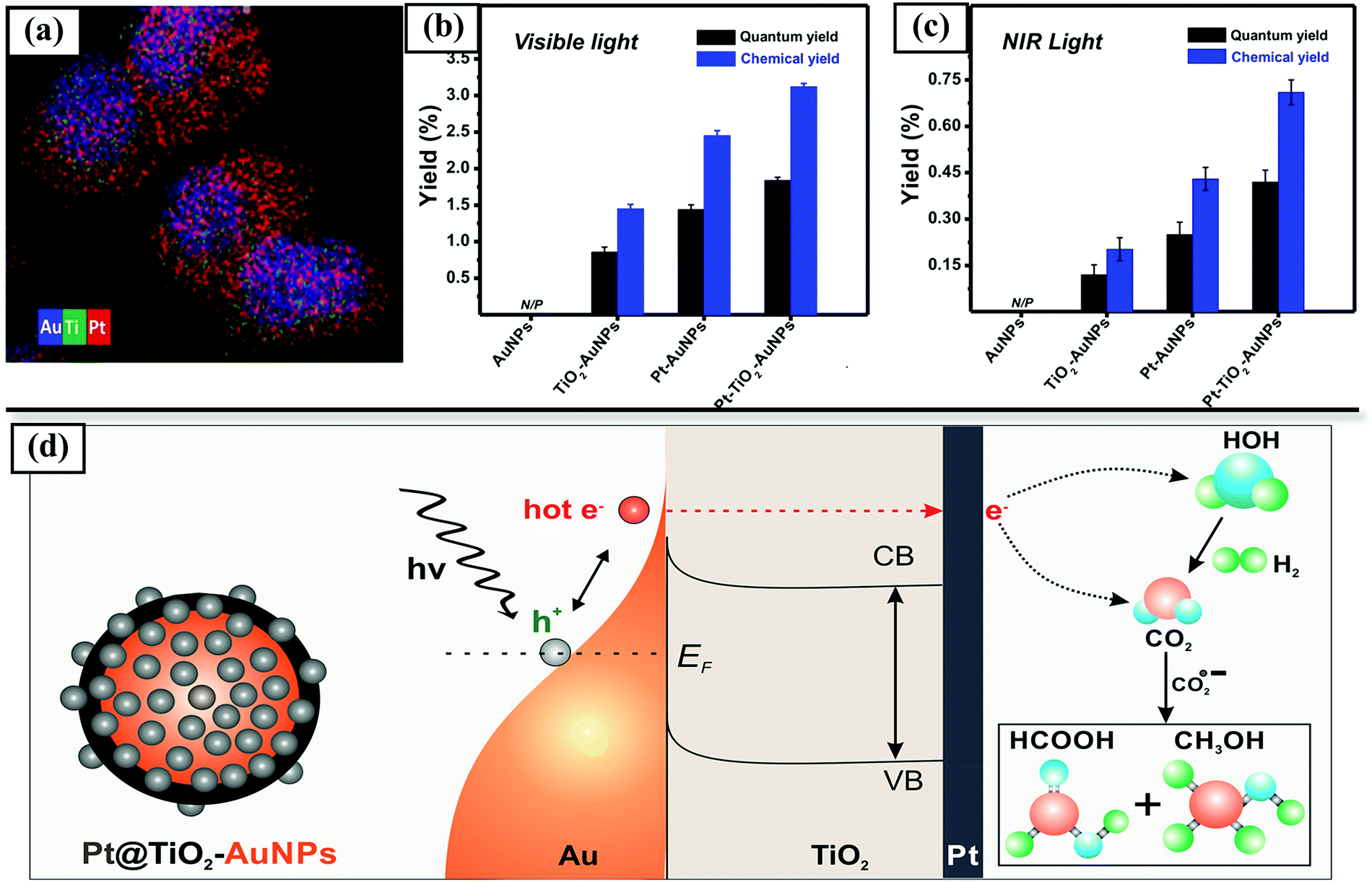 | ||
| Fig. 10 CO2 photoreduction on core–satellite plasmonic Pt@TiO2–Au nanoparticle catalysts:(a) EDX mapping image of Pt@TiO2–AuNPs. (b and c) CO2 photoreduction on various plasmonic hybrid nanostructures under the influence of visible light (Xe lamp) and NIR (808 nm) laser respectively. (d) Schematic representation of Pt@TiO2–Au nanoparticles-mediated CO2 reduction into HCOOH and CH3OH under the influence of light Irradiation. Reprinted with permission from ref. 4. Copyright (2018) American Chemical Society. | ||
3.4.2.2.3. Enhancement of scattering. Yolk@shell structures contain void spaces that can extend the path of light scattering within the photocatalyst and thereby further enhance the light absorption. Compared with solid particles that rely only on the direct irradiation to excite charges, a hollow structure allows multiple reflection and scattering of incident light inside shells, thus prolonging the path of light to enhance its absorption.301–306 Various configurations of yolk–shell or hollow structures can be used for harvesting and utilization of scattered light. The core may be photo-catalytically active with inert shells (for example, TiO2@SiO2) to limit light in the hollow cavity by reflecting and scattering.307 Alternately, shells can be synthesized with photo-active materials, and inert cores with high reflectivity can be used to reflect light to the shell. This is exemplified by SiO2@Pt–TiO2, with an inert SiO2 core to reflect light to a hollow TiO2 shell and Pt nanoparticles dispersed in the void to work as cocatalysts.308 Both cores and shells can also be made of photo-active materials, so that light scattering between the core and shell synergistically increases photo-generation of charges309,310 The hollow shells may be composed of single photo-active materials or heterojunctions between more than one material.311–314 For example, hollow CdS spheres coated with monolayer N-doped graphene were reported for CO2 photo-reduction to CO and CH4, wherein the hollow cavity was used to act as a photon trap, and the core–shell layered structure provided a close interfacial contact between CdS and graphene, endowing the hollow core–shell composite with more than three-fold higher CO2 reduction activity than conventional CdS/graphene composites.311 Several such hollow structured composites including hollow g-C3N4@CeO2,315 TiO2@In2O3316 and nanotubular C–Cu2−xS@g-C3N4,317 among others that have been reported in the preceding few years for photo-CO2 conversion.
To further enhance light scattering, double or multiple shelled hollow structures have been constructed, so that the incident light can keep scattering not only in the inner void but also in between the shells.318–320 Zou et al.318 reported a multi-layered hollow titania@graphene catalyst with alternating TiO2 and graphene for CO2 hydrogenation, whereby the hollow multi-layered structure acted as a photon trap-well through multi-scattering of the incident light. The beneficial effect of multiple shells in hollow structures was demonstrated by Wang et al.319 using MOF-derived hollow multi-shelled Co3O4 dodecahedra. Increasing the number of shells from 2 to 4 in hollow Co3O4 dodecahedra resulted in a two-fold increase in CO yield in CO2 hydrogenation, reaching a CO STY of 46.3 μmol g−1 h−1.
Yolk–shell and hollow photocatalysts incorporating separate kinds of semiconductors, plasmonic metals, carbon materials, etc. have also been applied widely for solar light scattering and harvesting in photocatalytic applications such as water splitting and photo-decomposition of alcohols and dyes.302 Architectures ranging from traditional yolk@shell309,310 to multi-shelled,321,322 double-yolk@shell,323 ordered hierarchical assemblies of hollow or yolk@shell spheres,324 and others have been reported to enhance light absorption. Further catalyst exploration in this regard using such advanced architectures and material compositions for photocatalytic CO2 hydrogenation are expected to be of continuing interest.
3.4.2.2.4. Photon upconversion. Photon upconversion is a process of emission of light with a shorter wavelength than that of the excitation light.325–327 In photocatalysis, upconversion materials can shorten the wavelength of incident light so that semiconductors with relatively large band gaps can be excited by the converted light with a shorter wavelength, thus allowing the utilization of lower energy radiations like visible or infrared light. Materials containing rare earth ions, doped fluorides, oxides, sulphur-containing compounds, etc. or semiconductor quantum dots such as NaYF4, LiYF4, NaGdF4, CaF2, Gd2O3, CdSe, and PbS can act as upconversion materials.306
Core–shell structures provide suitable platforms for use of upconversion nanoparticles for photocatalytic applications. For example, a core–shell structure was constructed with an upconversion nanoparticle (NaYF4:Yb/Tm@NaYF4:Yb/Er) core encapsulated in a photocatalytic shell of ZnxCd1−xS for photodegradation.327 ZnxCd1−xS can be excited by visible light but cannot absorb near-infrared photons. With the core–shell structure, near-infrared radiation in the incident light could be transformed to visible light by the upconversion material core, and then used to generate charges by the photoactive shell, leading to an overall improvement in solar energy utilization.
Although photon upconversion materials have been applied in photocatalytic CO2 hydrogenation,328 there are barely any investigations so far employing core–shell architectures in this application.
3.4.2.3. Enhanced CO2 absorption. Apart from the more prominent effects of charge separation and visible light absorption, core–shell catalysts can also be used to boost CO2 conversion by increasing the CO2 adsorption capacity of the photocatalyst. The adsorption and surface reaction of CO2 are crucial for its photoreduction. CO2 has a low propensity for chemisorption and surface reaction with photogenerated charges because of its stability and inert, non-polar nature. In the photoreduction of CO2 with water, water is adsorbed on the photocatalyst more strongly than CO2, making the hydrogen evolution reaction (HER) from water a significant side reaction. Chang et al.265 emphasized the need for enhanced CO2 adsorption and activation to suppress the competing HER and increase the efficiency of CO2 photo-reduction.
Ordered microporous materials such as MOFs have high capacities for adsorption and storage of gases. Core–shell structures integrating semiconductors with such CO2 adsorbing materials have shown enhancement in CO2 photoreduction yields. Li et al.10 reported a Cu3(BTC)2@TiO2 core–shell catalyst with a Cu3(BTC)2 MOF core (BTC = benzene-1,3,5-tricarboxylate) having a high CO2 adsorption capacity and a mesoporous TiO2 shell that allowed the transport and capture of reactant CO2 molecules in the core (Fig. 11). Ultrafast spectroscopy experiments showed that the light-induced electrons could be effectively transferred from TiO2 to the MOF, which, upon injection of one or two electron charges, can turn into an active catalytic material for CO2 activation. A ZIF-8/TiO2 core–shell catalyst has been reported with a ZIF-8 shell, which provides a very high surface area for CO2 adsorption. The presence of the ZIF-8 shell also increased the selectivity for CO formation, suppressing CH4 formation by virtue of the size-selective nature of the microporous shell. The ZIF-8/TiO2 core–shell catalyst exhibited a higher CO yield than TiO2 in CO2 hydrogenation, and, more important, markedly increased the stability of the catalyst.93 Other carbon materials such as reduced graphene oxide (rGO) can also improve CO2 adsorption when used as shells. Improved CO2 adsorption was observed on wrapping a rGO shell on Pt/TiO2, owing to the surface residual hydroxyl groups and high π electron cloud on the rGO sheets.74 A TiO2@SiO2 catalyst with a mesoporous silica shell was also shown to exhibit high photocatalytic conversion of CO2 to CO by artificial photosynthesis, because of the higher CO2 adsorption capacity in the core–shell catalyst conferred by the higher specific surface area and porosity of the shell.329 Other approaches to improving CO2 adsorption in core–shell structures include the use of high-surface-area geometries (such as nano-sheets) in the exposed shells.7,269,270
 | ||
| Fig. 11 Enhanced CO2 sorption and photocatalytic CO2 hydrogenation performance on core–shell Cu3(BTC)2@TiO2: (a) structural illustration and (b) TEM of Cu3(BTC)2@TiO2 core–shell structures, (c) CO2 adsorption behaviour for Cu3(BTC)2@TiO2 core–shell structures and bare Cu3(BTC)2, (d) production yields of CH4 and H2 from CO2 using Cu3(BTC)2@TiO2 core–shell structures as photocatalysts under UV irradiation. Reproduced with permission from ref. 10. Copyright (2014), Wiley. | ||
3.4.2.4. Enhanced selectivity. During photoreduction of CO2 with water, a competing side-reaction that reduces the efficiency of the process is the co-production of H2 from the reduction of H+ (eqn (27)). The consumption of photo-generated charges in the reduction of H+ reduces the number of electrons participating in CO2 reduction and lowers the yield. Addition of noble metal co-catalysts to semiconductors such as TiO2 increases the photocatalytic activity by trapping the electrons, but also markedly increases the production of H2 in the reaction, lowering the selectivity for CO2 reduction products including CH4, CO, and methanol. Investigating such phenomena, Zhai et al.8 prepared a Pt@CuO/TiO2 photocatalyst that exhibited high (>85%) selectivity for CO2 reduction and suppression of H2 formation, while also significantly enhancing photocatalytic activity. Adding Pt nanoparticles to TiO2 was observed to increase the photocurrent, with some improvement in methane yield—but with a loss of CO2 reduction selectivity and a significant increase in H2 formation. Addition of a Cu2O shell surrounding the Pt sharply suppressed H2 formation and increased the methane yield to 28 times that characterizing TiO2 and three times that characterising Pt/TiO2. It was proposed that the deposition of a Cu2O shell on Pt prevents the reduction of H2O to H2 on Pt sites and provides sites for the preferential activation and conversion of CO2. A Pt–Cu/TiO2 catalyst with separate Pt and Cu oxide particles dispersed on TiO2 did not achieve this increase in selectivity, showing the importance of the core–shell structure.
On the basis of a similar concept, several other core–shell catalysts have been investigated and have shown promising potential in increasing selectivity for CO2 reduction products.74,280,284 Coating materials such as rGO,74 CdS,284 and Ag280 that are more selective for CO2 hydrogenation, albeit with lower activity, on the noble metal co-catalysts help to achieve high overall photocurrent with lower H2 production. A Pt@CdS/TiO2 catalyst exhibited >90% selectivity for CO2 reduction, a marked increase over the 40% selectivity observed for Pt/TiO2 under the same conditions (Fig. 12).284 CdS is a selective co-catalyst for the reduction of CO2, and the core–shell Pt@CdS structure causes a vectorial electron transfer from TiO2 → Pt → CdS, increasing the electron density in CdS and increasing the conversion to CH4, which requires 8 electrons (eqn (26)).
 | ||
| Fig. 12 Enhanced selectivity to photocatalytic CO2 reduction over core–shell-structured Pt@Cu2O loaded TiO2: (a) schematic representation of photocatalysis mechanism, (b) dependence of CO2 reduction selectivity and yield on the content of Cu overlayer in the Pt@Cu2O loaded TiO2 catalysts under visible light. Reproduced with permission from ref. 8. Copyright (2013), Wiley. | ||
CO2 photoreduction may also yield various products, mainly CO, CH4, and methanol. The selectivity to any of these is governed by multiple properties, such as the band positions of the photocatalyst, the rate of generation and transport of electrons to the reaction sites, the nature of catalytic sites, and the reaction conditions. To reduce CO2 to a particular product, such as methanol, the position of semiconductor CB should be more negative than the reduction potential of CO2/CH3OH (−0.38 V vs. NHE at pH 7) and the position of VB should be more positive than the oxidation potential of H2O/O2 (+0.82 V vs. NHE at pH 7). The number of electrons required for CO2 reduction is also different for different products; CO formation needs only 2 electrons whereas methane and methanol require 8 and 6 electrons respectively. As discussed in the preceding sections, core–shell structures provide a broad playing field for efficiently combining materials with distinctive properties and tuning the band structure, the charge transport or the addition of co-catalysts to the semiconductors. Thus, in principle, there is broad scope in applying core–shell materials to tune the selectivity of CO2 photoreduction to a certain product, and some of the investigations mentioned above have led to clearly observed changes or enhancements in product selectivity.93,284,298,329 However, until now, there have not been many investigations carried out with the aim of specifically tuning the product selectivity by using core–shell structures in CO2 photo-reduction—this, we infer, is a potentially valuable research direction.
Overall, core–shell structured photocatalysts can achieve the synergistic operation of electron conductors/mediators, photosensitizers and CO2 adsorbents and activators. Some ingenious material designs have been able to incorporate all these functionalities in a single structure, leading to considerably improved performance in CO2 photoreduction to CO. For example, Wang et al.320 developed a hierarchical N-doped carbon@NiCo2O4 double-shelled hollow nanobox catalyst that combined the activity of Ni and Co species with conductive N-doped carbon in a 3D hollow structure to achieve high charge separation efficiency, CO2 adsorption capacity, and more active sites for photochemical conversion of CO2. The hollow structure with an interior cavity (a) favoured charge separation by facilitating transport from bulk to surface, (b) increased surface area for CO2 adsorption, and (c) enhanced light absorption by multiple scattering/reflection in the hollow cavity. The mixed Co–Ni oxide nanosheet inner layer accelerated charge migration rates and surface reaction while the N-doped carbon shell provided enhanced light harvesting properties. Titania@graphene multi-layered hollow nanospheres were reported, consisting of alternate Ti0.91O2 and graphene nanosheets.318 Here also, the ultrathin sheet structure of titania was taken advantage of to accelerate charge diffusion to the surface, which in combination with the electron-accepting nature of graphene increased charge lifetime. The hollow structure acted as a photon-trap to increase visible light absorption by multiple scattering. The Ti0.91O2@graphene hollow spheres exhibited nine times higher photocatalytic activity for CO2 reduction than anatase TiO2.
Furthermore, another benefit of using core–shell structured photocatalysts is to reduce the deactivation of the catalyst resulting from photo-corrosion of semiconductors. For example, CdS is suitable for excitation under the influence of visible light because of its narrow bandgap, but its long-term stability is limited. A CdS@CeO2 catalyst showed higher stability in the conversion of CO2 to methane and methanol under the action of visible light than pristine CdS, which underwent photo-corrosion causing changes in its morphology.9 Similarly, a graphene coating on Cu2O was observed to suppress Cu leaching during photo-reduction of CO2.330
Table 7 is a summary of recent work on core–shell photocatalysts for CO2 reduction. A comparison with some state-of-the-art supported catalysts for photocatalytic CO2 hydrogenation using water as a reducing agent (Table 8) indicates significant improvement in performance associated with core–shell structures, both in terms of product yield, selectivity to CO2 reduction products (suppression of hydrogen evolution), and overall solar energy-to-fuel conversion efficiency.
| Photocatalytic CO2 hydrogenation | |||||||||||
|---|---|---|---|---|---|---|---|---|---|---|---|
| No. | Catalyst | Synthesis method | Light source and power | System | Major product | Selectivity (%) | Product yield (μmol g−1 h−1) | Time on stream (h) | AQYc | Remarks | Ref. |
| a Selectivity of desired product among CO2 reduction products, calculated on an electron basis; for example, selectivity (CO) = [2n(CO)]/[2n(CO) + 8n(CH4) + 6n(CH3OH)] × 100%. b Overall selectivity of CO2 reduction products, calculated on an electron basis = [2n(CO) + 8n(CH4) + 6n(CH3OH)]/[2n(CO) + 8n(CH4) + 6n(CH3OH) + 2n(H2)] × 100%. c AQY, Apparent Quantum yield = (number of reacted electrons/number of incident photons) × 100%. d Overall conversion yield = [R(CO) × ΔG°]/[P × S] × 100%, where R(CO), G°, P, and S denote rate of CO evolution, change in the Gibbs free energy for CO2 photoreduction to CO, energy intensity of the solar light irradiation, and the irradiation area resectively.285 | |||||||||||
| 1. | rGO@CuZnO@Fe3O4 | Step by step coating | Visible light (>400 nm) and 20 W white cold LED light | CO2 + H2O | CH3OH | 98.3% (∼100% CH3OH selectivity among C productsa X 98.3% CO2 reduction selectivityb) | 110 | 24 | 0.0253 mol Einstein−1 | rGO increases charge mobility and separation, magnetic Fe3O4 core makes recycling easy; synergistic effect in other sequential combination of materials have been investigated | 262 |
| 2. | LaPO4/g-C3N4 nanowire | In situ hydrothermal growth | 300 W Xenon-arc lamp | CO2 + H2O | CO | ∼100% CO Selectivity among C products,a CO2 reduction selectivityb not reported | 14.4 | 6 | Not reported | External g-C3N4 shell enhanced visible light absorption and charge separation and transfer | 268 |
| 3. | Pt/TiO2/Au@SiO2 | Stober coating of colloidal Au nanoparticles | 365 nm & 530 nm LED lamp irradiation | CO2 + H2O | CH4 | ∼100% CH4 Selectivity among C productsa, CO2 reduction selectivityb not reported | 2.986 | 2 | Not reported | Size-dependent LSPR effect of Au nanoparticles on CO2 hydrogenation investigated; SiO2 shell on Au increases LPSR | 44 |
| 4. | MWCNT/TiO2 | Sol–gel coating of TiO2 | Visible light, 15 W light bulb | CO2 + H2O | CH4 | Not reported | 0.17 | 6 | Not reported | Electron transfer between TiO2 shell and MWCNTs suppresses electron–hole pair recombination | 263 |
| 5. | Graphene-wrapped Pt/TiO2 | Self-assembly of GO on Pt/TiO2 | 300 W Xe lamp (320–780 nm) | CO2 + H2O | CH4 | 95.8% (99.1% CH4 Selectivity among C productsa X 96.7% CO2 reduction selectivityb) | 41.36 | 8 | 1.93% | TiO2–Pt-rGO ternary heterojunctions enhance charge separation; rGO coating on Pt suppresses H2 formation and increases CO2 adsorption | 74 |
| 6. | Cu2O@graphene oxide | Microwave assisted reduction | 150 W Xe lamp | CO2 + H2O | CO | Not reported | 3.2 | 20 | 0.34% | rGO increases photo-reduction activity of Cu2O by one order of magnitude and prevents photo-corrosion of Cu2O | 330 |
| 7. | N-doped carbon@NiCo2O4 | Step-by step assembly | 300 W Xe lamp with 420 nm cutoff filter | CO2 + H2O (acetonitrile + Ru(bpy)32+ + TEOA) | CO | 88.6% (100% CO Selectivity among C productsa X 88.6% CO2 reduction selectivityb) | 2.62 × 10⁴ | Not reported | 1.07% | High charge separation efficiency, CO2 adsorption capacity and light harvesting in hierarchical double-shelled hollow nanobox structure, combining activity of Ni–Co with conductive N-doped carbon; high CO yield in the presence of Ru(bpy)32+ photosensitizer | 320 |
| 8. | Quadruple-shelled hollow Co3O4 | MOF sequential templating | 200 W Xe lamp with standard AM 1.5 filter | CO2 + H2O | CO | No other product detected | 46.3 | 5 | 0.017% | Strong solar harvesting by multiple interfaces and exposure of active crystal facets increased photocatalytic activity | 319 |
| 9. | ZnO@Cu–Zn–Al layered double hydroxides (LDH) | Deposition–precipitation method | 450 W Xe lamp UV-vis (320–780 nm) | CO2 + H2O | CH4 | Not reported | 3.7 | 5 | Not reported | ZnO/LDH heterojunction increases charge separation; LDH provides high surface area and CO2 adsorption capacity | 269 |
| 10. | Cobalt(II) phthalocyanine (CoPc) @core–shell Ni/NiO | Organosilane template assisted chemical reduction | Visible light, 20 Watt LED | CO2 + H2O/DMF (+TEOA) | CH3OH | 100% CH3OH Selectivity among C products,a CO2 reduction selectivityb not reported | 151.7 | 24 | Not reported | CoPc acts as photo-sensitizer to harvest visible light and reduce band-gap of the composite | 331 |
| 11. | Cr2O3@TiO2 | Alkaline hydrothermal etching assisted crystallization | UV lamp (365 nm) | CO2 + H2O | CH4 | Not reported | 168 | 8 | 0.296% | p–n heterojunction between Cr2O3 and TiO2 at nanoscale level and formation of Cr2Ti6O15 phase at the interface enhanced CO2 photocatalytic reduction to CH4 | 275 |
| 12. | Au decorated Au@TiO2 | Sol–gel coating of TiO2 on Au nanoparticles | 200 W Hg/Xe lamp (UV/Visible range) | CO2 + H2O | CH4 | 25% (83% CH4 selectivity among C productsa X 30% CO2 reduction selectivityb) | 0.75 | 6 | Not reported | The improved exposure of Au@TiO2 interface and decorated Au nanoparticles contributes to higher yield | 279 |
| 13. | Au@TiO2 yolk–shell hollow spheres | Sol–gel TiO2 coating, using carbon as sacrificial template | 300 W Xe lamp (UV/Visible range) | CO2 + H2O | CH4 & C2H6 | 53% C2H6 Selectivity among C products,a CO2 reduction selectivity b not reported | 2.52 (CH4) & 1.67 (C2H6) | 10 | Not reported | LPSR-mediated local electromagnetic field near Au nanoparticles increases generation and separation of electron–hole pairs in TiO2 shells | 298 |
| 14. | Pt@TiO2–Au | Wet chemical synthesis | Xe lamp, power density = 5.71 W cm−2 | CO2 + H2O | HCOOH, CH3OH | Up to 70% HCOOH selectivity | 0.34 μmol h−1 (for 10 mL catalyst solution) | 5 | 1.84% | Pt/TiO2 shell prevents fast decay of hot electrons from plasmonic Au core, causes a red shift broadening of LPSR resonance band and increases specific surface area | 4 |
| 15. | Ag-NPs/TiO2 NWs | Ag coating on TiO2 by photo deposition method | 35 W car HID lamp (UV/Visible range) | CO2 + H2 | CO | 98% CO selectivity among C productsa | 983 | 3 | 0.15% | LPSR effect and increased charge separation because of Ag increases photo-activity | 299 |
| 16. | TiO2@TiO2−x (Black Titania) | Partial reduction using Al | 300 W Xe lamp (full solar radiation) | CO2 + H2O | CH4 | 74%(92% CH4 selectivity among C productsa X 80% CO2 reduction selectivityb) | 14.3 | 5 | 0.48% | Amorphous TiO2−x shell with oxygen vacancies increases visible light absorption and CO2 adsorption | 292 |
| 17. | TiO2@H-TiO2−x (Hydrogenated Blue Titania) | Solvothermal method using Li-dissolved ethanediamine | 300 W Xe lamp (400–780 nm) | CO2 + H2O | CH4 | 79% (94% CH4 selectivity among C productsa X 84% CO2 reduction selectivityb) | 16.2 | 5 | Not reported | H-TiO2−x can extend the light absorption range, increase separation and transport of charges and accelerate adsorption and activation of CO2 | 293 |
| 18. | Cu3(BTC)2@TiO2 | Hydrothermal method | 300-W Xe lamp (400–700 nm) | CO2 + H2O | CH4 | ∼100% CO2 reduction selectivityb (no H2 detected) | 2.65 | 4 | Not reported | Photogenerated electrons easily transferred from TiO2 to MOF, CO2 adsorption enhanced because of porous MOF structure | 10 |
| 19. | ZIF-8@TiO2 | Growth of ZIF-8 on TiO2 nanoparticles | 100 mW cm−2 simulated sunlight | CO2 + H2O | CO | 92% (92% CO selectivity among C productsa X 100% CO2 reduction selectivityb) | 25.6 | 10 | Not reported | Selectivity to CO is increased by the molecular sieving action of ZIF-8, effect of pressure swing on product yield investigated | 93 |
| 20. | TiO2@SiO2 | Sol–gel method | 300 W commercial Xe lamp (simulated solar light) | CO2 + H2O | CO | 72% (100% CO Selectivity among C productsa X 72% CO2 reduction selectivityb) | 3.0 | 8 | Not reported | Ti–O–Si bond formed at interface enhances charge separation and the porous silica shell increases CO2 absorption | 329 |
| 21. | Pt@Ag–TiO2 nanoparticle | Photo-deposition method | 500 W Xe lamp | CO2 + H2O | CH4 | 87.9% (100% CH4 selectivity among C productsa X 87.9% CO2 reduction selectivityb) | 160.3 | 4 | Not reported | Ag shell on Pt suppresses the generation of H2 and increases selectivity to CO2 reduction | 280 |
| 22. | Pt@Cu2O/TiO2 | Stepwise photo-deposition method | 300 W Hg lamp | CO2 + H2O | CH4 | 80% (94% CH4 Selectivity among C productsa X 85% CO2 reduction selectivityb) | 30 | 4 | Not reported | Pt extracts photo-generated electrons from TiO2, while Cu2O shell increases adsorption of CO2 and suppresses H2 production | 8 |
| 23. | 3DOM Pt@CdS/TiO2 | Gas bubbling-assisted membrane reduction–precipitation method | 300 W Xe lamp (320–780 nm) | CO2 + H2O | CH4 | 89.5% (99.5% CH4 Selectivity among C productsa X 90% CO2 reduction selectivityb) | 36.8 | 2 | 22.6% | The CdS(shell)–Pt(core)–TiO2 (support) nanojunction favours photogenerated charge separation and 3DOM structure increases light harvesting | 284 |
| 24. | CdS@CeO2 | Hydrothermal method | 300 W xenon lamp | CO2 + H2O | CH3OH | 99% CH3OH selectivity among C productsa, CO2 reduction selectivityb not reported | 137 | 8 | Not reported | Increased charge separation by core–shell structure and improved photostability of CdS by CeO2 coating. | 9 |
| 25. | Ni@NiO/InNbO4 | Incipient impregnation | 500 W halogen lamp(500–900 nm) | CO2 + H2O (in 0.2 M KHCO3 solution) | CH3OH | CO2 reduction selectivityb not reported | 1.58 | 8 | Not Reported | NiO/InNbO4 after oxidation–reduction pre-treatment formed Ni@NiO on the surface and a small amount of Nb2O5 promoter and showed highest methanol yield | 281 |
| 26. | Ni@NiO/InTaO4–N | Impregnation | Xenon lamp (390–770 nm) | CO2 + H2O | CH3OH | CO2 reduction selectivityb not reported | 160 | 2 | Not reported | Ni@NiO co-catalyst enhances photocatalytic activity due to the difference in atomic electronegativity, offering new reaction centres from charges transferred from InTaO4 | 282 |
| 27. | Ni@NiO/g-C3N4 | Photo-reduction and deposition | Xenon lamp | CO2 + H2O | CO | 87% CO selectivity among C productsa, CO2 reduction selectivityb not reported | 13.95 | 2 | Not reported | Ni@NiO co-catalyst loading enlarges light absorption range and charge separation efficiency; optimum loading increases CO selectivity | 283 |
| 28. | MnOx@TiO2@CuPt mesoporous hollow spheres | Hard templating with silica | 100 mW cm−2 AM 1.5G | CO2 + H2O (0.1 M KHCO3 + 0.1 M Na2SO3) | CO, H2 | 29% CO (65% CO selectivity among C productsa X 44% CO2 reduction selectivityb) | 84.22 | 3 | 0.108% overall conversion yieldd | Spatially separated co-catalysts on hollow TiO2 microspheres reduce charge recombination, syngas with desirable H2/CO can be produced from CO2 reduction | 285 |
| 29. | Pt/HCTSO (hierarchical CoOx embedded TiO2–SiO2) | Evaporation induced self-assembly | 300 W Xe lamp with AM 1.5 filter | CO2 + H2O | CH4 | 72% (99.2% CH4 selectivity among C productsa X 73% CO2 reduction selectivityb) | 9.3 | 4 | Not reported | Pt and CoOx with optimal spatial location on outer and inner surface of HTSO provides efficient charge directional migration and separation and higher methane yield | 332 |
| 30. | HollowCoO@TiO2@Au | Step-by-step assembly | 300 W Xe lamp (λ = 320–750 nm) | CO2 + H2O | CH4 | Not Reported | 13.3 | 4 | Not Reported | An internal electric field is generated because of the spatially separated CoO and Au co-catalysts that promote charge separation | 287 |
| 31. | g-C3N4@CeO2 | Hard templating with silica | 300 W Xe lamp (>420 nm) | CO2 + H2O | CO, CH4, CH3OH | ∼27% CH4 selectivity, 34% CH3OH selectivity and 39% CO selectivity among C productsa | 4.25 | 4 | 17.1% at 525 nm | The hollow structure enhanced light harvesting whereas the heterostructure and oxygen vacancies improved charge separation efficiency | 315 |
| 32. | In2S3–CdIn2S4 nanotube | Self-templating | 300 W Xe lamp, visible light (>400 nm) | CO2 + H2O(a cetonitrile + Co(bpy)32+ + TEOA) | CO | 73% (100% CH4 selectivity among C productsa X 73% CO2 reduction selectivityb) | 825 4 | 12 | Not reported | Hierarchical tubular nano-structures with nanosized interfacial contacts, reduced charge diffusion length, large surface area for CO2 adsorption and rich catalytically active sites enhance CO2 reduction yield | 270 |
| 33. | Sandwiched ZnIn2S4–In2O3 nanotube | Self-templating | 300 W Xe lamp, visible light (>400 nm) | CO2 + H2O (acetonitrile + Co(bpy)32+ + TEOA) | CO | 80% (100% CH4 selectivity among C productsa X 80% CO2 reduction selectivityb) | 3075 | 8 | Not reported | In2O3 nanotubes are sandwiched between layers if ZnIn2O4 nanosheets; novel structure increased charge transport and separation and increased CO2 adsorption surface area | 7 |
| 34. | Amine-functionalized titanate yolk@shell | Solvothermal synthesis | 300 W Xe arc lamp (visible range) | CO2 + H2O | CH3OH | Selectivity not reported, trace amounts of HCHO observed | 2.1 | 1 | Not reported | Amine functionalization of titanate nanosheets by concurrent interlayer intercalation and surface grafting gave rise to strong visible-light absorption ability and high CO2 adsorption capacity | 312 |
| 35. | Ni@graphitic carbon hollow sphere | Thermal annealing of Ni-MOF | 300 W Xe lamp (> 420 nm) | CO2 + H2O (acetonitrile + TEOA + Ru) | CO | ∼77% (100% CO selectivity among C productsa X 77% CO2 reduction selectivityb) | 3000 | 7 | Not reported | Porous Ni@GC can efficiently accelerate separation and transportation of photoexcited charges, as well as improve CO2 adsorption | 333 |
| 36. | NiCoOP-NPs @multi-channel carbon fibres | Electrospinning, phosphidation and carbonization | 300 W Xe lamp (>400 nm) | CO2 + H2O (acetonitrile + TEOA + Ru) | CO | ∼65% (100% CO selectivity among C productsa X 65% CO2 reduction selectivityb) | 166 × 103 | 1 | Not reported | NiCo oxyphosphide nanoparticles remain highly dispersed and provide active surface area while carbon fibre increases transport of charges | 334 |
| 37. | Hollow CdS@N-doped graphene | Chemical vapour deposition | 350 W Xe lamp (>420 nm) | CO2 + H2O | CO | ∼54% (66% CO selectivity among C productsa X 81% CO2 reduction selectivityb) | 2.9 | 7 | 0.9% | Hollow interior increases light absorption, thin shell shortens electron migration distance, tight adhesion at the CdS–graphene interface facilitates charge separation and the N-doped graphene surface helps CO2 adsorption and activation | 311 |
| No. | Catalyst | Light source and Power | System | Major product | Selectivity | Product yield (μmol g−1 h−1) | Apparent quantum yieldc | Ref. |
|---|---|---|---|---|---|---|---|---|
| a Selectivity of desired product among CO2 reduction products, calculated on an electron basis; for example, Selectivity (CO) = [2n(CO)]/[2n(CO) + 8n(CH4) + 6n(CH3OH)]100%. b Overall selectivity of CO2 reduction products, calculated on an electron basis = [2n(CO) + 8n(CH4) + 6n(CH3OH)]/[2n(CO) + 8n(CH4) + 6n(CH3OH) + 2n(H2)] × 100%. c Apparent quantum yield = (number of reacted electrons/number of incident photons) × 100%. | ||||||||
| Core–shell catalysts | ||||||||
| 21. | Graphene-wrapped Pt/TiO2 | 300 W Xe lamp (320–780 nm) | CO2 + H2O | CH4 | 95.8% (99.1% CH4 selectivity among C productsa X 96.7% CO2 reduction selectivityb) | 41.3 | 1.93% | 74 |
| 22. | rGO@CuZnO@Fe3O4 | Visible light (>400 nm) and 20 W white cold LED light | CO2 + H2O | CH3OH | 98.3% (∼100% CH3OH selectivity among C products a X 98.3% CO2 reduction selectivity b) | 110 | 0.0253 mol Einstein−1 | 262 |
| 23. | Pt@Ag–TiO2 nanoparticle | 500 W Xe lamp | CO2 + H2O | CH4 | 87.9% (100% CH4 selectivity among C productsa X 87.9% CO2 reduction selectivityb) | 160.3 | Not reported | 280 |
| 24. | ZIF-8@TiO2 | 100 mW cm−2 simulated sunlight | CO2 + H2O | CO | 92% (92% CO selectivity among C productsa X 100% CO2 reduction selectivityb) | 25.6 | Not reported | 93 |
| 25. | Ni@NiO/InTaO4N | Xenon lamp (390–770 nm) | CO2 + H2O | CH3OH | CO2 reduction selectivityb not reported | 160 | Not reported | 282 |
| Supported catalysts | ||||||||
| 26. | TiO2 with co-exposed [001] and [101] facets | 450 W Xe lamp with a UV filter | CO2 + H2O | CO | Not reported | 5 | 0.134% | 335 |
| 27. | Pt/TiO2–SiO2 composite | 300 W Xe lamp with AM 1.5 filter | CO2 + H2O (vap) | CH4 | 39% (95% CH4 selectivity among C productsa X 41% CO2 reduction selectivityb) | 9.7 | Not reported | 336 |
| 28. | Ag/BaLa4Ti4O15 | 400 W Hg lamp | CO2 + H2O | CO | 75% (98% CO selectivity among C productsa X 77% CO2 reduction selectivityb) | 63 | Not reported | 337 |
| 29. | Pd/g-C3N4 nanosheets | 300 W Xe lamp λ > 400 nm | CO2 + H2O | CO | 43% (55% CO selectivity among C productsa X 78% CO2 reduction selectivityb) | 20.3 | Not reported | 338 |
| 30. | NiO/InTaO4 | 300 W Xe lamp 400 < λ < 700 nm | CO2 + H2O (vap) | CH3CHO | Not reported | 0.3 | 0.058% | 339 |
| 31. | Cu2O/i-doped TiO2 | 450 W Xe lamp λ > 400 nm | CO2 + H2O (vap) | CO | 85% (85% CO Selectivity among C productsa X ∼100% CO2 reduction selectivityb) | 1.9 | Not reported | 340 |
| 32. | Au–Pt/TiO2 nanofibre | 500 W Xe lamp | CO2 + H2O (vap) | CH4 | 96% CH4 selectivity among C products,a CO2 reduction selectivityb not reported | 100 | Not reported | 341 |
The efficiency of a photocatalytic process can be expressed in terms of the apparent quantum yield (AQY), which is defined as the ratio of reacted electrons to form desire product to the total number of incident photons. Apparent quantum yields of approximately 2% have been reported for core–shell structured photocatalysts, which are among the best reported so far in CO2 photo-hydrogenation and are an improvement over supported photocatalysts with similar compositions.36 However, quantum yields obtained for CO2 hydrogenation so far are still too low for practical use, and intensive research on new catalyst development along with process optimization is required.
4. Challenges and outlook
In summary, core–shell catalysts exhibit good catalytic performance by virtue of their efficiency in integrating materials with complementary functions (catalytic functions, adsorption properties, light absorption properties, etc.), the flexibility they offer to tune electronic properties of the active sites, and the opportunities they offer to suppress particle sintering under reaction conditions. In several respects, these properties are also exhibited, to some degree, by conventional supported catalysts. For example, the role of a support in conventional supported catalysts is to stabilize small particles of the dispersed phase, to introduce separate functions for bifunctional catalysis or sorption-enhanced catalysis, or to introduce size-selectivity in the reaction—and these benefits constitute some of the motivations for developing core–shell catalysts.Core–shell catalysts differ essentially from conventional supported catalysts in the following ways:
• in the manner in which the constituent materials are arranged,
• how these components interact with each other, and
• in the precision, control, and homogeneity of the structures.
The lack of control of structure in the synthesis of conventional supported catalysts results in broad inhomogeneities in their structures: varying sizes and shapes of the dispersed particles, varying interaction of these particles with the supports, and varying positions of these particles within the porous supports.
The higher degrees of uniformity of the arrangement of the complementary catalytic functions in core–shell catalysts yield greater control of catalyst performance and, in particular, selectivity. The interfaces between the distinct phases in core–shell catalysts are maximised, intensifying the effects of multi-functionality. Such interfaces between the various phases with uniform dimensions are of special significance in photo-catalysis, where the overall efficiency is dependent on the multifunctionality of the photocatalyst and the presence of heterojunctions coupled with the efficiency of charge transport and separation through the material. In terms of suppressing sintering, a core–shell catalyst can be more effective than conventional supported catalysts by virtue of segregated nanoparticles with physical barriers to hinder coalescence. Bimetallic core–shell materials (metal@metal) are functionally similar to traditional alloys—they share the common aim of modifying the electronic properties of the metal site in order to induce changes in the adsorption and catalytic properties of the material. But in contrast to a bulk-like alloy, a core–shell bimetallic particle can decouple the “strain effect” and the “ensemble effect” on the electronic and chemical properties of the composite, which can be of advantage in increasing activity and selectivity in specific applications.
The promising benefits of core–shell catalysts, however, come at a price. The synthesis processes of these advanced catalysts are complex and potentially much more expensive than those of conventional catalysts used industrially. Several practical and economic challenges remain to be addressed for this area to reach the scale of practical relevance. It is crucial to develop cost-effective, scalable, and continuous synthesis techniques for core–shell structured catalysts. Currently, the literature reports mainly multi-step, laboratory-scale batch processes to synthesize such structures, with negligible efforts on scaling up the synthesis processes. The high degree of complexity of these synthesis techniques, involving multiple steps with long processing times and the use of numerous chemicals combined with the production of effluents and wastes, make core–shell catalysts far less economically attractive for large-scale application than today's industrial catalysts. Detailed technoeconomic analyses and extensive and dedicated benchmarking work is required to assess whether the replacement of conventional materials by core–shell catalysts is justified by the potentially superior performance of the latter group. To date, there are only limited data for assessment of the technoeconomic feasibility of large-scale syntheses and applications of core–shell catalysts. Proper benchmarking investigations of core–shell catalysts with well-established industrial catalysts are required to accurately establish the degree of performance enhancement offered by these catalysts, and to determine whether these improvements outweigh the increase in manufacturing cost and complexity of synthesis.
The complexity of synthesis and ease of scale-up of core–shell materials vary depending on their compositions and intended structures, with some categories being relatively more amenable to scale-up. Facile methods of synthesis of bimetallic core–shell materials (metal@metal) have been relatively well investigated.342,343 Some strategies for synthesizing such core–shell structures, such as kinetically controlled chemical reduction,344 chemically assisted underpotential deposition,343 the polyol method,345etc. involve only few processing steps and give high metal yields; a few of the methods have been translated from batch to continuous processes. Core–shell structures with carbon or carbon nitride shells are another potential category that may be not so challenging to scale-up.346 Carbon or carbon nitride shells on various nanoparticles can created by several methods such as hydro/solvothermal methods, pyrolysis processes, ultrasonication-assisted self-assembly, and solid-stage grinding and calcination. However, the coating of some metal oxides such as Al2O3 and CeO2 have the detriments of requiring high volumes of reagents or specialized equipment such as that for ALD, and these may be difficult to scale up with attractive economics. Sophisticated and precise architectures, such as those of multi-layered catalysts decorated with various materials on various surfaces, involve step-by-step assembly of layers with intermediate processing, and these seem likely to be too expensive for wide-spread industrial application.
Research has just begun to translate some of the synthesis processes from batch to continuous processing to increase scalability. For example, flame spray pyrolysis may be used to synthesize hollow or yolk–shell structures,347,348 and this technique has been shown to allow kilogram-scale production. For liquid-phase synthesis techniques such as those relying on sol–gel chemistry, micro or milli-fluidic systems provide a means for continuous synthesis at shorter time scales, which can be scaled up by simple parallelisation of the modules. Several investigations have led to reports of continuous synthesis of hollow or core–shell particles (nano or micro) using multiple phases in microfluidic devices.349–352 For example, hollow TiO2 spheres with embedded nanoparticles were synthesized in a one-step continuous process by injecting oil droplets containing TiO2 precursor and nanoparticles into an aqueous solution in a microfluidic system.351 Such synthesis techniques are being widely investigated for organic core–shell systems, used in drug delivery, bio-imaging, etc.,353 and they need to be expanded to inorganic core–shell structures with compositions relevant to CO2 conversion catalysts. Another potential concern for commercial application of core–shell catalysts may be their mechanical properties, especially for yolk–shell or hollow structures. The catalysts need to be robust enough to sustain compression or shear forces in handling and in industrial reactors.
Significant advances have been made in improving catalyst performance in CO2 conversion processes by taking advantage of core–shell and encapsulated structures. However, although core–shell structures open wide avenues to combine synergistic functions, they also suffer from some inherent potential drawbacks, such as coverage of active catalytic sites by the shell and resistance in the shell to transport of reactants and products to and from the active sites. As discussed in this review, several approaches are being actively explored to minimize these potentially detrimental effects. For example, yolk–shell or hollow structures and partial embedding of nanoparticles in supports have been developed to minimise active site blocking. Some investigators have explored synthesis strategies to selectively deposit the shell material while leaving a significant portion of the active metal nanoparticles exposed.354 Tuning of pore size and shell thickness provides handles for adjusting transport limitations in core–shell structures, and the approach has been well investigated for silica. Such tunability of structure and morphology is not as well established for other materials, and there is a wide terrain of opportunity for improvements to develop versatile synthesis techniques applicable to a wide range of materials.
This field is moving rapidly, and a further note of caution is warranted. The novelty of the advances is compensated by a lack of rigorous, quantitative assessment of the performance of the catalysts. For example, transport limitations almost without exception have not been elucidated quantitatively, and fundamental determinations of reaction rates and intrinsic kinetics of the catalytic reactions are largely missing. Thus, for example, several investigations have clearly shown the benefits of yolk–shell structures, claiming lower encapsulation and lower transport resistance in thinner shells, but the comparisons have mostly been qualitative, without systematic investigations of how the structure influences either the transport rates or the intrinsic reaction rates. Thus, some of the conclusions about how the materials function may not stand up to further scrutiny. Similarly, several investigations ascribe catalytic results to the effects of the core–shell morphology without clear and systematic evidence that the observed effects are not caused partially or completely by other differences between the core–shell and reference catalysts, such as those resulting from differences in the synthesis techniques, size effects, and structural defects.
In such cases, to unambiguously establish the significance and effects of the core–shell structure, attention should be paid to other differences between the core–shell and benchmark catalysts—and more care should be devoted to the choice of the benchmark catalysts to minimize the possibility of such peripheral effects. Thus, careful design of experiments with precisely made model catalysts is required to minimise the effects that could distinguish the core–shell and benchmark catalysts.
Another major challenge in fundamentally understanding the effects of core–shell structures in catalysis is to account for structure changes that may take place under reaction conditions—changes in structure, morphology, and the phases present under reaction conditions have been observed for several metal, metal oxide, and semiconductor samples by in situ characterisation techniques, and these properties may be markedly different from those measured under ambient conditions in the absence of reaction. In situ and operando investigations with techniques such as microscopy and spectroscopies such as X-ray absorption spectroscopies, infrared spectroscopy, and ambient-pressure X-ray photoelectron spectroscopy355,356 can help in elucidating the actual structures of these core–shell catalysts under relevant reaction conditions.
Furthermore, progress toward the application of core–shell catalysts in CO2 conversion reactions also involves some specific challenges. For CO2 reforming of hydrocarbons (DRM, etc.), there is already a substantial body of work on core–shell structures, and their effectiveness in preventing metal sintering and coke formation is well established. At this point, it is important to conduct more in-depth investigations to compare the performances of various types of core–shell structures (hollow/non-hollow, single/multi core, etc.) under similar operating conditions, with emphasis on careful measurement of mass transfer effects through the shells and determination of the intrinsic activities of the catalysts. The effects and benefits of tuning core–shell catalyst morphology (shell thickness, porosity, void fraction, metal particle size and shape) and composition need to be analysed systematically and quantified for various operational regimes. Catalyst stability is crucial for core–shell structures in reforming reactions, and most investigations report deactivation resistance over only limited times on stream—more such data are needed. It is also necessary to investigate the regenerability of core–shell structures over multiple cycles and to carefully assess variations in catalyst structure and properties resulting from regeneration cycles. With the large number of reported catalysts and the relatively clear understanding of the mechanisms of coke-resistance of core–shell structures in reforming reactions, the time is ripe to focus on scale-up issues, both from the point of view of large-scale catalyst synthesis and of operation of CO2 reforming reactions for long periods (perhaps months) at the pilot scale. Only very few papers reporting kinetics for core–shell structured catalysts in DRM, and more work is needed because rigorous kinetics modelling is required for reactor design and scale-up.
The application of core–shell catalysts in thermocatalytic CO2 hydrogenation reactions is at an early stage, and the understanding of how core–shell structures modify the selectivity, stability, and activity in CO2 reduction to hydrocarbons is still much debated. Fundamental investigations of mechanism with model catalysts having well-defined interfaces can shed more light on the science underlying the improved performance of core–shell structures. Calculations at the level of DFT can also be useful for predicting changes in the active sites associated with the interfaces in core–shell structures. Recent investigations led to explanations of the improved selectivity to methanol formation relative to CO formation on core–shell Cu/ZnOx catalysts on the basis of interactions at the Cu–Zn interface. These investigations open areas for research on fundamental understanding of the dependence of reaction pathways on interfaces of active components in core–shell structures. Such observations, coupled with theoretical modelling, may in the future provide predictive tools for the rational design of core–shell structures that are suited specifically for selective product formation.
Another area that can be expected to draw increased attention in the future is the application of bi-functional core–shell catalysts in CO2 hydrogenation to hydrocarbons. Proof-of-principle experiments have shown that catalysts with complementary functions spaced appropriately can be used for cascade reactions that may increase the selectivity for formation of desired hydrocarbons by CO2 hydrogenation, bypassing the Anderson–Schulz–Flory product distribution. Research efforts should be directed towards exploring various active species that may be integrated into such structures and towards applications pointed to innovative sequential reaction pathways to allow higher product yields. Advances in synthesis techniques are required for precise control of the locations and proximities of the different active sites in such core–shell catalysts.
Integration of size-selective porous materials including zeolites, SAPOs, and MOFs in core–shell structures to facilitate product selectivity in CO2 hydrogenation to hydrocarbons is also a fruitful area for research. Zeolite shells have been used to control product selectivity in FT synthesis by tuning local H2/CO ratios at the catalyst surface by virtue of the different diffusion rates of the reactants through the microporous zeolite shells. There is however a limitation to the pore sizes available in zeolite structures. MOFs, on the other hand, are extremely versatile, providing a vast range of structures with various pore structures and functional groups, and hence provide a huge arena for innovation in size-selective reactions. The use of MOFs in CO2 hydrogenation is largely unexplored. But one should be aware of the stability limitations of MOFs. Exploration of various MOF structures and efforts to enhance the stabilities of MOFs under relevant reaction conditions may help in further development of this area.
Development of core–shell catalysts has had a significant impact in research on photocatalytic reduction of CO2; compared with traditional anatase-containing catalysts, some core–shell catalysts offer intriguing possibilities because of their high light-harvesting capabilities, formation of heterojunctions that facilitate charge separation, and good CO2 adsorption properties. There is lots of room for improvement in the interface engineering and design of such core–shell structures to achieve desirable photocatalytic efficiencies and product yields. In comparison with the research done on core–shell structures for photocatalytic water splitting and degradation of organic pollutants, the amount of work done on core–shell catalysts for photocatalytic CO2 reduction to date remains meagre and inadequate. The challenge is formidable, because, in contrast to hydrogen evolution by photocatalytic water splitting (a two-electron process), CO2 reduction involves multiple electrons and holes, up to 8 for methane formation, making the process far more complex. So far, significant achievements have been made in the evolution of CO from CO2 photoreduction, but the yields of CH4 or CH3OH (involving more electrons) remain quite poor. Hence, it is necessary to improve the kinetics of electron transfer to the surface reaction sites.
Another challenge is the selectivity of product formation. The reduction of CO2 can lead to various products with different oxidation states of carbon, ranging from CO to methane, higher hydrocarbons, or oxygenates. So far, the research focus has mostly been on driving the photocatalytic CO2 conversion activity by using core–shell structures, with less emphasis on product selectivity. Further functionalization of core–shell materials by incorporation of suitable co-catalysts to alter product selectivity in CO2 conversion offers good prospects for future investigations. It is also necessary to improve the adsorption properties of the materials and activation of CO2 to drive the reaction. Core–shell structures can be employed to improve CO2 chemisorption by incorporating basic components in the shell, creating surface defects and vacancies, and by using noble metal cocatalysts or increasing surface areas by using 1-D or 2-D morphologies, or porous materials.265 Further, scalable synthesis methods for uniform coatings of various functional materials with semiconductors such as TiO2 with good control over the structure and morphology need to be realised. Comprehensive insights into the relationships between structure, physical chemical properties, and photocatalytic activity in CO2 hydrogenation are needed as a foundation to advanced materials development.
For electrochemical reduction of CO2, core–shell structures have been clearly demonstrated to provide control over the product selectivity in metal-containing electrocatalysts by tuning of the electronic properties of the active sites. The experimental results have also been well supported by DFT investigations (although on simple model systems). However, we are still far from simultaneously achieving high activity, selectivity, and stability for a single product, especially C2 products. A critical analysis by the group of Pérez-Ramírez357 sets minimum figures of merit in terms of current density, energy efficiency, and durability for electrochemical CO2-RR to be competitive with chemical synthesis processes using hydrogen derived from water electrolysis. Taking an example of CO as the prime product from CO2-RR, a current density of 1010 mA cm−2 with a FE of 80% at an overpotential of −489 mV is required to achieve a target of 60% energy efficiency (thermocatalytic methanol production using hydrogen from water electrolysis can achieve around 50% energy efficiency). Keeping these targets in view, we see future opportunities for research in this area that include exploration of organic/inorganic core–shell catalysts integrating CO2-RR active metals with carbon materials such as graphene, quantum dots, etc., functionalised organic ligands, or MOFs.
In recent years, there has been a focus on carbon-containing electrocatalytic materials for CO2 electro-reduction because of their low cost, high surface area, electrical conductivity, and tunability of structure. Non-metal and metal-doped carbon materials, 1D, 2D, 3D structured porous carbon and carbon nitride, and isolated metal atoms doped onto carbon matrices have emerged as promising candidates for CO2-RR.358–360 So far, a majority of investigations of core–shell materials for CO2-RR have focused on metal/metal oxide systems, and it would be interesting to explore the possible benefits of integrating carbon materials in core–shell geometries. Metal@carbon materials have been reported to offer improved activity in various electrocatalytic processes (OER, HER, ORR, etc.) with few investigations of CO2-RR.361 Encapsulation of metal/non-metal catalysts in functionalised materials such as MOFs359 or organic ligands362 also presents unique opportunities to improve product selectivity in electrocatalytic CO2 reduction.
Again, for future work on novel electrocatalyst development for CO2 reduction, a note of caution is warranted. It is important to report the intrinsic activity in terms of partial current density normalised to the electrochemically active surface area of the catalyst and to conduct electrochemical experiments under potentials for which mass transfer limitations are not significant. Mass transfer limitations and polarisation can affect both activity and product selectivity in CO2-RR and thus bias the conclusions drawn about the catalyst performance. Following the successful development of promising electrocatalytic materials, it would be instructive to test their performance in systems with optimum device engineering and operating conditions and do a proper benchmarking against thresholds for practical application.
The stabilities of electrocatalyst structures over repeated electrochemical cycles also need deeper investigation. Several recent investigations have shown that homogenously mixed catalytic structures can evolve over time (over several electrochemical cycles) to form core–shell structures with clear segregation of material components, or vice versa (whereby core–shell electrocatalysts lose their core–shell structures), leading to significant change in the CO2-RR performance.119,223,238 Both in situ and ex situ post-mortem analysis of the electrocatalysts after extended catalytic testing is required to clearly assign the catalyst performance to the relevant structural properties. For core–shell electrocatalysts that show desirable CO2-RR performance characteristics, it may be important to understand how to stabilize the initial structures of the electrocatalysts during long-term electrocatalytic cycles; such durability is important for the viability of CO2-RR—yet these issues have barely been addressed, with very few data representing long-term stability (hundreds of hours).
We emphasize that, in the exploration and development of novel core–shell catalysts, it is important to choose good benchmarks and use appropriate state-of-the-art catalyst compositions as starting points for further development. Scrutiny of the literature shows that a majority of the investigations of core–shell catalysts have demonstrated their superiority to supported catalysts using relatively simple and primitive supported catalysts as the references. Although such investigations are essential for proof of concept in early stages of research, the time now seems ripe to apply the concepts of core–shell materials in more advanced catalytic materials. Over the years, there has been continuous research leading to improvement in the performance of supported catalysts through numerous strategies such as addition of promoters and second metals, nano-sizing, facet engineering, and the application of various synthesis methods. As is evident from the extensive comparison tables presented in this review, some of these advanced supported catalysts are characterised by performance that is better than that of the best reported core–shell catalysts (albeit for different systems and different compositions). Real advances in technology will require incorporation of the known benefits of conventional supported catalysts and enhancing them with the benefits of core–shell materials.
5. Conclusions
This review presents a summary of the unique characteristics of core–shell or encapsulated structures that make them advantageous as catalysts, with an elaboration of existing and potential applications of core–shell materials in thermo-catalytic, photocatalytic, and electrocatalytic conversion of CO2 to syngas, methane, methanol, and C2+ hydrocarbons and oxygenates. Among the various routes for CO2 conversion, advantages of core–shell materials have been demonstrated for CO2 reforming of hydrocarbons, thermocatalytic CO2 hydrogenation to methanol, C2+ hydrocarbons, and oxygenates, and electrocatalytic and photocatalytic CO2 reduction. In contrast, core–shell catalysts may not provide significant benefits over conventional catalysts in thermo-catalytic CO2 hydrogenation to CO, CH4, and formic acid. Core–shell structures allow flexibility in introducing various catalytically active sites in the same structure, facilitating bifunctional and size-selective reactions facilitated by appropriate interfaces between the core and shell, all allowing tuning the catalytic activity and selectivity in catalytic CO2 reduction reactions. Core–shell structures also demonstrate superior thermal stability and sinter-resistance, making them well-suited to high-temperature reactions such as CO2 reforming of hydrocarbons and CO2 methanation. For electrocatalytic CO2 reduction, core–shell structures facilitate a fundamental tuning of electronic properties of electrocatalysts through lattice strain and ligand effects, allowing catalyst optimisation to enhance product selectivity and current density. In photocatalytic CO2 reduction, core–shell structures are ideal choices to maximize interfacial areas of hetero-junctions that are necessary to suppress charge recombination, harvest visible light, and integrate materials with high CO2 chemisorption properties. For CO2 reforming of methane with core–shell catalysts, the future focus should be on scale-up pointing to development of catalysts with long-term stability under realistic operating conditions combined with good regenerability.Progress towards the application of core–shell structures in catalytic, photocatalytic, and electrocatalytic CO2 hydrogenation is still at an early stage, and further research is required, both in synthesis strategies and basic understanding of reaction mechanisms and structure–activity relationships to facilitate the design of core–shell structures capable of converting CO2 into products with high activity and selectivity. Integration of complementary functionalised materials and the design of bifunctional catalysts are expected to help drive improvements in product selectivity. There is also a need to conduct rigorous investigations to examine the intrinsic catalytic properties of core–shell structures and establish structure–activity relationships, including quantitative elucidation of mass transport effects and intrinsic chemical kinetics.
We might summarize the state of research on core–shell catalysts as follows: although the quantitative foundation of the field is not yet well developed, there have been significant conceptual advances that demonstrate the value of placing porous barriers and transport limitations between reactant streams and catalytic sites. Stabilization of catalysts by encapsulation in sheaths offers good prospects for technological advances, with catalysts that may be inexpensive to prepare. The work on core–shell catalysts for CO2 conversion illustrates the benefits of controlling a range of catalyst design variables to influence transport and intrinsic reactivity and to integrate various functionalities in one catalyst. Part of the challenge of implementing the benefits of core–shell catalysts that have been well demonstrated in the laboratory is a synthesis challenge: can these catalysts be made cheaply and with good quality control to be stable and economically regenerated? Consequently, design and scale-up of economically competitive synthesis processes for core–shell catalysts need to be realised. Perhaps the most primitive of these catalysts—particles of catalytically active species embedded in a stable, porous sheath—may have the best chance of early application.
Conflicts of interest
There are no conflicts to declare.Acknowledgements
The research was supported by the National Environmental Agency of Singapore (NEA-ETRP Grant 1501 103, WBS No. R-279-000-491-279), A*STAR (AME-IRG A1783c0016, WBS No. R-279-000-509-305), National University of Singapore Flagship Green Energy Program (R-279-000-553-646, and R-279-000-553-731), and the Ministry of Education of Singapore (MOE2017-T2-2-130, WBS No. R-279-000-544-112). The authors also gratefully thank the National University of Singapore for supporting the research. The work at the University of California was supported by the U.S. Department of Energy, Office of Science, Basic Energy Sciences, Grant DE-FG02-04ER15513. The authors especially thank one of the reviewers of the original manuscript for detailed insightful and extremely helpful comments. The authors gratefully thank Mr. Badriram Parthasarathy for his contribution to the graphical abstract.References
- K. Li, B. Peng and T. Peng, ACS Catal., 2016, 6, 7485–7527 CrossRef CAS.
- C. Xie, C. Chen, Y. Yu, J. Su, Y. Li, G. A. Somorjai and P. Yang, Nano Lett., 2017, 17, 3798–3802 CrossRef CAS PubMed.
- J. W. Han, C. Kim, J. S. Park and H. Lee, ChemSusChem, 2014, 7, 451–456 CrossRef CAS PubMed.
- D. Kumar, C. H. Park and C. S. Kim, ACS Sustainable Chem. Eng., 2018, 6, 8604–8614 CrossRef CAS.
- F. Lei, W. Liu, Y. Sun, J. Xu, K. Liu, L. Liang, T. Yao, B. Pan, S. Wei and Y. Xie, Nat. Commun., 2016, 7, 12697 CrossRef CAS PubMed.
- X. Li, Z. Zeng, B. Hu, L. Qian and X. Hong, ChemCatChem, 2017, 9, 924–928 CrossRef CAS.
- S. Wang, B. Y. Guan and X. W. D. Lou, J. Am. Chem. Soc., 2018, 140, 5037–5040 CrossRef CAS PubMed.
- Q. Zhai, S. Xie, W. Fan, Q. Zhang, Y. Wang, W. Deng and Y. Wang, Angew. Chem., Int. Ed., 2013, 52, 5776–5779 CrossRef CAS PubMed.
- S. Ijaz, M. F. Ehsan, M. N. Ashiq, N. Karamat and T. He, Appl. Surf. Sci., 2016, 390, 550–559 CrossRef CAS.
- R. Li, J. Hu, M. Deng, H. Wang, X. Wang, Y. Hu, H.-L. Jiang, J. Jiang, Q. Zhang, Y. Xie and Y. Xiong, Adv. Mater., 2014, 26, 4783–4788 CrossRef CAS PubMed.
- Q. Li, J. Fu, W. Zhu, Z. Chen, B. Shen, L. Wu, Z. Xi, T. Wang, G. Lu, J.-J. Zhu and S. Sun, J. Am. Chem. Soc., 2017, 139, 4290–4293 CrossRef CAS PubMed.
- S. Das, J. Ashok, Z. Bian, N. Dewangan, M. H. Wai, Y. Du, A. Borgna, K. Hidajat and S. Kawi, Appl. Catal., B, 2018, 230, 220–236 CrossRef CAS.
- C. Hepburn, E. Adlen, J. Beddington, E. A. Carter, S. Fuss, N. Mac Dowell, J. C. Minx, P. Smith and C. K. Williams, Nature, 2019, 575, 87–97 CrossRef CAS PubMed.
- P. R. Yaashikaa, P. Senthil Kumar, S. J. Varjani and A. Saravanan, J. CO2 Util., 2019, 33, 131–147 CrossRef CAS.
- Z. Bian and S. Kawi, ChemCatChem, 2017, 10, 320–328 CrossRef.
- K. Mondal, S. Sasmal, S. Badgandi, D. R. Chowdhury and V. Nair, Environ. Sci. Pollut. Res., 2016, 23, 22267–22273 CrossRef CAS PubMed.
- E. V. Kondratenko, G. Mul, J. Baltrusaitis, G. O. Larrazábal and J. Pérez-Ramírez, Energy Environ. Sci., 2013, 6, 3112–3135 RSC.
- G. Centi, E. A. Quadrelli and S. Perathoner, Energy Environ. Sci., 2013, 6, 1711–1731 RSC.
- A. González-Garay, M. S. Frei, A. Al-Qahtani, C. Mondelli, G. Guillén-Gosálbez and J. Pérez-Ramírez, Energy Environ. Sci., 2019, 12, 3425–3436, 10.1039/C9EE01673B.
- H. Yang, C. Zhang, P. Gao, H. Wang, X. Li, L. Zhong, W. Wei and Y. Sun, Catal. Sci. Technol., 2017, 7, 4580–4598 RSC.
- G. Zhao, X. Huang, X. Wang and X. Wang, J. Mater. Chem. A, 2017, 5, 21625–21649 RSC.
- W. Li, H. Wang, X. Jiang, J. Zhu, Z. Liu, X. Guo and C. Song, RSC Adv., 2018, 8, 7651–7669 RSC.
- W. Wang, S. Wang, X. Ma and J. Gong, Chem. Soc. Rev., 2011, 40, 3703–3727 RSC.
- Z. Bian, S. Das, M. H. Wai, P. Hongmanorom and S. Kawi, ChemPhysChem, 2017, 18, 3117–3134 CrossRef CAS PubMed.
- S. Kawi, Y. Kathiraser, J. Ni, U. Oemar, Z. Li and E. T. Saw, ChemSusChem, 2015, 8, 3556–3575 CrossRef CAS PubMed.
- Z. Li, S. Das, P. Hongmanorom, N. Dewangan, M. H. Wai and S. Kawi, Catal. Sci. Technol., 2018, 8, 2763–2778 RSC.
- M. Aresta, F. Nocito and A. Dibenedetto, in Advances in Catalysis, ed. C. Song, Academic Press, 2018, vol. 62, pp. 49–111 Search PubMed.
- M. Aresta, A. Dibenedetto and E. Quaranta, J. Catal., 2016, 343, 2–45 CrossRef CAS.
- J. Qiao, Y. Liu, F. Hong and J. Zhang, Chem. Soc. Rev., 2014, 43, 631–675 RSC.
- K. P. Sundar and S. Kanmani, Chem. Eng. Res. Des., 2020, 154, 135–150 CrossRef CAS.
- R. Ghosh Chaudhuri and S. Paria, Chem. Rev., 2012, 112, 2373–2433 CrossRef CAS PubMed.
- M. B. Gawande, A. Goswami, T. Asefa, H. Guo, A. V. Biradar, D.-L. Peng, R. Zboril and R. S. Varma, Chem. Soc. Rev., 2015, 44, 7540–7590 RSC.
- Z. Li, M. Li, Z. Bian, Y. Kathiraser and S. Kawi, Appl. Catal., B, 2016, 188, 324–341 CrossRef CAS.
- S. Nitopi, E. Bertheussen, S. B. Scott, X. Liu, A. K. Engstfeld, S. Horch, B. Seger, I. E. L. Stephens, K. Chan, C. Hahn, J. K. Nørskov, T. F. Jaramillo and I. Chorkendorff, Chem. Rev., 2019, 119, 7610–7672 CrossRef CAS PubMed.
- W. Zhu, B. M. Tackett, J. G. Chen and F. Jiao, Top. Curr. Chem., 2018, 376, 41 CrossRef PubMed.
- N.-N. Vu, S. Kaliaguine and T.-O. Do, Adv. Funct. Mater., 2019, 29, 1901825 CrossRef.
- A. Álvarez, A. Bansode, A. Urakawa, A. V. Bavykina, T. A. Wezendonk, M. Makkee, J. Gascon and F. Kapteijn, Chem. Rev., 2017, 117, 9804–9838 CrossRef PubMed.
- X. Li, J. Yu, M. Jaroniec and X. Chen, Chem. Rev., 2019, 119, 3962–4179 CrossRef CAS PubMed.
- L. Guo, J. Sun, Q. Ge and N. Tsubaki, J. Mater. Chem. A, 2018, 6, 23244–23262 RSC.
- F. Liu, C. Wu and S. Yang, J. Phys. Chem. C, 2017, 121, 22139–22146 CrossRef CAS.
- R. Francke, B. Schille and M. Roemelt, Chem. Rev., 2018, 118, 4631–4701 CrossRef CAS PubMed.
- D. Pakhare and J. Spivey, Chem. Soc. Rev., 2014, 43, 7813–7837 RSC.
- X. Lai, J. E. Halpert and D. Wang, Energy Environ. Sci., 2012, 5, 5604–5618 RSC.
- S. Bera, J. E. Lee, S. B. Rawal and W. I. Lee, Appl. Catal., B, 2016, 199, 55–63 CrossRef CAS.
- T. Wu, W. Cai, P. Zhang, X. Song and L. Gao, RSC Adv., 2013, 3, 23976–23979 RSC.
- Z. Li, Z. Wang, B. Jiang and S. Kawi, Catal. Sci. Technol., 2018, 8, 3363–3371 RSC.
- Y. Pang, Y. Dou, A. Zhong, W. Jiang, L. Gu, X. Feng, W. Ji and C.-T. Au, Appl. Catal., B, 2018, 555, 27–35 CrossRef CAS.
- H. Peng, X. Zhang, L. Zhang, C. Rao, J. Lian, W. Liu, J. Ying, G. Zhang, Z. Wang, N. Zhang and X. Wang, ChemCatChem, 2016, 9, 127–136 CrossRef.
- Y. Zhao, H. Li and H. Li, Nano Energy, 2018, 45, 101–108 CrossRef CAS.
- W. Yang, H. Liu, Y. Li, J. Zhang, H. Wu and D. He, Catal. Today, 2016, 259, 438–445 CrossRef CAS.
- H. A. Khan, P. Natarajan and K.-D. Jung, Appl. Catal., B, 2018, 231, 151–160 CrossRef CAS.
- F. Wang, B. Han, L. Zhang, L. Xu, H. Yu and W. Shi, Appl. Catal., B, 2018, 235, 26–35 CrossRef CAS.
- N. Almana, S. P. Phivilay, P. Laveille, M. N. Hedhili, P. Fornasiero, K. Takanabe and J.-M. Basset, J. Catal., 2016, 340, 368–375 CrossRef CAS.
- L. Yue, J. Li, C. Chen, X. Fu, Y. gong, X. Xia, J. Hou, C. Xiao, X. Chen, L. Zhao, G. Ran and H. Wang, Fuel, 2018, 218, 335–341 CrossRef CAS.
- M. A. Lucchini, A. Testino, A. Kambolis, C. Proff and C. Ludwig, Appl. Catal., B, 2016, 182, 94–101 CrossRef CAS.
- J. Hu, H. Wang, F. Dong and Z. Wu, Appl. Catal., B, 2017, 204, 584–592 CrossRef CAS.
- X. Yu, J. Zhang, X. Wang, Q. Ma, X. Gao, H. Xia, X. Lai, S. Fan and T.-S. Zhao, Appl. Catal., B, 2018, 232, 420–428 CrossRef CAS.
- Z. Bian, I. Y. Suryawinata and S. Kawi, Appl. Catal., B, 2016, 195, 1–8 CrossRef CAS.
- X. Zheng, S. Tan, L. Dong, S. Li and H. Chen, Chem. Eng. J., 2015, 265, 147–156 CrossRef CAS.
- M. M. Gui, S.-P. Chai, B.-Q. Xu and A. R. Mohamed, RSC Adv., 2014, 4, 24007–24013 RSC.
- J. Zhang, J. Fu, S. Chen, J. Lv and K. Dai, J. Alloys Compd., 2018, 746, 168–176 CrossRef CAS.
- E. Baktash, P. Littlewood, R. Schomäcker, A. Thomas and P. C. Stair, Appl. Catal., B, 2015, 179, 122–127 CrossRef CAS.
- Z.-Y. Lim, C. Wu, W. G. Wang, K.-L. Choy and H. Yin, J. Mater. Chem. A, 2016, 4, 153–159 RSC.
- M.-Y. Kuo, C.-F. Hsiao, Y.-H. Chiu, T.-H. Lai, M.-J. Fang, J.-Y. Wu, J.-W. Chen, C.-L. Wu, K.-H. Wei, H.-C. Lin and Y.-J. Hsu, Appl. Catal., B, 2019, 242, 499–506 CrossRef CAS.
- J. B. Joo, M. Dahl, N. Li, F. Zaera and Y. Yin, Energy Environ. Sci., 2013, 6, 2082–2092 RSC.
- E. T. Saw, U. Oemar, M. L. Ang, K. Hidajat and S. Kawi, ChemCatChem, 2015, 7, 3358–3367 CrossRef CAS.
- M. Cargnello, N. L. Wieder, T. Montini, R. J. Gorte and P. Fornasiero, J. Am. Chem. Soc., 2010, 132, 1402–1409 CrossRef CAS PubMed.
- J. Qi, J. Chen, G. Li, S. Li, Y. Gao and Z. Tang, Energy Environ. Sci., 2012, 5, 8937–8941 RSC.
- Z. Li, M. Li, J. Ashok and S. Kawi, Energy Convers. Manage., 2019, 180, 822–830 CrossRef CAS.
- Q. Huang, X. Fang, Q. Cheng, Q. Li, X. Xu, L. Xu, W. Liu, Z. Gao, W. Zhou and X. Wang, ChemCatChem, 2017, 9, 3563–3571 CrossRef CAS.
- U. Cimenler, B. Joseph and J. N. Kuhn, AIChE J., 2017, 63, 200–207 CrossRef CAS.
- J. Chen, X. Wang, D. Wu, J. Zhang, Q. Ma, X. Gao, X. Lai, H. Xia, S. Fan and T.-S. Zhao, Fuel, 2019, 239, 44–52 CrossRef CAS.
- S.-G. Zhu, J.-J. Xiang, X.-L. Li, S.-R. Shen, H.-B. Lu, J. Zhou, W. Xiong, B.-C. Zhang, X.-M. Nie, M. Zhou, K. Tang and G.-Y. Li, Biotechnol. Appl. Biochem., 2004, 39, 179–187 CrossRef CAS PubMed.
- Y. Zhao, Y. Wei, X. Wu, H. Zheng, Z. Zhao, J. Liu and J. Li, Appl. Catal., B, 2018, 226, 360–372 CrossRef CAS.
- X. Du, C. Zhao, Y. Luan, C. Zhang, M. Jaroniec, H. Huang, X. Zhang and S.-Z. Qiao, J. Mater. Chem. A, 2017, 5, 21560–21569 RSC.
- N. Zhang and Y.-J. Xu, Chem. Mater., 2013, 25, 1979–1988 CrossRef CAS.
- H. Chen, K. Shen, Q. Mao, J. Chen and Y. Li, ACS Catal., 2018, 8, 1417–1426 CrossRef CAS.
- H. Zhao, S. Yao, M. Zhang, F. Huang, Q. Fan, S. Zhang, H. Liu, D. Ma and C. Gao, ACS Appl. Mater. Interfaces, 2018, 10, 36954–36960 CrossRef CAS PubMed.
- C. Sun, Z. Zheng, S. Wang, X. Li, X. Wu, X. An and X. Xie, Ceram. Int., 2018, 44, 1438–1442 CrossRef CAS.
- Z. Li, Y. Kathiraser and S. Kawi, ChemCatChem, 2014, 7, 160–168 CrossRef.
- Z. Li, L. Mo, Y. Kathiraser and S. Kawi, ACS Catal., 2014, 4, 1526–1536 CrossRef CAS.
- Z. Li, B. Jiang, Z. Wang and S. Kawi, J. CO2 Util., 2018, 27, 238–246 CrossRef CAS.
- C. Dai, A. Zhang, M. Liu, X. Guo and C. Song, Adv. Funct. Mater., 2015, 25, 7479–7487 CrossRef.
- C. Dai, A. Zhang, M. Liu, L. Gu, X. Guo and C. Song, ACS Nano, 2016, 10, 7401–7408 CrossRef CAS PubMed.
- X. Du, D. Zhang, R. Gao, L. Huang, L. Shi and J. Zhang, Chem. Commun., 2013, 49, 6770–6772 RSC.
- H. Tian, X. Li, L. Zeng and J. Gong, ACS Catal., 2015, 5, 4959–4977 CrossRef CAS.
- T. W. Hansen, A. T. DeLaRiva, S. R. Challa and A. K. Datye, Acc. Chem. Res., 2013, 46, 1720–1730 CrossRef CAS PubMed.
- J. Zhang and F. Li, Appl. Catal., B, 2015, 176–177, 513–521 CrossRef CAS.
- S. Zhu, X. Lian, T. Fan, Z. Chen, Y. Dong, W. Weng, X. Yi and W. Fang, Nanoscale, 2018, 10, 14031–14038 RSC.
- J. Wu, M. Saito, M. Takeuchi and T. Watanabe, Appl. Catal., B, 2001, 218, 235–240 CrossRef CAS.
- J.-L. Blin, P. Riachy, C. Carteret and B. Lebeau, Eur. J. Inorg. Chem., 2019, 3194–3202 CrossRef CAS.
- H. Xiong, H. N. Pham and A. K. Datye, Green Chem., 2014, 16, 4627–4643 RSC.
- E. Pipelzadeh, V. Rudolph, G. Hanson, C. Noble and L. Wang, Appl. Catal., B, 2017, 218, 672–678 CrossRef CAS.
- Y.-P. Yuan, L.-W. Ruan, J. Barber, S. C. Joachim Loo and C. Xue, Energy Environ. Sci., 2014, 7, 3934–3951 RSC.
- J. Bao, J. He, Y. Zhang, Y. Yoneyama and N. Tsubaki, Angew. Chem., Int. Ed., 2007, 47, 353–356 CrossRef PubMed.
- W. Zhou, K. Cheng, J. Kang, C. Zhou, V. Subramanian, Q. Zhang and Y. Wang, Chem. Soc. Rev., 2019, 48, 3193–3228 RSC.
- P. Li, C.-Y. Cao, H. Liu, Y. Yu and W.-G. Song, J. Mater. Chem. A, 2013, 1, 12804–12810 RSC.
- S. Li, A. Tuel, D. Laprune, F. Meunier and D. Farrusseng, Chem. Mater., 2015, 27, 276–282 CrossRef CAS.
- Y. Long, S. Song, J. Li, L. Wu, Q. Wang, Y. Liu, R. Jin and H. Zhang, ACS Catal., 2018, 8, 8506–8512 CrossRef CAS.
- M. Javed, S. Cheng, G. Zhang, P. Dai, Y. Cao, C. Lu, R. Yang, C. Xing and S. Shan, Fuel, 2018, 215, 226–231 CrossRef CAS.
- H. Wang, J. Wang, Y. Yuan, Q. Zhao, X. Teng, S. Huang and X. Ma, Catal. Today, 2018, 314, 101–106 CrossRef CAS.
- B. Zeng, B. Hou, L. Jia, J. Wang, C. Chen, D. Li and Y. Sun, Catal. Sci. Technol., 2013, 3, 3250–3255 RSC.
- N. Yamane, Y. Wang, J. Li, Y. He, P. Zhang, L. Nguyen, L. Tan, P. Ai, X. Peng, Y. Wang, G. Yang and N. Tsubaki, Catal. Sci. Technol., 2017, 7, 1996–2000 RSC.
- T. Qiu, L. Wang, S. Lv, B. Sun, Y. Zhang, Z. Liu, W. Yang and J. Li, Fuel, 2017, 203, 811–816 CrossRef CAS.
- X. Wang, G. Yang, J. Zhang, S. Chen, Y. Wu, Q. Zhang, J. Wang, Y. Han and Y. Tan, Chem. Commun., 2016, 52, 7352–7355 RSC.
- D. Plana, J. Flórez-Montaño, V. Celorrio, E. Pastor and D. J. Fermín, Chem. Commun., 2013, 49, 10962–10964 RSC.
- E. Westsson, S. Picken and G. Koper, Chem. Commun., 2019, 55, 1338–1341 RSC.
- K. A. Kuttiyiel, K. Sasaki, Y. Choi, D. Su, P. Liu and R. R. Adzic, Energy Environ. Sci., 2012, 5, 5297–5304 RSC.
- J. Yang, X. Chen, X. Yang and J. Y. Ying, Energy Environ. Sci., 2012, 5, 8976–8981 RSC.
- S. Yang, D. Prendergast and J. B. Neaton, Nano Lett., 2010, 10, 3156–3162 CrossRef CAS PubMed.
- P. D. Bhuyan, A. Kumar, Y. Sonvane, P. N. Gajjar, R. Magri and S. K. Gupta, Sci. Rep., 2018, 8, 16885 CrossRef PubMed.
- B. Hammer and J. K. Nørskov, Surf. Sci., 1995, 343, 211–220 CrossRef CAS.
- S. Wannakao, N. Artrith, J. Limtrakul and A. M. Kolpak, J. Phys. Chem. C, 2017, 121, 20306–20314 CrossRef CAS.
- Z. Xia and S. Guo, Chem. Soc. Rev., 2019, 48, 3265–3278 RSC.
- C. T. Campbell, Annu. Rev. Phys. Chem., 1990, 41, 775–837 CrossRef CAS.
- P. Liu and J. K. Nørskov, Phys. Chem. Chem. Phys., 2001, 3, 3814–3818 RSC.
- V. R. Stamenkovic, B. S. Mun, K. J. J. Mayrhofer, P. N. Ross and N. M. Markovic, J. Am. Chem. Soc., 2006, 128, 8813–8819 CrossRef CAS PubMed.
- R. Mu, Q. Fu, H. Liu, D. Tan, R. Zhai and X. Bao, Appl. Surf. Sci., 2009, 255, 7296–7301 CrossRef CAS.
- K. Sun, T. Cheng, L. Wu, Y. Hu, J. Zhou, A. Maclennan, Z. Jiang, Y. Gao, W. A. Goddard and Z. Wang, J. Am. Chem. Soc., 2017, 139, 15608–15611 CrossRef CAS PubMed.
- J. H. Bitter, K. Seshan and J. A. Lercher, J. Catal., 1998, 176, 93–101 CrossRef CAS.
- S. J. A. Moniz, S. A. Shevlin, D. J. Martin, Z.-X. Guo and J. Tang, Energy Environ. Sci., 2015, 8, 731–759 RSC.
- J.-H. Kim, D. J. Suh, T.-J. Park and K.-L. Kim, Appl. Catal., B, 2000, 197, 191–200 CrossRef CAS.
- Y. Pang, A. Zhong, Z. Xu, W. Jiang, L. Gu, X. Feng, W. Ji and C.-T. Au, ChemCatChem, 2018, 10, 2845–2857 CrossRef CAS.
- I. O. Costilla, M. D. Sánchez and C. E. Gigola, Appl. Catal., B, 2014, 478, 38–44 CrossRef CAS.
- Z. Li, Y. Kathiraser, J. Ashok, U. Oemar and S. Kawi, Langmuir, 2014, 30, 14694–14705 CrossRef CAS PubMed.
- X. Zhao, H. Li, J. Zhang, L. Shi and D. Zhang, Int. J. Hydrogen Energy, 2016, 41, 2447–2456 CrossRef CAS.
- Y. Lu, D. Guo, Y. Ruan, Y. Zhao, S. Wang and X. Ma, J. CO2 Util., 2018, 24, 190–199 CrossRef CAS.
- C. Dai, S. Zhang, A. Zhang, C. Song, C. Shi and X. Guo, J. Mater. Chem. A, 2015, 3, 16461–16468 RSC.
- Y. Zhao, Y. Kang, H. Li and H. Li, Green Chem., 2018, 20, 2781–2787 RSC.
- C. Tang, L. Liping, L. Zhang, L. Tan and L. Dong, Kinet. Catal., 2017, 58, 800–808 CrossRef CAS.
- J. Y. Xu and S. F. Wu, Int. J. Hydrogen Energy, 2018, 43, 10294–10300 CrossRef CAS.
- D. H. Kim, S. Y. Kim, S. W. Han, Y. K. Cho, M.-G. Jeong, E. J. Park and Y. D. Kim, Appl. Catal., B, 2015, 495, 184–191 CrossRef CAS.
- J. W. Han, J. S. Park, M. S. Choi and H. Lee, Appl. Catal., B, 2017, 203, 625–632 CrossRef CAS.
- J. Hu, V. V. Galvita, H. Poelman, C. Detavernier and G. B. Marin, J. CO2 Util., 2017, 17, 20–31 CrossRef CAS.
- A. Shafiefarhood, N. Galinsky, Y. Huang, Y. Chen and F. Li, ChemCatChem, 2014, 6, 790–799 CrossRef CAS.
- J. Dou, R. Zhang, X. Hao, Z. Bao, T. Wu, B. Wang and F. Yu, Appl. Catal., B, 2019, 254, 612–623 CrossRef CAS.
- J. Xu, Q. Xiao, J. Zhang, Y. Sun and Y. Zhu, Mol. Catal., 2017, 432, 31–36 CrossRef CAS.
- L. Zhang, J. Lian, L. Li, C. Peng, W. Liu, X. Xu, X. Fang, Z. Wang, X. Wang and H. Peng, Microporous Mesoporous Mater., 2018, 266, 189–197 CrossRef CAS.
- X. Zheng, S. Tan, L. Dong, S. Li and H. Chen, J. Power Sources, 2015, 274, 286–294 CrossRef CAS.
- X. Zheng, S. Tan, L. Dong, S. Li and H. Chen, Int. J. Hydrogen Energy, 2014, 39, 11360–11367 CrossRef CAS.
- N. Wang, W. Qian, W. Chu and F. Wei, Catal. Sci. Technol., 2016, 6, 3594–3605 RSC.
- X. Li, D. Li, H. Tian, L. Zeng, Z.-J. Zhao and J. Gong, Appl. Catal., B, 2017, 202, 683–694 CrossRef CAS.
- K. Song, M. Lu, S. Xu, C. Chen, Y. Zhan, D. Li, C. Au, L. Jiang and K. Tomishige, Appl. Catal., B, 2018, 239, 324–333 CrossRef CAS.
- E. C. Lovell, J. Scott and R. Amal, Molecules, 2015, 20, 4594–4609 CrossRef CAS PubMed.
- L. Zhang, F. Wang, J. Zhu, B. Han, W. Fan, L. Zhao, W. Cai, Z. Li, L. Xu, H. Yu and W. Shi, Fuel, 2019, 256, 115954 CrossRef CAS.
- W. Liu, L. Li, X. Zhang, Z. Wang, X. Wang and H. Peng, J. CO2 Util., 2018, 27, 297–307 CrossRef CAS.
- C.-A. H. Price, L. Pastor-Pérez, T. Ramirez Reina and J. Liu, React. Chem. Eng., 2018, 3, 433–436 RSC.
- R. Chai, G. Zhao, Z. Zhang, P. Chen, Y. Liu and Y. Lu, Catal. Sci. Technol., 2017, 7, 5500–5504 RSC.
- Y. Wang, Q. Fang, W. Shen, Z. Zhu and Y. Fang, React. Kinet., Mech. Catal., 2018, 125, 127–139 CrossRef CAS.
- B. Han, C. C. Amoo, G. Zhang, S. Cheng, B. Mazonde, M. Javed, X. Gai, C. Lu, R. Yang and C. Xing, Energy Technology, 2019, 7, 1801033 CrossRef.
- M. Zhang, J. Zhang, Y. Wu, J. Pan, Q. Zhang, Y. Tan and Y. Han, Appl. Catal., B, 2019, 244, 427–437 CrossRef CAS.
- N. Wang, K. Shen, L. Huang, X. Yu, W. Qian and W. Chu, ACS Catal., 2013, 3, 1638–1651 CrossRef CAS.
- T. Xie, L. Shi, J. Zhang and D. Zhang, Chem. Commun., 2014, 50, 7250–7253 RSC.
- S. Dama, S. R. Ghodke, R. Bobade, H. R. Gurav and S. Chilukuri, Appl. Catal., B, 2018, 224, 146–158 CrossRef CAS.
- H. R. Gurav, S. Dama, V. Samuel and S. Chilukuri, J. CO2 Util., 2017, 20, 357–367 CrossRef CAS.
- C. Tisseraud, C. Comminges, S. Pronier, Y. Pouilloux and A. Le Valant, J. Catal., 2016, 343, 106–114 CrossRef CAS.
- O. Martin, A. J. Martín, C. Mondelli, S. Mitchell, T. F. Segawa, R. Hauert, C. Drouilly, D. Curulla-Ferré and J. Pérez-Ramírez, Angew. Chem., Int. Ed., 2016, 55, 6261–6265 CrossRef CAS PubMed.
- M. S. Frei, C. Mondelli, R. García-Muelas, K. S. Kley, B. Puértolas, N. López, O. V. Safonova, J. A. Stewart, D. Curulla Ferré and J. Pérez-Ramírez, Nat. Commun., 2019, 10, 3377 CrossRef PubMed.
- A. Bansode and A. Urakawa, J. Catal., 2014, 309, 66–70 CrossRef CAS.
- M. S. Frei, M. Capdevila-Cortada, R. García-Muelas, C. Mondelli, N. López, J. A. Stewart, D. Curulla Ferré and J. Pérez-Ramírez, J. Catal., 2018, 361, 313–321 CrossRef CAS.
- S. Kattel, P. Liu and J. G. Chen, J. Am. Chem. Soc., 2017, 139, 9739–9754 CrossRef CAS PubMed.
- J. A. Rodriguez, P. Liu, D. J. Stacchiola, S. D. Senanayake, M. G. White and J. G. Chen, ACS Catal., 2015, 5, 6696–6706 CrossRef CAS.
- S. D. Senanayake, P. J. Ramírez, I. Waluyo, S. Kundu, K. Mudiyanselage, Z. Liu, Z. Liu, S. Axnanda, D. J. Stacchiola, J. Evans and J. A. Rodriguez, J. Phys. Chem. C, 2016, 120, 1778–1784 CrossRef CAS.
- O. Martin and J. Pérez-Ramírez, Catal. Sci. Technol., 2013, 3, 3343–3352 RSC.
- S. Kattel, P. J. Ramírez, J. G. Chen, J. A. Rodriguez and P. Liu, Science, 2017, 355, 1296 CrossRef CAS PubMed.
- A. Le Valant, C. Comminges, C. Tisseraud, C. Canaff, L. Pinard and Y. Pouilloux, J. Catal., 2015, 324, 41–49 CrossRef CAS.
- C. Tisseraud, C. Comminges, T. Belin, H. Ahouari, A. Soualah, Y. Pouilloux and A. Le Valant, J. Catal., 2015, 330, 533–544 CrossRef CAS.
- T. Lunkenbein, J. Schumann, M. Behrens, R. Schlögl and M. G. Willinger, Angew. Chem., Int. Ed., 2015, 54, 4544–4548 CrossRef CAS PubMed.
- B. An, J. Zhang, K. Cheng, P. Ji, C. Wang and W. Lin, J. Am. Chem. Soc., 2017, 139, 3834–3840 CrossRef CAS PubMed.
- D. Yang and B. C. Gates, ACS Catal., 2019, 9, 1779–1798 CrossRef CAS.
- F. Liao, X.-P. Wu, J. Zheng, M. M.-J. Li, A. Kroner, Z. Zeng, X. Hong, Y. Yuan, X.-Q. Gong and S. C. E. Tsang, Green Chem., 2017, 19, 270–280 RSC.
- I. U. Din, M. S. Shaharun, M. A. Alotaibi, A. I. Alharthi and A. Naeem, J. CO2 Util., 2019, 34, 20–33 CrossRef CAS.
- H. Yang, P. Gao, C. Zhang, L. Zhong, X. Li, S. Wang, H. Wang, W. Wei and Y. Sun, Catal. Commun., 2016, 84, 56–60 CrossRef CAS.
- J. Bao, J. He, Y. Zhang, Y. Yoneyama and N. Tsubaki, Angew. Chem., Int. Ed., 2008, 47, 353–356 CrossRef CAS PubMed.
- J. He, Y. Yoneyama, B. Xu, N. Nishiyama and N. Tsubaki, Langmuir, 2005, 21, 1699–1702 CrossRef CAS PubMed.
- G. Yang, J. He, Y. Yoneyama, Y. Tan, Y. Han and N. Tsubaki, Appl. Catal., B, 2007, 329, 99–105 CrossRef CAS.
- G. Yang, J. He, Y. Zhang, Y. Yoneyama, Y. Tan, Y. Han, T. Vitidsant and N. Tsubaki, Energy Fuels, 2008, 22, 1463–1468 CrossRef CAS.
- X. Li, J. He, M. Meng, Y. Yoneyama and N. Tsubaki, J. Catal., 2009, 265, 26–34 CrossRef CAS.
- B. Sun, G. Yu, J. Lin, K. Xu, Y. Pei, S. Yan, M. Qiao, K. Fan, X. Zhang and B. Zong, Catal. Sci. Technol., 2012, 2, 1625–1629 RSC.
- X. Huang, B. Hou, J. Wang, D. Li, L. Jia, J. Chen and Y. Sun, Appl. Catal., B, 2011, 408, 38–46 CrossRef CAS.
- Q. Zhang, K. Cheng, J. Kang, W. Deng and Y. Wang, ChemSusChem, 2014, 7, 1251–1264 CrossRef CAS PubMed.
- J. Liu, A. Zhang, X. Jiang, G. Zhang, Y. Sun, M. Liu, F. Ding, C. Song and X. Guo, Ind. Eng. Chem. Res., 2019, 58, 4017–4023 CrossRef CAS.
- Q. Li, C. Xin and P. Lian, Pet. Sci. Technol., 2012, 30, 2187–2195 CrossRef CAS.
- R. Liu, H. Tian, A. Yang, F. Zha, J. Ding and Y. Chang, Appl. Surf. Sci., 2015, 345, 1–9 CrossRef CAS.
- G. Yang, N. Tsubaki, J. Shamoto, Y. Yoneyama and Y. Zhang, J. Am. Chem. Soc., 2010, 132, 8129–8136 CrossRef CAS PubMed.
- Y. H. Choi, E. C. Ra, E. H. Kim, K. Y. Kim, Y. J. Jang, K.-N. Kang, S. H. Choi, J.-H. Jang and J. S. Lee, ChemSusChem, 2017, 10, 4764–4770 CrossRef CAS PubMed.
- R. Satthawong, N. Koizumi, C. Song and P. Prasassarakich, J. CO2 Util., 2013, 3–4, 102–106 CrossRef CAS.
- L. Zhao, T. Sun and G. Yunnan, J. Phys. Chem., 2018, 34, 858–872 Search PubMed.
- D. U. Nielsen, X.-M. Hu, K. Daasbjerg and T. Skrydstrup, Nat. Catal., 2018, 1, 244–254 CrossRef CAS.
- C. Wang, E. Guan, L. Wang, X. Chu, Z. Wu, J. Zhang, Z. Yang, Y. Jiang, L. Zhang, X. Meng, B. C. Gates and F.-S. Xiao, J. Am. Chem. Soc., 2019, 141, 8482–8488 CrossRef CAS PubMed.
- G. Yin, X. Yuan, X. Du, W. Zhao, Q. Bi and F. Huang, Chem. – Eur. J., 2018, 24, 2157–2163 CrossRef CAS PubMed.
- S. Saeidi, S. Najari, F. Fazlollahi, M. K. Nikoo, F. Sefidkon, J. J. Klemeš and L. L. Baxter, Renewable Sustainable Energy Rev., 2017, 80, 1292–1311 CrossRef CAS.
- A. Jangam, S. Das, N. Dewangan, P. Hongmanorom, W. M. Hui and S. Kawi, Catal. Today, 2019 DOI:10.1016/j.cattod.2019.08.049.
- F. Goodarzi, L. Kang, F. R. Wang, F. Joensen, S. Kegnæs and J. Mielby, ChemCatChem, 2018, 10, 1566–1570 CrossRef CAS.
- Y. Li, G. Lu and J. Ma, RSC Adv., 2014, 4, 17420–17428 RSC.
- W. Zhen, B. Li, G. Lu and J. Ma, Chem. Commun., 2015, 51, 1728–1731 RSC.
- W. Zhen, F. Gao, B. Tian, P. Ding, Y. Deng, Z. Li, H. Gao and G. Lu, J. Catal., 2017, 348, 200–211 CrossRef CAS.
- B. H. Yazhi Yin, G. Liu, X. Zhou and X. Hong, Acta Phys. – Chim. Sin., 2019, 35, 327–336 Search PubMed.
- Z. Shi, Q. Tan and D. Wu, AIChE J., 2019, 65, 1047–1058 CrossRef CAS.
- S. Gupta, V. K. Jain and D. Jagadeesan, ChemNanoMat, 2016, 2, 989–996 CrossRef CAS.
- Y. Han, H. Xu, Y. Su, Z.-L. Xu, K. Wang and W. Wang, J. Catal., 2019, 370, 70–78 CrossRef CAS.
- H. Xu, X. Luo, J. Wang, Y. Su, X. Zhao and Y. Li, ACS Appl. Mater. Interfaces, 2019, 11, 20291–20297 CrossRef CAS PubMed.
- G. Bonura, M. Cordaro, C. Cannilla, F. Arena and F. Frusteri, Appl. Catal., B, 2014, 152–153, 152–161 CrossRef CAS.
- P. Gao, R. Xie, H. Wang, L. Zhong, L. Xia, Z. Zhang, W. Wei and Y. Sun, J. CO2 Util., 2015, 11, 41–48 CrossRef CAS.
- X. Jiang, N. Koizumi, X. Guo and C. Song, Appl. Catal., B, 2015, 170–171, 173–185 CrossRef CAS.
- J. Toyir, P. Ramírez de la Piscina, J. L. G. Fierro and N. S. Homs, Appl. Catal., B, 2001, 34, 255–266 CrossRef CAS.
- F. Frusteri, G. Bonura, C. Cannilla, G. Drago Ferrante, A. Aloise, E. Catizzone, M. Migliori and G. Giordano, Appl. Catal., B, 2015, 176–177, 522–531 CrossRef CAS.
- T. Witoon, T. Permsirivanich, N. Kanjanasoontorn, C. Akkaraphataworn, A. Seubsai, K. Faungnawakij, C. Warakulwit, M. Chareonpanich and J. Limtrakul, Catal. Sci. Technol., 2015, 5, 2347–2357 RSC.
- M.-H. Zhang, Z.-M. Liu, G.-D. Lin and H.-B. Zhang, Appl. Catal., B, 2013, 451, 28–35 CrossRef CAS.
- M. Albrecht, U. Rodemerck, M. Schneider, M. Bröring, D. Baabe and E. V. Kondratenko, Appl. Catal., B, 2017, 204, 119–126 CrossRef CAS.
- M. Al-Dossary, A. A. Ismail, J. L. G. Fierro, H. Bouzid and S. A. Al-Sayari, Appl. Catal., B, 2015, 165, 651–660 CrossRef CAS.
- D. T. Whipple and P. J. A. Kenis, J. Phys. Chem. Lett., 2010, 1, 3451–3458 CrossRef CAS.
- R. Wang, F. Kapteijn and J. Gascon, Chem. – Asian J., 2019, 3452–3461 CrossRef CAS PubMed.
- Y. Hori, R. Takahashi, Y. Yoshinami and A. Murata, J. Phys. Chem. B, 1997, 101, 7075–7081 CrossRef CAS.
- K. P. Kuhl, E. R. Cave, D. N. Abram and T. F. Jaramillo, Energy Environ. Sci., 2012, 5, 7050–7059 RSC.
- Y. Hori, H. Wakebe, T. Tsukamoto and O. Koga, Electrochim. Acta, 1994, 39, 1833–1839 CrossRef CAS.
- G. O. Larrazábal, A. J. Martín and J. Pérez-Ramírez, J. Phys. Chem. Lett., 2017, 8, 3933–3944 CrossRef PubMed.
- J. Xie, Y. Huang, M. Wu and Y. Wang, ChemElectroChem, 2019, 6, 1587–1604 CrossRef CAS.
- J. Wu, T. Sharifi, Y. Gao, T. Zhang and P. M. Ajayan, Adv. Mater., 2019, 31, 1804257 CrossRef PubMed.
- R. Kortlever, J. Shen, K. J. P. Schouten, F. Calle-Vallejo and M. T. M. Koper, J. Phys. Chem. Lett., 2015, 6, 4073–4082 CrossRef CAS PubMed.
- S. Liu and S. Huang, J. Catal., 2019, 375, 234–241 CrossRef CAS.
- S.-N. Zhang, M. Li, B. Hua, N. Duan, S. Ding, S. Bergens, K. Shankar and J.-L. Luo, ChemCatChem, 2019, 4147–4153 CrossRef CAS.
- G. O. Larrazábal, A. J. Martín, S. Mitchell, R. Hauert and J. Pérez-Ramírez, ACS Catal., 2016, 6, 6265–6274 CrossRef.
- S. Zhu, X. Qin, Q. Wang, T. Li, R. Tao, M. Gu and M. Shao, J. Mater. Chem. A, 2019, 7, 16954–16961 RSC.
- S. Zhu, Q. Wang, X. Qin, M. Gu, R. Tao, B. P. Lee, L. Zhang, Y. Yao, T. Li and M. Shao, Adv. Energy Mater., 2018, 8, 1802238 CrossRef.
- D. Kim, C. Xie, N. Becknell, Y. Yu, M. Karamad, K. Chan, E. J. Crumlin, J. K. Nørskov and P. Yang, J. Am. Chem. Soc., 2017, 139, 8329–8336 CrossRef CAS PubMed.
- D. Kim, J. Resasco, Y. Yu, A. M. Asiri and P. Yang, Nat. Commun., 2014, 5, 4948 CrossRef CAS PubMed.
- A. M. Ismail, E. Csapó and C. Janáky, Electrochim. Acta, 2019, 313, 171–178 CrossRef CAS.
- V. Lates, A. Falch, A. Jordaan, R. Peach and R. J. Kriek, Electrochim. Acta, 2014, 128, 75–84 CrossRef CAS.
- Z. Chang, S. Huo, W. Zhang, J. Fang and H. Wang, J. Phys. Chem. C, 2017, 121, 11368–11379 CrossRef CAS.
- J. Fu, Y. Wang, J. Liu, K. Huang, Y. Chen, Y. Li and J.-J. Zhu, ACS Energy Lett., 2018, 3, 946–951 CrossRef CAS.
- H.-P. Yang, H.-W. Zhang, Y. Wu, L.-D. Fan, X.-Y. Chai, Q.-L. Zhang, J.-H. Liu and C.-X. He, ChemSusChem, 2018, 11, 3905–3910 CrossRef CAS PubMed.
- H. Xie, S. Chen, F. Ma, J. Liang, Z. Miao, T. Wang, H.-L. Wang, Y. Huang and Q. Li, ACS Appl. Mater. Interfaces, 2018, 10, 36996–37004 CrossRef CAS PubMed.
- M. B. Ross, C. T. Dinh, Y. Li, D. Kim, P. De Luna, E. H. Sargent and P. Yang, J. Am. Chem. Soc., 2017, 139, 9359–9363 CrossRef CAS PubMed.
- D. Gao, H. Zhou, F. Cai, J. Wang, G. Wang and X. Bao, ACS Catal., 2018, 8, 1510–1519 CrossRef CAS.
- Y. Peng, B. Lu and S. Chen, Adv. Mater., 2018, 30, 1870370 CrossRef.
- W. Luc, C. Collins, S. Wang, H. Xin, K. He, Y. Kang and F. Jiao, J. Am. Chem. Soc., 2017, 139, 1885–1893 CrossRef CAS PubMed.
- T. Shinagawa, G. O. Larrazábal, A. J. Martín, F. Krumeich and J. Pérez-Ramírez, ACS Catal., 2018, 8, 837–844 CrossRef CAS.
- H. Dong, C. Liu, Y. Li and D.-E. Jiang, Nanoscale, 2019, 11, 11351–11359 RSC.
- R. Ahmad and A. K. Singh, J. Mater. Chem. A, 2018, 6, 21120–21130 RSC.
- X. Nie, M. R. Esopi, M. J. Janik and A. Asthagiri, Angew. Chem., Int. Ed., 2013, 52, 2459–2462 CrossRef CAS PubMed.
- A. J. Garza, A. T. Bell and M. Head-Gordon, ACS Catal., 2018, 8, 1490–1499 CrossRef CAS.
- J. Monzó, Y. Malewski, R. Kortlever, F. J. Vidal-Iglesias, J. Solla-Gullón, M. T. M. Koper and P. Rodriguez, J. Mater. Chem. A, 2015, 3, 23690–23698 RSC.
- R. Reske, M. Duca, M. Oezaslan, K. J. P. Schouten, M. T. M. Koper and P. Strasser, J. Phys. Chem. Lett., 2013, 4, 2410–2413 CrossRef CAS.
- T.-T. Zhuang, Z.-Q. Liang, A. Seifitokaldani, Y. Li, P. De Luna, T. Burdyny, F. Che, F. Meng, Y. Min, R. Quintero-Bermudez, C. T. Dinh, Y. Pang, M. Zhong, B. Zhang, J. Li, P.-N. Chen, X.-L. Zheng, H. Liang, W.-N. Ge, B.-J. Ye, D. Sinton, S.-H. Yu and E. H. Sargent, Nat. Catal., 2018, 1, 421–428 CrossRef CAS.
- H.-P. Yang, S. Qin, Y.-N. Yue, L. Liu, H. Wang and J.-X. Lu, Catal. Sci. Technol., 2016, 6, 6490–6494 RSC.
- H.-P. Yang, Y.-N. Yue, S. Qin, H. Wang and J.-X. Lu, Green Chem., 2016, 18, 3216–3220 RSC.
- Y. Yang, W. Zhang, Y. Zhang, A. Zheng, H. Sun, X. Li, S. Liu, P. Zhang and X. Zhang, Nano Res., 2015, 8, 3404–3411 CrossRef CAS.
- Q. Cheng, K. Mao, L. Ma, L. Yang, L. Zou, Z. Zou, Z. Hu and H. Yang, ACS Energy Lett., 2018, 3, 1205–1211 CrossRef CAS.
- L. Shang, X. Lv, H. Shen, Z. Shao and G. Zheng, J. Colloid Interface Sci., 2019, 552, 426–431 CrossRef CAS PubMed.
- H.-P. Yang, S. Qin, H. Wang and J.-X. Lu, Green Chem., 2015, 17, 5144–5148 RSC.
- W. Zhu, Y.-J. Zhang, H. Zhang, H. Lv, Q. Li, R. Michalsky, A. A. Peterson and S. Sun, J. Am. Chem. Soc., 2014, 136, 16132–16135 CrossRef CAS PubMed.
- D. Gao, H. Zhou, F. Cai, D. Wang, Y. Hu, B. Jiang, W.-B. Cai, X. Chen, R. Si, F. Yang, S. Miao, J. Wang, G. Wang and X. Bao, Nano Res., 2017, 10, 2181–2191 CrossRef CAS.
- S. Sarfraz, A. T. Garcia-Esparza, A. Jedidi, L. Cavallo and K. Takanabe, ACS Catal., 2016, 6, 2842–2851 CrossRef CAS.
- J. Wu, M. Liu, P. P. Sharma, R. M. Yadav, L. Ma, Y. Yang, X. Zou, X.-D. Zhou, R. Vajtai, B. I. Yakobson, J. Lou and P. M. Ajayan, Nano Lett., 2016, 16, 466–470 CrossRef CAS PubMed.
- D. H. Won, C. H. Choi, J. Chung, M. W. Chung, E.-H. Kim and S. I. Woo, ChemSusChem, 2015, 8, 3092–3098 CrossRef CAS PubMed.
- S. Gao, X. Jiao, Z. Sun, W. Zhang, Y. Sun, C. Wang, Q. Hu, X. Zu, F. Yang, S. Yang, L. Liang, J. Wu and Y. Xie, Angew. Chem., Int. Ed., 2016, 55, 698–702 CrossRef CAS PubMed.
- Y. Chen and M. W. Kanan, J. Am. Chem. Soc., 2012, 134, 1986–1989 CrossRef CAS PubMed.
- Y. Kwon, Y. Lum, E. L. Clark, J. W. Ager and A. T. Bell, ChemElectroChem, 2016, 3, 1012–1019 CrossRef CAS.
- H. Mistry, A. S. Varela, C. S. Bonifacio, I. Zegkinoglou, I. Sinev, Y.-W. Choi, K. Kisslinger, E. A. Stach, J. C. Yang, P. Strasser and B. R. Cuenya, Nat. Commun., 2016, 7, 12123 CrossRef PubMed.
- M. Ma, K. Djanashvili and W. A. Smith, Angew. Chem., Int. Ed., 2016, 55, 6680–6684 CrossRef CAS PubMed.
- P. Kumar, C. Joshi, A. Barras, B. Sieber, A. Addad, L. Boussekey, S. Szunerits, R. Boukherroub and S. L. Jain, Appl. Catal., B, 2017, 205, 654–665 CrossRef CAS.
- M. M. Gui, S.-P. Chai, B.-Q. Xu and A. R. Mohamed, Sol. Energy Mater. Sol. Cells, 2014, 122, 183–189 CrossRef CAS.
- W. Li, A. Elzatahry, D. Aldhayan and D. Zhao, Chem. Soc. Rev., 2018, 47, 8203–8237 RSC.
- X. Chang, T. Wang and J. Gong, Energy Environ. Sci., 2016, 9, 2177–2196 RSC.
- X. Liu, J. Iocozzia, Y. Wang, X. Cui, Y. Chen, S. Zhao, Z. Li and Z. Lin, Energy Environ. Sci., 2017, 10, 402–434 RSC.
- C. Chen, W. Cai, M. Long, B. Zhou, Y. Wu, D. Wu and Y. Feng, ACS Nano, 2010, 4, 6425–6432 CrossRef CAS PubMed.
- M. Li, L. Zhang, X. Fan, M. Wu, M. Wang, R. Cheng, L. Zhang, H. Yao and J. Shi, Appl. Catal., B, 2017, 201, 629–635 CrossRef CAS.
- Q. Guo, Q. Zhang, H. Wang, Z. Liu and Z. Zhao, Catal. Commun., 2016, 77, 118–122 CrossRef CAS.
- S. Wang, B. Y. Guan, Y. Lu and X. W. D. Lou, J. Am. Chem. Soc., 2017, 139, 17305–17308 CrossRef CAS PubMed.
- M.-L. Guan, D.-K. Ma, S.-W. Hu, Y.-J. Chen and S.-M. Huang, Inorg. Chem., 2011, 50, 800–805 CrossRef CAS PubMed.
- M. Wang, Y. Hu, J. Han, R. Guo, H. Xiong and Y. Yin, J. Mater. Chem. A, 2015, 3, 20727–20735 RSC.
- M. Wang, J. Han, Y. Hu, R. Guo and Y. Yin, ACS Appl. Mater. Interfaces, 2016, 8, 29511–29521 CrossRef CAS PubMed.
- X. Chang, T. Wang, P. Zhang, J. Zhang, A. Li and J. Gong, J. Am. Chem. Soc., 2015, 137, 8356–8359 CrossRef CAS PubMed.
- J. Z. Y. Tan, F. Xia and M. M. Maroto-Valer, ChemSusChem, 2019, 5246–5252 CrossRef CAS PubMed.
- J. Du, J. Qi, D. Wang and Z. Tang, Energy Environ. Sci., 2012, 5, 6914–6918 RSC.
- N. Zhang, S. Liu, X. Fu and Y.-J. Xu, J. Phys. Chem. C, 2011, 115, 9136–9145 CrossRef CAS.
- Z. W. Seh, S. Liu, S.-Y. Zhang, K. W. Shah and M.-Y. Han, Chem. Commun., 2011, 47, 6689–6691 RSC.
- A. Pougin, G. Dodekatos, M. Dilla, H. Tüysüz and J. Strunk, Chem. – Eur. J., 2018, 24, 12416–12425 CrossRef CAS PubMed.
- Y. Wang, Q. Lai, Y. He and M. Fan, Catal. Commun., 2018, 108, 98–102 CrossRef CAS.
- D.-S. Lee, H.-J. Chen and Y.-W. Chen, J. Phys. Chem. Solids, 2012, 73, 661–669 CrossRef CAS.
- C.-W. Tsai, H. M. Chen, R.-S. Liu, K. Asakura and T.-S. Chan, J. Phys. Chem. C, 2011, 115, 10180–10186 CrossRef CAS.
- C. Han, R. Zhang, Y. Ye, L. Wang, Z. Ma, F. Su, H. Xie, Y. Zhou, P. K. Wong and L. Ye, J. Mater. Chem. A, 2019, 7, 9726–9735 RSC.
- Y. Wei, J. Jiao, Z. Zhao, W. Zhong, J. Li, J. Liu, G. Jiang and A. Duan, J. Mater. Chem. A, 2015, 3, 11074–11085 RSC.
- A. Li, T. Wang, X. Chang, Z.-J. Zhao, C. Li, Z. Huang, P. Yang, G. Zhou and J. Gong, Chem. Sci., 2018, 9, 5334–5340 RSC.
- X. Song, X. Dong, S. Yin, M. Wang, M. Li and H. Wang, Appl. Catal., B, 2016, 526, 132–138 CrossRef CAS.
- S. Zhu, W. Liao, M. Zhang and S. Liang, Chem. Eng. J., 2019, 361, 461–469 CrossRef CAS.
- A. Li, X. Chang, Z. Huang, C. Li, Y. Wei, L. Zhang, T. Wang and J. Gong, Angew. Chem., Int. Ed., 2016, 55, 13734–13738 CrossRef CAS PubMed.
- J. Zhang, Z. Yu, Z. Gao, H. Ge, S. Zhao, C. Chen, S. Chen, X. Tong, M. Wang, Z. Zheng and Y. Qin, Angew. Chem., Int. Ed., 2017, 56, 816–820 CrossRef CAS PubMed.
- J. Ran, M. Jaroniec and S.-Z. Qiao, Adv. Mater., 2018, 30, 1704649 CrossRef PubMed.
- W. Wang, D. Xu, B. Cheng, J. Yu and C. Jiang, J. Mater. Chem. A, 2017, 5, 5020–5029 RSC.
- G. Yin, Q. Bi, W. Zhao, J. Xu, T. Lin and F. Huang, ChemCatChem, 2017, 9, 4389–4396 CrossRef CAS.
- G. Yin, X. Huang, T. Chen, W. Zhao, Q. Bi, J. Xu, Y. Han and F. Huang, ACS Catal., 2018, 8, 1009–1017 CrossRef CAS.
- T. Lin, C. Yang, Z. Wang, H. Yin, X. Lü, F. Huang, J. Lin, X. Xie and M. Jiang, Energy Environ. Sci., 2014, 7, 967–972 RSC.
- M. Tahir, B. Tahir and N. A. S. Amin, Appl. Catal., B, 2017, 204, 548–560 CrossRef CAS.
- L. Collado, A. Reynal, J. M. Coronado, D. P. Serrano, J. R. Durrant and V. A. de la Peña O'Shea, Appl. Catal., B, 2015, 178, 177–185 CrossRef CAS.
- C. Fang, H. Jia, S. Chang, Q. Ruan, P. Wang, T. Chen and J. Wang, Energy Environ. Sci., 2014, 7, 3431–3438 RSC.
- W. Tu, Y. Zhou, H. Li, P. Li and Z. Zou, Nanoscale, 2015, 7, 14232–14236 RSC.
- M. Tahir, B. Tahir, N. A. S. Amin and Z. Y. Zakaria, J. CO2 Util., 2017, 18, 250–260 CrossRef CAS.
- M. M. Gui, W. M. P. Wong, S.-P. Chai and A. R. Mohamed, Chem. Eng. J., 2015, 278, 272–278 CrossRef CAS.
- S. Wang, Y. Wang, S.-Q. Zang and X. W. Lou, Small Methods, 2019, 1900586 Search PubMed.
- P. Zhang and X. W. Lou, Adv. Mater., 2019, 31, 1900281 CrossRef PubMed.
- J. Jin, C. Wang, X.-N. Ren, S.-Z. Huang, M. Wu, L.-H. Chen, T. Hasan, B.-J. Wang, Y. Li and B.-L. Su, Nano Energy, 2017, 38, 118–126 CrossRef CAS.
- B. Liu, X. Li, Q. Zhao, Y. Hou and G. Chen, J. Mater. Chem. A, 2017, 5, 8909–8915 RSC.
- L. Sun, X. Han, Z. Jiang, T. Ye, R. Li, X. Zhao and X. Han, Nanoscale, 2016, 8, 12858–12862 RSC.
- A. Li, W. Zhu, C. Li, T. Wang and J. Gong, Chem. Soc. Rev., 2019, 48, 1874–1907 RSC.
- G. Li, E. T. Kang, K. G. Neoh and X. Yang, Langmuir, 2009, 25, 4361–4364 CrossRef CAS PubMed.
- J. B. Yoo, H. J. Yoo, B. W. Lim, K. H. Lee, M. H. Kim, D. Kang and N. H. Hur, ChemSusChem, 2012, 5, 2334–2340 CrossRef CAS PubMed.
- Q. He, H. Sun, Y. Shang, Y. Tang, P. She, S. Zeng, K. Xu, G. Lu, S. Liang, S. Yin and Z. Liu, Appl. Surf. Sci., 2018, 441, 458–465 CrossRef CAS.
- B. Jin, E. Jung, M. Ma, S. Kim, K. Zhang, J. I. Kim, Y. Son and J. H. Park, J. Mater. Chem. A, 2018, 6, 2585–2592 RSC.
- C. Bie, B. Zhu, F. Xu, L. Zhang and J. Yu, Adv. Mater., 2019, 31, 1902868 CrossRef CAS PubMed.
- S. Liu, J. Xia and J. Yu, ACS Appl. Mater. Interfaces, 2015, 7, 8166–8175 CrossRef CAS PubMed.
- Y. Li, X. Li, S. Fan, J. Mu, Z. Yin, H. Ma and S. Wang, J. Colloid Interface Sci., 2019, 552, 476–484 CrossRef CAS PubMed.
- B. Han, J. Song, S. Liang, W. Chen, H. Deng, X. Ou, Y.-J. Xu and Z. Lin, Appl. Catal., B, 2020, 260, 118208 CrossRef CAS.
- M. Liang, T. Borjigin, Y. Zhang, B. Liu, H. Liu and H. Guo, Appl. Catal., B, 2019, 243, 566–575 CrossRef CAS.
- A. Li, X. Chang, Z. Huang, C. Li, Y. Wei, L. Zhang, T. Wang and J. Gong, Angew. Chem., Int. Ed., 2016, 55, 13734–13738 CrossRef CAS PubMed.
- C.-Y. Hu, J. Zhou, C.-Y. Sun, M.-M. Chen, X.-L. Wang and Z.-M. Su, Chem. – Eur. J., 2019, 25, 379–385 CrossRef CAS PubMed.
- W. Tu, Y. Zhou, Q. Liu, Z. Tian, J. Gao, X. Chen, H. Zhang, J. Liu and Z. Zou, Adv. Funct. Mater., 2012, 22, 1215–1221 CrossRef CAS.
- L. Wang, J. Wan, Y. Zhao, N. Yang and D. Wang, J. Am. Chem. Soc., 2019, 141, 2238–2241 CrossRef CAS PubMed.
- S. Wang, B. Y. Guan and X. W. Lou, Energy Environ. Sci., 2018, 11, 306–310 RSC.
- P. Zhang, B. Y. Guan, L. Yu and X. W. Lou, Chem, 2018, 4, 162–173 CAS.
- X. Zeng, J. Yang, L. Shi, L. Li and M. Gao, Nanoscale Res. Lett., 2014, 9, 468 CrossRef PubMed.
- X. Wang, M. Liao, Y. Zhong, J. Y. Zheng, W. Tian, T. Zhai, C. Zhi, Y. Ma, J. Yao, Y. Bando and D. Golberg, Adv. Mater., 2012, 24, 3421–3425 CrossRef CAS PubMed.
- C. T. Dinh, H. Yen, F. Kleitz and T. O. Do, Angew. Chem., Int. Ed., 2014, 53, 6618–6623 CrossRef CAS PubMed.
- B. Zhou, B. Shi, D. Jin and X. Liu, Nat. Nanotechnol., 2015, 10, 924–936 CrossRef CAS PubMed.
- T. N. Singh-Rachford and F. N. Castellano, Coord. Chem. Rev., 2010, 254, 2560–2573 CrossRef CAS.
- W.-N. Wang, C.-X. Huang, C.-Y. Zhang, M.-L. Zhao, J. Zhang, H.-J. Chen, Z.-B. Zha, T. Zhao and H.-S. Qian, Appl. Catal., B, 2018, 224, 854–862 CrossRef CAS.
- C. Tang, W. Hou, E. Liu, X. Hu and J. Fan, J. Lumin., 2014, 154, 305–309 CrossRef CAS.
- L. Yuan, C. Han, M. Pagliaro and Y.-J. Xu, J. Phys. Chem. C, 2016, 120, 265–273 CrossRef CAS.
- X. An, K. Li and J. Tang, ChemSusChem, 2014, 7, 1086–1093 CrossRef CAS PubMed.
- P. K. Prajapati, H. Singh, R. Yadav, A. K. Sinha, S. Szunerits, R. Boukherroub and S. L. Jain, Appl. Surf. Sci., 2019, 467–468, 370–381 CrossRef CAS.
- C. Dong, M. Xing and J. Zhang, Mater. Horiz., 2016, 3, 608–612 RSC.
- X. Lin, S. Wang, W. Tu, H. Wang, Y. Hou, W. Dai and R. Xu, ACS Appl. Energy Mater., 2019, 2, 7670–7678 CrossRef CAS.
- Y. Wang, S. Wang and X. W. Lou, Angew. Chem., Int. Ed., 2019, 58, 17236–17240 CrossRef CAS PubMed.
- L. Liu, Y. Jiang, H. Zhao, J. Chen, J. Cheng, K. Yang and Y. Li, ACS Catal., 2016, 6, 1097–1108 CrossRef CAS.
- C. Dong, C. Lian, S. Hu, Z. Deng, J. Gong, M. Li, H. Liu, M. Xing and J. Zhang, Nat. Commun., 2018, 9, 1252 CrossRef PubMed.
- K. Iizuka, T. Wato, Y. Miseki, K. Saito and A. Kudo, J. Am. Chem. Soc., 2011, 133, 20863–20868 CrossRef CAS PubMed.
- S. Bai, X. Wang, C. Hu, M. Xie, J. Jiang and Y. Xiong, Chem. Commun., 2014, 50, 6094–6097 RSC.
- P.-Y. Liou, S.-C. Chen, J. C. S. Wu, D. Liu, S. Mackintosh, M. Maroto-Valer and R. Linforth, Energy Environ. Sci., 2011, 4, 1487–1494 RSC.
- Q. Zhang, T. Gao, J. M. Andino and Y. Li, Appl. Catal., B, 2012, 123–124, 257–264 CrossRef CAS.
- Z. Zhang, Z. Wang, S.-W. Cao and C. Xue, J. Phys. Chem. C, 2013, 117, 25939–25947 CrossRef CAS.
- K. Sasaki, J. X. Wang, H. Naohara, N. Marinkovic, K. More, H. Inada and R. R. Adzic, Electrochim. Acta, 2010, 55, 2645–2652 CrossRef CAS.
- I. Mahesh and A. Sarkar, ChemistrySelect, 2018, 3, 11622–11626 CrossRef CAS.
- M. Zhou, H. Wang, A. O. Elnabawy, Z. D. Hood, M. Chi, P. Xiao, Y. Zhang, M. Mavrikakis and Y. Xia, Chem. Mater., 2019, 31, 1370–1380 CrossRef CAS.
- Y.-C. Hsieh, Y. Zhang, D. Su, V. Volkov, R. Si, L. Wu, Y. Zhu, W. An, P. Liu, P. He, S. Ye, R. R. Adzic and J. X. Wang, Nat. Commun., 2013, 4, 2466 CrossRef PubMed.
- D. He, C. Zhang, G. Zeng, Y. Yang, D. Huang, L. Wang and H. Wang, Appl. Catal., B, 2019, 258, 117957 CrossRef CAS.
- J.-O. Shim, Y. J. Hong, H.-S. Na, W.-J. Jang, Y. C. Kang and H.-S. Roh, ACS Appl. Mater. Interfaces, 2016, 8, 17239–17244 CrossRef CAS PubMed.
- J. S. Cho, H. S. Ju and Y. C. Kang, Sci. Rep., 2016, 6, 23915 CrossRef CAS PubMed.
- S. Tao, M. Yang, H. Chen, M. Ren and G. Chen, J. Colloid Interface Sci., 2017, 486, 16–26 CrossRef CAS PubMed.
- H. Eskandarloo, M. Zaferani, A. Kierulf and A. Abbaspourrad, Appl. Catal., B, 2018, 227, 519–529 CrossRef CAS.
- T. H. Eun, S.-H. Kim, W.-J. Jeong, S.-J. Jeon, S.-H. Kim and S.-M. Yang, Chem. Mater., 2009, 21, 201–203 CrossRef CAS.
- J. Li, H. Yao, Y. Wang and G. Luo, Ind. Eng. Chem. Res., 2014, 53, 10660–10666 CrossRef CAS.
- D. Liu, H. Zhang, S. Cito, J. Fan, E. Mäkilä, J. Salonen, J. Hirvonen, T. M. Sikanen, D. A. Weitz and H. A. Santos, Nano Lett., 2017, 17, 606–614 CrossRef CAS PubMed.
- P. Lu, C. T. Campbell and Y. Xia, Nano Lett., 2013, 13, 4957–4962 CrossRef CAS PubMed.
- Y. W. Choi, H. Mistry and B. Roldan Cuenya, Curr. Opin. Electrochem., 2017, 1, 95–103 CrossRef CAS.
- R. Portela, S. Perez-Ferreras, A. Serrano-Lotina and M. A. Bañares, Front. Chem. Sci. Eng., 2018, 12, 509–536 CrossRef.
- A. J. Martín, G. O. Larrazábal and J. Pérez-Ramírez, Green Chem., 2015, 17, 5114–5130 RSC.
- T. Ma, Q. Fan, X. Li, J. Qiu, T. Wu and Z. Sun, J. CO2 Util., 2019, 30, 168–182 CrossRef CAS.
- H. Zhang, J. Li, Q. Tan, L. Lu, Z. Wang and G. Wu, Chem. – Eur. J., 2018, 24, 18137–18157 CrossRef CAS PubMed.
- Y. Peng, B. Lu and S. Chen, Adv. Mater., 2018, 30, 1801995 CrossRef PubMed.
- Y. Peng and S. Chen, Green Energy Environ., 2018, 3, 335–351 CrossRef.
- J. Wang, F. Zhang, X. Kang and S. Chen, Curr. Opin. Electrochem., 2019, 13, 40–46 CrossRef CAS.
| This journal is © The Royal Society of Chemistry 2020 |