Synthesis of micro/nanoscaled metal–organic frameworks and their direct electrochemical applications
Xiao
Xiao†
 a,
Lianli
Zou†
b,
Huan
Pang
 *a and
Qiang
Xu
 *ab
*ab
aSchool of Chemistry and Chemical Engineering, Yangzhou University, 180 Si-Wang-Ting Road Yangzhou, Yangzhou 225000, China. E-mail: huanpangchem@hotmail.com; panghuan@yzu.edu.cn; qxuchem@yzu.edu.cn
bAIST-Kyoto University Chemical Energy Materials Open Innovation Laboratory (ChEM-OIL), National Institute of Advanced Industrial Science and Technology (AIST), Kyoto 606-8501, Japan. E-mail: q.xu@aist.go.jp
First published on 13th December 2019
Abstract
As a new class of crystalline porous materials, metal–organic frameworks (MOFs) have received great attention owing to their unique advantages of ultrahigh surface area, large pore volume and versatile applications. Developing different strategies to control the morphology and size of MOFs is very important for their practical applications. Recently, micro/nanosized MOFs have been regarded as promising candidates for electrode materials with excellent performances, which not only bridge the gap between fundamental MOF science and forward-looking applications, but also provide an opportunity to make clear the relationship between morphologies and properties. This review focuses on the design and fabrication of one-, two- and three-dimensional MOFs at micro/nanoscale, and their direct applications in batteries, supercapacitors and electrocatalysis. A discussion on challenges and future prospects of the synthesis and electrochemical applications of micro/nanoscaled MOF materials is presented.
1. Introduction
Energy crises and environmental pollution are the biggest concerns faced worldwide. The development of clean and renewable energy technologies has attracted great attention in the energy research field. In this regard, fuel cells, rechargeable batteries and supercapacitors (SCs) are promising candidates for energy storage.1–6 A key point to achieving high-performance electronic devices depends on the electrode materials, including carbon-based nanostructures,7 graphene,8,9 metal oxide/sulfide10 and their composites.11,12 In the past few decades, the synthesis of these functional electrode materials has received considerable effort. Generally, porous nanostructures with high surface area, large and well-defined pore structure and uniform distribution of active sites are ideal electrode materials due to their advantages in charge/discharge processes. As micro/nanoscaled structures show great potential to overcome the weaknesses of low specific surface area (SSA) and poor contact between the active materials and electrolyte/pollutants when compared to traditional block or aggregated materials, they are considered to be promising electrode materials in electrochemistry.13–15Metal–organic frameworks (MOFs), also known as porous coordination polymers (PCPs), have gained great interest in the field of energy applications. The unique merits of crystalline porous structure, highly dispersed metal components and adjustable pore size of MOFs grant them outstanding performances in a variety of applications,16 for example, energy storage,17–20 drug delivery21,22 and catalysis.23–26 Recently, the use of functional MOFs as electrode materials in energy applications such as fuel cells, batteries, and SCs has emerged as a hot topic in both chemistry and materials science communities.27–31 Nevertheless, MOFs are usually bulk materials with large size, with a few weaknesses regarding chemical stability and electric conductivity, which impede the full use of their advantages when used as electrode materials. To satisfy the realistic application of MOF materials, strategies for the miniaturization of MOF materials have received great attention, which bridge the gap between fundamental MOF science and prospective applications, such as in direct electrochemical applications without any further derivation.32–34
Because the surface energies of micro/nanocrystals significantly influence a variety of processes including the thermodynamics and kinetics of various reactions occurring at the interface,35–37 the design and control of MOF nanocrystals with various morphologies have become a hot topic in the past few years.38–41 Many studies indicate that the low electrical conductivity and structural instability suffered by pristine MOFs can partially be eliminated by designing them into a micro/nanosized structure with a specific geometric morphology such as one-dimensional (1D),42,43 two-dimensional (2D),44,45 or three-dimensional (3D) structure.46,47 These morphological strategies have endowed traditional MOF materials with new functionalities and properties.
For example, MOF nanosheets with ultrathin size have better conductivity and stability than their bulk MOF counterparts in electrocatalysis, by the increased exposed specific surface area and textural porosity, which weaken mass transfer restrictions.2,48 As increasing number of publications have focused on the use of micro/nanoscaled MOF materials as electrode materials in recent years,48–71 it is time to give an overview on the application of micro/nanoscaled MOF materials for electrochemistry.
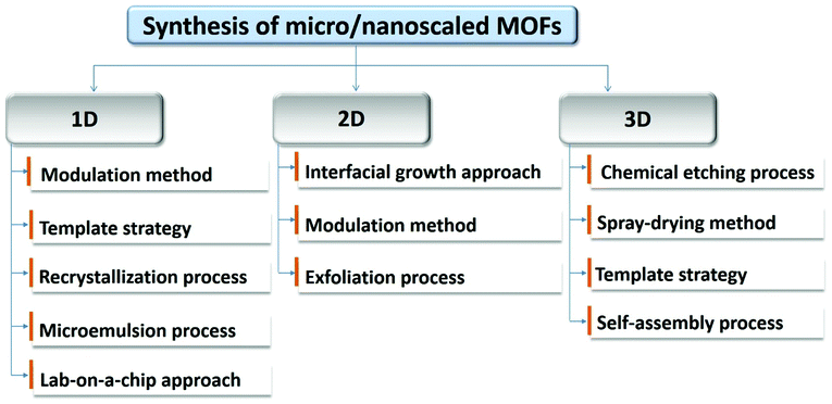
In this review, we will summarize and analyse the recent progress in the synthesis of micro/nanoscale MOFs and the use of them in electrochemistry as electrode materials. We first present the examples and advanced synthetic technologies for 1D, 2D and 3D MOFs (Fig. 1), and subsequently introduce their electrochemical applications for batteries, including lithium-ion (LIBs),72 lithium–sulfur (Li–S),73,74 lithium–air (Li–O2),75,76 sodium-ion (SIBs)77 and potassium-ion batteries (KIBs),78 SCs79 and electrocatalysis, including OER,80 ORR,81 HER45 and CO2RR,82 which we hope will be helpful for understanding the recent developments of MOF chemistry and their applications in various fields.
2. Synthesis of micro/nanoscaled MOFs
Controlling the morphology and size of MOF structure is vital to their applications. In the past decade, some advanced methods have been applied to synthesize and construct MOFs with specific functionalities. Next, we will focus on the synthetic strategies for micro/nanosized MOF structures with specific geometric morphologies, including 1D, 2D and 3D structure.2.1 One-dimensional micro/nanoscaled MOFs
Owing to the unique anisotropic properties of 1D nanostructures, the pace of manufacturing of 1D MOF nanomaterials for specific applications has significantly accelerated. 1D nanometre-sized MOF materials with fascinating properties and tailorable configurations, such as nanowires,83 nanorods,84,85 and nanofibres, can be achieved through the selection of both the organic ligands and the inorganic metal ions.86,87 Until now, the most commonly used methods for fabricating these structures are the self-assembly of organic ligands and inorganic metal ions through a one-pot strategy. However, compared to 0D nanoparticles, it is more challenging to produce micro/nanoscaled 1D MOFs with controllable morphology and architecture. Even though so-called 1D MOF nanostructure can be achieved by an electrospinning method, the final products are composites of MOFs and polymers, which are not real 1D MOF structures and are not included in this review.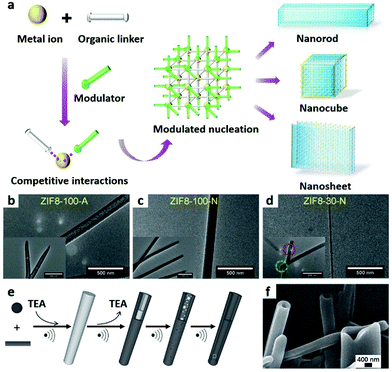 | ||
| Fig. 2 (a) Schematic illustration of synthesis of nanoMOFs by the coordination modulation method. TEM images of (b) nanotubes, (c) nanorods and (d) nanowires of ZIF-8. Reproduced with permission.43 Copyright 2018, Wiley-VCH. (e) Schematic illustration of the self-sacrificing template strategy. (f) SEM image of 1D TEA MOF nanotubes. Reproduced with permission.94 Copyright 2012, Wiley-VCH. | ||
1D MOF nanotubes can also be prepared through a self-sacrificing template route (Fig. 2e) by using MOF nanorods as the template, which were first synthesized by using triethylamine (TEA) as a deprotonating agent. The removal of excess TEA from the MOF nanorods under ultrasonic conditions dissolves the initial MOF nanorods. As a result, a new MOF phase is formed on the surface (Fig. 2f).94
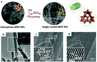 | ||
| Fig. 3 (a) Schematic illustration of synthesis of 1D superlong single-crystal MOF nanotubes by the amorphous MOF-mediated recrystallization approach. (b–d) TEM images of single-crystal nanotubes. Reproduced with permission.42 Copyright 2018, American Chemical Society. | ||
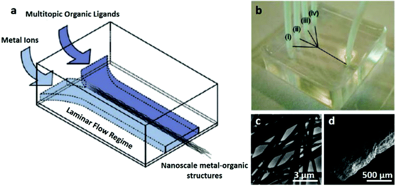 | ||
| Fig. 4 (a and b) Schematic illustration of synthesis of 1D Cu(II)-Asp MOF nanofibers by a lab-on-a-chip approach. (c) TEM and (d) SEM images of 1D Cu(II)-Asp MOF nanofibers. Reproduced with permission.86 Copyright 2011, American Chemical Society. | ||
In addition to the above mentioned approaches, other methods, including hydrothermal/solvothermal synthesis or electrospinning, are also widely used for 1D MOFs and MOF composites. The solvothermal method is a self-assembly process of metal ions with organic frameworks.95 However, the products from electrospinning are hybrids of MOFs and organic materials, which we will not focus on.
2.2 Two-dimensional micro/nanoscaled MOFs
In the past ten years, new methods for the controlled formation of 2D nanostructures, such as thin films,80,96,97 membranes98 and nanosheets,99–102 have been developed. Due to the characteristics of high aspect ratios and abundant active sites, ideally ultrathin, single or multiple 2D MOF nanostructures have great significance for electrochemical applications including catalysis, sensing and so on. Two important strategies, top-down103,104,111 and bottom-up105 approaches, are commonly used to prepare 2D MOF architectures. Among them, the bottom-up method usually focuses on interfacial synthesis106–108 and modulated synthesis,99,109,110 while the top-down approach is achieved by the exfoliation of bulk MOFs, which includes mechanical or chemical exfoliation80,103,111–114 and so on.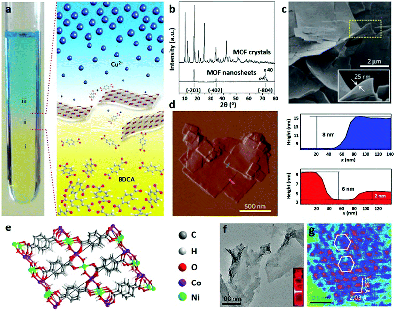 | ||
| Fig. 5 (a) Schematic illustration of synthesis of CuBDC nanosheets by the interfacial growth approach. (b) XRD patterns of bulk and nanosheet CuBDC. (c) SEM and (d) AFM images of CuBDC nanosheets with the corresponding height profiles. Reproduced with permission.115 Copyright 2014, Nature Publishing Group. (e) Schematic illustration of the structure of NiCo-UMOFNs. (f) TEM and (g) HAADF-STEM images of NiCo-UMOFNs. Reproduced with permission.23 Copyright 2016, Nature Publishing Group. | ||
Recently, two novel approaches have been applied for preparing 2D MOF nanofilms. One is the step-by-step approach based on liquid-phase epitaxy, which can be used to control the growth orientation on a substrate.117–120 For example, Otsubo et al.120 prepared a highly oriented MOF thin film (Fe(pz)[Pt(CN)4]) on metal substrates with a thickness of 20–50 nm by this process (Fig. 6a). The other approach comprises the so-called Langmuir–Blodgett (LB) technique and the layer-by-layer (LbL) strategy, in which nanofilms are formed on the liquid surface. Recently, Sakaida et al.97 have reported a crystalline thin film of Fe(py)2[Pt(CN)4] (py, pyridine) via the LbL strategy. The MOF is composed of interdigitated 2D layers, exhibiting dynamic guest-sorption behaviour with a nanometre-sized thin film morphology. Sometimes, the combination of these two methods is more efficient in designing 2D nanoMOFs (Fig. 6b). Even under mild conditions, highly crystalline MOF nanofilms (NAFS-2) on both silicon and gold surfaces can be prepared (Fig. 6c).121 Moreover, the layer-structured MOF nanofilms consisting of copper ions and H2TCPP molecules (Cu–TCPP) can be easily anchored on various substrates with controllable thickness.97,105,109,122–124 In addition, multiple layers of Cu-MOF nanofilms with a thickness of about 10 nm are also achieved by the combination of the LB and LbL methods (Fig. 6d).125
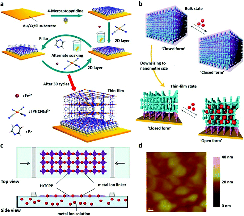 | ||
| Fig. 6 (a) Schematic illustration of the step-by-step approach for fabricating Fe(pz)[Pt(CN)4] MOF thin films. Reproduced with permission.120 Copyright 2012, American Chemical Society. (b) Dynamic structural response to guests induced by crystal downsizing from bulk to nanosized MOF thin films. Reproduced with permission.97 Copyright 2016, Nature Publishing Group. (c) Synthesis of NAFS-2 by a combination of LB and LBL methods. Reproduced with permission.121 Copyright 2011, American Chemical Society. (d) AFM image of NAFS-2 on a gold substrate. Reproduced with permission.125 Copyright 2016, American Chemical Society. | ||
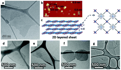 | ||
| Fig. 7 (a) TEM and (b) AFM images and (c) structural illustration of Zn–TCPP nanosheets with Zn2(COO)4 paddlewheel metal nodes and TCPP ligands. Reproduced with permission.109 Copyright 2014, Wiley-VCH. TEM images of (d) Cu–TCPP(Fe), (e) Cd–TCPP(Fe), (f) Co–TCPP(Fe) and (g) Zn–TCPP(Fe) nanosheets. Reproduced with permission.99 Copyright 2015, Wiley-VCH. | ||
Since surfactants may block the active sites when the nanosheets are used as catalysts, the complete removal of surfactants after their synthesis is necessary, which is however not so straightforward in most cases.109 To overcome these challenges, Hu et al.295 synthesized 2D NUS-8 (Zr and Hf) MOF nanosheets directly by a heterogeneous modulated hydrothermal method, which takes the advantages of the mutual osmotic inhibition of heterogeneous solutions that make the rapid precipitation of intermediate products possible. During the synthesis process, the prepared NUS-8 nanosheets exhibit superior stability and catalytic activity over their interlocked 3D MOF analogues synthesized solvothermally.296
As ultrasonic exfoliation is a common method to obtain micro/nanosized materials, it is a good choice to exfoliate bulk laminar MOFs by the ultrasound-assisted strategy. In Gallego's work,126 monolayer MOF nanosheets are easily achieved by the exfoliation of the laminar MOF [Cu(μ-pym2S2)(μ-Cl)]n·nY (Y = EtOH, H2O, MeOH) under ultrasound conditions. This method can also avoid potential complications because solvent-assisted processes involve relatively soft energy. By using ultrasound, functional cobalt terephthalate MOF nanosheets (u-CoOHtp) with oxygen vacancies are synthesized. When used as an electrode material in batteries, the oxygen vacancies in u-CoOHtp can cause local built-in electric fields, thus accelerating the ion diffusion rate and promoting reversible Na storage.127
Apart from the chemical exfoliation process, physical exfoliation is also used for preparing 2D nanostructures. However, due to the low structural stability of MOF nanosheets, their in-plane structure may be destroyed by traditional physical exfoliation. Thus, soft physical exfoliation based on the combination of wet ball milling and ultrasonic peeling is a potential alternative. For example, first, the layered Zn2(Bim)4 crystal was wet-ball-milled at a very low speed and then exfoliated in a solvent mixture of methanol and propanol, resulting in the formation of 1 nm-thick molecular sieve MOF nanosheets (Fig. 8a–c). In this process, wet-ball-milling contributes to the penetration of small molecules into the cavities of layered MOFs, while propanol contributes to stabilizing the structure of exfoliated nanosheets.112 Taking advantage of this functional process, the exfoliation process is easily achieved and the obtained colloid of MOF nanosheets is stable at room temperature for several months.
 | ||
| Fig. 8 (a) SEM image of as-synthesized Zn2(bim)4 crystals. (b) TEM and (c) AFM images of Zn2(Bim)4 nanosheets (the inset image in (b) shows the Tyndall effect of a colloidal suspension). Reproduced with permission.112 Copyright 2014, Science. | ||
2.3 Three-dimensional micro/nanoscaled MOFs
3D MOFs mainly involve hollow or porous MOF structures with specific morphologies in a 3D space, which are often assembled from simple MOF building blocks, such as MOF nanoparticles, MOF nanorods and MOF nanosheets.89,108,128–132,300,301 These 3D assemblies constructed from simple components can inherit the exceptional properties of their building blocks such as 0D nanoparticles, 1D nanorods/wires and 2D nanostructures, and acquire certain unconventional advantages.133 Owing to their unique 3D structure, the 3D MOFs are beneficial for applications in energy storage,134–137 chemical sensing,138 and chemical catalysis.24 However, the design and fabrication of a well-defined 3D MOF at the nano/micro-scale is still difficult, especially for architectures composed of simple building units with ordered morphologies. In recent years, synthesis strategies for the templating, etching and self-assembly of 3D micro/nanoMOFs have attracted great attention, benefiting from the precise control of the morphology or pore structures of the products.46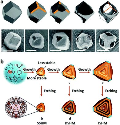 | ||
| Fig. 9 (a) Schematic illustration and SEM images of ZIF-67 during the etching process (pH = 2.5). Scale bars: 1 μm. Reproduced with permission.142 Copyright 2015, Wiley-VCH. (b) Schematic illustration of synthesis of single, double and triple-shelled hollow MIL-101 by acetic acid etching processes. Reproduced with permission.129 Copyright 2017, Wiley-VCH. | ||
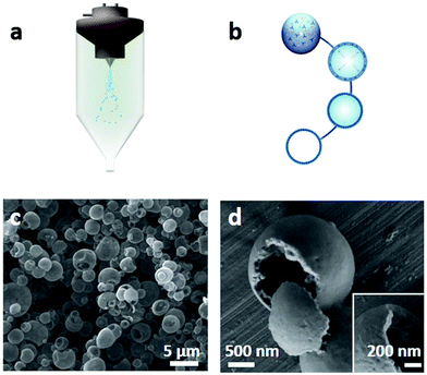 | ||
| Fig. 10 (a and b) Schematic illustration of synthesis of spherical hollow HKUST-1 superstructures by spray-drying methods. (c and d) SEM images showing the hollow structure of HKUST-1. Reproduced with permission.132 Copyright 2013, Nature Publishing Group. | ||
This vesicle-template strategy also provides a feasible approach for constructing hierarchical MOFs with defect sites and mesopores.147
Benefitting from templates that can regulate the morphologies and pore sizes of the resulting products, a single-crystalline MOF with 3D ordered macro-micropores is synthesized by using 3D polystyrene spheres as templates with a subsequent etching process.148 In this strategy, monodisperse polystyrene spheres (PSs) are first assembled into highly ordered 3D PS monoliths (Fig. 11). Then, ZIF-8 precursors are filled into the interstices of the PS, forming a composite of the “precursor@PS” monolith, which is subsequently soaked in a mixture of methanol and ammonia. Because ammonia can induce the rapid crystallization of the ZIF-8 precursor and methanol adjusts the growth process of ZIF-8 crystals, the precursors smoothly transform into well-defined 3D solid crystals. When removing the PS by immersing these MOF crystals in tetrahydrofuran several times, 3D ordered MOF macro-micropores are obtained, which exhibit highly active catalytic performance for benzaldehyde conversion. In addition, the size of macropores in these single-crystal MOF structures can be facilely controlled by changing the kinds of PSs.
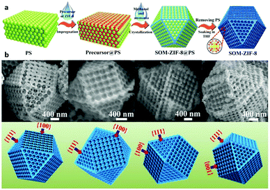 | ||
| Fig. 11 (a) Schematic illustration of synthesis of 3D SOM-ZIF-8 by the template strategy. (b) SEM images of individual SOM-ZIF-8 crystals taken from four different directions. Reproduced with permission.148 Copyright 2018, Science. | ||
By using the self-template strategy, a single-crystal capsular MOF was synthesized.149 The reaction of the ligand 2,4,6-tris(4-pyridyl)pyridine (tpy) with FeNi-MIL-88B results in the formation of a novel MOF shell on the outer shell of the parent FeNi-MIL-88B via a core-to-surface transfer process, in which the openings on the wall can be controlled. These open-capsular MOFs can absorb large amounts of sulfur and iodine, showing high potential for sulfur- and iodine-based energy storage, and can also be used as a precursor/template to prepare carbon nanostructures with various functionalities for electrochemical energy storage and conversion.
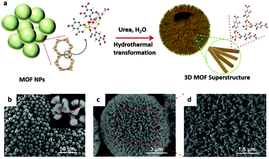 | ||
| Fig. 12 (a) Schematic illustration of synthesis of the 3D spherical superstructure of MOF nanorods by a hydrothermal transformation approach. (b–d) SEM images of the 3D spherical superstructures. Reproduced with permission.46 Copyright 2017, Wiley-VCH. | ||
3. Direct electrochemical application of micro/nanoscaled MOFs
In recent decades, MOF and MOF composites have been widely used in electrochemistry including batteries, SCs and electrocatalysis, owing to their unique characteristics of well-developed porous networks, large surface areas, and facile mass transfer pathways and atomically dispersed metal active sites. However, the wide application of MOFs as electrode materials is still limited by their relatively low conductivity and instability in electrolytes, which can be partially compensated by structural optimization. Thus, decreasing the size of MOFs into the micro/nanoscale and directly using them as electrodes have received great interest in electrochemistry.3.1 Batteries
Reducing bulk MOFs to the nanometre scale to expand their application in energy storage, catalysis, sensing and other fields is a challenge. For example, nanowires are favourable because of their fast transport dynamics, universal structural compatibility and good flexibility. Recent studies have shown that 1D nanomaterials have superior electrochemical activity and capacitance compared to that of their bulk materials. 2D micro/nanoscaled MOFs are suitably recyclable and strong under both chemical and physical attack. In addition, 2D MOFs exhibit promising performance for batteries and excellent electrocatalytic activity towards intercalation/deintercalation of Li+, CO2 reduction and water oxidation. In contrast to traditional electrode systems, the 3D macrostructure or mesoporous structure of the interconnected MOF crystal can facilitate the diffusion of guest molecules into the micropores (and active centres). These functional MOF materials are excellent candidates for batteries and chemical catalysis.99,124–126,139–147Graphite is used as a negative electrode material in traditional LIBs, with a low capacity of 372 mA h g−1 and poor rate performance. As a newly emerged crystalline material, MOFs are attractive electrode materials for LIBs because of their crystalline porous structures and ordered arrangement of metal active sites. So far, micro/nanostructured MOFs have been widely studied as anode and cathode materials for Li rechargeable batteries.151,152 On the contrary, novel MOFs usually ensure structural instability as well as relatively low electrical conductivity.153–156 This problem is optimized by mixing MOFs with conductive carbons in battery tests. Benefitting from their high surface area and porosity, as well as the adjustable metal composition, MOFs can reach an extraordinarily high capacity and relatively large voltage. The crystalline porous structure can also act as a buffer to reduce the bulk change during the lithiation/delithiation process and improve the safety of batteries, which is incomparable to that of commercial carbon or other metal oxide materials. At the early stages, Férey and Serre et al.162,163 developed MIL-53(Fe) as a cathode material for LIBs. Then, to comprehensively understand the extraction/insertion mechanism of Li+ in MOFs, first-principles DFT+U (i.e., density functional theory) calculations were used for MIL-53 and Fe(III)(OH(BDC)) by Combelles et al.164 To increase the electrochemical capacity of MIL-53 (Fe), another Fe-based MOF (MIL-68 (Fe)) has been investigated by Fateeva et al.165 These works have laid a solid foundation for the study of micro/nanostructure MOF materials in direct electrochemical applications.166,167,169–173
In recent years, the application of 1D MOF nanostructures in batteries has become a hot topic.163–168 The rod-like Mn-BTC (BTC = 1,3,5-benzenetricarboxylate) synthesized via a simple solvothermal method exhibits a good performance for LIBs (Fig. 13a and b).134 When tested in a potential window of 0.01–2.0 V, the anode exhibits a high specific capacity of 694 and 400 mA h g−1 at a current density of 0.1 and 1.0 A g−1, respectively. It also shows good cycling ability, structural stability, and capacity retention (Fig. 13c). In this system, the organic groups are involved in the insertion and extraction of Li+ in the Mn-BTC MOF (Fig. 13d). It is demonstrated that the lithium-containing conjugated carboxylates are weakly electrophilic ligands that can be used as the redox centre for the coordination of Li with COO−.174,175 Compared to bulk MOF structures, 1D MOF nanowires have fast transport dynamics, good flexibility and structural versatility, making them ideal electrode materials in batteries. Song et al.83 synthesized new MOF nanowires, called CoCOP (coordination polymer) nanowires, by a scalable and simple method (Fig. 13e and f). The CoCOP nanowires show an impressive Li+ storage capacity with a value larger than 1100 mA g−1 as an anode material for LIBs (Fig. 13g). In addition to their high energy and power performance, the materials also exhibit good long-term cyclic stability and can be used in more than 1000 completely reversible lithiation desulfurization cycles. This process is based on a joint mechanism involving intercalated structure deformation and Co(II)/Co conversion reactions. Due to the reversible structural deformation and the conversion reaction between Co(II) and Co(0), the cell performance is improved reasonably (Fig. 13h). The successful application of MOF nanowires in CoCOP–LiFePO4 cells also indicates the feasibility of using CoCOP nanostructures in large-scale energy storage applications.
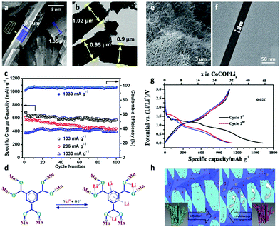 | ||
| Fig. 13 (a) SEM and (b) TEM images of Mn-BTC microrods. (c) Cyclic performance of Mn-BTC microrods at different current rates. (d) Proposed lithiation/delithiation sites in the organic moiety of Mn-BTC microrods. Reproduced with permission.134 Copyright 2015, American Chemical Society. (e) SEM and (f) TEM images of CoCOP nanowires. (g) Initial discharge/charge curves of CoCOP nanowires. (h) Schematic illustration of the interpenetrating tunnel for Li+ transport in lithiation/delithiation processes. Reproduced with permission.83 Copyright 2016, The Royal Society of Chemistry. | ||
The charge storage mechanism of lithium ion batteries includes electron transfer between the electrolyte and electrode and electron transfer in the electrode itself. Therefore, good electrical conductivity is crucial for electrodes, while the complex secondary building unit (SBU) and pore structure of MOFs may make the transfer path of Li+ more difficult in the process of lithiation and delithiation, leading to poor cycling performance and rate performance. Thus, the conductivity of 2D MOFs with layered structures might be improved by the facile transfer of the electrolyte between the interlayers. For example, Gu et al.72 prepared conductive MOF Cu3(2,3,6,7,10,11-hexahydroxytriphenylene)2(Cu3(HHTP)2) nanosheets as the cathode active material in LIBs (Fig. 14a and b). The Cu3(HHTP)2 electrode exhibits a specific capacity of 95.61 mA h g−1, which is nearly equal to its theoretical value (Fig. 14c).
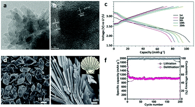 | ||
| Fig. 14 (a and b) TEM images of Cu3(HHTP)2) nanosheets. (c) Galvanostatic charge/discharge curves of Cu3(HHTP)2 nanosheets as a cathode between 1.7 and 3.5 V at a 1C rate for LIBs. Reproduced with permission.72 Copyright 2019, Elsevier Ltd. (d and e) SEM images of S-Co-MOF accumulation nanosheets. (f) Capacity retention and coulombic efficiency of S-Co-MOF accumulation nanosheets at a current rate of 100 mA g−1. Reproduced with permission.135 Copyright 2016, The Royal Society of Chemistry. | ||
In 2016, Peng et al.102 discussed the electrochemical performance of 2D Cu-TCA (H3TCA = tricarboxytriphenyl amine) as a positive material in LIBs. The Cu-MOF possesses redox activity with both the organic ligand radicals (N/N+) and metal clusters (Cu+/Cu2+), exhibiting separated voltage plateaus and a high working potential vs. Li/Li+ of up to 4.3 V. Long cycling stability was achieved for this Cu-MOF, showing a coulombic efficiency of 96.5% for 200 cycles at a 2C rate. Liu et al.176 have reported a Mn-based layered coordination polymer ([Mn-(tfbdc)(4,4′-bpy)(H2O)2] as an anode material, which provides a feasible strategy for synthesizing new electrode materials for LIBs. In 2016,135 a seashell-like Co-based MOF formed by the accumulation of nanosheets, referred to as S-Co-MOF (Co2(OH)2BDC), was synthesized and used as an electrode for LIBs (Fig. 14d and e). After going through 200 cycles of charge and discharge, the synthesized S-Co-MOF still maintained a high reversible capacity of 1021 mA h g−1 at 100 mA g−1, and the initial coulombic efficiency also reached 80.4%. This is because the Li+ intercalation/deintercalation mechanism is dominated by the organic moiety (Fig. 14f). The unique 3D interconnected channels are another merit of MOFs for use in LIBs, enabling rapid diffusion of Li+.177
Because MOFs are crystalline porous materials with variable compositions, they are good representatives for exploring the correlation between the structural design and properties.157–162 The microstructured MIL-177 (Zn4O, (1,3,5-benzenetribenzoate)2) exhibits a high irreversible capacity for the first discharge as an anode material in LIBs.178 However, these results are still far from satisfactory. Since increasingly more 3D MOF structures have been investigated as cathode or anode materials, great progress has been achieved in this regard.
More recently, the electrochemical properties of Co 1,3,5-benzenetricarboxylate (named as CoBTC) with various morphologies and sizes have been studied by Li et al.136 The product of CoBTC–EtOH, monodisperse hollow microspheres with a particle size of 3–8 μm (Fig. 15a and b), has a high reversible capacity and good cyclic stability at high rates (≥2 A g−1), as illustrated in Fig. 15c.179,180 The Ti-based MOF (Ti-MOF), with a steady Ti-skeleton and hexagonal nut shape, provides channels for deintercalation of Li+ due to its special porous structure, improving the contribution of the pseudocapacitive process, and showing an excellent capacity of the initial discharge capacity of 1590.24 mA h g−1 at 100 mA g−1. It should be noted that the O atoms of the carboxyl group have a strong interaction with the Ti(IV) ions, and thus the Ti(IV)-carboxylate MOF has excellent chemical stability, which is conducive to the charge and discharge cycle. In addition, the synergy between the porous structure and the active organic ligands, as well as the excellent stability of the flexible layer structure, could contribute to its excellent electrochemical properties.
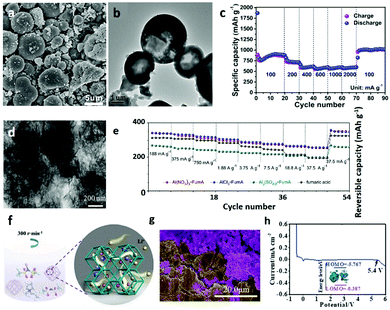 | ||
| Fig. 15 (a) SEM and (b) TEM images of CoBTC microparticles. (c) Rate performances of CoBTC microparticles at different current densities from 100 to 2000 mA g−1. Reproduced with permission.136 Copyright 2016, American Chemical Society. (d) TEM image of the tremella-like AlCl3-FumA MOF. (e) Rate capability of the Al(NO3)3-FumA, AlCl3-FumA, Al2(SO4)3-FumA and FA electrodes. Reproduced with permission.181 Copyright 2017, Elsevier Ltd. (f) Schematic illustration of ILE@MOF synthesis and Li+ transport paths. (g) SEM image of the Li metal and ILE@MOF (green represents the Li metal and purple represents the electrolyte). (h) LSV curves of a Li/ILE@MOF/stainless steel (SS) cell at a scan speed of 0.1 mV s−1. Reproduced with permission.188 Copyright 2019, The Royal Society of Chemistry. | ||
Similar to other 3D structures assembled by simple 1D or 2D structures, 3D MOF materials fabricated by the stacking of ultrathin MOF nanosheets show good rate performances and long stability when used as cathode materials in LIBs.181 Electrochemical and spectroscopic studies have shown that the low impedance reversible lithium/delithiation process is closely related to the ultrathin and stable structure of the material during electrochemical cycling (Fig. 15d and e).
Recently, a novel bifunctionalized MOF (Zn(IM)1.5(abIM)0.5, IM = imidazole, referred to as BMOF) has been developed as an anode material for LIBs, which exhibits remarkable hydrophobic and polar properties.182 During the discharging and charging processes, the microscaled framework can remain intact, and Li+ are indeed stored in the pores of this BMOF. As the storage behaviour involves a guest/host interaction between the Li and amine/N atoms, the capacity can be further improved by increasing the number of active N-rich functional groups. With the development of technologies in MOF syntheses and applications, other micro/nanosized MOFs, including Co2(OH)2BDC, Ni-Me4bpz (C20H24Cl2N8Ni) and Asp(aspartic acid)–Cu, have also been constructed and studied as anode materials for LIBs.84,183–187 These MOF anode materials show quite high reversible capacities and rate performances for LIBs. The above studies indicate that both the organic ligands and metallic centre alloy-type process play important roles in the conversion process.
Traditional electrolytes in Li-metal batteries are flammable and volatile, which increases the consumption of lithium at high temperatures, leading to catastrophic fires or explosions. Therefore, a Li+ conductive MOF electrolyte (ILE@MOF) (obtained by mixing ZIF-67 particles with an ionic liquid electrolyte (ILE) by simple ball milling) was designed to perform dendrite-free Li deposition at high temperatures (Fig. 15f and g).188 This electrolyte stabilizes the electrolyte/electrode interface by enhancing the transport of lithium ions and reduces the formation of lithium dendrites by forming a pellet-rich coating on the anode during repeated lithium plating/stripping (Fig. 15h). Due to the strong interaction between metal atoms and TFSI-anions, the coordination environment of Li+ is weakened and the mobility is enhanced. Therefore, when the MOF 3D channel is encapsulated, the ILE will not lose its dynamic mobility and maintain a high ionic conductivity.
In fact, the uncontrolled growth of lithium dendrites during deposition and stripping leads to low coulombic efficiency and serious safety risks of Li metal batteries. A metal–organic skeleton (MOF-199), as a strong shield, homogenizes lithium ion concentration through its highly polar structure, and its porosity and strong shield can physically inhibit the growth of lithium dendrites and relieve excess SEI formation.189 The MOF-199-coated Cu electrode shows great application prospects owing to the extra resistance supplied by the MOF-199 layer. Compared to the pristine Cu electrodes with a rapid decrease in performance after 180 cycles, with CEs of only 21% and 8% after 300 cycles at 2 and 3 mA cm−2, respectively, the MOF-199-coated Cu electrode maintains a higher current density with a retention of 96% for 350 cycles.
Zheng et al.198 proposed the Lewis acid–base interaction model of Ni-MOF-S composite material for the interaction between the Ni-MOF matrix and sulfur. The capacity retention can reach 89% after 100 cycles at 0.1C. The excellent properties of the Ni-MOF are attributed to the synergistic effects of the interwoven mesopores (2.8 nm) and micropores (∼1.4 nm), providing a perfect environment for limiting polysulfides. Since the morphology of MOFs is a vital factor affecting the utilization of sulfur or polysulfides during the charge and discharge process, studies were conducted on the particle sizes and aperture windows of a series of MOF materials, such as MIL-53 (Al), NH2-MIL-53 (Al), HKUST-1 and ZIF-8 (Fig. 16a and b)).199 ZIF-8 with a particle size between 100 and 200 nm and an aperture window of 3.4 Å showed the best Li–S battery performance among the studied samples (as shown in Fig. 16c). It is proposed that the MOF particle size affects the sulfur utilization rate and initial discharge capacity of the battery, while the aperture size of MOFs affects the conversion rate of polysulfide, which means that a well-designed orifice should promote the diffusion of lithium ions and retain polysulfide in the host (Fig. 16d and e). Generally, the low conductivity of the MOFs and sulfur leads to a low utilization of the MOF-S composites compared to the C/S composites, while nanostructures can significantly improve their performance in Li–S batteries. Qian et al.200 reported a Co-based MOF (HKUST-1) that uses sulfur as the cathode material for Li–S batteries. XPS tests have shown that reversible interactions between sulfur and open metal sites during discharge and charging reduce the release of dissolved polysulfide in the electrolyte.
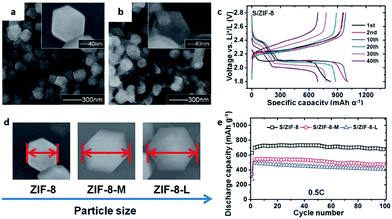 | ||
| Fig. 16 SEM images of (a) ZIF-8 nanocrystals and (b) S/ZIF-8. (c) Rate capabilities of S/ZIF-8. (d) SEM images and (e) discharge capacities of ZIF-8 (at 0.5C) with different particle sizes. Reproduced with permission.199 Copyright 2014, The Royal Society of Chemistry. | ||
The activated MOF not only features physical adsorption and chemical adsorption, but can also facilitate highly efficient sulfur impregnation and large-scale transportation. In this regard, the 9-manganese node-based MOF is prepared by cubic cages filled with coordinated water (Mn-CCs–xH2O), which was designed as an effective cathode host material, and the constructed battery showed a prominent initial specific capacity of 1460 mA h g−1 at 0.2C and cycle stability, with the remaining specific capacity of 990 mA h g−1 after 200 cycles.201
With high surface area, accessible metal position and flexible structure, the MOF is a good catalyst for improving the cycling performance of lithium oxygen batteries.168,204–206,213–215 MOF-74, possessing a highly porous (hexagonal) structure with a 1D channel, has many open sites on the channel surface to absorb O2. M-MOF-74 (M = transition metals) was previously applied to Li–O2 batteries as an air cathode. By using a modulator in a mixed solvent system, Yan et al.76 reduced the size of Co-MOF-74 to several unit lengths, with an average diameter of 20 nm and a length/diameter ratio of 12. Compared with the pure carbon electrode, the Co-MOF-74 nanofibre electrode has higher discharge capacity and better rate performance. In addition, MOF-74 synthesized by different kinds of metals, such as Mn, Co, Ni, or their bimetallic combination, has been studied. The mixed bimetallic MnCo-MOF-74 with a nanorod-like morphology was used as a cathode catalyst in Li–O2 batteries (Fig. 17a), showing a high full discharge capacity (11![[thin space (1/6-em)]](https://www.rsc.org/images/entities/char_2009.gif) 150 mA h g−1) and excellent cyclability (44 cycles) with low overpotential at a limited capacity of 1000 mA h g−1 (Fig. 17b–d). As shown in Fig. 17e, the MnCo-MOF-74 sustains the lowest charge end voltage and the most excellent discharge end voltage.
150 mA h g−1) and excellent cyclability (44 cycles) with low overpotential at a limited capacity of 1000 mA h g−1 (Fig. 17b–d). As shown in Fig. 17e, the MnCo-MOF-74 sustains the lowest charge end voltage and the most excellent discharge end voltage.
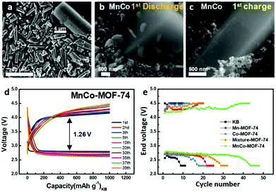 | ||
| Fig. 17 SEM images of MnCo-MOF-74 microrods (a) before and (b and c) after the discharging and recharging process. (d) MnCo-MOF-74 at a limited capacity of 1000 mA h g−1 with a current density of 200 mA g−1. (e) End voltage VS. cycle number of the carbon black, Mn-MOF-74, Co-MOF-74, mixture-MOF-74 (physical mixing) and MnCo-MOF-74 microrods. Reproduced with permission.75 Copyright 2017, American Chemical Society. | ||
The structural characteristics of MOFs with an ideal size and morphology enable us to systematically design pores with high density unsaturated electrochemical active sites for electrochemistry, as well as efficient diffusion paths with a low electron and mass transport barrier. Therefore, three kinds of 2D MOFs are synthesized through a facile ultrasonic method with highly efficient cathode catalysts for aprotic Li–O2 batteries113 Because the 2D Mn-MOF possesses a large specific surface area, open catalytic sites and Mn–O clusters with high electrocatalytic activity, which make contributions to mass transfer (O2 and Li+) and the effective contact (electrolyte/electrocatalytic active sites), the rechargeable Li–O2 batteries show long cycling life and a superior rechargeability.
It was demonstrated that the oxygen vacancies in cobalt terephthalate-based MOF nanosheets (ultrathin-CoOHtp) could induce local built-in electric fields, which is capable of improving the ion diffusion rate and thus promote the reversible Na+ storage (Fig. 18a and b). As an active anode of Na+ coin cells, the ultrathin 2D nanosheet can provide both a great number of electroactive sites to guarantee a high Na-storage capacity and short ion/electron diffusion paths to the internal active sites. The in-plane local electric fields that are created by generated self-adaptive oxygen vacancies could accelerate Na+/e− migration rates and facilitate the charge transfer behaviour (Fig. 18c).127
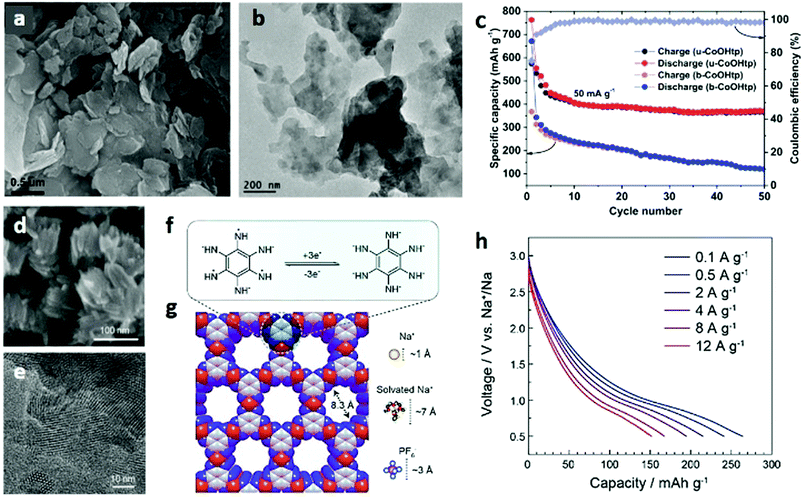 | ||
| Fig. 18 (a) SEM and (b) TEM images of ultrathin CoOHtp nanosheets. (c) Cycling performances of the ultrathin CoOHtp nanosheets at a current density of 50 mA g−1. Reproduced with permission.127 Copyright 2018, Elsevier Ltd. (d) SEM and (e) TEM images of Co-HAB nanoparticles. (f) Proposed three-electron reversible reaction and (g) calculated structure of Co-HAB nanoparticles. (h) Rate performances of Co-HAB as an electrode material for SIBs. Reproduced with permission.224 Copyright 2018, American Chemical Society. | ||
Recently, inexpensive materials of PB and its analogues (KMFe(CN)6, M = Fe, Mn, Ni, Cu, Co and Zn) have been demonstrated as new cathode materials for SIBs with saturated NaClO4 in 1![[thin space (1/6-em)]](https://www.rsc.org/images/entities/char_2009.gif) :
:![[thin space (1/6-em)]](https://www.rsc.org/images/entities/char_2009.gif) 1 EC/DEC (vol:vol) electrolytes. Lu et al.225 reported an iron-oxalato open 3D framework (K4Na2[Fe(C2O4)2]3·2H2O) synthesized by a simple hydrothermal process for SIBs. The KFe2(CN)6–Na battery in EC
1 EC/DEC (vol:vol) electrolytes. Lu et al.225 reported an iron-oxalato open 3D framework (K4Na2[Fe(C2O4)2]3·2H2O) synthesized by a simple hydrothermal process for SIBs. The KFe2(CN)6–Na battery in EC![[thin space (1/6-em)]](https://www.rsc.org/images/entities/char_2009.gif) :
:![[thin space (1/6-em)]](https://www.rsc.org/images/entities/char_2009.gif) DEC (1
DEC (1![[thin space (1/6-em)]](https://www.rsc.org/images/entities/char_2009.gif) :
:![[thin space (1/6-em)]](https://www.rsc.org/images/entities/char_2009.gif) 1 v/v) with 1 M NaClO4 as the electrolyte was cycled at C/20 rate 30 times at room temperature. The results indicate that the PB framework shows excellent capacity retention, with a value of more than 99% after 30 cycles.
1 v/v) with 1 M NaClO4 as the electrolyte was cycled at C/20 rate 30 times at room temperature. The results indicate that the PB framework shows excellent capacity retention, with a value of more than 99% after 30 cycles.
To improve the conductivity of the electrode, a new cobalt-based conductive MOF (Co-HAB, composed of Co(II) ion node and redox active hexaaminobenzene (HAB)) with a particle size of ∼75 nm has been developed for SIBs (Fig. 18d and e).224 In this study, through the tunability of the synthesis process of Co-HAB, a volume electronic conductivity of 1.57 S cm−1 was obtained. The reversible three-electron redox reaction was successfully carried out for the first time (Fig. 18f and g). A capacitance of 152 mA h g−1 can be obtained in 45 s, demonstrating their extremely high rate capability (Fig. 18h). When the active mass loading increases to 9.6 mg cm−2, the area capacity is almost linear. The above results suggest that Co-HAB is an excellent choice for manufacturing high power electrode materials for fast sodium ion batteries or hybrid capacitors.
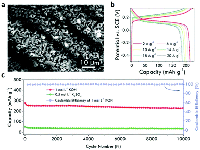 | ||
| Fig. 19 (a) SEM image of stacked NiCo-MOF nanosheets growing on nickel-plated carbon cloth. (b) Charge and discharge profiles of the NiCo-MOF cathode at various current densities. (c) Cycle stability of a NiCo-MOF/PAQS (anthraquinonyl sulfide) full cell at 2 A g−1. Reproduced with permission.78 Copyright 2019, Elsevier Ltd. | ||
3.2 Supercapacitors
SCs, also called electric double layer supercapacitors (EDLCs), usually use carbon materials with porosity and high specific surface area. However, physical charge storage and energy density of EDLCs are both very low.79,237–242 Thus, pseudocapacitors with transition metal sulfides and oxides have attracted increasing attention. In recent years, micro/nanoscaled MOFs have shown great potential and advantages in this application due to their high specific surface area, controllable pores and diverse metal species.241,243,244As a promising electrode material, the 1D Ni-MOF nanostructure has attracted great interest in SCs.245 To improve the capacitance, strategies based on multiple metal compositions are usually applied. For example, bi-metallic NiCo-based MOF micro-nanorods exhibit high capacitance retention and excellent rate capability, showing a high specific capacitance of 990.7 F g−1 at 1 A g−1.246 Another efficient strategy to enhance the performance of SCs is to combine the MOFs with conductive supports (Fig. 20a). By using carbon fibre paper as a support, conductive Cu-HHTP nanowire arrays have been synthesized, which are used as electrode material for solid-state SCs and show excellent capacitance properties owing to their advantages of the full use of high porosity and nanostructure as well as good conductivity (Fig. 20b–d). Compared with those of Cu-HHTP powder, the properties of the Cu-HHTP nanowire array structure were obviously improved (Fig. 20e).247
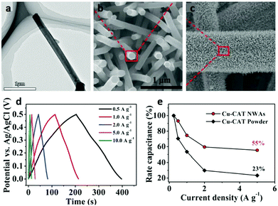 | ||
| Fig. 20 (a) TEM image of a Cu-HHTP nanowire. (b and c) SEM images of Cu-HHTP nanowire arrays growing on carbon fiber paper. (d) Galvanostatic charge and discharge curves at different current densities for Cu-HHTP nanowire arrays as electrodes. (e) Comparison of rate performance of Cu-HHTP nanowire arrays and Cu-HHTP powder. Reproduced with permission.247 Copyright 2017, Wiley-VCH. | ||
Based on the “one-for-all” strategy, positive and negative electrodes are designed from Ni-based MOF nanorods grown on carbon fibre paper, and the constructed hybrid electronic device exhibits a wide voltage window of 1.5 V with a high sloping discharge plateau between 1 and 1.2 V.248 In addition, the 1D MOF nanostructure with rod array morphology, which can be achieved from nickel foam serving as both the nickel ion source and current collector, has been used as an electrode material in SCs.249
Compared with 1D MOF structures, 2D layered MOFs can further offer interspaces between the layers, which might facilitate the diffusion of electrolyte ions and enhance their properties. Thus, 2D MOFs can act as excellent electrode candidates for SCs. Very recently, by deposition of MOF nanocrystals on a substrate to form thin MOF films, the capacitance of a variety of MOF systems has been studied, and these nanoMOF structures exhibit similar general behaviours in their CV curves and cycling performances as those observed in other SCs.250 In Yang's work, a 2D layered Co2(OH)2C8H4O4 MOF was synthesized and used as an electrode material for SCs251 (Fig. 21a and b). Taking advantage of the unique 2D nanostructure, the Co2(OH)2C8H4O4 MOF exhibits a high specific capacitance of 1127 F g−1 at a current density of 0.5 A g−1 in KOH solution (Fig. 21c).16 Similar to the Ni-based MOFs, the Co-based layered MOF (Co-LMOF) also shows a high specific capacitance and good cycling stability when it is used as an SC electrode.252 In 2016, our group253 reported a facile hydrothermal approach to fabricate an accordion-like assembly of Ni-based MOF nanosheets ([Ni3(OH)2(C8H4O4)2(H2O)4]·H2O) (Fig. 21d and e). Electronic measurements indicated that the as-prepared MOF exhibited an exceptional specific capacitance of 988 F g−1 at 1.4 A g−1 with good flexibility (Fig. 21f). Moreover, a remarkable specific capacitance of 230 F g−1 at 1.0 mA cm−2 was achieved in the assembled symmetric flexible solid-state SC. In addition to the above mentioned 2D MOFs, 2D Co-MOF nanosheets consisting of coordinated Co2+ and BDC were tested in a traditional three-electrode system. The maximum specific capacitance of these ultrathin 2D Co-MOF nanosheets reached as high as 1159 F g−1, which is much better than that of both bulk Co MOF and micro/nano Co-MOF under the same testing conditions. Moreover, aqueous electrochemical energy storage devices were assembled by using these ultrathin 2D Co-MOF nanosheets as active materials, giving the maximum specific capacitance of 182.5 F g−1 under aqueous conditions.106
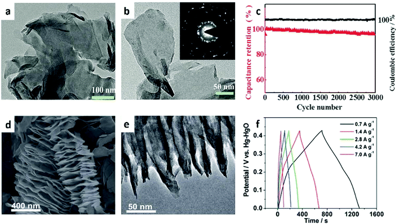 | ||
| Fig. 21 (a and b) TEM images of Co2(OH)2C8H4O4 nanosheets. The inset in (b) shows the SAED pattern of Co2(OH)2C8H4O4 nanosheets. (c) Charge/discharge profile (black line) and specific capacitance (red line) of the Co2(OH)2C8H4O4 nanosheet electrode at a current density of 2 A g−1. Reproduced with permission.101 Copyright 2016, Wiley-VCH. (d) SEM and (e) TEM images of the accordion-like Ni-MOF. (f) Galvanostatic charge/discharge curves at different current densities. Reproduced with permission.253 Copyright 2016, The Royal Society of Chemistry. | ||
Recently, some studies have concentrated on the design and synthesis of 3D MOFs for SCs owing to their unique 3D geometric structure. Although the relatively poor electrical conductivity of MOFs hinders the direct use of MOFs as electrode materials, recent reports show that some MOFs exhibit a comparable or even higher performance than carbon based materials. Sheberla et al.17 showed that Ni3(HITP)2 (HITP = 2,3,6,7,10,11-hexaiminotriphenylene), a MOF with one-dimensional cylindrical channels of ∼1.5 nm in diameter and excellent electrical conductivity exceeding 5000 S m−1, can directly act as a sole electrode material in an EDLC without requiring any conductive additives or binders (Fig. 22a–e).
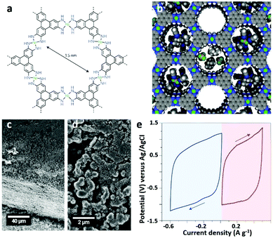 | ||
| Fig. 22 (a) Molecular structure of Ni3(HITP)2. (b) Ideal Ni3(HITP)2 space filling diagram. (c and d) SEM images of Ni3(HITP)2 (packed particles with size ranging from 0.5 to 2 μm). (e) Three-electrode performances of Ni3(HITP)2 at a scan rate of 10 mV s−1 for SCs in the 1 M TEABF4/ACN electrolyte. Reproduced with permission.17 Copyright 2016, Nature Publishing Group. | ||
In the early stages, a Co8-MOF-5 microcrystal (Co-Zn-MOF, with Zn2+ partially replaced by Co2+) was reported as an electrode material for EDLCs.254 Subsequently, Lee et al.255 explored another doctor-bladed Co-based MOF for SCs that showed good pseudocapacitive behaviour (specific capacitance up to 206.76 F g−1) in LiOH solution. Meanwhile, Miles et al.237 evaluated the SC performance of Co-MOF-71 (Co(bdc)(DMF)) microcrystals. Despite its electrical insulation and redox inertness, the as-prepared MOF is a suitable electrode material for SCs with a specific capacitance of 206.76 F g−1 at 0.6 A g−1 in a LiOH electrolyte. This is because the transformation of Co-MOF-71 microcrystals into porous cobalt hydroxide by a “conformal” formation in the alkaline medium leads to easy surface hydrolysis. In addition, even in other electrolytes, such as LiCl, KOH and KCl, the capacitance of the MOFs can retain 98.5% of the original capacity after 1000 cycles under CV measurements. The conformal transformation of Co-MOF-71 into porous electrochemically active cobalt hydroxide was revealed by Lee et al.,256 and the observed colour change and redox peaks in CV experiments were observed. This result is in contrast to opinions that the Co-MOF-71 microcrystals are unchanged in the LiOH electrolyte. Very recently, a microscaled hexagonal Ni-MOF has been fabricated through a one-step solvothermal method by our group.257 In this MOF structure, the largest hexagonal surface is the {001} crystal plane, which is an ideal structure for ion diffusion and electron transport owing to it having the shortest diffusion length for ions compared to that of the rectangular crystal surface. In addition, the cross-linked porous network structure growing on the {001} crystal surface enhances the binding ability with conductive carbons, inducing an improved electrical conductivity. As a result, the hexagonal Ni-MOF shows excellent electrochemical performance as an electrode material for SCs. In a three-electrode battery, the specific capacitance of the MOF structure in the 3.0 M KOH electrolyte is 977.04 F g−1, which can remain at 92.34% of the initial value after 5000 cycles.
3.3 Electrocatalysis
In recent decades, extensive efforts have been applied to synthesize highly active catalysts for electrochemical applications, including the hydrogen evolution reaction (HER), OER, oxygen reduction reaction (ORR) and CO2 reduction reaction (CO2RR), all of which are important technologies in energy storage and conversion. It should be noted that some precious/noble metals and their oxides serve as classical electrode materials/catalysts, but these materials have many problems, such as high cost, scarcity, and low durability. Therefore, researchers have devoted major efforts to fabricating alternative, efficient homogeneous and heterogeneous electrocatalysts.258,262,263 Generally, homogeneous molecular catalysts have advantages of tenability, high activity, convenient structural design, and conductively mechanistic studies. However, their applications have been seriously impeded because of poor recoverability from the reaction system. In contrast, heterogeneous catalysts have the advantages of easy recycling and potential cost-effectiveness, but the reaction mechanism is often unknown. It is difficult to control the location and number of active centers on solid catalyst surface and the reaction environment that cause poor reproducibility and stability of MOFs.Owing to their unique merits of having adjustable and crystalline porous structures, as well as single metal sites separated by linkers, MOFs are good candidates for electrocatalysts. MOFs can exhibit the inherent advantages of heterogeneous and homogeneous catalysts. Similar to molecular catalysts, nanosized porous MOFs possess readily accessible active sites and well-defined chemical structures, as well as highly crystalline structures, which are robust and recyclable conveniently under both physical and chemical attack.263,264
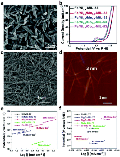 | ||
| Fig. 23 (a) SEM image and (b) LSV curves (for OER) of Fe/Ni-MOF nanorods. Reproduced with permission.265 Copyright 2018, Wiley-VCH. (c) SEM and (d) AFM images of Ni10Co-MIL-77 nanobelts. Tafel plots of Ni-MIL-77, Ni20Co-MIL-77, Ni10Co-MIL-77, Ni5Co-MIL-77 and Co-MIL-77 nanobelts for (e) OER and (f) ORR. Reproduced with permission.268 Copyright 2018, Wiley-VCH. | ||
Over the past decade, the applications and prospects of 2D MOFs in electrocatalysis have been highlighted by a large number of scientists and engineers. Compared to bulk MOFs, ultrathin 2D MOF nanostructures have long-term catalytic stability and superior electrocatalytic activity. For example, Duan et al.270 fabricated a NiFe-MOF nanoarray on different supports via the in situ growth strategy by adding organic ligands in the presence of the substrate through one-step electrolytic bath deposition (Fig. 24a). The nanosheets are hundred nanometres in transverse size with a smooth surface and uniform morphology (Fig. 24b). Surprisingly, these integrated 2D MOF electrodes exhibit superior bifunctional performances and strong durability in terms of OER, HER and overall water splitting. In the OER process, the actual active site is the metal-oxyhydroxy group formed by the transformation of the MOF in the catalytic process. NiO6 inside the MOF was oxidized into NiO6/NiOOH species as active centres, which then promote the oxidation of OH− into molecular oxygen. When used as both cathode and anode electrodes, the electrolytic cell can reach a current density of 10 mA cm−2 at a voltage of 1.55 V, which is 70 mV lower than that of the cell constructed with an IrO2 anode and a Pt/C cathode (Fig. 24c). In addition, Zhao et al.23 reported 2D NiCo bimetallic MOF nanosheets (NiCo-UMOFNs) that exhibited a high electrocatalytic activity for the OER (Fig. 24d–f). Under alkaline conditions, the initial potential of NiCo-UMOFNs loaded onto copper foam is 1.39 V at 10 mA cm−2, corresponding to an overpotential of 189 mV. A highly stable current density at a constant overpotential of 0.25 V is obtained for at least 200 h, and the associated faradaic efficiency reaches 99.3%. Moreover, the combination of X-ray absorption spectroscopy (XAS) experiments and density-functional theory (DFT) calculations was used to analyse the real active sites and catalytic mechanisms, illustrating the highly active performances of these UMOFNs in electrocatalysis applications.
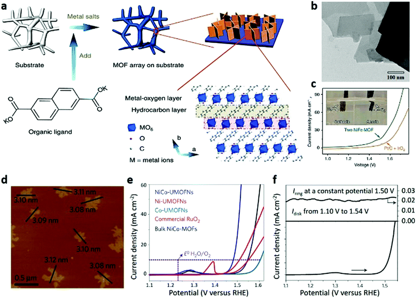 | ||
| Fig. 24 (a) Synthetic process, (b) TEM image and (c) LSV curves of 2D NiFe-MOF nanosheets. Reproduced with permission.270 Copyright 2017, Nature Publishing Group. (d) AFM image of NiCo-UMOFNs. (e) LSV curves of NiCo-UMOFNs, Ni-UMOFNs, Co-UMOFNs, commercial RuO2 and bulk NiCo-MOFs. (f) RRDE measurement of NiCo-UMOFNs at a rotation speed of 1500 rpm for OER. Reproduced with permission.23 Copyright 2016, Nature Publishing Group. | ||
Decreasing the thickness of the MOF nanosheets will increase their catalytic properties by improving the conductivity and exposing active sites of the electrodes. In this regard, Ni-M-MOF (M = Fe, Al, Co, Mn, Zn, and Cd) nanosheets with a thickness of only several atomic layers were prepared through a bottom-up method on a large scale, which exhibit a low overpotential of 221 mV at a current density of 10 mA cm−2 with a small Tafel slope of 56.0 mV dec−1. They also show excellent stability for at least 20 h without obvious activity decay.81
Apart from the 1D and 2D MOF nanostructures, 3D micro/nano MOFs and their composites have also received a rapidly growing interest for use in electrocatalysis.271 Sun et al.272 reported a facile and versatile preparation strategy of oriented nano/microstructure assisted controllable fabrication (ONACF), which is a useful approach for the fabrication of MOF membranes anchored on a nano/microstructure modified Ni foam substrate. The synthesized 3D Cu MOF with different amounts of nano CuS showed excellent ORR performances with an onset potential of 0.91 V vs. RHE. The kinetic current density of this catalyst is as large as 11.3 mA cm−2 at 0.55 V vs. RHE, showing a quasi-four-electron transfer pathway.
Among the various metal-based catalysts, cobalt-based MOFs are considered as promising candidates, such as ZIF-67, which is widely used as an excellent catalyst in electrochemistry. Owing to the uniform distribution of cobalt species in Co-MOFs, they can also be used as single atom catalysts.273–279 It is considered that the completely coordinated Co ion in ZIF-67 shows a low electrocatalytic performance. One way to improve the catalytic properties is to remove some of the attached ligands and create unsaturated metal sites (CUMSs) as catalytic centres for the OER280 (Fig. 25a–d). In addition to ZIF-67, Jiang et al.273 investigated the OER properties of the MOF [K(H2O)2Co3(cit)(Hcit)] (UTSA-16) that consists of mononuclear Co ions and Co4O4 cubane units. Attributed to its Co4O4 cubanes, high valence cobalt centres, and synergistic cooperation of the intrinsic open porous structure, UTSA-16 shows superior OER performances in alkaline solution. The experimental results indicate that UTSA-16 can gradually transform into catalytically active CoOx species during the OER process. To overcome the poor conductivity of MOFs, growing the MOF nanostructure on a conductive support is a facile strategy. In this regard, Wang et al.281 synthesized an M(Ni/Fe)-BTC MOF on nickel foam as an electrode and systematically investigated the catalytic performance through changing the metal contents and species (Fig. 25e–g). Owing to the conductive nickel foam substrate and the highly porous MOF film providing abundant active centres and a large accessible surface, and offering open channels for the diffusion and dissipation of the electrolyte and O2, the MOF film composites have good electrocatalytic activity with a low overpotential of 270 mV reaching 10 mA cm−2, a low Tafel slope and a high faradaic efficiency, as well as good stability (Fig. 25h). Although it is unstable especially in water, the paddle-wheel type cluster Co2-(RCOO)4(LT)2 (R = substituent group, LT = terminal ligand) possessing unusual metal coordination geometry compared with other cobalt compounds may display high catalytic activity. In this aspect, Shen et al.282 successfully used a modular synthesis method to immobilize the paddle-wheel type Co carboxylate cluster in a unique FeIII dicarboxylate skeleton, and the synthesized MOF hybrids exhibited extremely high OER catalytic activity.
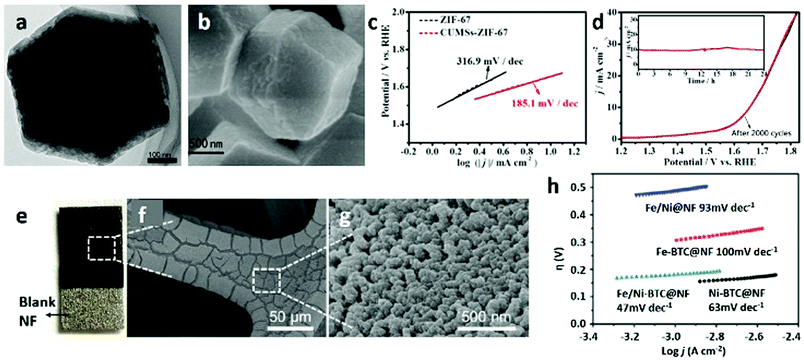 | ||
| Fig. 25 (a) TEM and (b) SEM images and (c) Tafel plots of CUMSs-ZIF-67 particles. (d) LSV curves of CUMSs-ZIF-67 particles in 0.5 M KBi (inset: time-dependent current density curves for CUMSs-ZIF-67 particles at 1.64 V VS. RHE). Reproduced with permission.280 Copyright 2017, Elsevier Ltd. (e) Optical and (f and g) SEM images of Fe/Ni-BTC@NF. (h) Tafel plots of Fe/Ni@NF, Fe-BTC@NF, Fe/Ni-BTC@NF (Ni foam) and Ni-BTC@NF for OER. Reproduced with permission.281 Copyright 2016, American Chemical Society. | ||
Through a LB approach, a 2D Ni-based supramolecular polymer single-layer sheet (H3[NiIII3(tht)2]) (tht = 1,2,5,6,9,10-triphenylenehexathiol) with a thickness of 0.7–0.9 nm was synthesized by Dong et al.283 This 2D MOF nanosheet shows remarkable electrocatalytic activity in the HER, with superior performances compared to those of most reported carbon-based electrocatalysts. The high degree of complexation between Ni and thiol groups plays a key role in the robust coupling of the THT monomers. With the pristine-graphene-templated growth strategy,45 the obtained 2D single-crystal MOF nanoplate (Fig. 26a and b), with a large lateral size of 23 μm corresponding to an aspect ratio as high as 1500, exhibits significant electrochemical performance for OER, and shows a small charge transfer resistance (Fig. 26c and d). Benefiting from the crystal dimensional reduction and the close contact with conductive supports, an observably enhanced electrocatalytic property is found in this MOF/graphene with 2D architecture, comparing with 2D MOFs prepared through the liquid exfoliation method or 2D MOFs physically coupled with an additional conductive network.
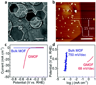 | ||
| Fig. 26 (a) TEM and (b) AFM images of graphene-templated H3[NiIII3(tht)2] nanoflakes. (c) LSV curves and (d) Tafel plots of the bulk MOF and graphene-templated H3[NiIII3(tht)2] nanoflakes for HER. Reproduced with permission.45 Copyright 2019, American Chemical Society. | ||
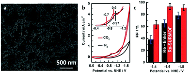 | ||
| Fig. 27 (a) SEM image of Re-SURMOF thin film on FTO substrates. (b) Cyclic voltammogram of Re-SURMOF-FTO at a scan rate of 100 mV s−1. (c) Faradaic efficiency of Re-SURMOF and Re-linker (0.5 mM) for CO2 reduction. Reproduced with permission.82 Copyright 2016, The Royal Society of Chemistry. | ||
Multiphase electrocatalysis can control the chemical environment of the active sites better and improve the performance of the catalysts.44,47,287 A 3D highly stable porphyrin-based MOF (PCN-222) has been used as a heterogeneous catalyst, exhibiting high catalytic performance for the electrochemical conversion of CO2 to CO, owing to the combination of good CO2 adsorption ability due to the large porosity and the intrinsic activity of the porphyrin molecule.288 Ion exchange in MOFs is a good strategy to develop highly active electrocatalysts. A single Ni-atom catalyst was prepared by ion exchange between Ni ions and Zn nodes within MOFs, displaying an excellent TON of 5273 h−1, with a faradaic efficiency for CO production of 71.9%.289 In addition to ion exchange, ligand doping is another route to improve the catalytic performance of MOFs for CO2 reduction. Very recently, a highly active catalyst for CO2RR was achieved by ligand doping in ZIF-8. The modified ZIF-8 exhibits an increased activity and faradaic efficiency compared with that of pristine ZIF-8. The DFT calculation results indicate that the sp2 C atoms in the imidazolate ligand adjacent to the introduced phenanthroline molecules exhibit a lower energy barrier for CO2 activation, which are the main active sites for this catalytic reaction.290
4 Conclusion and future outlook
In summary, this review provides an overview of the significant advances in the development of micro/nanoMOFs for electrochemical applications. Synthetic strategies for the morphology control of micro/nanoMOFs with 1D, 2D and 3D structures have been summarized. The utility of these MOF micro/nanostructures as electrode materials in batteries, SCs and electrocatalysis has also been discussed. Despite MOFs showing advantages including highly porous structures and controllable chemical compositions, it should be noted that the direct use of MOFs as electrode materials is still in its infancy stage and faces many challenges, especially the limited conductivity and stability of MOFs.Thermal and chemical stability is of great significance to the electrochemical applications of MOF materials. Compared with other electrode materials such as carbon-based materials and metal oxides, MOFs show relatively low stability, especially in basic/acidic aqueous conditions. In contrast, MOF-derived carbons, MOF-derived oxides, and their composites show promising prospects as electrode materials, while the high cost and low yields of the products are unfavourable for scalable production in practical applications. However, developing an efficient electrical device such as batteries or SCs is closely related to the electrode materials, separators and electrolytes. The rational design of the parts of electrical devices is the most efficient method to enhance their performances. For example, the stability of electrode materials, as a part of batteries or SCs, can be improved by rational design of the electrolyte. A suitable electrolyte might significantly enhance the stability of the MOF electrode and help to address the problem of stability suffered by MOF materials. Additionally, comprehensive considering the application environments of MOFs in electrochemistry depending on their inherent features is also important. MOFs consisting of variable-valence metal ions and redox-active ligands are suitable for LIBs/SIBs, while MOFs composed of Lewis acidic open metal sites and Lewis basic organic ligands are more conducive to sulfur storage and polysulfide confinement in the LSBs.
It is well-known that the most attractive aspect of MOFs is the high specific surface area and high porosity, which can alleviate volume variation, facilitate electrolyte penetration and enhance the utilization of active materials in batteries. However, in practical applications, the high porosity of electrode materials can result in a low volumetric energy density and CE. Thus, special attention should be paid to the adjustment of porosity of MOF electrodes to optimize the volumetric energy density, CE and rate capability.
The poor conductivity of MOFs is another issue that should be considered. Though some conductive MOF materials have been synthesized in recent years, they are still far from satisfactory when used as electrodes in batteries, SCs or electrocatalysis. Therefore, the combination of micro/nanoMOFs with special morphologies, such as 1D, 2D and 3D structures, with conductive materials including graphene, metal foams and other functional supports is a feasible approach, in which the supports can not only facilitate the fast transport of electrons and diffusion of the electrolyte, but also improve the durability and stability. It is considered that the functionalized modification by grafting desired atoms/groups onto either metal ions/clusters or organic linkers might also improve the conductivity or stability of MOF electrode materials. Owing to the great efforts made by researchers, some newly emerged conductive MOFs have also been achieved, which can greatly accelerate the development of the direct use of MOFs as electrodes in electrochemistry. Very recently, the use of conductive MOFs as a solid-state electrolyte in batteries has also emerged, which undoubtedly is a big progress in the application of MOFs in electrodevices.
Though significant progress has been achieved, the development of efficient and controllable approaches to the scalable synthesis of micro/nanoMOFs is still necessary. To date, micro/nanoMOFs with specific functionalities can only be fabricated on the laboratory scale, which is low-yielding and time-consuming. Further research should focus on the development of advanced technologies for synthesizing MOFs with controllable structure and composition, improving their stability and conductivity for electronic devices, revealing the relationships between the morphology and properties, and exploring the charge/discharge mechanism of MOF materials in electrochemical processes. Although these challenges are still existing, the rapid development of MOF science endows this kind of functional materials with a bright future in electrochemistry. Through sustained research efforts by MOF chemists and chemical engineers in this exciting field, practical application of MOFs to electrochemical processes may eventually be achieved (Tables 1–3).
| LIB | ||||||
|---|---|---|---|---|---|---|
| Sample | Morphology | Capacity retention/CN | RC/rate | CE% | CC/DC | Ref. |
| Capacity retention (mA h g−1); CN: cycle number; RC: reversible capacity (mA h g−1)/rate (mA g−1); CE: coulombic efficiency; CC: charge capacity (mA h g−1); DC: discharge capacity (mA h g−1); SA: BET surface area (m2 g−1); LC: limited capacity (mA h g−1); O2 adsorption (cm3 g−1). | ||||||
| CoHNta | Nanorod | 875/300 | 460/2400 | 65 | —/1405 | 127 |
| Co-BTC | Nanorod | 750/200 | 650/50 | 99 (199th) | 622/1739 (150th) | 227 |
| Mn2(NDC)2(DMF)2 | Microbar | — | 765.4/200 | 42.12 (initial) | 707.2/1679.0 (initial) | 228 |
| Cd2(NDC)2(DMF)2 | Microbar | — | 401.8/200 | 41.17 (initial) | 514.9/1241.4 (initial) | 228 |
| Fe-MIL-88B | Nanorod | 73.7%/100 (0.25C) | 744.5/60 | 63.0 (initial) | 819.2/1603.3 (initial) | 229 |
| Co2(DOBDC) | Microrod | 878.5/100 | 408.2/500 | 56 (initial) | 785/1409 (initial) | 230 |
| PCN-600 | Microneedle | — | 1300/400 | 49 (initial) | — | 231 |
| CPO-27 | Nanorod | 456/500 | 834/50 | 67 | 834/1248 (50 mA g−1) | 232 |
| CoCOP | Nanowire | 83%/300 (1C) | 1107/20 | 68.3 (initial) | — | 83 |
| Mn-BTC | Microrod | 83%/100 | — | 97 (initial) | 694/1717 (initial) | 134 |
| Asp-Cu | Nanofiber | — | 233/50 (200th) | 98.5 (200th) | — | 233 |
| Cu3(HHTP)2 | Nanosheet | 85/(20C) | — | 69.2 | — | 72 |
| Cu-TCA | Nanosheet | 70.9/200 | — | 96.5 (200th) | — | 102 |
| Ti-MOF | Microcube | 85%/500 | 527.12/100 | 85 (500th) | — | 177 |
| ILE@ZIF-67 | Microcube | 151/60 | — | 99 (60th) | — | 188 |
| H-Co-MOF | Microflower | — | 1345/100 | 66.7 | 1432/2147 (initial) | 160 |
| CuPcOH | Microparticle | 55% (70th) | — | 95 (200th) | 151/128 | 151 |
| FeHCCo | Nanocube | 42% (0.63C) | 136 (0.63C) | 99.6 | — | 159 |
| Cu-BTC | Microcube | 474/50 | 740/96 | 383 mA g−1 | 641/1497 (initial) | 234 |
| Ni-BTC | Microflower | — | 1085/100 | 96.4 (9th) | — | 150 |
| Al-FumAs | Nanosheet | 84.6%/3.75 A g−1 | 392/37.5 | 99.5 | — | 181 |
| Co2(OH)2BDC | Microcube | 85%/540 mA h g−1 | 650/50 | 99 (10th) | 458/468 (80th) | 139 |
| Li–S | ||||||
|---|---|---|---|---|---|---|
| Sample | Morphology | Capacity retention/CN | RC/rate | CE% | SA | Ref. |
| Mn-CCs–xH2O | Microparticle | 743/200 | 1145 | 79.8 | — | 201 |
| Cu-TDPAT | Microparticle | 745/500 | 745/1675 | — | — | 235 |
| Cu-BTC | Microparticle | 65%/20 | 679 (max) | — | — | 196 |
| MOF-525 | Microparticle | 400/5C | 700/0.5C | — | 2600 | 236 |
| PCN-224 | Microcube | 74% | 670 (1000th) | 99.7 | 2660 | 74 |
| Cu-MOF | Microcube | — | 1051.3/200 | 99.4 (300th) | 737.32 | 194 |
| Y-FTZB | Microcube | 557/300 | — | — | — | 73 |
| Sample | Morphology | SA | CD | SC | CR/CN | Electrolyte | Ref. |
|---|---|---|---|---|---|---|---|
| SA: BET surface area (m2 g−1); CD: current density (A g−1); SC: specific capacitance (F g−1); CR: capacity retention (%); CN: cycle number; electrolyte (KOH, M). | |||||||
| Ni@Cu-MOF | Microrod | 67.908 | 1 | 526 | 80/1200 | 6 | 242 |
| Co2(OH)2BDC | Nanosheet | — | 0.5 | 1159 | 96.7/6000 | 3 | 106 |
| Ni/Co-MOF | Nanoflake | — | 0.5 | 530.4 | No fading/2000 | 0.1 | 259 |
| Ni-MOF | Nanosheet | 436.06 | 2 | 1668.7 | 90.3/5000 | 3 | 241 |
| {[Co(Hmt)(tfbdc)(H2O)2]·(H2O)2}n | Nanoflake | 12.15 | 1 | 2474 | 94.3/200 | 1 | 252 |
| [Ni3(OH)2(C8H4O4)2(H2O)4]·2H2O | Nanosheet | — | 0.5 | 1127 | 90/3000 | 6 | 16 |
| Zn/Ni-MOF | Nanoflake | — | 0.25 | 1620 | 91/3000 | 6 | 260 |
| Co-MOF | Nanosheet | 48.9 | 1 | 2564 | 95.8/3000 | 5 | 101 |
| Ni(HBTC)(4,4′-bipy) | Microcube | — | 0.5 | 977.04 | 92.34/5000 | 3 | 257 |
| NiCo-MOF | Nanosheet | — | 1 | 339.3 | 70.3/2000 | 2 | 261 |
| Ni-MOF | Microparticle | 18.936 | 0.3 | 1017 | 93.5/1000 | 6 | 158 |
| CoNi-MOF | Microcube | 123.6 | 1 | 1300 | 71/3000 | 6 | 79 |
| Zn/Ni-MOF | Microcube | 126.0 | 1 | 237.4 | 88/4000 | 3 | 244 |
| OER | ||||||
|---|---|---|---|---|---|---|
| Sample | Morphology | E Onset | E j=10 | Tafel slope | Electrolyte | Ref. |
| E onset for onset potential (mV vs. RHE). Ej=10 for overpotential required for the current density of 10 mA cm−2 (mV vs. RHE). Tafel slope (mV dec−1). E1/2 = half-wave potential. Electrolyte (KOH, M). | ||||||
| PANI/ZIF-67 | Microparticle | — | 156 | 37 | 1 | 291 |
| Co4(BTC)3(BIM)6 | Microrod | — | 280 | 51 | 1 | 263 |
| NiCo-UMOFNs | Nanosheet | 142 | 250 | 42 | 1 | 23 |
List of acronyms and abbreviations
| SSAs | Specific surface areas |
| PCPs | Porous coordination polymers |
| ZIF | Zeolite imidazole frameworks |
| MW | Microwave assisted heating |
| HKUST-1 | Cu3(btc)2 |
| MIL-88A | Fe3O(fumarate)3 |
| MIL-88B-NH2 | (Fe3O(NH2-bdc)3 NH2-bdc = 2-amino-1,4-benzenedicarboxylate |
| MOF-5 | Zn4O(bdc)3 |
| IRMOF-3 | Zn4O(NH2-bdc)3 |
| Cu(II)-Asp | L-Aspartate |
| Ag(I)-Cys | Cysteine |
| NMOFs | Nanoscale metal–organic frameworks |
| MR | Magnetic resonance |
| EES | Electrical energy storage |
| EVs | Electrical vehicles |
| HOMO | Highest occupied molecular orbital |
| LUMO | Lowest unoccupied molecular orbital |
| SEI | Solid/electrolyte-interface |
| MIL-53 | FeIII(OH)0.8F0.2O2CC6H4CO2·H2O |
| XAFS | X-ray absorption fine structure |
| SBU | Secondary building unit |
| Cu(2,7-AQDC) | 2,7-H2AQDC = 2,7-anthraquinonedicarboxylic acid |
| AQ | Anthraquinone |
| HER | Hydrogen evolution reaction |
| OER | Oxygen evolution reaction |
| ORR | Oxygen reduction reaction |
| LbL | Layer-by-layer |
| LB | Langmuir–Blodgett |
| SAM | Self-assembled monolayer |
| Fe(py)2[Pt(CN)4] | py, pyridine |
| H2TCPP | 5,10,15,20-Tetrakis(4-carboxyphenyl)porphyrin |
| Cu-TCA | H3TCA = tricarboxytriphenyl amine |
| Mn-LCP | Mn-(tfbdc)(4,4′-bpy)(H2O)2 |
| H2tfbdc | Tetrafluoroterephthalic acid |
| EDLCs | Electrical double layer supercapacitors |
| THT | 1,2,5,6,9,10-Triphenylenehexathiol |
| bipy | 2,2′-Bipyridine |
| PCN-22(Fe) | [Zr6O8(OH)4(H2O)4][(TCPP-Fe-(III)-Cl)2] |
| TCPP | 4,4′,4′′,4′′′-(Porphyrin-5,10-15,20-tetrayl)tetrabenzoate |
| ReL(CO)3Cl | L = 2,2′-bipyridine-5,5′-dicarboxylic acid |
| TBAH | Tetrabutylammonium hydroxide |
| Ni3(HITP)2 | HITP = 2,3,6,7,10,11-hexaiminotriphenylene |
| EDLC | Electrochemical double layer capacitors |
| BDC | Benzenedicarboxylic acid |
| XAS | X-ray absorption spectra |
| DFT | Density functional theory |
| MSHMs | Multi-shelled hollow MOFs |
| MIL-177 | Zn4O, (1,3,5-benzenetribenzoate)2 |
| NTC | Ni-1,4,5,8-naphthalenetetracarboxylates |
| CoBTC | BTC = 1,3,5-benzenetricarboxylate |
| Co2(OH)2BDC | BDC = 1,4-benzenedicarboxylate |
| HNta | Nitrilotriacetic acid |
| NDC | 1,4-Naphthalene dicarboxylate |
| CPO-27 | 2,5-Dihydroxyterephthalic acid (H4Dobdc) |
| ILE | Ionic liquid electrolyte |
| FumAs | Fumarates |
| Zn(IM)1.5(abIM)0.5 | IM = imidazole |
| Ni-Me4bpz | C20H24Cl2N8Ni |
| Asp | Aspartic acid |
| Co-MOF-71 | Co(bdc)(DMF) |
| UTSA-16 | K(H2O)2Co3(cit)(Hcit) |
| CUMSs | Coordinately unsaturated metal sites |
| DBD | Dielectric barrier discharge |
| SSHM | Single-shelled hollow MOF |
| DSHM | Double-shelled hollow MOF |
| TSHM | Triple-shelled hollow MOF |
| NAHNs | Nanosheet assembled hollow nanocubes |
| DOBDC | 2,5-Dioxido-1,4-benzenedicarboxylate |
Conflicts of interest
There are no conflicts to declare.Acknowledgements
This work was supported by the National Natural Science Foundation of China (NSFC-21671170, 21673203, U1904215, and 21875207), the Top-notch Academic Programs Project of Jiangsu Higher Education Institutions (TAPP), Program for New Century Excellent Talents of the University in China (NCET-13-0645), the Six Talent Plan (2015-XCL-030), Qinglan Project of Jiangsu, Program for Colleges Natural Science Research in Jiangsu Province (18KJB150036) as well as the Science and Technology Innovation Foster Foundation of Yangzhou University (2016CXJ010) and Postgraduate Research & Practice Innovation Program of Jiangsu Province (KYCX19_2100). We also acknowledge the Priority Academic Program Development of Jiangsu Higher Education Institutions and the technical support we received at the Testing Center of Yangzhou University.Notes and references
- Z. B. Liang, C. Qu, D. G. Xia, R. Q. Zou and Q. Xu, Angew. Chem., Int. Ed., 2018, 57, 9604–9633 CrossRef CAS PubMed.
- C. L. Tan, X. H. Cao, X. J. Wu, Q. Y. He, J. Yang, X. Zhang, J. Z. Chen, W. Zhao, S. K. Han, G.-H. Nam, M. Sindoro and H. Zhang, Chem. Rev., 2017, 117, 6225–6331 CrossRef CAS PubMed.
- M. C. Lin, M. Gong, B. G. Lu, Y. P. Wu, D. Y. Wang, M. Y. Guan, M. Angell, C. X. Chen, J. Yang, B. J. Hwang and H. J. Dai, Nature, 2015, 520, 325–328 CrossRef PubMed.
- Q. Wang and D. Astruc, Chem. Rev., 2019 DOI:10.1021/acs.chemrev.9b00223.
- G. Y. Liu, Y. Sheng, J. W. Ager, M. Kraft and R. Xu, EnergyChem, 2019, 1, 100014 CrossRef.
- W. Liu, W. P. Lustig and J. Li, EnergyChem, 2019, 1, 100008 CrossRef.
- Y. Y. Dong, M. W. Zhou, W. Z. Tu, E. B. Zhu, Y. Chen, Y. Z. Zhao, S. J. Liao, Y. Huang, Q. Chen and Y. J. Li, Adv. Funct. Mater., 2019, 29, 1900015 CrossRef.
- Y. Pang, K. N. Zhang, Z. Yang, S. Jiang, Z. Y. Ju, Y. X. Li, X. F. Wang, D. Y. Wang, M. Q. Jian, Y. Y. Zhang, R. R. Liang, H. Tian, Y. Yang and T. L. Ren, ACS Nano, 2018, 12, 2346–2354 CrossRef CAS PubMed.
- H. Yang, K. Qi, L. Q. Gong, W. L. Liu, S. Zaman, X. P. Guo, Y. B. Qiu and B. Y. Xia, ACS Sustainable Chem. Eng., 2018, 6, 11408–11413 CrossRef CAS.
- D. Yoon, J. Lee, B. Seo, B. Kim, H. Baik, S. H. Joo and K. Lee, Small, 2017, 13, 1700052 CrossRef PubMed.
- C. Wang, X. S. Wang, Y. Yang, A. Kushima, J. T. Chen, Y. H. Huang and J. Li, Nano Lett., 2015, 15, 1796–1802 CrossRef CAS PubMed.
- Y. Pan, K. A. Sun, S. J. Liu, X. Cao, K. L. Wu, W. C. Cheong, Z. Chen, Y. Wang, Y. Li, Y. Q. Liu, D. S. Wang, Q. Peng, C. Chen and Y. D. Li, J. Am. Chem. Soc., 2018, 140, 2610–2618 CrossRef CAS PubMed.
- M. Bosch, S. Yuan, W. Rutledge and H.-C. Zhou, Acc. Chem. Res., 2017, 50, 857–865 CrossRef CAS PubMed.
- T. Y. Du, C. Q. Zhao, F. U. Rehman, L. M. Lai, X. Q. Li, Y. Sun, S. H. Luo, H. Jiang, N. Gu, M. Selke and X. M. Wang, Adv. Funct. Mater., 2017, 27, 1603926 CrossRef.
- Y.-P. Li, Y. Wang, Y.-Y. Xue, H.-P. Li, Q.-G. Zhai, S.-N. Li, Y.-C. Jiang, M.-C. Hu and X. Bu, Angew. Chem., Int. Ed., 2019, 58, 13590–13595 CrossRef CAS PubMed.
- J. Yang, P. X. Xiong, C. Zheng, H. Y. Qiu and M. D. Wei, J. Mater. Chem. A, 2014, 2, 16640–16644 RSC.
- D. Sheberla, J. C. Bachman, J. S. Elias, C.-J. Sun, Y. Shao-Horn and M. Dincă, Nat. Mater., 2017, 16, 220–224 CrossRef CAS PubMed.
- J. Hao, X. Li, X. Song and Z. Guo, EnergyChem, 2019, 1, 100004 CrossRef.
- M. Yan, W.-P. Wang, Y.-X. Yin, L.-J. Wan and Y.-G. Guo, EnergyChem, 2019, 1, 100002 CrossRef.
- W. L. Zhang, F. Zhang, F. W. Ming and H. N. Alshareef, EnergyChem, 2019, 1, 100012 CrossRef.
- P. Horcajada, R. Gref, T. Baati, P. K. Allan, G. Maurin, P. Couvreur, G. Férey, R. E. Morris and C. Serre, Chem. Rev., 2012, 112, 1232–1268 CrossRef CAS PubMed.
- H. Li, L. B. Li, R.-B. Lin, W. Zhou, Z. J. Zhang, S. C. Xiang and B. L. Chen, EnergyChem, 2019, 1, 100006 CrossRef.
- S. L. Zhao, Y. Wang, J. C. Dong, C.-T. He, H. J. Yin, P. F. An, K. Zhao, X. F. Zhang, C. Gao, L. J. Zhang, J. W. Lv, J. J. Wang, J. Q. Zhang, A. M. Khattak, N. A. Khan, Z. X. Wei, J. Zhang, S. Q. Liu, H. J. Zhao and Z. Y. Tang, Nat. Energy, 2016, 1, 16184 CrossRef CAS.
- K. Cho, S. H. Han and M. P. Suh, Angew. Chem., Int. Ed., 2016, 128, 15527–15531 CrossRef.
- S. Zhang, Y. X. Zhao, R. Shi, G. I. N. Waterhouse and T. R. Zhang, EnergyChem, 2019, 1, 100013 CrossRef.
- R. B. Zhao, H. T. Xie, L. Chang, X. X. Zhang, X. J. Zhu, X. Tong, T. Wang, Y. L. Luo, P. P. Wei, Z. M. Wang and X. P. Sun, EnergyChem, 2019, 1, 100011 CrossRef.
- L.-F. Chen and Q. Xu, Science, 2017, 358, 304–305 CrossRef CAS PubMed.
- F.-L. Li, Q. Shao, X. Q. Huang and J.-P. Lang, Angew. Chem., Int. Ed., 2018, 57, 1888–1892 CrossRef CAS PubMed.
- L. Jiao, Y. Wang, H.-L. Jiang and Q. Xu, Adv. Mater., 2018, 30, 1703663 CrossRef PubMed.
- G. Zhan and H. C. Zeng, Adv. Funct. Mater., 2016, 26, 3268–3281 CrossRef CAS.
- G. Zhan and H. C. Zeng, Nat. Commun., 2018, 9, 3778 CrossRef PubMed.
- M. A. Syzgantseva, C. P. Ireland, F. M. Ebrahim, B. Smit and O. A. Syzgantseva, J. Am. Chem. Soc., 2019, 141, 6271–6278 CrossRef CAS PubMed.
- L. Feng, J.-L. Li, G. S. Day, X.-L. Lv and H.-C. Zhou, Chem, 2019, 5, 1265–1274 CAS.
- T. Liu, P. Li, N. Yao, T. Kong, G. Cheng, S. L. Chen and W. Luo, Adv. Mater., 2019, 31, 1806672 CrossRef PubMed.
- E. M. Larsson, C. Langhammer, I. Zoric and B. Kasemo, Science, 2009, 326, 1091–1094 CrossRef CAS PubMed.
- H. G. Yang, C. H. Sun, S. Z. Qiao, J. Zou, G. Liu, S. C. Smith, H. M. Cheng and G. Q. Lu, Nature, 2008, 453, 638–641 CrossRef CAS PubMed.
- X. R. Li, H. G. Xue and H. Pang, Nanoscale, 2017, 9, 216–222 RSC.
- D. M. Chen, N. N. Zhang, J. Y. Tian, C. S. Liu and M. Du, J. Mater. Chem. A., 2017, 5, 4861–4867 RSC.
- M. Chen, B. H. Wu, J. Yang and N. F. Zheng, Adv. Mater., 2012, 24, 862–879 CrossRef CAS PubMed.
- G. Liu, H. G. Yang, J. Pan, Y. Q. Yang, G. Q. M. Lu and H.-M. Cheng, Chem. Rev., 2014, 114, 9559–9612 CrossRef CAS PubMed.
- D. Shi, R. Zheng, M. J. Sun, X. Cao, C. X. Sun, C. J. Cui, C. S. Liu, J. Zhao and M. Du, Angew. Chem., Int. Ed., 2017, 56, 14637–14641 CrossRef CAS PubMed.
- L. L. Zou, C.-C. Hou, Z. Liu, H. Pang and Q. Xu, J. Am. Chem. Soc., 2018, 140, 15393–15401 CrossRef CAS PubMed.
- R. C. Arbulu, Y.-B. Jiang, E. J. Peterson and Y. Qin, Angew. Chem., Int. Ed., 2018, 57, 5813–5817 CrossRef CAS PubMed.
- C. H. Huang, J. C. Dong, W. M. Sun, Z. J. Xue, J. Ma, L. R. Zheng, C. Liu, X. Li, K. Zhou, X. Z. Qiao, Q. Song, W. D. Ma, L. Zhang, Z. Y. Lin and T. Wang, Nat. Commun., 2019, 10, 2779 CrossRef PubMed.
- A. Q. Hu, Q. Q. Pang, C. Tang, J. X. Bao, H. Q. Liu, K. Ba, S. H. Xie, J. Chen, J. J. Chen, Y. W. Yue, Y. Tang, Q. W. Li and Z. Z. Sun, J. Am. Chem. Soc., 2019, 141, 11322–11327 CrossRef CAS PubMed.
- L. L. Zou, M. Kitta, J. H. Hong, K. Suenaga, N. Tsumori, Z. Liu and Q. Xu, Adv. Mater., 2019, 31, 1900440 CrossRef PubMed.
- D. Yang and B. C. Gates, ACS Catal., 2019, 9, 1779–1798 CrossRef CAS.
- M. T. Zhao, Q. P. Lu, Q. L. Ma and H. Zhang, Small Methods, 2017, 1, 1600030 CrossRef.
- S. Z. Li and F. W. Huo, Nanoscale, 2015, 7, 7482–7501 RSC.
- L. Y. Chen, R. Luque and Y. W. Li, Chem. Soc. Rev., 2017, 46, 4614–4630 RSC.
- N. Stock and S. Biswas, Chem. Rev., 2012, 112, 933–969 CrossRef CAS PubMed.
- L. Wang, Y. Z. Han, X. Feng, J. W. Zhou, P. F. Qi and B. Wang, Coord. Chem. Rev., 2016, 307, 361–381 CrossRef CAS.
- K. Ariga, V. Malgras, Q. M. Ji, M. B. Zakaria and Y. Yamauchi, Coord. Chem. Rev., 2016, 320-321, 139–152 CrossRef CAS.
- A. Morozan and F. Jaouen, Energy Environ. Sci., 2012, 5, 9269 RSC.
- J. Aguilera-Sigalat and D. Bradshaw, Coord. Chem. Rev., 2016, 307, 267–291 CrossRef CAS.
- E. A. Flügel, A. Ranft, F. Haase and B. V. Lotsch, J. Mater. Chem., 2012, 22, 10119 RSC.
- X. W. Liu, T. J. Sun, J. L. Hu and S. D. Wang, J. Mater. Chem. A, 2016, 4, 3584–3616 RSC.
- S.-L. Li and Q. Xu, Energy Environ. Sci., 2013, 6, 1656 RSC.
- J. P. Lei, R. C. Qian, P. H. Ling, L. Cui and H. X. Ju, TrAC, Trends Anal. Chem., 2014, 58, 71–78 CrossRef CAS.
- J. K. Sun and Q. Xu, Energy Environ. Sci., 2014, 7, 2071 RSC.
- S. S. Zheng, X. R. Li, B. Y. Yan, Q. Hu, Y. X. Xu, X. Xiao, H. G. Xue and H. Pang, Adv. Energy Mater., 2017, 7, 1602733 CrossRef.
- Y. X. Xu, S. S. Zheng, H. Tang, X. T. Guo, H. G. Xue and H. Pang, Energy Storage Mater., 2017, 9, 11–30 CrossRef.
- L. Zhang, S. S. Zheng, L. Wang, H. Tang, H. G. Xue, G. X. Wang and H. Pang, Small, 2017, 13, 1700917 CrossRef PubMed.
- Z. B. Liang, R. Zhao, T. J. Qiu, R. Q. Zou and Q. Xu, EnergyChem, 2019, 1, 100001 CrossRef.
- Q. H. Yang, Q. Xu and H.-L. Jiang, Chem. Soc. Rev., 2017, 46, 4774–4808 RSC.
- H.-L. Jiang and Q. Xu, Chem. Commun., 2011, 47, 3351 RSC.
- G. Y. Xu, P. Nie, H. Dou, B. Ding, L. Y. Li and X. G. Zhang, Mater. Today, 2017, 20, 191–209 CrossRef CAS.
- X. J. Zhan, Z. Chen and Q. C. Zhang, J. Mater. Chem. A, 2017, 5, 14463–14479 RSC.
- R. Q. Zou and Q. Xu, Energy Environ. Sci., 2015, 8, 1837–1866 RSC.
- Q. L. Zhu and Q. Xu, Chem. Soc. Rev., 2014, 43, 5468–5512 RSC.
- H. L. Wang, Q.-L. Zhu, R. Q. Zou and Q. Xu, Chem, 2017, 2, 52–80 CAS.
- S. N. Gu, Z. W. Bai, S. Majumder, B. L. Huang and G. H. Chen, J. Power Sources, 2019, 429, 22–29 CrossRef CAS.
- M. L. Li, Y. Wan, J.-K. Huang, A. H. Assen, C.-E. Hsiung, H. Jiang, Y. Han, M. Eddaoudi, Z. P. Lai, J. Ming and L.-J. Li, ACS Energy Lett., 2017, 2, 2362–2367 CrossRef CAS.
- H. Q. Jiang, X.-C. Liu, Y. S. Wu, Y. F. Shu, X. Gong, F.-S. Ke and H. X. Deng, Angew. Chem., Int. Ed., 2018, 57, 3916–3921 CrossRef CAS PubMed.
- S. H. Kim, Y. J. Lee, D. H. Kim and Y. J. Lee, ACS Appl. Mater. Interfaces, 2018, 10, 660–667 CrossRef CAS PubMed.
- W. J. Yan, Z. Y. Guo, H. S. Xu, Y. B. Lou, J. X. Chen and Q. W. Li, Mater. Chem. Front., 2017, 1, 1324–1330 RSC.
- X. D. Xiang, K. Zhang and J. Chen, Adv. Mater., 2015, 27, 5343–5364 CrossRef CAS PubMed.
- J. P. Li, H. Y. Zhao, J. W. Wang, N. Li, M. M. Wu, Q. Zhang and Y. P. Du, Nano Energy, 2019, 62, 876–882 CrossRef CAS.
- J. Wang, Q. Zhong, Y. H. Xiong, D. Y. Cheng, Y. Q. Zeng and Y. F. Bu, Appl. Surf. Sci., 2019, 483, 1158–1165 CrossRef CAS.
- J. Huang, Y. Li, R.-K. Huang, C.-T. He, L. Gong, Q. Hu, L. S. Wang, Y.-T. Xu, X.-Y. Tian, S.-Y. Liu, Z.-M. Ye, F. X. Wang, D.-D. Zhou, W.-X. Zhang and J.-P. Zhang, Angew. Chem., Int. Ed., 2018, 57, 4632–4636 CrossRef CAS PubMed.
- F. L. Li, P. T. Wang, X. Q. Huang, D. J. Young, H. F. Wang, P. Braunstein and J. P. Lang, Angew. Chem., Int. Ed., 2019, 58, 7051–7056 CrossRef CAS PubMed.
- L. Ye, J. X. Liu, Y. Gao, C. H. Gong, M. Addicoat, T. Heine, C. Wöll and L. C. Sun, J. Mater. Chem. A, 2016, 4, 15320–15326 RSC.
- H. W. Song, L. S. Shen, J. Wang and C. X. Wang, J. Mater. Chem. A, 2016, 4, 15411–15419 RSC.
- T. Tsuruoka, S. Furukawa, Y. Takashima, K. Yoshida, S. Isoda and S. Kitagawa, Angew. Chem., Int. Ed., 2009, 48, 4739–4743 CrossRef CAS PubMed.
- W. J. Rieter, K. M. L. Taylor, H. Y. An, W. L. Lin and W. B. Lin, J. Am. Chem. Soc., 2006, 128, 9024–9025 CrossRef CAS.
- J. Puigmartí-Luis, M. Rubio-Martínez, U. Hartfelder, I. Imaz, D. Maspoch and P. S. Dittrich, J. Am. Chem. Soc., 2011, 133, 4216–4219 CrossRef.
- J. B. Shi, J. L. Zhang, D. X. Tan, X. Y. Cheng, X. N. Tan, B. X. Zhang, B. X. Han, L. F. Liu, F. Y. Zhang, M. R. Liu and J. F. Xiang, ChemCatChem, 2019, 11, 2058–2062 CrossRef CAS.
- D. M. Jiang, A. D. Burrows and K. J. Edler, CrystEngComm, 2011, 13, 6916–6919 RSC.
- A. Umemura, S. Diring, S. Furukawa, H. Uehara, T. Tsuruoka and S. Kitagawa, J. Am. Chem. Soc., 2011, 133, 15506–15513 CrossRef CAS PubMed.
- P. Pachfule, D. Shinde, M. Majumder and Q. Xu, Nat. Chem., 2016, 8, 718–724 CrossRef CAS.
- J. F. Yao, M. He, K. Wang, R. Z. Chen, Z. X. Zhong and H. T. Wang, CrystEngComm, 2013, 15, 3601 RSC.
- X. X. Fan, W. Wang, W. Li, J. W. Zhou, B. Wang, J. Zheng and X. G. Li, ACS Appl. Mater. Interfaces, 2014, 6, 14994–14999 CrossRef CAS.
- T. T. Xing, Y. B. Lou, Q. L. Bao and J. X. Chen, CrystEngComm, 2014, 16, 8994–9000 RSC.
- R. Li, Y.-P. Yuan, L.-G. Qiu, W. Zhang and J.-F. Zhu, Small, 2012, 8, 225–230 CrossRef CAS.
- Q. Li, W. Zhu, Y. B. Lian, Y. Peng and Z. Deng, Chin. Chem. Lett., 2019 DOI:10.1016/j.cclet.2019.05.005.
- R. Ameloot, L. Pandey, M. Van der Auweraer, L. Alaerts, B. F. Sels and D. E. De Vos, Chem. Commun., 2010, 46, 3735 RSC.
- S. Sakaida, K. Otsubo, O. Sakata, C. Song, A. Fujiwara, M. Takata and H. Kitagawa, Nat. Chem., 2016, 8, 377–383 CrossRef CAS.
- Y. Liu, Y. J. Ban and W. S. Yang, Adv. Mater., 2017, 29, 1606949 CrossRef.
- M. T. Zhao, Y. X. Wang, Q. L. Ma, Y. Huang, X. Zhang, J. F. Ping, Z. C. Zhang, Q. P. Lu, Y. F. Yu, H. Xu, Y. L. Zhao and H. Zhang, Adv. Mater., 2015, 27, 7372–7378 CrossRef CAS.
- Y. W. Peng, Y. Huang, Y. H. Zhu, B. Chen, L. Y. Wang, Z. C. Lai, Z. C. Zhang, M. T. Zhao, C. L. Tan, N. L. Yang, F. W. Shao, Y. Han and H. Zhang, J. Am. Chem. Soc., 2017, 139, 8698–8704 CrossRef CAS.
- J. Yang, Z. H. Ma, W. X. Gao and M. D. Wei, Chem. – Eur. J., 2017, 23, 631–636 CrossRef CAS.
- Z. Peng, X. H. Yi, Z. X. Liu, J. Shang and D. Y. Wang, ACS Appl. Mater. Interfaces, 2016, 8, 14578–14585 CrossRef CAS.
- P.-Z. Li, Y. Maeda and Q. Xu, Chem. Commun., 2011, 47, 8436 RSC.
- O. Shekhah, H. Wang, M. Paradinas, C. Ocal, B. Schüpbach, A. Terfort, D. Zacher, R. A. Fischer and C. Wöll, Nat. Mater., 2009, 8, 481–484 CrossRef CAS.
- R. Makiura, S. Motoyama, Y. Umemura, H. Yamanaka, O. Sakata and H. Kitagawa, Nat. Mater., 2010, 9, 565–571 CrossRef CAS.
- Y. Zheng, S. S. Zheng, Y. X. Xu, H. G. Xue, C. S. Liu and H. Pang, Chem. Eng. J., 2019, 373, 1319–1328 CrossRef CAS.
- G. D. Wu, J. H. Huang, Y. Zang, J. He and G. Xu, J. Am. Chem. Soc., 2017, 139, 1360–1363 CrossRef CAS.
- X. J. Bai, D. Chen, L. L. Li, L. Shao, W. X. He, H. Chen, Y. N. Li, X. M. Zhang, L. Y. Zhang, T. Q. Wang, Y. Fu and W. Qi, ACS Appl. Mater. Interfaces, 2018, 10, 25960–25966 CrossRef CAS.
- Y. X. Wang, M. T. Zhao, J. F. Ping, B. Chen, X. H. Cao, Y. Huang, C. L. Tan, Q. L. Ma, S. X. Wu, Y. Y. Yu, Q. P. Lu, J. Z. Chen, W. Zhao, Y. Y. Ying and H. Zhang, Adv. Mater., 2016, 28, 4149–4155 CrossRef CAS PubMed.
- K. M. Zhao, S. Q. Liu, G. Y. Ye, Q. M. Gan, Z. Zhou and Z. He, J. Mater. Chem. A, 2018, 6, 2166–2175 RSC.
- R. Ameloot, F. Vermoortele, W. Vanhove, M. B. J. Roeffaers, B. F. Sels and D. E. De Vos, Nat. Chem., 2011, 3, 382–387 CrossRef CAS.
- Y. Peng, Y. Li, Y. Ban, H. Jin, W. Jiao, X. Liu and W. Yang, Science, 2014, 346, 1356–1359 CrossRef CAS.
- M. M. Yuan, R. Wang, W. B. Fu, L. Lin, Z. M. Sun, X. G. Long, S. T. Zhang, C. Y. Nan, G. B. Sun, H. F. Li and S. L. Ma, ACS Appl. Mater. Interfaces, 2019, 11, 11403–11413 CrossRef CAS.
- Y. J. Ding, Y.-P. Chen, X. L. Zhang, L. Chen, Z. H. Dong, H.-L. Jiang, H. X. Xu and H.-C. Zhou, J. Am. Chem. Soc., 2017, 139, 9136–9139 CrossRef CAS.
- T. Rodenas, I. Luz, G. Prieto, B. Seoane, H. Miro, A. Corma, F. Kapteijn, F. X. Llabrés i Xamena and J. Gascon, Nat. Mater., 2015, 14, 48–55 CrossRef CAS.
- A. J. Clough, J. M. Skelton, C. A. Downes, A. A. de la Rosa, J. W. Yoo, A. Walsh, B. C. Melot and S. C. Marinescu, J. Am. Chem. Soc., 2017, 139, 10863–10867 CrossRef CAS.
- H. K. Arslan, O. Shekhah, D. C. F. Wieland, M. Paulus, C. Sternemann, M. A. Schroer, S. Tiemeyer, M. Tolan, R. A. Fischer and C. Wöll, J. Am. Chem. Soc., 2011, 133, 8158–8161 CrossRef CAS.
- O. Shekhah, H. Wang, S. Kowarik, F. Schreiber, M. Paulus, M. Tolan, C. Sternemann, F. Evers, D. Zacher, R. A. Fischer and C. Wöll, J. Am. Chem. Soc., 2007, 129, 15118–15119 CrossRef CAS.
- B. Liu, O. Shekhah, H. K. Arslan, J. Liu, C. Wöll and R. A. Fischer, Angew. Chem., Int. Ed., 2012, 51, 807–810 CrossRef CAS.
- K. Otsubo, T. Haraguchi, O. Sakata, A. Fujiwara and H. Kitagawa, J. Am. Chem. Soc., 2012, 134, 9605–9608 CrossRef CAS PubMed.
- S. Motoyama, R. Makiura, O. Sakata and H. Kitagawa, J. Am. Chem. Soc., 2011, 133, 5640–5643 CrossRef CAS.
- G. Xu, T. Yamada, K. Otsubo, S. Sakaida and H. Kitagawa, J. Am. Chem. Soc., 2012, 134, 16524–16527 CrossRef CAS.
- Y.-S. Li, H. Bux, A. Feldhoff, G.-L. Li, W.-S. Yang and J. Caro, Adv. Mater., 2010, 22, 3322–3326 CrossRef CAS PubMed.
- L. Wang, Y. Lu, J. Liu, M. Xu, J. Cheng, D. Zhang and J. B. Goodenough, Angew. Chem., Int. Ed., 2013, 52, 1964–1967 CrossRef CAS.
- V. Rubio-Giménez, S. Tatay, F. Volatron, F. J. Martínez-Casado, C. Martí-Gastaldo and E. Coronado, J. Am. Chem. Soc., 2016, 138, 2576–2584 CrossRef.
- A. Gallego, C. Hermosa, O. Castillo, I. Berlanga, C. J. Gõmez-García, E. Mateo-Martí, J. I. Martínez, F. Flores, C. Gõmez-Navarro, J. Gõmez-Herrero, S. Delgado and F. Zamora, Adv. Mater., 2013, 25, 2141–2146 CrossRef CAS PubMed.
- C. Li, Q. Yang, M. Shen, J. Y. Ma and B. W. Hu, Energy Storage Mater., 2018, 14, 82–89 CrossRef.
- J. C. Cui, N. Gao, X. P. Yin, W. L. Zhang, Y. Liang, L. Tian, K. Zhou, S. Q. Wang and G. T. Li, Nanoscale, 2018, 10, 9192–9198 RSC.
- W. X. Liu, J. J. Huang, Q. Yang, S. J. Wang, X. M. Sun, W. N. Zhang, J. F. Liu and F. W. Huo, Angew. Chem., Int. Ed., 2017, 56, 5512–5516 CrossRef CAS.
- X. T. Guo, S. S. Zheng, G. X. Zhang, X. Xiao, X. R. Li, Y. X. Xu, H. G. Xue and H. Pang, Energy Storage Mater., 2017, 9, 150–169 CrossRef.
- M. Hu, Y. Ju, K. Liang, T. Suma, J. W. Cui and F. Caruso, Adv. Funct. Mater., 2016, 26, 5827–5834 CrossRef CAS.
- A. Carné-Sánchez, I. Imaz, M. Cano-Sarabia and D. Maspoch, Nat. Chem., 2013, 5, 203–211 CrossRef.
- Y. Luo, M. Ahmad, A. Schug and M. Tsotsalas, Adv. Mater., 2019, 31, 1901744 CrossRef.
- S. Maiti, A. Pramanik, U. Manju and S. Mahanty, ACS Appl. Mater. Interfaces, 2015, 7, 16357–16363 CrossRef CAS.
- C. Li, X. S. Hu, X. B. Lou, L. J. Zhang, Y. Wang, J.-P. Amoureux, M. Shen, Q. Chen and B. W. Hu, J. Mater. Chem. A, 2016, 4, 16245–16251 RSC.
- C. Li, X. B. Lou, M. Shen, X. S. Hu, Z. Guo, Y. Wang, B. W. Hu and Q. Chen, ACS Appl. Mater. Interfaces, 2016, 8, 15352–15360 CrossRef CAS.
- Y. X. Tang, C. L. He, L. A. Mitchell, D. A. Parrish and J. M. Shreeve, Angew. Chem., Int. Ed., 2016, 55, 5565–5567 CrossRef CAS.
- Y. Wang, L. Wang, W. Huang, T. Zhang, X. Y. Hu, J. A. Perman and S. Q. Ma, J. Mater. Chem. A, 2017, 5, 8385–8393 RSC.
- L. Gou, L. M. Hao, Y.-X. Shi, S. L. Ma, X. Y. Fan, L. Xu, D. L. Li and K. Wang, J. Solid State Chem., 2014, 210, 121–124 CrossRef CAS.
- M. L. Pang, A. J. Cairns, Y. L. Liu, Y. Belmabkhout, H. C. Zeng and M. Eddaoudi, J. Am. Chem. Soc., 2013, 135, 10234–10237 CrossRef CAS.
- J. Huo, L. Wang, E. Irran, H. J. Yu, J. M. Gao, D. S. Fan, B. Li, J. J. Wang, W. J. Ding, A. M. Amin, C. Li and L. Ma, Angew. Chem., Int. Ed., 2010, 49, 9237–9241 CrossRef CAS PubMed.
- C. Avci, J. Ariñez-Soriano, A. Carné-Sánchez, V. Guillerm, C. Carbonell, I. Imaz and D. Maspoch, Angew. Chem., Int. Ed., 2015, 54, 14417–14421 CrossRef CAS.
- D. Li, S.-H. Yu and H.-L. Jiang, Adv. Mater., 2018, 30, 1707377 CrossRef.
- Q. Yang, C.-C. Yang, C.-H. Lin and H.-L. Jiang, Angew. Chem., Int. Ed., 2019, 58, 3511–3515 CrossRef CAS.
- F.-M. Zhang, J.-L. Sheng, Z.-D. Yang, X.-J. Sun, H.-L. Tang, M. Lu, H. Dong, F.-C. Shen, J. Liu and Y.-Q. Lan, Angew. Chem., Int. Ed., 2018, 57, 12106–12110 CrossRef CAS.
- Y. W. Peng, M. T. Zhao, B. Chen, Z. C. Zhang, Y. Huang, F. N. Dai, Z. C. Lai, X. Y. Cui, C. L. Tan and H. Zhang, Adv. Mater., 2018, 30, 1705454 CrossRef.
- Y. C. Tan and H. C. Zeng, Adv. Funct. Mater., 2017, 27, 1703765 CrossRef.
- K. Shen, L. Zhang, X. D. Chen, L. M. Liu, D. L. Zhang, Y. Han, J. Y. Chen, J. L. Long, R. Luque, Y. W. Li and B. L. Chen, Science, 2018, 359, 206–210 CrossRef CAS.
- Y. S. Wei, M. Zhang, M. Kitta, Z. Liu, S. Horike and Q. Xu, J. Am. Chem. Soc., 2019, 141, 7906–7916 CrossRef CAS PubMed.
- Q. M. Gan, H. N. He, K. M. Zhao, Z. He and S. Q. Liu, J. Colloid Interface Sci., 2018, 530, 127–136 CrossRef CAS.
- H. Nagatomi, N. Yanai, T. Yamada, K. Shiraishi and N. Kimizuka, Chem. – Eur. J., 2018, 24, 1806–1810 CrossRef CAS.
- Z. G. Jiang, T. F. Liu, L. J. Yan, J. Liu, F. F. Dong, M. Ling, C. D. Liang and Z. Lin, Energy Storage Mater., 2018, 11, 267–273 CrossRef.
- A. R. Tao, S. Habas and P. Yang, Small, 2008, 4, 310–325 CrossRef CAS.
- W. W. Yu, Y. A. Wang and X. Peng, Chem. Mater., 2003, 15, 4300–4308 CrossRef CAS.
- M. Eddaoudi, Science, 2002, 295, 469–472 CrossRef CAS.
- N. Sharma, S. Szunerits, R. Boukherroub, R. Ye, S. Melinte, M. O. Thotiyl and S. Ogale, ACS Appl. Energy Mater., 2019, 2, 4450–4457 CrossRef CAS.
- Y. Zhou, M. K. Wu, Y. L. Luo, B. C. Pang, X. R. Su, M. J. Zhou and L. Han, New J. Chem., 2019, 43, 1710–1715 RSC.
- M. Azadfalah, A. Sedghi and H. Hosseini, J. Mater. Sci.: Mater. Electron., 2019, 30, 12351–12363 CrossRef CAS.
- K. Zhang, R. S. Varma, H. W. Jang, J.-W. Choi and M. Shokouhimehr, J. Alloys Compd., 2019, 791, 911–917 CrossRef CAS.
- L. Chen, W. J. Yang, J. B. Wang, C. R. Chen and M. D. Wei, Chem. – Eur. J., 2018, 24, 13362–13367 CrossRef CAS.
- J. B. Goodenough and Y. Kim, Chem. Mater., 2010, 22, 587–603 CrossRef CAS.
- G. Férey, F. Millange, M. Morcrette, C. Serre, M.-L. Doublet, J.-M. Grenèche and J.-M. Tarascon, Angew. Chem., Int. Ed., 2007, 46, 3259–3263 CrossRef PubMed.
- C. Serre, F. Millange, C. Thouvenot, M. Noguès, G. Marsolier, D. Louër and G. Férey, J. Am. Chem. Soc., 2002, 124, 13519–13526 CrossRef CAS PubMed.
- C. Combelles, M. Ben Yahia, L. Pedesseau and M.-L. Doublet, J. Power Sources, 2011, 196, 3426–3432 CrossRef CAS.
- A. Fateeva, P. Horcajada, T. Devic, C. Serre, J. Marrot, J. Grenèche, M. Morcrette, J. Tarascon, G. Maurin and G. Férey, Eur. J. Inorg. Chem., 2010, 3789–3794 CrossRef CAS.
- Z. Y. Zhang, H. Yoshikawa and K. Awaga, J. Am. Chem. Soc., 2014, 136, 16112–16115 CrossRef CAS.
- J. Shin, M. Kim, J. Cirera, S. Chen, G. J. Halder, T. A. Yersak, F. Paesani, S. M. Cohen and Y. S. Meng, J. Mater. Chem. A, 2015, 3, 4738–4744 RSC.
- A. Nagai, X. Chen, X. Feng, X. S. Ding, Z. Q. Guo and D. L. Jiang, Angew. Chem., Int. Ed., 2013, 52, 3770–3774 CrossRef CAS.
- K. Saravanan, M. Nagarathinam, P. Balaya and J. J. Vittal, J. Mater. Chem., 2010, 20, 8329 RSC.
- T. D. Bennett, S. Cao, J. C. Tan, D. A. Keen, E. G. Bithell, P. J. Beldon, T. Friscic and A. K. Cheetham, J. Am. Chem. Soc., 2011, 133, 14546–14549 CrossRef CAS PubMed.
- T. Friščić, I. Halasz, P. J. Beldon, A. M. Belenguer, F. Adams, S. A. J. Kimber, V. Honkimäki and R. E. Dinnebier, Nat. Chem., 2012, 5, 66–73 CrossRef PubMed.
- P. J. Beldon, L. Fábián, R. S. Stein, A. Thirumurugan, A. K. Cheetham and T. Friščić, Angew. Chem., Int. Ed., 2010, 49, 9640–9643 CrossRef CAS PubMed.
- S. Tanaka, K. Kida, T. Nagaoka, T. Ota and Y. Miyake, Chem. Commun., 2013, 49, 7884 RSC.
- M. Armand, S. Grugeon, H. Vezin, S. Laruelle, P. Ribière, P. Poizot and J.-M. Tarascon, Nat. Mater., 2009, 8, 120–125 CrossRef CAS PubMed.
- S. Dühnen, R. Nölle, J. Wrogemann, M. Winter and T. Placke, J. Electrochem. Soc., 2019, 166, A5474–A5482 CrossRef.
- Q. Liu, L. L. Yu, Y. Wang, Y. Z. Ji, J. Horvat, M.-L. Cheng, X. Y. Jia and G. X. Wang, Inorg. Chem., 2013, 52, 2817–2822 CrossRef CAS.
- S.-B. Xia, S.-W. Yu, L.-F. Yao, F.-S. Li, X. Li, F.-X. Cheng, X. Shen, C.-K. Sun, H. Guo and J.-J. Liu, Electrochim. Acta, 2019, 296, 746–754 CrossRef CAS.
- X. X. Li, F. Y. Cheng, S. N. Zhang and J. Chen, J. Power Sources, 2006, 160, 542–547 CrossRef CAS.
- W. X. Guo, W. W. Sun and Y. Wang, ACS Nano, 2015, 9, 11462–11471 CrossRef CAS.
- N. Liu, Z. D. Lu, J. Zhao, M. T. McDowell, H.-W. Lee, W. T. Zhao and Y. Cui, Nat. Nanotechnol., 2014, 9, 187–192 CrossRef CAS.
- Y. Wang, Q. T. Qu, G. Liu, V. S. Battaglia and H. H. Zheng, Nano Energy, 2017, 39, 200–210 CrossRef CAS.
- Y. C. Lin, Q. J. Zhang, C. C. Zhao, H. L. Li, C. L. Kong, C. Shen and L. Chen, Chem. Commun., 2015, 51, 697–699 RSC.
- Z. Ni and R. I. Masel, J. Am. Chem. Soc., 2006, 128, 12394–12395 CrossRef CAS.
- L. G. Qiu, Z. Q. Li, Y. Wu, W. Wang, T. Xu and X. Jiang, Chem. Commun., 2008, 3642 RSC.
- Z.-Q. Li, L.-G. Qiu, T. Xu, Y. Wu, W. Wang, Z.-Y. Wu and X. Jiang, Mater. Lett., 2009, 63, 78–80 CrossRef CAS.
- J. Cravillon, S. Münzer, S.-J. Lohmeier, A. Feldhoff, K. Huber and M. Wiebcke, Chem. Mater., 2009, 21, 1410–1412 CrossRef CAS.
- J. Cravillon, R. Nayuk, S. Springer, A. Feldhoff, K. Huber and M. Wiebcke, Chem. Mater., 2011, 23, 2130–2141 CrossRef CAS.
- N. Chen, Y. J. Li, Y. J. Dai, W. J. Qu, Y. Xing, Y. S. Ye, Z. Y. Wen, C. Guo, F. Wu and R. J. Chen, J. Mater. Chem. A, 2019, 7, 9530–9536 RSC.
- J. Qian, Y. J. Li, M. L. Zhang, R. Luo, F. J. Wang, Y. S. Ye, Y. Xing, W. L. Li, W. J. Qu, L. L. Wang, L. Li, Y. J. Li, F. Wu and R. J. Chen, Nano Energy, 2019, 60, 866–874 CrossRef CAS.
- G. Y. Xu, B. Ding, J. Pan, P. Nie, L. F. Shen and X. G. Zhang, J. Mater. Chem. A, 2014, 2, 12662–12676 RSC.
- A. Manthiram, S.-H. Chung and C. X. Zu, Adv. Mater., 2015, 27, 1980–2006 CrossRef CAS.
- A. Manthiram, Y. Z. Fu, S. H. Chung, C. X. Zu and Y. S. Su, Chem. Rev., 2014, 114, 11751–11787 CrossRef CAS.
- R. Demir-Cakan, M. Morcrette, F. Nouar, C. Davoisne, T. Devic, D. Gonbeau, R. Dominko, C. Serre, G. Férey and J.-M. Tarascon, J. Am. Chem. Soc., 2011, 133, 16154–16160 CrossRef CAS PubMed.
- Y. Feng, Y. L. Zhang, G. X. Du, J. B. Zhang, M. Liu and X. H. Qu, New J. Chem., 2018, 42, 13775–13783 RSC.
- Y. Qiao, Y. B. He, S. C. Wu, K. Z. Jiang, X. Li, S. H. Guo, P. He and H. S. Zhou, ACS Energy Lett., 2018, 3, 463–468 CrossRef CAS.
- A. E. Baumann, G. E. Aversa, A. Roy, M. L. Falk, N. M. Bedford and V. S. Thoi, J. Mater. Chem. A, 2018, 6, 4811–4821 RSC.
- J. W. Zhou, X. S. Yu, X. X. Fan, X. J. Wang, H. W. Li, Y. Y. Zhang, W. Li, J. Zheng, B. Wang and X. G. Li, J. Mater. Chem. A, 2015, 3, 8272–8275 RSC.
- J. M. Zheng, J. Tian, D. X. Wu, M. Gu, W. Xu, C. M. Wang, F. Gao, M. H. Engelhard, J.-G. Zhang, J. Liu and J. Xiao, Nano Lett., 2014, 14, 2345–2352 CrossRef CAS.
- J. W. Zhou, R. Li, X. X. Fan, Y. F. Chen, R. D. Han, W. Li, J. Zheng, B. Wang and X. G. Li, Energy Environ. Sci., 2014, 7, 2715 RSC.
- Z. Q. Wang, X. Li, Y. J. Cui, Y. Yang, H. G. Pan, Z. Y. Wang, C. D. Wu, B. L. Chen and G. D. Qian, Cryst. Growth Des., 2013, 13, 5116–5120 CrossRef CAS.
- X.-F. Liu, X.-Q. Guo, R. Wang, Q.-C. Liu, Z.-J. Li, S.-Q. Zang and T. C. W. Mak, J. Mater. Chem. A, 2019, 7, 2838–2844 RSC.
- W. Zhou, H. Wu and T. Yildirim, J. Am. Chem. Soc., 2008, 130, 15268–15269 CrossRef CAS.
- S. R. Caskey, A. G. Wong-Foy and A. J. Matzger, J. Am. Chem. Soc., 2008, 130, 10870–10871 CrossRef CAS.
- J. Lu, L. Li, J.-B. Park, Y.-K. Sun, F. Wu and K. Amine, Chem. Rev., 2014, 114, 5611–5640 CrossRef CAS.
- T. Zhang and H. S. Zhou, Nat. Commun., 2013, 4, 1817 CrossRef.
- D. F. Wu, Z. Y. Guo, X. B. Yin, Q. Q. Pang, B. B. Tu, L. J. Zhang, Y. G. Wang and Q. W. Li, Adv. Mater., 2014, 26, 3258–3262 CrossRef CAS.
- O. M. Yaghi, H. Li, M. Eddaoudi and M. O’Keeffe, Nature, 1999, 402, 276–279 CrossRef.
- A. G. Wong-Foy, A. J. Matzger and O. M. Yaghi, J. Am. Chem. Soc., 2006, 128, 3494–3495 CrossRef CAS.
- P. D. C. Dietzel, Y. Morita, R. Blom and H. Fjellvåg, Angew. Chem., Int. Ed., 2005, 117, 6512–6516 CrossRef.
- Y. Bae, C. Y. Lee, K. C. Kim, O. K. Farha, P. Nickias, J. T. Hupp, S. T. Nguyen and R. Q. Snurr, Angew. Chem., Int. Ed., 2012, 51, 1857–1860 CrossRef CAS.
- H. Wu, W. Zhou and T. Yildirim, J. Am. Chem. Soc., 2009, 131, 4995–5000 CrossRef CAS.
- T. Ogasawara, A. Débart, M. Holzapfel, P. Novák and P. G. Bruce, J. Am. Chem. Soc., 2006, 128, 1390–1393 CrossRef CAS.
- G. Lu, S. Z. Li, Z. Guo, O. K. Farha, B. G. Hauser, X. Y. Qi, Y. Wang, X. Wang, S. Y. Han, X. G. Liu, J. S. DuChene, H. Zhang, Q. C. Zhang, X. D. Chen, J. Ma, S. C. J. Loo, W. D. Wei, Y. H. Yang, J. T. Hupp and F. W. Huo, Nat. Chem., 2012, 4, 310–316 CrossRef CAS.
- Z. C. Zhang, Y. F. Chen, S. He, J. C. Zhang, X. B. Xu, Y. Yang, F. Nosheen, F. Saleem, W. He and X. Wang, Angew. Chem., Int. Ed., 2014, 53, 12517–12521 CAS.
- O. Kozachuk, I. Luz, F. X. Llabrés i Xamena, H. Noei, M. Kauer, H. B. Albada, E. D. Bloch, B. Marler, Y. Wang, M. Muhler and R. A. Fischer, Angew. Chem., Int. Ed., 2014, 53, 7058–7062 CrossRef CAS.
- S. P. Ong, V. L. Chevrier, G. Hautier, A. Jain, C. Moore, S. Kim, X. Ma and G. Ceder, Energy Environ. Sci., 2011, 4, 3680 RSC.
- C. D. Wessells, R. a Huggins and Y. Cui, Nat. Commun., 2011, 2, 550 CrossRef.
- N. Ortiz-Vitoriano, N. E. Drewett, E. Gonzalo and T. Rojo, Energy Environ. Sci., 2017, 10, 1051–1074 RSC.
- H. Y. Che, S. L. Chen, Y. Y. Xie, H. Wang, K. Amine, X.-Z. Liao and Z.-F. Ma, Energy Environ. Sci., 2017, 10, 1075–1101 RSC.
- W. Luo, F. Shen, C. Bommier, H. L. Zhu, X. L. Ji and L. B. Hu, Acc. Chem. Res., 2016, 49, 231–240 CrossRef CAS.
- S. Q. Chen, C. Wu, L. F. Shen, C. B. Zhu, Y. Y. Huang, K. Xi, J. Maier and Y. Yu, Adv. Mater., 2017, 29, 1700431 CrossRef.
- W. H. Ren, Z. X. Zhu, Q. Y. An and L. Q. Mai, Small, 2017, 13, 1604181 CrossRef PubMed.
- Y. J. Zhu, S. H. Choi, X. L. Fan, J. Shin, Z. H. Ma, M. R. Zachariah, J. W. Choi and C. Wang, Adv. Energy Mater., 2017, 7, 1601578 CrossRef.
- J. Park, M. Lee, D. W. Feng, Z. H. Huang, A. C. Hinckley, A. Yakovenko, X. D. Zou, Y. Cui and Z. N. Bao, J. Am. Chem. Soc., 2018, 140, 10315–10323 CrossRef CAS PubMed.
- Y. H. Lu, L. Wang, J. G. Cheng and J. B. Goodenough, Chem. Commun., 2012, 48, 6544 RSC.
- C. F. Dong and L. Q. Xu, ACS Appl. Mater. Interfaces, 2017, 9, 7160–7168 CrossRef CAS PubMed.
- D. H. Ge, J. Peng, G. L. Qu, H. B. Geng, Y. Y. Deng, J. J. Wu, X. Q. Cao, J. W. Zheng and H. W. Gu, New J. Chem., 2016, 40, 9238–9244 RSC.
- L. Gou, P.-G. Liu, H.-Y. Lei, G.-Q. Chen, Z.-Y. Li, X.-Y. Fan, D.-L. Li and L.-F. Song, Mater. Technol., 2017, 32, 630–637 CrossRef CAS.
- L. S. Shen, H. W. Song and C. X. Wang, Electrochim. Acta, 2017, 235, 595–603 CrossRef CAS.
- Y. X. Liao, C. Li, X. B. Lou, P. Wang, Q. Yang, M. Shen and B. W. Hu, J. Colloid Interface Sci., 2017, 506, 365–372 CrossRef CAS PubMed.
- L. Sun, J. Xie, Z. D. Chen, J. Wu and L. Li, Dalton Trans., 2018, 47, 9989–9993 RSC.
- D. Zhou, J. F. Ni and L. Li, Nano Energy, 2019, 57, 711–717 CrossRef CAS.
- C. C. Zhao, C. Shen and W. Q. Han, RSC Adv., 2015, 5, 20386–20389 RSC.
- S. Maiti, A. Pramanik, U. Manju and S. Mahanty, Microporous Mesoporous Mater., 2016, 226, 353–359 CrossRef CAS.
- X.-J. Hong, T.-X. Tan, Y.-K. Guo, X.-Y. Tang, J.-Y. Wang, W. Qin and Y.-P. Cai, Nanoscale, 2018, 10, 2774–2780 RSC.
- Z. Q. Wang, B. X. Wang, Y. Yang, Y. J. Cui, Z. Y. Wang, B. L. Chen and G. D. Qian, ACS Appl. Mater. Interfaces, 2015, 7, 20999–21004 CrossRef CAS.
- Q. Li, S. S. Zheng, Y. Xu, H. G. Xue and H. Pang, Chem. Eng. J., 2018, 333, 505–518 CrossRef CAS.
- G. X. Zhang, X. Xiao, B. Li, P. Gu, H. G. Xue and H. Pang, J. Mater. Chem. A, 2017, 5, 8155–8186 RSC.
- B. Li, P. Gu, Y. C. Feng, G. X. Zhang, K. S. Huang, H. G. Xue and H. Pang, Adv. Funct. Mater., 2017, 27, 1605784 CrossRef.
- X. R. Li, S. Y. Ding, X. Xiao, J. Y. Shao, J. L. Wei, H. Pang and Y. Yu, J. Mater. Chem. A, 2017, 5, 12774–12781 RSC.
- C. R. Zhang, Q. Zhang, K. Zhang, Z. Y. Xiao, Y. Yang and L. Wang, RSC Adv., 2018, 8, 17747–17753 RSC.
- Y. Wang, S. Q. Nie, Y. Liu, W. Yan, S. M. Lin, G. Cheng, H. Yang and J. Luo, Polymers, 2019, 11, 821 CrossRef CAS PubMed.
- S. S. Zheng, H. G. Xue and H. Pang, Coord. Chem. Rev., 2017, 373, 2–21 CrossRef.
- Y. X. Chen, D. Ni, X. W. Yang, C. C. Liu, J. L. Yin and K. F. Cai, Electrochim. Acta, 2018, 278, 114–123 CrossRef CAS.
- C. Qu, Y. Jiao, B. T. Zhao, D. C. Chen, R. Q. Zou, K. S. Walton and M. L. Liu, Nano Energy, 2016, 26, 66–73 CrossRef CAS.
- X. Q. Wang, Q. Q. Li, N. N. Yang, Y. F. Yang, F. He, J. Chu, M. Gong, B. H. Wu, R. L. Zhang and S. X. Xiong, J. Solid State Chem., 2019, 270, 370–378 CrossRef CAS.
- W.-H. Li, K. Ding, H.-R. Tian, M.-S. Yao, B. Nath, W.-H. Deng, Y. Wang and G. Xu, Adv. Funct. Mater., 2017, 27, 1702067 CrossRef.
- C. Qu, Z. B. Liang, Y. Jiao, B. T. Zhao, B. J. Zhu, D. Dang, S. G. Dai, Y. Chen, R. Q. Zou and M. L. Liu, Small, 2018, 14, 1800285 CrossRef PubMed.
- F. Zhang, G. W. Zhang, H. Yao, Z. T. Gao, X. J. Chen and Y. Y. Yang, Chem. Eng. J., 2018, 338, 230–239 CrossRef CAS.
- K. M. Choi, H. M. Jeong, J. H. Park, Y.-B. Zhang, J. K. Kang and O. M. Yaghi, ACS Nano, 2014, 8, 7451–7457 CrossRef CAS.
- Y. Chen, Y. Zhang, L. Zhang, F. Ding and O. G. Schmidt, Nano Energy, 2017, 31, 239–246 CrossRef CAS.
- X. X. Liu, C. D. Shi, C. W. Zhai, M. L. Cheng, Q. Liu and G. X. Wang, ACS Appl. Mater. Interfaces, 2016, 8, 4585–4591 CrossRef CAS PubMed.
- Y. Yan, P. Gu, S. S. Zheng, M. B. Zheng, H. Pang and H. G. Xue, J. Mater. Chem. A, 2016, 4, 19078–19085 RSC.
- R. Díaz, M. G. Orcajo, J. A. Botas, G. Calleja and J. Palma, Mater. Lett., 2012, 68, 126–128 CrossRef.
- D. Y. Lee, S. J. Yoon, N. K. Shrestha, S.-H. Lee, H. Ahn and S.-H. Han, Microporous Mesoporous Mater., 2012, 153, 163–165 CrossRef CAS.
- D. Y. Lee, D. V. Shinde, E.-K. Kim, W. Lee, I.-W. Oh, N. K. Shrestha, J. K. Lee and S.-H. Han, Microporous Mesoporous Mater., 2013, 171, 53–57 CrossRef CAS.
- Y. Li, Y. X. Xu, Y. Liu and H. Pang, Small, 2019, 15, 1902463 CrossRef PubMed.
- C. Shi, X. Wang, Y. Gao, H. Rong, Y. Song, H.-J. Liu and Q. Liu, J. Solid State Electrochem., 2017, 21, 2415–2423 CrossRef CAS.
- H. C. Xia, J. N. Zhang, Z. Yang, S. Y. Guo, S. H. Guo and Q. Xu, Nano-Micro Lett., 2017, 9, 43 CrossRef.
- J. Yang, C. Zheng, P. X. Xiong, Y. F. Li and M. M. Wei, J. Mater. Chem. A, 2014, 2, 19005–19010 RSC.
- S. Y. Sun, M. J. Huang, P. C. Wang and M. Lu, J. Electrochem. Soc., 2019, 166, A1799–A1805 CrossRef CAS.
- X. Xiao, S. S. Zheng, X. R. Li, G. X. Zhang, X. T. Guo, H. G. Xue and H. Pang, J. Mater. Chem. B, 2017, 5, 5234–5239 RSC.
- R. K. Tripathy, A. K. Samantara and J. N. Behera, Dalton Trans., 2019, 48, 10557–10564 RSC.
- Z.-C. Zhang, B. Xu and X. Wang, Chem. Soc. Rev., 2014, 43, 7870–7886 RSC.
- F.-L. Li, Q. Shao, X. Huang and J.-P. Lang, Angew. Chem., Int. Ed., 2018, 57, 1888–1892 CrossRef CAS PubMed.
- S. H. Jhung, J.-H. Lee, P. M. Forster, G. Férey, A. K. Cheetham and J.-S. Chang, Chem. – Eur. J., 2006, 12, 7899–7905 CrossRef PubMed.
- N. Guillou, C. Livage, M. Drillon and G. Férey, Angew. Chem., Int. Ed., 2003, 42, 5314–5317 CrossRef CAS PubMed.
- X. Xiao, Q. Li, X. Y. Yuan, Y. X. Xu, M. B. Zheng and H. Pang, Small Methods, 2018, 2, 1800240 CrossRef.
- X. Xiao, G. X. Zhang, Y. X. Xu, H. L. Zhang, X. T. Guo, Y. Liu and H. Pang, J. Mater. Chem. A, 2019, 7, 17266–17271 RSC.
- J. J. Duan, S. Chen and C. Zhao, Nat. Commun., 2017, 8, 15341 CrossRef CAS PubMed.
- Q. Zhang, H. Y. Wang, Y. X. Dong, J. T. Yan, X. B. Ke, Q. P. Wu and S. Xue, Sol. Energy, 2018, 171, 388–396 CrossRef CAS.
- Y. X. Sun, F. Yang, Q. Wei, N. X. Wang, X. Qin, S. K. Zhang, B. Wang, Z. R. Nie, S. L. Ji, H. Yan and J.-R. Li, Adv. Mater., 2016, 28, 2374–2381 CrossRef CAS PubMed.
- J. Jiang, L. Huang, X. M. Liu and L. H. Ai, ACS Appl. Mater. Interfaces, 2017, 9, 7193–7201 CrossRef CAS PubMed.
- M. J. Yuan, X. T. Guo, Y. Liu and H. Pang, J. Mater. Chem. A, 2019, 7, 22123–22147 RSC.
- M. B. Zheng, Y. Chi, Q. Hu, H. Tang, X. L. Jiang, L. Zhang, S. T. Zhang, H. Pang and Q. Xu, J. Mater. Chem. A, 2019, 7, 17204–17241 RSC.
- X. X. Li, P. Y. Zhu, C. S. Liu and H. Pang, Chem. Commun., 2019, 55, 9160–9163 RSC.
- X. T. Guo, Y. Z. Zhang, F. Zhang, Q. Li, D. H. Anjumc, H. F. Liang, Y. Liu, C. S. Liu, H. A. Alshareef and H. Pang, J. Mater. Chem. A, 2019, 7, 15969–15974 RSC.
- M. G. Wang, Y. M. Hu, J. Han, R. Guo, H. X. Xiong and Y. D. Yin, J. Mater. Chem. A, 2015, 3, 20727–20735 RSC.
- Y. Ru, S. S. Zheng, H. G. Xue and H. Pang, J. Mater. Chem. A, 2019, 7, 14391–14418 RSC.
- L. Tao, C.-Y. Lin, S. Dou, S. Feng, D. W. Chen, D. D. Liu, J. Huo, Z. H. Xia and S. Y. Wang, Nano Energy, 2017, 41, 417–425 CrossRef CAS.
- L. Wang, Y. Z. Wu, R. Cao, L. T. Ren, M. X. Chen, X. Feng, J. W. Zhou and B. Wang, ACS Appl. Mater. Interfaces, 2016, 8, 16736–16743 CrossRef CAS.
- J.-Q. Shen, P.-Q. Liao, D.-D. Zhou, C.-T. He, J.-X. Wu, W.-X. Zhang, J.-P. Zhang and X.-M. Chen, J. Am. Chem. Soc., 2017, 139, 1778–1781 CrossRef CAS.
- R. H. Dong, M. Pfeffermann, H. W. Liang, Z. K. Zheng, X. Zhu, J. Zhang and X. L. Feng, Angew. Chem., Int. Ed., 2015, 54, 12058–12063 CrossRef CAS.
- C. S. Diercks, Y. Liu, K. E. Cordova and O. M. Yaghi, Nat. Mater., 2018, 17, 301–307 CrossRef CAS PubMed.
- I. Hod, M. D. Sampson, P. Deria, C. P. Kubiak, O. K. Farha and J. T. Hupp, ACS Catal., 2015, 5, 6302–6309 CrossRef CAS.
- N. Kornienko, Y. Zhao, C. S. Kley, C. Zhu, D. Kim, S. Lin, C. J. Chang, O. M. Yaghi and P. Yang, J. Am. Chem. Soc., 2015, 137, 14129–14135 CrossRef CAS PubMed.
- T. D. Hu, Y. Jiang and Y. H. Ding, J. Mater. Chem. A, 2019, 7, 14825–14834 RSC.
- B. X. Dong, S. L. Qian, F. Y. Bu, Y. C. Wu, L. G. Feng, Y. L. Teng, W. L. Liu and Z. W. Li, ACS Appl. Energy Mater., 2018, 1, 4662–4669 CrossRef CAS.
- C. M. Zhao, X. Y. Dai, T. Yao, W. X. Chen, X. Q. Wang, J. Wang, J. Yang, S. Q. Wei, Y. Wu and Y. D. Li, J. Am. Chem. Soc., 2017, 139, 8078–8081 CrossRef CAS.
- S. Dou, J. J. Song, S. B. Xi, Y. H. Du, J. Wang, Z. F. Huang, Z. J. Xu and X. Wang, Angew. Chem., Int. Ed., 2019, 58, 4041–4045 CrossRef CAS.
- M. Khalid, A. M. B. Honorato, H. Varela and L. M. Dai, Nano Energy, 2018, 45, 127–135 CrossRef CAS.
- W. J. Shi, L. Y. Cao, H. Zhang, X. Zhou, B. An, Z. K. Lin, R. H. Dai, J. F. Li, C. Wang and W. B. Lin, Angew. Chem., Int. Ed., 2017, 56, 9704–9709 CrossRef CAS.
- L. Y. Cao, Z. K. Lin, F. Peng, W. W. Wang, R. Y. Huang, C. Wang, J. W. Yan, J. Liang, Z. M. Zhang, T. Zhang, L. S. Long, J. L. Sun and W. B. Lin, Angew. Chem., Int. Ed., 2016, 55, 4962–4966 CrossRef CAS.
- L. Y. Cao, Z. K. Lin, F. Peng, W. W. Wang, R. Y. Huang, C. Wang, J. W. Yan, J. Liang, Z. M. Zhang, T. Zhang, L. S. Long, J. L. Sun and W. B. Lin, Angew. Chem., Int. Ed., 2016, 128, 5046–5050 CrossRef.
- Z. G. Hu, E. M. Mahdi, Y. W. Peng, Y. H. Qian, B. Zhang, N. Yan, D. Q. Yuan, J. C. Tan and D. Zhao, J. Mater. Chem. A, 2017, 5, 8954–8963 RSC.
- R. M. Wang, Z. Y. Wang, Y. W. Xu, F. N. Dai, L. L. Zhang and D. F. Sun, Inorg. Chem., 2014, 53, 7086–7088 CrossRef CAS.
- Z. W. Seh, J. Kibsgaard, C. F. Dickens, I. Chorkendorff, J. K. Nørskov and T. F. Jaramillo, Science, 2017, 355, 146–158 CrossRef.
- L. L. Feng, G. Yu, Y. Wu, G. D. Li, H. Li, Y. Sun, T. Asefa, W. Chen and X. Zou, J. Am. Chem. Soc., 2015, 137, 14023–14026 CrossRef CAS.
- M. W. Louie and A. T. Bell, J. Am. Chem. Soc., 2013, 135, 12329–12337 CrossRef CAS.
- S. Jung, W. Cho, H. J. Lee and M. Oh, Angew. Chem., Int. Ed., 2009, 48, 1459–1462 CrossRef CAS PubMed.
- W. Cho, H. J. Lee and M. Oh, J. Am. Chem. Soc., 2008, 130, 16943–16946 CrossRef CAS PubMed.
Footnote |
| † These authors contributed equally to this work. |
| This journal is © The Royal Society of Chemistry 2020 |


