
 Open Access Article
 This Open Access Article is licensed under a Creative Commons Attribution-Non Commercial 3.0 Unported Licence
Hydrogen diffusion out of ruthenium—an ab initio study of the role of adsorbates
Chidozie
Onwudinanti
ab,
Geert
Brocks
bc,
Vianney
Koelman
ab,
Thomas
Morgan
a and
Shuxia
Tao
 *b
*b
aDIFFER–Dutch Institute for Fundamental Energy Research, Eindhoven, The Netherlands
bCenter for Computational Energy Research, Department of Applied Physics, Eindhoven University of Technology, Eindhoven, The Netherlands. E-mail: s.x.tao@tue.nl
cComputational Materials Science, Faculty of Science and Technology and MESA+ Institute for Nanotechnology, University of Twente, 7500 AE Enschede, The Netherlands
First published on 24th March 2020
Abstract
Hydrogen permeation into mirrors used in extreme ultraviolet lithography results in the formation of blisters, which are detrimental to reflectivity. An understanding of the mechanism via which hydrogen ends up at the interface between the top ruthenium layer and the underlying bilayers is necessary to mitigate the blistering damage. In this study, we use density functional theory to examine the ways in which hydrogen, having entered the near-surface interstitial voids, can migrate further into the metal or to its surface. We show that with hydrogen and tin adsorbed on the ruthenium surface, diffusion to the surface is blocked for interstitial hydrogen in the metal, making diffusion further into the metal more likely than out-diffusion. The dependence on surface conditions matches and confirms similar findings on hydrogen permeation into metals. This suggests control and modification of surface conditions as a way to influence hydrogen retention and blistering.
1 Introduction
There are several things that can happen when a metal is exposed to hydrogen. A certain amount of the gas will usually adsorb on the metal surface, some may end up absorbed into the interstitial sites in the metal's crystal lattice, and in some cases the metal bonds with the hydrogen to form metal hydrides. The extent to which each of these possibilities occurs depends on the metal involved, and the amount and state of the hydrogen supplied to it. This metal-hydrogen interaction is of great importance for a number of technological systems, spanning a wide range from heterogeneous catalysis1 to separation,2,3 storage,4 and sensors.5 Hydrogen plasma and metals also come in contact in nuclear fusion experiments and reactors.6The interaction of hydrogen and ruthenium has been studied extensively, particularly in the field of catalysis. In an altogether different technological application, the metal has found use as a capping layer on the multi-layer mirrors (MLMs) used in extreme ultraviolet (EUV) lithography.7,8 The MLM consists of 40–60 molybdenum/silicon bilayers, each about 6 to 7 nanometres thick, and is capped by a ruthenium layer. Tin plasma is the source of EUV photons for the lithographic system, and tin debris can be deposited on the mirror. Hydrogen is used as a buffer for the optics, and to etch away contaminants. It comes into contact with the metal, and may penetrate the surface. It can then diffuse through the bulk to the interface(s) of the multi-layer structure, where it recombines to form pockets of H2 gas. When these pockets reach a critical pressure, the layers separate, resulting in blistering of the mirror and loss of reflectivity.9,10 This process appears to be facilitated by tin.
Ruthenium ought to be an ideal capping material, protecting the MLM against hydrogen. In addition to its suitable mechanical and optical properties, it also exhibits low H solubility.11 Although H2 dissociates and asdsorbs on the surface,12 the resulting atoms do not penetrate the Ru lattice easily. In a previous publication,13 we reported that the energy of formation of interstitial hydrogen in ruthenium was found to be positive for both interstitial sites. Our calculations showed that the DFT-calculated energy barrier to subsurface penetration is large for hydrogen, but the presence of tin on the surface leads to a significant lowering of the barrier. These results, and the observed blistering after tin contamination, led to the question: since hydrogen exhibits low solubility in ruthenium, why does the hydrogen injected by tin (hydrides) remain in the ruthenium, and subsequently form blisters at the interface(s)?
We posit that the coverage of the ruthenium surface by adsorbates obstructs the exit of hydrogen from the near-surface region to the surface and the gas phase, thus playing an important role in the blistering process. A number of phenomena have their basis in such restriction of access to the surface. Livshits et al.14 linked superpermeability of a metal membrane to the presence of chemically active adlayers on the upstream surface. Carbon impurities in a hydrogen plasma were found to increase blistering in tungsten targets.15 A palladium–gold alloy was shown to accumulate hydrogen in the near-surface region when the hydrogen exit path was affected by adsorbed CO.16 This effect also occurs without impurities; Soroka et al.17 proposed that the saturation of a ruthenium thin-film surface with hydrogen inhibits hydrogen removal from the underlying yttrium hydride layer. In all these cases, the exit of hydrogen from the bulk metal is impeded by conditions on the surface which cause reduced bulk-to-surface diffusion, recombination, and desorption.
In this article, we examine the different paths and mechanisms through which hydrogen, having reached the interstitial sites in the metal, eventually leaves the bulk and ends up either in the gas phase above the ruthenium capping layer or in the pockets of molecular hydrogen which form the blisters. We show that the availability of sites on the metal surface plays a key role in the out-diffusion of hydrogen. Thus, saturation of the surface with adsorbed hydrogen hinders the removal of hydrogen from the bulk. Our calculations therefore indicate that near-complete coverage of the ruthenium surface will result in more hydrogen reaching the interface between the thin ruthenium layer and its substrate, where it can form blisters.
2 Computational details
The results presented in this work are based on computations performed within the framework of Density Functional Theory (DFT), as implemented in the Vienna Ab Initio Simulation Package (VASP).18–20 The calculations were performed with the generalized gradient approach as proposed by Perdew, Burke, and Ernzerhof (PBE),21 with the following key convergence parameters: a kinetic energy cutoff of 400 eV, a residual force criterion of 1 × 10⁻² eV Å−1, and a 1 × 10⁻⁵ eV energy convergence criterion. Slab calculations were performed with a (9 × 9 × 1) Γ-centred k-points grid, while bulk calculations were done with a (9 × 9 × 9) grid; all atoms were allowed to relax in the optimization process. Transition state calculations were carried out using the Climbing Image Nudged Elastic Band (CINEB) algorithm,22 with a force criterion of 1 × 10⁻² eV Å−1 and one (1) to five (5) intermediate geometries for the transition state search.The calculated lattice parameters for hexagonal close-packed (hcp) ruthenium are a = 2.69 Å and c/a = 1.58, which are in good agreement with experimental results, 2.71 Å and 1.58, respectively.23 The Ru(0001) surface is modelled as a slab of seven layers using a (2 × 2) cell, with ∼ 15 Å of vacuum between the periodic images in the z-direction. The number of layers and the vacuum height were found to give accurate results at reasonable computational cost—the calculated surface energy changes by less than 2% from 7 layers to 11 layers.
For hydrogen, the energy of adsorption is computed per the definition
 | (1) |
 | (2) |
Due to the low mass of the hydrogen atom, its adsorption and diffusion are, in general, influenced by zero-point energy (ZPE). The ZPE is calculated by the relation
 | (3) |
Diffusion coefficients are commonly expressed in the general form,
 | (4) |
 | (5) |
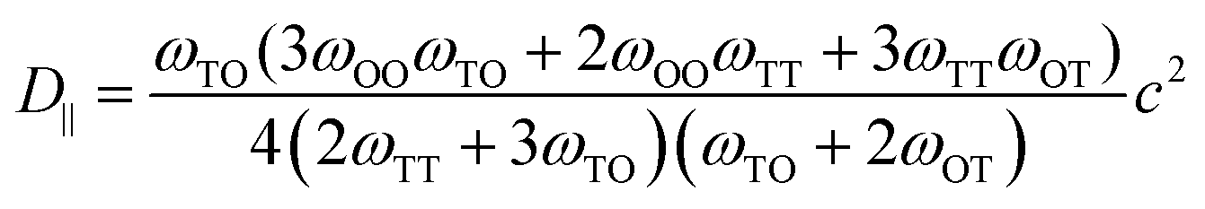 | (6) |
 is the jump rate from one site to another, derived from vij, the effective frequency;26Eb, the energy barrier; kB, the Boltzmann constant; and T, the temperature. A linear fit of the diffusion coefficient curves against temperature gives the diffusion coefficient prefactors (D0⊥ and D0‖) and activation energies (Q⊥ and Q‖) according to the Arrhenius plot of eqn (4).
3 Results
Hydrogen on the surface
Exposure of ruthenium to hydrogen will result in adsorption of hydrogen on the metal, and our study starts with a consideration of adsorption. We choose to study the 0001 surface of ruthenium for two related reasons: first, this plane has the lowest surface energy, and will therefore dominate the exposed surface of a thin film; second, this surface is widely studied and represented in the literature, which allows a measure of validation of the computed energies and geometries.The Ru(0001) surface offers a number of adsorption sites. Two of these sites, labelled fcc and hcp sites, allow three-fold coordination of H with surface Ru atoms, and have the most negative adsorption energies (see Fig. 1). Indeed, all sites show negative adsorption energies, with the top site least favourable. The values remain negative at 100% coverage, i.e. up to 1 H atom per surface Ru atom, with all fcc sites occupied. Previously-published first-principles calculations27,28 show a similar trend in energies of adsorption, with the slight variations in absolute values explained by differences in parameters and software used for the DFT calculations. We thus confirm that hydrogen adsorption on the ruthenium surface is favourable, and that exposing ruthenium to hydrogen will result in saturation of the surface by dissociated hydrogen atoms.
 | ||
| Fig. 1 Adsorption sites for H on the Ru(0001) surface, with corresponding energies of adsorption. | ||
Hydrogen in the bulk
Hydrogen in ruthenium is found as discrete atoms located in the interstices of the hexagonal close-packed lattice. An interstitial atom can occupy one of two sites, octahedral or tetrahedral, relative to the surrounding nearest neighbour metal atoms.In the close-packed lattice, the octahedral sites, which are formed by 6 atoms at the vertices, are larger than the tetrahedral voids, formed by 4. The calculated formation energy of the interstitial hydride, shown at 154 concentration (H/Ru) in Fig. 2, indicates that the octahedral site is preferable. Its 0.34 eV formation energy is much lower than the 0.84 eV of the tetrahedral site. For the subsurface octahedral site which we focus on subsequently, the energy value is nearly the same, 0.30 eV at 128 concentration; this is calculated for a slab, as opposed to the preceding bulk values. Nonetheless, we can conclude that the subsurface state is very similar to the bulk interstitial state.
 | ||
| Fig. 2 Interstitial sites and the corresponding hydride formation energies at hydrogen concentration (H/Ru) equal to 154. | ||
In general, the endothermic nature of interstitial hydride formation makes it unfavourable, and the concentration of the interstitial hydrogen will remain low. An estimate of the fractional concentration of dissolved H atoms in ruthenium is 10−9 relative to the gas, at 1 bar and room temperature; this is according to a lattice gas model with all H atoms in the lower-energy octahedral sites. The low solubility is confirmed by experimental data11 and other computational studies.28
The elementary hops for hydrogen diffusion in the Ru lattice, as well as their effective frequencies and energy barriers are shown in Fig. 3. We obtain for the diffusion prefactors the values D0⊥ = 1.44 × 10⁻⁶ m2 s−1 and D0‖ = 1.70 × 10⁻⁷ m2 s−1. The corresponding activation energies are Q⊥ = 0.80 eV and Q‖ = 0.69 eV. Experimental values for hydrogen diffusion in ruthenium are lacking in the literature. However, our results are of comparable magnitude to those reported in ab initio studies for H diffusion in α-titanium.29
 | ||
| Fig. 3 Jump paths, ZPE-corrected energy barriers, and effective frequencies for H in Ru. The blue spheres show the interstitial sites and the red spheres show transition states between the sites. | ||
Hydrogen diffusion in the near-surface region
A hydrogen atom in the first subsurface layer may diffuse in a number of directions, indicated by the arrows and labels in Fig. 4: (1) within the subsurface layer, to an adjacent octahedral site (sideways); (2) to a deeper octahedral site (downwards); (3) to the surface (upwards). While the presence of hydrogen or tin (hydrides) on the metal surface may alter the energies, barriers, and precise mechanics of the jumps, the picture remains essentially unchanged with respect to the possible migration paths. It should be noted that the tetrahedral sites may also be occupied by the interstitial atoms. However, due to the high energy of formation compared to the more stable octahedral sites, we have chosen to neglect the effect of tetrahedral site occupancy on the processes discussed. | ||
| Fig. 4 Diffusion paths for H atom in first Ru subsurface interstitial site. The sideways arrow shows one of six (6) possible diffusion paths within the same subsurface layer. | ||
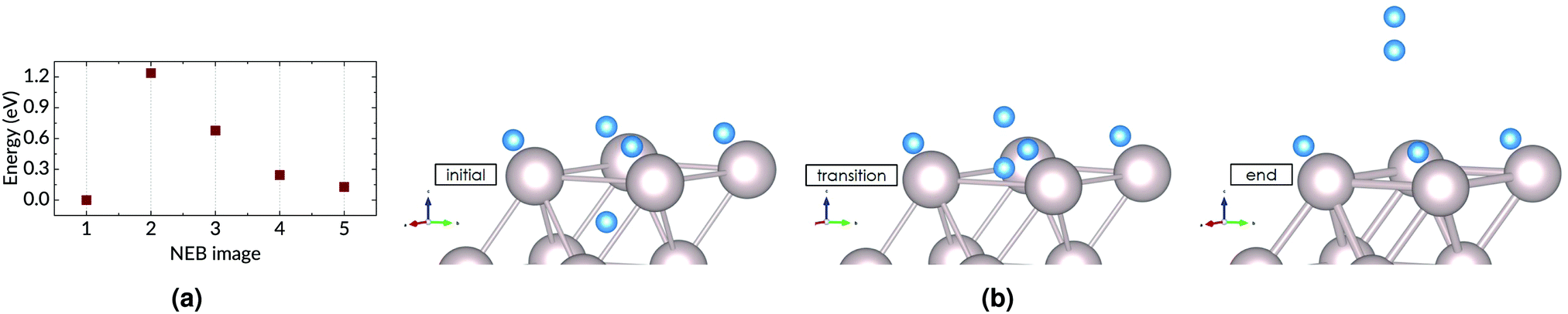
We distinguish three main example surface/subsurface scenarios, and model the hydrogen atom jumps. As illustrated in Fig. 5, these configurations are: (a) with the surface clear of hydrogen; (b) with adsorbed hydrogen; (c) and with adsorbed hydrogen and tin. For each case, the diffusion paths for the hydrogen atom in the subsurface are calculated using the Climbing Image Nudged Elastic Band (CINEB) algorithm. The results are presented in detail below, and summarised in Table 1.
 | ||
| Fig. 5 H in subsurface interstitial sites under a (a) clean Ru surface; (b) Ru surface with H adsorbed; and (c) Ru surface with Sn and H adsorbed. | ||
| Energy barrier (ΔE) [eV] | |||
|---|---|---|---|
| Clean surface | H adsorbed | H & Sn adsorbed | |
| Sideways | 0.73 (+0.00) | 0.78 (+0.00) | 0.95 (+0.12) |
| Downwards | 0.78 (+0.02) | 0.48 (−0.17) | 0.56 (+0.06) |
| Upwards | 0.17 (−0.93) | — | — |
| Upwards (AD) | — | 1.20 (+0.13) | 1.89 (+0.03) |
 | ||
| Fig. 6 Diffusion paths for H atom in subsurface under a clean ruthenium surface. The results of 5-image NEB calculations, as well as initial, transition, and end states are shown for: (a) sideways diffusion within the layer; (b) downwards into a deeper layer; and (c) upwards to the surface. | ||
 | ||
| Fig. 7 Multi-step diffusion from subsurface to surface. (a) Surface sites are all occupied, (b) adjacent site is vacated and adatom can move to it, (c) surface site is free and atom in interstitial site can move to the surface. | ||
 | ||
| Fig. 8 (a) The result of a 5-image NEB calculation; and (b) the initial, transition, and end states for associative desorption of hydrogen from subsurface octahedral and surface fcc sites, with 1 H atom adsorbed per surface Ru atom. | ||
4 Discussion
We have put forward a model of the diffusion of an H atom in the Ru lattice, focusing on the paths available to an atom in the near-surface region. Each of the diffusion steps presented in the preceding section faces its own peculiar combination of barriers and probabilities.The sideways jump faces different barriers for the clear and occupied states of the surface, though the 0.05 eV difference is quite slight. In other words, the conditions for the atom diffusing within the layer are essentially unchanged by the presence of hydrogen on the surface. However, when Sn is present, this sideways diffusion changes: the barrier and ΔE are higher. This is explained by the proximity of the Sn atom, as the change in energy is a result of the change in position relative to the Sn atom and its immediate neighbours.
Moving deeper into the bulk is a relatively simple one-step process, from one octahedral site to another, over a barrier of 0.48–0.78 eV. There is only one destination site, directly below the initial site. If this site happens to be occupied, this migration becomes impossible. This site is unlikely to be occupied, however, owing to the +0.34 eV formation energy and the consequent low solubility of H in Ru. It is notable that this downwards hop results in a lowering of energy (−0.17 eV) relative to the subsurface site when the surface is covered with hydrogen, tilting the situation in favour of deeper migration.
The interstitial atom can also move to the fcc site on the surface, over a barrier that is only 0.17 eV when the surface is clear of adsorbates. This is a much lower barrier than the others faced by the diffusing atom, much more likely to be scaled. Moreover, due to the lower total energy of the adsorbed state, this is an exothermic process, with the end state 0.93 eV lower in energy than the starting point in the interstitial site. However, this escape is contingent on the fcc site being unoccupied. In the case of an occupied surface site, the subsurface-to-surface transition becomes a multi-step process which must involve the vacation of a surface site for the H atom, due to diffusion or recombination. When there is a steady supply of H atoms and molecules to the surface (as is the case when the multi-layer mirror is exposed to H plasma), the interstitial H atom is also in competition for surface sites with this H supply. Each of these conditions reduces the probability of escape, and increases the likelihood of deeper penetration.
A similar site-blocking effect has been proposed to explain the retarded dissociation of YH3 under a Ru film.17 Soroka et al. observed that the unavailability of surface sites prevented the escape of hydrogen. By raising the temperature of the sample above the desorption temperature, the hydrogen atoms released from the YH3 layer were able to diffuse to the surface much more rapidly, allowing the decomposition of the yttrium trihydride to proceed. In this instance, only hydrogen adatoms were present. In other studies, the presence of other species, such as carbon or chemically active gases, will reinforce the blocking effect not just by occupying the surface but also by impeding the recombination and desorption of hydrogen.15
In the case of a ruthenium thin film exposed to plasma containing a large fraction of atomic hydrogen, the availability of surface sites is limited. Hydrogen readily adsorbs on the ruthenium surface. This means that any hydrogen which ends up within the ruthenium faces an obstacle to escape. The “injection” of hydrogen into the subsurface is caused by the presence of tin, which lowers the penetration barrier.13 The diffusion coefficients we have calculated indicate that hydrogen diffusion within the ruthenium proceeds at a rate similar to that of hydrogen in other metals, and poses no great obstacle. Tin on the surface also affects surface diffusion of hydrogen, i.e. it may reduce the rate at which sites are freed.13 Thus the likelihood of diffusion to the interface and subsequent blistering is greatly increased when the concentration of hydrogen in the subsurface is significantly raised. In this way, the surface site blocking effect of hydrogen and tin plays a key role in the blistering of the ruthenium film. To be perfectly accurate in answering our initial question: the hydrogen which enters the ruthenium thin film does eventually leave; it simply ends up in the blisters at the opposite face.
5 Conclusion
In this article we have presented the case for the influence of surface saturation on hydrogen diffusion to the interface between a ruthenium thin film and its substrate, via an examination of the diffusion paths available to a hydrogen atom in the interstitial site just beneath a Ru(0001) surface. By performing transition state calculations of the key hydrogen migrations, we have shown a clear effect of surface occupancy on the energy barriers to diffusion of a hydrogen atom in the near-surface interstices. Our results indicate that the blocking of access to the surface results in increased likelihood of diffusion deeper into the metal lattice. In conjunction with the reduced energy barrier to subsurface penetration in the presence of tin, this effect leads to accumulation of hydrogen in the metal and interface, and subsequent blistering of the ruthenium thin film. This indicates that modifying and controlling the surface coverage may be an effective method of controlling the amount of hydrogen retained in the metal and underlying layers.Author contributions statement
S. T. and T. M. conceived the study, C. O. performed the calculations. All authors analysed the results and reviewed the manuscript.Conflicts of interest
There are no conflicts of interest to declare.Acknowledgements
This research was carried out under project number T16010a in the framework of the Partnership Program of the Materials innovation institute M2i (http://www.m2i.nl) and the Technology Foundation TTW (http://www.stw.nl), which is part of the Netherlands Organization for Scientific Research (http://www.nwo.nl).References
-
C. Bruneau and P. H. Dixneuf, Ruthenium in Catalysis, Springer International Publishing, 2014, vol. 48 Search PubMed
.
- A. G. Knapton, Platinum Met. Rev., 1977, 21, 44–50 CAS
- N. A. Al-Mufachi, N. V. Rees and R. Steinberger-Wilkens, Renewable Sustainable Energy Rev., 2015, 47, 540–551 CrossRef CAS
- B. Sakintuna, F. Lamari-Darkrim and M. Hirscher, Int. J. Hydrogen Energy, 2007, 32, 1121–1140 CrossRef CAS
- T. Hübert, L. Boon-Brett, G. Black and U. Banach, Sens. Actuators, B, 2011, 157, 329–352 CrossRef
- Y. Ueda, J. Coenen, G. De Temmerman, R. Doerner, J. Linke, V. Philipps and E. Tsitrone, Fusion Eng. Des., 2014, 89, 901–906 CrossRef CAS
- Y. B. He, A. Goriachko, C. Korte, A. Farkas, G. Mellau, P. Dudin, L. Gregoratti, A. Barinov, M. Kiskinova, A. Stierle, N. Kasper, S. Bajt and H. Over, J. Phys. Chem. C, 2007, 111, 10988–10992 CrossRef CAS
- S. Bajt, H. N. Chapman, N. Nguyen, J. B. Alameda, J. C. Robinson, M. E. Malinowski, E. Gullikson, A. Aquila, C. Tarrio and S. Grantham, Proc. SPIE, 2003, 5037, 236–248 CrossRef CAS
- A. S. Kuznetsov, R. W. E. van de Kruijs, M. A. Gleeson, K. Schmid and F. Bijkerk, J. Surf. Invest.: X-Ray, Synchrotron Neutron Tech., 2010, 4, 563–566 CrossRef
- A. S. Kuznetsov, M. A. Gleeson and F. Bijkerk, J. Appl. Phys., 2014, 115, 173510 CrossRef
- R. B. McLellan and W. A. Oates, Acta Metall., 1973, 21, 181–185 CrossRef CAS
- P. Feulner and D. Menzel, Surf. Sci., 1985, 154, 465–488 CrossRef CAS
- C. Onwudinanti, I. Tranca, T. Morgan and S. Tao, Nanomaterials, 2019, 9, 1–18 CrossRef PubMed
- A. I. Livshits, M. E. Notkin and A. A. Samartsev, J. Nucl. Mater., 1990, 170, 79–94 CrossRef CAS
- Y. Ueda, T. Shimada and M. Nishikawa, Nucl. Fusion, 2004, 44, 62–67 CrossRef CAS
- S. Ogura, M. Okada and K. Fukutani, J. Phys. Chem. C, 2013, 117, 9366–9371 CrossRef CAS
- O. Soroka, J. M. Sturm, R. W. van de Kruijs, C. J. Lee and F. Bijkerk, Appl. Surf. Sci., 2018, 455, 70–74 CrossRef CAS
- G. Kresse and J. Hafner, Phys. Rev. B: Condens. Matter Mater. Phys., 1994, 49, 14251–14269 CrossRef CAS PubMed
- G. Kresse and J. Furthmüller, Comput. Mater. Sci., 1996, 6, 15–50 CrossRef CAS
- D. Joubert, Phys. Rev. B: Condens. Matter Mater. Phys., 1999, 59, 1758–1775 CrossRef
- J. D. Perdew, K. Burke and M. Ernzerhof, Phys. Rev. Lett., 1996, 77, 3865–3868 CrossRef CAS PubMed
- G. Henkelman, B. P. Uberuaga and H. Jónsson, J. Chem. Phys., 2000, 113, 9901–9904 CrossRef CAS
-
H. King, CRC Handbook of Chemistry and Physics, CRC Press, 2012, pp. 15–18 Search PubMed
- K. K. Irikura, J. Phys. Chem. Ref. Data, 2007, 36, 389–397 CrossRef CAS
- S. Ishioka and M. Koiwa, Philos. Mag. A, 1985, 52, 267–277 CrossRef CAS
- G. H. Vineyard, J. Phys. Chem. Solids, 1957, 3, 121–127 CrossRef CAS
- I. M. Ciobica, A. W. Kleyn and R. A. Van Santen, J. Phys. Chem. B, 2003, 107, 164–172 CrossRef CAS
- I. Del Rosal, L. Truflandier, R. Poteau and I. C. Gerber, J. Phys. Chem. C, 2011, 115, 2169–2178 CrossRef CAS
- Y. Lu and P. Zhang, J. Appl. Phys., 2013, 113, 193502 CrossRef
| This journal is © the Owner Societies 2020 |