 Open Access Article
Creative Commons Attribution 3.0 Unported Licence
Charge separation and successive reconfigurations of electronic and protonic states in a water-splitting catalytic cycle with the Mn4CaO5 cluster. On the mechanism of water splitting in PSII†
Kentaro
Yamamoto
 and
Kazuo
Takatsuka
 *
*
Fukui Institute for Fundamental Chemistry, Kyoto University, Sakyou-ku, Kyoto 606-8103, Japan. E-mail: kyamamoto@fukui.kyoto-u.ac.jp; kaztak@fukui.kyoto-u.ac.jp
First published on 30th March 2020
Abstract
Much insight into the basic mechanisms of photoexcited and collision-induced ground-state water splitting has been accumulated in our nonadiabatic electron wavepacket dynamics studies based on a building-block approach reaching up to systems of binuclear Mn oxo complexes. We here extend the study to a ground-state water-splitting catalytic cycle with tetranuclear Mn oxo complex Mn4CaO5, or Mn3Ca(H2O)2(OH)4–OH–Mn(4)(H2O)2, where Mn3Ca(H2O)2(OH)4 is fixed to a skewed cubic structure by μ-hydroxo bridges and is tied to the terminal group Mn(4)(H2O)2. We show using the method of real-time nonadiabatic electron wavepacket dynamics that four charge separation steps always take place only through the terminal group Mn(4)(H2O)2 alone, thereby producing 4 electrons and 4 protons which are transported to the acceptors. Each of the three charge separation steps is followed by a reloading process from the skewed cubic structure, by which electrons and protons are refilled to the vacant terminal group so that the next charge separation dynamics can resume. After the fourth charge separation an oxygen molecule is generated. It is emphasized that the mechanisms of O2 generation should depend on the multiple channels of reloading.
1 Introduction
Photoinduced water-splitting| 2H2O + 4hν → 4H+ + 4e− + O2 | (1) |
A major difference between biological and artificial water-splitting systems is that the catalytic reaction of the former is widely believed to take place in the electronic ground state of Mn4CaO5, while the catalysts used in the latter are usually directly photoexcited. The main characteristics of these types of splitting are summarized in Table 1, which shows the essential differences between the mechanisms.
It is quite natural to conceive that the water-splitting cycle is triggered and driven by four charge separation dynamics. Besides, it is known that even a mononuclear Mn oxo complex can induce charge separation by itself. However, it alone does not constitute a catalytic cycle. Therefore we have been scrutinizing the dynamics of charge separation by increasing the number of Mn atoms in the oxide complex and/or proton–electron acceptors step by step in order to identify what chemical processes are essential and to see what follows the charge separation dynamics, which should eventually lead to oxygen generation before completing the catalytic cycle. Such a building-block approach, or bottom-up approach, by means of a nonadiabatic electron wavepacket study has recently reached a photo-catalytic cycle with binuclear Mn oxo complexes.17–22 We here extend the study to a ground-state water-splitting catalytic cycle in terms of a tetranuclear Mn oxo complex.
We here summarize observations attained up to the binuclear Mn oxo complexes, which are relevant to the present study on Mn4CaO5.
(I) On charge separation (CS) dynamics, which should take place four times by four photon absorption to complete the circuit of a catalytic cycle: at each incident of CS, a proton and an electron are simultaneously lost from the moiety surrounding the possible catalyst, thereby keeping electric neutrality. The characteristics of CS dynamics to be noted are:
(I-A) CS dynamics generally passes across nonadiabatic regions (usually through conical intersections), inevitably accompanied by a nonadiabatic transition of adiabatic electronic states. The very basic mechanism of a single CS event is due to what we call coupled proton electron-wavepacket transfer (CPEWT), which is one of the so-called proton-coupled electron transfer (PCET) mechanisms.23,24 In CPEWT, electron wavepackets and protons individually take different pathways (unlike hydrogen atomic migration) and arrive at different destinations in a single or multiple molecules, and thereby CS is realized in the acceptors.17,18
(I-B) Acceptors of electrons and protons for CPEWT can be different from each other and may be spatially separated so that electrons and protons are relay-transferred eventually to their final destinations. The Rydberg states of nitrogen atoms in amino acids, which usually form a highly quasidegenerate manifold of electronic states and spread broadly in space, often serve as a very good acceptor of transferred electrons.19
(I-C) CS due to CPEWT can take place not only in photoexcited states but even in ground electronic states. Ground-state charge separation is induced by collision (contact) with external molecules of positive charge. The quantum mechanism is similar to those of chemiluminescence or bioluminescence, and hence we refer to it as chemi-charge-separation.20 CS in PSII is widely believed to take place in the electronic ground state, and this is yet hard to accept from the viewpoint of quantum dynamics. But this kind of dynamics has been clarified and justified by our study.20
(I-D) The Ca atom sitting close to the electron donating Mn has been found to dramatically prevent charge recombination between produced protons and electrons in CS.18
(II) Other elementary processes that are needed to materialize water-splitting catalytic cycles:
(II-A) Buffering of electrons and protons is necessary. For a catalytic cycle to be completed, electrons and protons that are lost (handed) to acceptors by CS dynamics should be recovered to their original positions. Hence electrons and protons to be supplied should be temporarily stored (or buffered) somewhere. For a mononuclear Mn oxo complex, molecules of such buffering functions are needed in addition to the oxo complex. Therefore the mono Mn oxo complex alone cannot work as a catalyst, even though it can perform CS. For a binuclear Mn oxo complex, it turns out that such external buffering molecules are not needed, since a part of the complex itself can work as a buffer.21,22
(II-B) Reloading (RL) of electrons and protons to the molecular center of CS is inevitable to resume the next CS dynamics.22
(II-C) Mn reduction (MR) is also needed. Due to the CS and/or RL processes, Mn atoms can become charge positive, and those positively charged Mn atoms should be neutralized (reduced) in order to continue the catalytic cycle.22
(II-D) Formation of O–O bonds: O–O bonds and/or O![[double bond, length as m-dash]](https://www.rsc.org/images/entities/char_e001.gif) O in the triplet state are to be formed.21,22
O in the triplet state are to be formed.21,22
(II-E) Proton relay transfer along hydrogen-bonding water molecules is necessary.
(II-F) Radical chain transfer along hydrogen-bonding water molecules is also utilized.21,22
In terms of the above electron dynamics studies, we have thus found that a binuclear Mn oxo complex can serve as a catalyst for a four-photon photoexcited water-splitting cycle.
Here in this paper we construct a catalytic cycle in which a tetranuclear Mn oxo complex in the electronic ground state works as a catalyst without intermediate emergence of peroxides. The Mn complex we study is Mn4CaO5,3 which is tied to acceptors of electrons and protons through hydrogen-bonded water molecules. Mn4CaO5 is schematically represented as Mn(4)–O-Cub, where Cub indicates a skewed cubic structure composed of Mn3CaO4. We here set the following working hypotheses: (1) the mutual spatial orientation between the cluster and its adjacent acceptors of electrons and protons is basically maintained throughout the entire catalytic cycle, assuming that Mn4CaO5 does not rotate with respect to the surrounding molecular frame. We further assume that the terminal Mn (denoted as Mn(4)) is solely responsible for all the four collision induced charge separations. (2) The skewed cubic part serves as a buffer of electrons and protons, and reloads three electrons and three protons that are lost in the first three CS dynamics. (3) After the final (fourth) CS dynamics is over, four protons and four electrons are extracted from water molecules leaving one oxygen molecule behind, and Mn4CaO5 is retrieved in the end.
The main aim of this paper is to examine whether the above hypotheses indeed work. Besides, attention is paid to the mechanism of reloading of protons and electrons to the appropriate places in the moiety of Mn(4), which should make it possible for the next CS from Mn(4) to resume. We also examine the role of Mn reduction processes to possibly generate an oxygen molecule and thereby complete one circuit of the catalytic cycle. To examine the entire scenario, we apply the method of nonadiabatic electron wavepacket dynamics and ab initio methodology for energetics.
This paper first presents a series of model chemical schemes of an entire catalytic cycle in Section 2. Then the dynamics and energetics relevant to the water splitting are tracked numerically in Section 3. This paper concludes with Section 4 with some remarks.
2 Schematic representation of a catalytic cycle for water splitting by a tetranuclear Mn oxo complex
2.1 Molecular composition
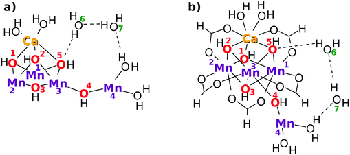
As a result, the Mn4CaO5 cluster has a rather large open space, which is roughly surrounded by Mn(4), O(4), Mn(3), O(2), O(5), and Ca. We refer to this open-space as the reaction field for water splitting. Indeed one can see such an open space in the crystal structure of Mn4CaO5 in Fig. 2 of ref. 2. This open space can be used also for in-and-out motion of molecules such as external water molecules and oxygen molecules. We place two water molecules marked with O(6) and O(7) in the reaction field as depicted in Fig. 2. These molecules can serve as a hydrogen-bonding network to relay-transport protons by connecting the skewed cubic Mn3Ca oxo complex and Mn(4)(H2O)2. Also, these water molecules are involved in the reloading of protons as a part of an H-bond network and are supposed to play a role in oxygen generation. Other important chemical dynamics can take place in this space. By contrast, the other sides of the cubic structure of Mn3Ca(H2O)2 are shielded by the carboxy groups, and it is rather hard to approach Mn(1), Mn(2), O(1) and O(2).
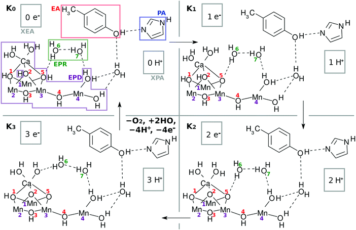 | ||
| Fig. 2 Chemical scheme of the K-state cycle of water-splitting catalyzed by the Mn4Ca oxo complex. See the text for the labeling scheme. Note that the five carboxy groups bridging either Mn–Mn or Mn–Ca in EPD are not shown here. See Fig. 1b to find the full expression. The H of H3 in H3–EPD–H is on either O(2), O(5), or Ca–OH, while H on the right hand side of H3–EPD–H lies on Mn(4)–OH. Note that H on O(2) is not a member of the definition of EPD in K0. | ||
The present work assumes that all the bridging oxygen atoms in the skewed cubic structure Mn3CaO4 of the S0 state in the Kok cycle (here K0 of Fig. 2), the bridge being termed as a μ-oxo bridge, are all hydroxylated as –OH–. Among the others, however, only two hydroxyl groups, O(2)H and O(5)H, are essential for the present water-splitting dynamics, since only these two groups face the reaction field.
It does not seem easy for X-ray related experiments to determine whether the μ-oxo bridge is hydroxylated, since the hydrogen atoms in this circumstance are too small.3,6 However, it is natural to presuppose the presence of hydroxy groups under the circumstance where the Cl− ions exist nearby the cluster.2 In fact, Landman et al.9,25 have experimentally discussed the presence of a μ-hydroxo bridge even in gas phase Mn oxo clusters such as CanMn4−nO4+. Mafune and his group have also identified the presence of a μ-hydroxo bridge in the Mn4CaO5 cluster with vibrational spectroscopy, the hydroxy groups having been formed by collision of the naked Mn4CaO5 with water molecules in the gas phase.26 Furthermore, Lohmiller et al. have explicitly evidenced the presence of a μ-hydroxo bridge at least for O(5) in Mn4CaO5 taken from native PSII.27 In our proposed model, the relative positions of O(2) and O(5) are mutually symmetric, and hence we also assume the bridge of O(2) to be hydroxylated. Later, those protons on O(2) and O(5) will be shown to originate from water molecules that are split in the catalytic cycle. We assume that O(1), O(3) and O(4) are also hydroxylated, but these protons will turn out not to be directly involved in water oxidation.
The Mn4Ca oxo complex serves as an electron–proton donor (EPD), the formal oxidation state of which is represented as H3–EPD–H. Here H3 on the left side are located on the cubic structure Mn3CaO4, whereas H on the right side is one of H atoms in the water molecule coordinated to Mn(4), see panel K0 in Fig. 2. Note that the three hydrogens on the left-hand-side of H3–EPD–H are located at O(2) and O(5) and in one of the H2O on the Ca atom.
The 3 + 1 structure, that is, the oxo complex composed of Mn3Ca and the terminal Mn(4), naturally suggests a hypothesis that only Mn(4) is responsible for the charge separation. The molecular orbital (MO) of Mn(4) from which an electron is abstracted should be high enough in energy and diffuse enough in space to access an electron acceptor. This feature is brought about by keeping Mn(4) coordinated by less anionic ligands. This is the “1” part of the 3 + 1 structure. On the other hand, water oxidation needs low energy and vacant MOs to abstract an electron from a water molecule in the end. This feature is realized by placing many anionic ligands on Mn atoms in the “3” part of the 3 + 1 structure. The view of the 3 + 1 structure, Mn3CaO4(H2O)2 as the “3” part and MnO(H2O)2 as the “1” part, is in harmony with the widely accepted structure of the natural oxygen-evolving complex in PSII.1–3,6–8
• an electron–proton donor (H3–EPD–H): oxygen-evolving complex (OEC) including the Mn4CaO5 cluster
• an electron acceptor (EA–H = 4-methylphenol): D1-Y161 or TyrZ (YZ)
• a proton acceptor (PA–H = imidazole): D1-H190 or HisZ
• electron–proton resources and a bridging water molecule between EPD and EA (EPR = 2H2O): water cluster between OEC and TyrZ
• an external electron acceptor (XEA): P680
• an external proton acceptor (XPA): lumenal bulk phase
Here again H3–EPD–H = Mn4Ca(OH)5(H2O)4(HCOO)5 (see Fig. 1).
The pair of electron acceptor EA and proton acceptor H–PA is a Y-shaped acceptor consisting of intramolecularly polarized 4-aminophenol and imidazole.19 The electron and the proton thus drawn apart on this Y-shaped acceptor are assumed to be further transported through their own pathways to XEA and XPA, respectively.
The external electron acceptor XEA finally accepts those isolated electrons. The external proton acceptor XPA has the same role for protons. In the present study, the functions of XEA and XPA are not defined explicitly,21 and they will be implicitly addressed only in the study of energetics.
2.2 Overview of the catalytic cycle proposed
Fig. 3 and its caption show an example of the mechanism of chemi-charge-separation in the case of the mononuclear Mn oxo complex: (1) an outer molecule denoted as EA0, which has been oxidized somewhere else originally due to photoabsorption, approaches to make contact with EA, which induces CPEWT from EA – synchronous transfer of an electron wavepacket to EA0 and of a proton to PA. After EA0 captures the electron, it leaves the stage and the coherent overlap between the two electronic states of EA0 and EA is switched off, shutting off the channel of time-reversal of the reaction. (2) Then another ground-state nonadiabatic dynamics follows, where an electron wavepacket jumps from EPD (a Mn oxide) to EA, along with the return (thus making a reciprocal motion) of a proton from PA to EA.31 (3) Then proton relay-transfer occurs from EPD to PA, leaving electronic polarization in EPD. (4) PA captures a proton, while EA0 adopts an electron, and thereby charge separation is completed. It turned out incidentally that the reciprocal motion of a proton between EA and PA plays a crucial role to maintain the electric neutrality of EPD and EA and furthermore this type of motion is physically relevant to one-way (non-reversible) transfer of electrons.31
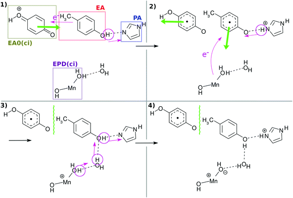 | ||
| Fig. 3 Schematic illustration of the mechanism of collision-induced (ci) charge separation catalyzed by the mononuclear Mn oxo complex.20 All the charge separations in the present tetranuclear system proceed in qualitatively the same manner as this scheme. The green thick arrow denotes the translation of the molecules to approach or to recede. EA0(ci) and EPD(ci) denote the primary electron acceptor and electron–proton donor for the collision-induced mechanism, which correspond to XEA and EPD in the present mechanism, respectively. The wavy line between EA0(ci) and EA indicates that there is a long distance between them for quantum coherence to be broken. | ||
In what follows, our dynamical calculations presented in Fig. 2 begin with stage (2) of Fig. 3 after the electron transfer due to the contact of EA0 and EA has been successfully finished.
Under this situation, it is quite natural to assume that Mn(4) alone must be responsible for all the four charge-separation dynamics, that is, electrons and protons should be provided to EA and PA, respectively, only through the close surroundings of Mn(4). Indeed, we will show that this can be the case if the electronic and protonic states of this area can be well restored on each occasion of charge separation. Such recovery will be assisted by reloading of electrons and protons from the site of the skewed cubic structure Mn3CaO4(H2O)2 and eventually from external water molecules such as those in EPR of Fig. 2.
The structures of all the Knm states schematically represented in the figures have been actually confirmed to be sitting in their local minima of the ground-state potential energy surfaces. Hence the molecular states appearing here are realistic in this sense.
The K-state representation is analogous to the Kok cycle of PSII.7 A major dissimilarity is that the K-cycle has only 4 nodes, rather than 5 in the Kok cycle, since we treat the S4 state as an intermediate state appearing between the K3 and K0 state.
The present model catalytic cycle has been designed under the understanding that the stable and robust charge separation dynamics is the most vital process for water splitting in nature. Then the other chemical machineries, such as reloading of electrons and protons and the reduction of Mn(4), will rather automatically follow to assist the completion of the four step charge separation.
2.3 Working catalytic system in the precise scheme of the K-state cycle
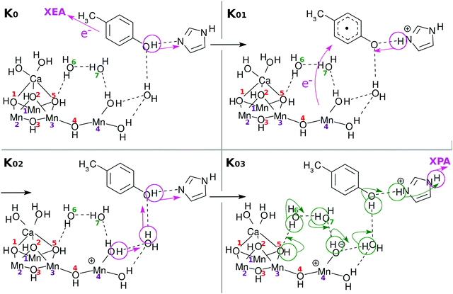
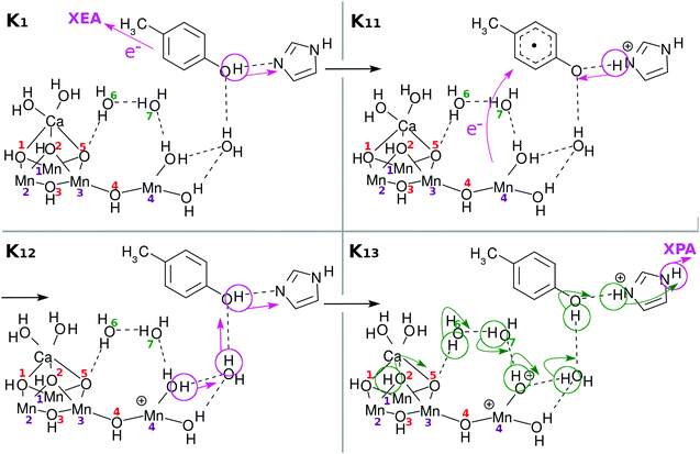
We next describe how the transitions in K-states work. Note beforehand that the elementary subprocesses Knm are consecutive members of Kn, although we describe each below as though it represents a single event. For example, some reactions involving proton relay-transfer (e.g., K0 → K01 and K04 → K05) are regarded as a single process, even if local minima exist along the reaction paths.In transitions from the K0 state to K1, K1 to K2, and K2 to K3, the processes include only charge separation (CS) and reloading (RL). Only in the last transition from K3 to K0 do we discuss, besides CS, the final reduction of the Mn(4) atom, water molecule decomposition, and associated O2 formation. The details of the individual subprocesses are described in the figure captions so that the events can be tracked only by watching the figures.
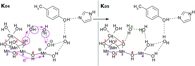
As a result of donation of an electron and a proton, Mn(4) and the OH site next to it become electronically polarized. For the next charge separation dynamics to resume, the vacancy in the 4s-like diffuse orbital on Mn(4)+ needs to be refilled, and also a proton should be reloaded to the right position.
Fig. 5 suggests one of such possible reloading processes: the panel for the state K04 suggests that an electron transfers from the skewed cubic structure to Mn(4)+, while a proton is relay-transported from O(5). The electric neutrality is thus maintained, although the radical property can be significantly changed.
Incidentally we note that the transition from K0 to K05, which is essentially equal to K1, can take place in dark conditions, as long as some EA0 molecules happen to remain in the molecular system. The possible collision of such active EA0 with EA will bring the K0 state to K1, the reverse reaction of which cannot happen, whereas the K1 state cannot proceed to K2 because of the lack of active EA0 in the dark place. In this regard it has been found that S1 is automatically produced from S0 due to oxidation by D2-Tyr160 even in dark conditions.7
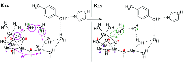
Here again the reloading process is needed for the next charge separation dynamics to materialize. There can be multiple ways of reloading, and we show only one of the likely channels in Fig. 7. Once again an electron is transferred from the skewed cubic structure and a proton is abstracted from the site of O(2)H. The positions of O(2)H and O(5)H are mutually symmetric and there is no reason to distinguish them at this stage.
Incidentally, it is demonstrated in the Kok cycle that only an electron is released in the transition from S1 to S2.6,7 This does not seem to be consistent with our model of the transition from K1 to K2, in which both an electron and a proton are handed over to the acceptors due to the charge separation dynamics. However, a direct comparison between experiments and the present theoretical results is not rationalized, since in contrast to our simple theoretical calculations, the experimental observations of protons and electrons are made indirectly through complicated channels of proteins and such.
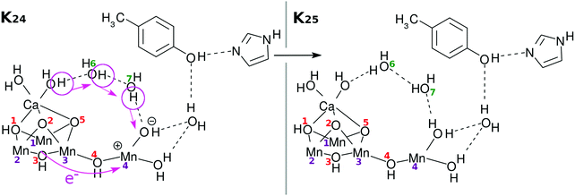
Again an electron is reloaded from the cubic subcluster. However, we see a new feature in the reloading process as shown in Fig. 9. Since O(1)H and O(3)H lie on the opposite side of the reaction field, the protons attached to them are hard to dispatch. Instead it is likely that one of the protons of the water molecules coordinated to Ca atom will be removed and relay-transferred (see K25 in Fig. 9). Thus, finally three electrons and three protons are subtracted from the skewed cubic structure Mn3CaO4(H2O)2.
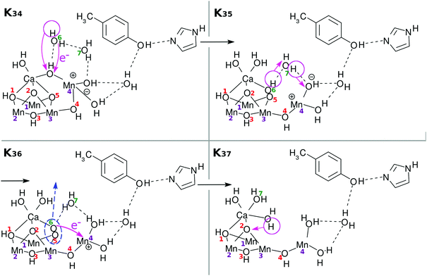
There have been many mechanisms proposed about oxygen generation catalyzed by Mn4CaO5 in PSII, aside from those in the studies of artificial photocatalytic reactions. Siegbahn opened this field of quantum chemistry, to the best of our knowledge, and has been leading since then1,32–34 (see also ref. 8, 35, 36 and references cited therein). We here propose another possible mechanism as illustrated in Fig. 11: first the above Ca–OH reduction is coupled with simultaneous (concerted) formation of an O(5)–O(6) bond (K34 → K35). Then a proton is transferred from O(5)–O(6) to Mn(4)–OH (K35 → K36). Also synchronous electron transfer from O(5)–O(6) leads to the release of molecular oxygen O2. This reaction may also be coupled to K36 → K37. The resultant vacancy produced by the O2 release is filled by the H2O on the Ca atom, and H2O(7) is attached on Ca (K36 → K37). Proton transfer to O(2) from one of the three H2O molecules is coupled with Mn(1)–O, Mn(3), and Ca–O bond formation. To fully reproduce K0, two H2O molecules need to be supplied from the environment (K37 → K0). In this particular mechanism of O2 generation, an oxygen atom (O(5) in this figure or O(2) as well) at one of the μ-hydroxo bridges is exchanged (replaced) with an oxygen of some of the water molecules. Also, one of the water molecules initially attached to Ca atom is likely to be replaced with another H2O after all the cycle is completed. We refer to ref. 4, 5, 36 and 37 for the extensive discussion of the possible replacement of those oxygen atoms. This completes one cycle of the present water splitting.
An important note with respect to Fig. 11 is that we intentionally do not draw the two water molecules to be inserted to bring the stage of K37 back to K0, just for clearer graphical illustration. The series of schemes from K0 to K37 is self-contained in that water splitting is achieved within the molecular system initially prepared in K0 and that two water molecules are added after or during the process up to K37. However, it is obvious that additional water molecules invited from outside should work so as to help the system proceed favorably. For instance the oxygen molecule generation depicted in K36 in Fig. 11 should take place in a concerted manner with the water insertion, which should suppress the energy required to form O2.
Note that the reloading processes are not necessarily unique and may have multiple reaction pathways, the flexibility brought about by which should give robustness to plants in nature. Accordingly, there can exist other mechanisms of O2 generation, depending on the reloading processes realized up to the state K3. For instance, external water molecule(s) can be introduced even at a stage as early as when the subprocess K15 finishes, where two protons have been removed from O(2) and O(5) (not demonstrated graphically). Such insertion of an additional water molecule can give rise to a different mechanism of O2 generation. Likewise, O2 may be given through other multiple paths with different probability weights. It is also likely that different experimental observations may emphasize different mechanisms. We do not get involved in further exploration of new possible mechanisms of O2 generation in this paper.
3 Dynamics and energetics behind the proposed mechanism
The proposed model of the catalytic cycle has been built up not only based on the knowledge learned from the literature but in terms of our own theoretical and computational studies. We here in this section show such theoretical and computational background that has led us to a picture of water splitting.We first note that we could not perform the full dimensional nonadiabatic electron wavepacket dynamics calculations over the entire system, from those of K0 to K3 in Fig. 2. This is simply because the entire system is far larger than our computational capability. The largest obstacle is that we have four Mn atoms that together make exceedingly huge active spaces in which to sufficiently describe the relevant open-shell electronic states. So our strategy is to perform nonadiabatic electron wavepacket dynamics in terms of state-averaged SA-MCSCF type electronic wavefunctions for the four charge separation dynamics through the Mn(4) atom only. Since it is key to the present study to assure that such four-step charge separation through Mn(4) is indeed possible, we need to achieve rather faithful nonadiabatic electron wavepacket calculations to track the real-time CPEWT dynamics. In these calculations, the active spaces relevant to the other Mn atoms (Mn(1) to Mn(3)) are fixed. In addition, we could not help omitting the Ca atom and its attached groups from the skewed cubic structure, namely, Ca(H2O)2 (HCOO)2 again, for the reason of computational limitation.
Then each of the four charge separations is followed by individual reloading dynamics. For the same computational limitation reason as above, we apply a modified unrestricted Hartree–Fock (UHF) method to track nonadiabatic nuclear paths in an analogous manner to the ab initio MD method. With these simplified calculations we reach the conclusion that electrons are certainly transported from the skewed cubic structure of Mn3CaO4(H2O)2 to reload the 4s-like diffuse orbital of Mn(4).
The energy profile of the entire reaction scheme and some other structural calculations as well will be illustrated in terms of ab initio configuration interaction calculations. Note that none of the numerical calculations here is aimed at high accuracy performance but qualitative pictures and notions are the goal of this work.
Incidentally, no solvent effect has been taken into account except for the hydrogen-bonded water clusters. Nor are included the protein fields that are supposed to physically support the catalytic system. In these senses the present work is still far from the level of a simulation study.
3.1 Computational methodology
Below we describe the methodological details mainly for the dynamics computations. (See Section S1 of the ESI† for the details of energetics.65)First, the electron wavepacket Ψelec(r,t;R(t)) is expanded in a set of time-independent wavefunctions {ΦI(r;R)} at each nuclear configuration R as
 | (2) |
 | (3) |
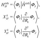 | (4) |
 | (5) |
Among others, the so-called semiclassical Ehrenfest theory (SET) is the simplest approximation, which is also called the mean-field approximation, in which the force matrix of eqn (5) is averaged over the electron wavepacket in such a way that
 | (6) |
 | (7) |
 | (8) |
 | (9) |
The electron flux j(r,t) (also referred to as the Schiff probability current density of electrons50) satisfies
 | (10) |
In the present nonadiabatic electron wavepacket dynamics calculations, the adiabatic electronic wavefunctions attained at each molecular geometry are employed as the basis functions {ΦI} to expand the electron wavepacket Ψelec. These adiabatic states are tracked on-the-fly along the relevant nuclear paths. To do so, the state-averaged multi-configurational self-consistent field (SA-MCSCF)63,64 level of calculations has been employed.
It should be noted that a sudden change of their characters can occur before and after the passage of nonadiabatic regions, which can destruct the time-continuity of Ψelec. To keep the appropriate ordering of the suffix I of ΦI faithfully, we make use of the approximate overlap integrals of the electronic wavefunctions between a time step t and that of one-step before t − Δt.
The level of calculations, spin-multiplicity 2S + 1, and excluded subsystems are summarized in Table 2. The total charge is commonly set to be neutral. 2S + 1 is determined so that the Mn4Ca oxo complex is in a high-spin state in terms of the number of electrons in the Mn 3d orbitals, which is usually the most stable in energy. The number of 3d orbitals required to describe the Mn atoms is estimated by using the conventional formal oxidation states (e.g., Ca2+, O2−, OH−, and HCOO−). The unpaired electron of the phenoxy radical is assumed to have the opposite spin to those of the Mn oxo complex, so that closed-shell phenol is finally formed in the active space. Charge neutralization is assured by summing up the formal charge of typical atoms or molecules excluding Mn, and assuming that oxidation and reduction are compensated only by Mn atoms. The remaining electrons occupying Mn 4s and/or 3d orbitals determine the spin multiplicity. This is a standard way frequently used in the context of inorganic chemistry and works very well to predict or understand reactions. The singly-occupied natural orbitals calculated for a multi-nuclear Mn oxo complex at the SA-MCSCF level occasionally include mixed states of Mn 3d and other orbitals such as O 2p orbitals. Later, we study a relation between the oxidation number and the number of unpaired electrons.
| Subprocess | 2S + 1 | Charge | Level of calculation | Excluded |
|---|---|---|---|---|
| K01 → K02: CS(1) | 20 | +1 | SA(440)-CASSCF(21e,21o) | Ca(HCOO)2(H2O)2 |
| K04 → K05: RL(1) | 21 | 0 | UHF | EA, PA, H2O |
| K11 → K12: CS(2) | 19 | +1 | SA(399)-CASSCF(20e,20o) | Ca(HCOO)2(H2O)2 |
| K14 → K15: RL(2) | 20 | 0 | UHF | EA, PA, H2O |
| K21 → K22: CS(3) | 18 | +1 | SA(360)-CASSCF(19e,19o) | Ca(HCOO)2(H2O)2 |
| K24 → K25: RL(3) | 19 | 0 | UHF | EA, PA, H2O |
| K31 → K32: CS(4) | 17 | +1 | SA(323)-CASSCF(18e,18o) | Ca(HCOO)2(H2O)2 |
3.2 Nonadiabatic electron wavepacket dynamics
It is very difficult to calculate an SET path at the SA-MCSCF level for the reloading mechanisms, because too many CSFs are necessary even for a qualitative description of the mechanism. The critical difficulty lies in the time-evolution of the occupation number of the Mn 3d orbital and/or O 2p orbital of the tetranuclear Mn oxo complex. In the charge separation dynamics, these orbitals are fixed to be inactive (up to doubly-occupied) or virtual (unoccupied) orbitals, and thus the number of CSFs is kept small enough for practical computations yet large enough for a qualitative description of the mechanism.
Taking the first reloading process RL(1) in K04 → K05 as an example, the 3d orbitals of all the four Mn atoms, 2p orbitals of the three μ-hydroxo O atoms, and 4s orbitals of the Mn(4) atom should be included in the active space. However, if the spin multiplicity 2S + 1 is set to be equal to 20 (the high-spin state), the number of CSFs becomes 552![[thin space (1/6-em)]](https://www.rsc.org/images/entities/char_2009.gif) 000, which is a far from practical computation of on-the-fly SA-MCSCF along the paths. We therefore have tested a number of large active spaces within the computationally practical range, but none of them is sufficient for a qualitative description of the mechanism. Therefore we could not avoid abandoning the SA-MCSCF calculations for the electron wavepacket analysis of the mechanism of reloading. Instead, we use the unrestricted Hartree–Fock (UHF) level of calculation to find places for the electronic state of the reactant to undergo a transition to that of the product in the reloading processes. It is also found that these “diabatic” states (see below for the implication of the present diabaticity) have a crossing point like a conical intersection along the path of proton relay-transfer in reloading. When such a crossing appears, our ab initio molecular dynamics is designated to keep tracking on the ground state alone. Accordingly, the conservation of the total energy is violated to a little extent in passing through such “conical intersections”. No remedy to retrieve the conservation has been made in this paper. More about the choice of the initial condition is described in Section S1 of the ESI.†
000, which is a far from practical computation of on-the-fly SA-MCSCF along the paths. We therefore have tested a number of large active spaces within the computationally practical range, but none of them is sufficient for a qualitative description of the mechanism. Therefore we could not avoid abandoning the SA-MCSCF calculations for the electron wavepacket analysis of the mechanism of reloading. Instead, we use the unrestricted Hartree–Fock (UHF) level of calculation to find places for the electronic state of the reactant to undergo a transition to that of the product in the reloading processes. It is also found that these “diabatic” states (see below for the implication of the present diabaticity) have a crossing point like a conical intersection along the path of proton relay-transfer in reloading. When such a crossing appears, our ab initio molecular dynamics is designated to keep tracking on the ground state alone. Accordingly, the conservation of the total energy is violated to a little extent in passing through such “conical intersections”. No remedy to retrieve the conservation has been made in this paper. More about the choice of the initial condition is described in Section S1 of the ESI.†![[thin space (1/6-em)]](https://www.rsc.org/images/entities/char_2009.gif) 65
65
3.3 Charge separation dynamics, energetics of reloading, and oxygen molecule formation
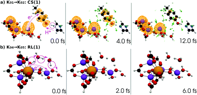 | ||
| Fig. 12 (a) Selected snapshots of the spatial distribution of the unpaired electron density D(r) (yellow contour mesh) and electron flux j(r) along a SET path of K01 → K02: CS(1) (SA-MCSCF level). See Fig. 4 for the corresponding chemical scheme. (b) Selected snapshots of an AIMD path of K04 → K05: RL(1) (UHF level). See Fig. 5 for the corresponding chemical scheme. Note that the time t = 0.0 fs is set to the starting time of the dynamics independently, and there is a somewhat long interval between the two subprocesses (a and b). | ||
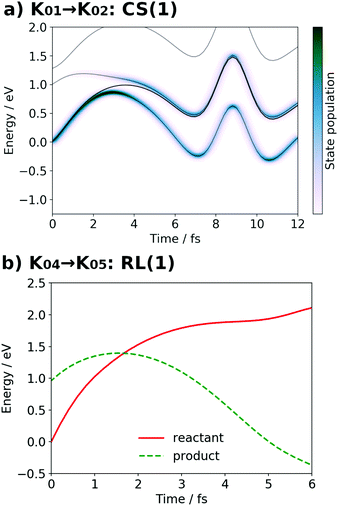
At time t = 0.0 fs, relatively high D(r) is found on EA = 4-methylphenol. This situation corresponds to PSII with  (the TyrZ radical) before the hole transfer to the Mn4CaO5 cluster. As the proton on PA = imidazole is transferred to EA, D(r) on EA gradually decreases as seen in the panels of t = 4.0 fs and t = 12.0 fs of Fig. 12a. This indicates that EA turns into a closed-shell state (i.e., 4-methylphenol) as a result of this collision-induced CPEWT. The electron to be transferred should be assigned to be sitting in the 4s orbital of Mn(4). Indeed D(r) on this orbital decreases prominently as compared to the other orbitals. The electron flux j(r) also supports this view, since the flux is found only around the area near EA and Mn(4). This type of mechanism has already been established in the study on a mononuclear Mn oxo complex.20
It is seen in Fig. 13a that a nonadiabatic transition occurs along the path among the quasi-degenerate adiabatic states. The figure shows the time evolution of potential energy curves VI and state populations |CI|2 along the path. The population of the ground state at t = 12.0 fs is equal to 59% in this CS(1) [K01 → K02]. This implies that the electron wavepacket includes about 40% of the character of the reactant state (character having a radical on EA) even after passing through the nonadiabatic region. If path-branching is invoked, the path assigned to the reactant electronic state would easily induce the backward proton transfer (EA → PA), as we have shown for the excited-state charge separation.18
The natural orbitals of the MCSCF active space for CS(1) in K01 → K02 can be categorized into three types, namely, 3d/2p(Mn4O5), 4s(Mn(4)), and π(EA), in which the expression “(X)” indicates that the orbitals belong to the atom or molecule X. Again, 4s(Mn(4)) indicates the 4s orbital of Mn(4), which is responsible for the charge separation. Here 3d/2p(Mn4O5) denotes the superposition of the 3d(Mn) and 2p(O) orbitals of the Mn4O5 oxo complex.
It makes no sense to attempt to further assign the natural orbitals of this type to a specific atom. Note that the 4s orbitals of Mn(1) through Mn(3) (in the “3” part of the 3 + 1 structure) are not occupied throughout the present water-splitting cycle. Thanks to this feature, the present series of charge separation dynamics is carried out consistently and robustly. Thus the active-space configuration of the reactant state can be summarized as
| (3d/2p(Mn4O5))19(4s(Mn(4)))1(π(EA))1 | (11) |
 | (12) |
 ”, “
”, “ ”, and “—” denote a singly occupied alpha-spin, a singly occupied beta-spin, and unoccupied orbitals, respectively. If N orbitals are categorized into the same type, they are arranged in the same column and abbreviated as “
 × N”. Likewise, “
 × 3” ≡ “

 ”. The collision-induced CPEWT passing through the nonadiabatic region results in the following configuration
 | (13) |
 ” denotes a doubly-occupied orbital. The product state is realized by the electron transfer from the 3d(Mn(4)) orbital to π(EA). This reaction is regarded as a reaction changing from a biradical state to a closed-shell state, which is consistent with the time evolution of D(r) as seen in Fig. 12. This assignment of the configuration may be oversimplified, yet it is useful for a visual understanding of the electronic states behind the dynamics. The other natural orbitals used below are referred to in the same manner. Hereafter, we refer to the “typical configuration of the active space” simply as the “initial conditions”.
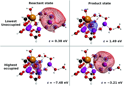
Next, the electronic state analysis along the AIMD path of RL(1) in K04 → K05 at the UHF level (Fig. 12b) supports the view of reloading in the scheme (see Fig. 5). As shown in Fig. 14, the UHF calculation along the path has converged to two states in this case (but not always) with two appropriate choices of initial guess of molecular orbitals (MOs). The total energies calculated with different initial guesses of MOs interchange along the AIMD path as seen in Fig. 13b. This suggests that electron transfer occurs along the path by passing through the nonadiabatic region generated by these two UHF states. We anticipate that such nonadiabatic electron wavepacket dynamics should take place there, if we can practically perform it.
The UHF calculation along with our experience suggests the possible configuration of the active space corresponding to the initial condition of RL(1) in K04 → K05 as
 | (14) |
 | (15) |
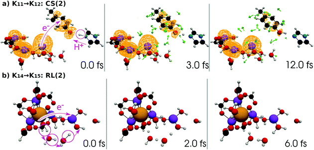 | ||
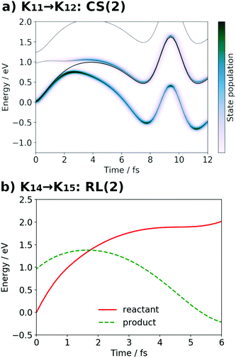
| Fig. 15 (a) Selected snapshots of the spatial distribution of the unpaired electron density D(r) (yellow contour mesh) and electron flux j(r) along a SET path of K11 → K12: CS(2) (SA-MCSCF level). See Fig. 6 for the corresponding chemical scheme. (b) Selected snapshots of an AIMD path of K14 → K15: RL(2) (UHF level). See Fig. 7 for the corresponding chemical scheme. Note that the time t = 0.0 fs is set to the starting time of the dynamics independently, and there is a somewhat long interval between the two subprocesses (a and b). | ||
The interpretation of the dynamics can be given in terms of the active space configurations as follows. The initial condition is written as
 | (16) |
 | (17) |
We can readily guess that the possible configuration of the active space corresponding to the initial condition of RL(2) in K14 → K15 should be
 | (18) |
 | (19) |
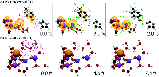 | ||
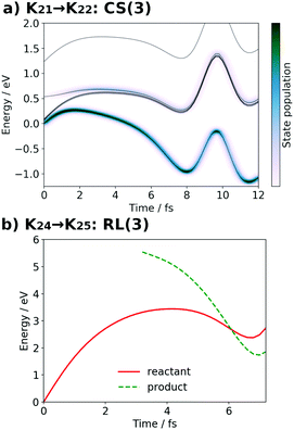
| Fig. 17 (a) Selected snapshots of the spatial distribution of the unpaired electron density D(r) (yellow contour mesh) and electron flux j(r) along a SET path of K21 → K22: CS(3) (SA-MCSCF level). See Fig. 8 for the corresponding chemical scheme. (b) Selected snapshots of an AIMD path of K24 → K25: RL(3) (UHF level). See Fig. 9 for the corresponding chemical scheme. Note that the time t = 0.0 fs is set to the starting time of the dynamics independently, and there is a somewhat long interval between the two subprocesses (a and b). | ||
At time t = 0.0 fs, D(r) is seen on EA, indicating that there exists a 4-methylphenoxy radical. Then it turns into a closed-shell species (i.e., 4-methylphenol), coupling with the PA to EA proton transfer. As shown in Fig. 18a, the time-evolution of the potential energy curves VI and their population |CI|2 also has the same tendency as those of CS(1) in K01 → K11 (Fig. 18a). The ground-state population at t = 12.0 fs is equal to 83%.
The charge separation dynamics can be interpreted in terms of the active space configurations, which are directly guessed from the UHF calculations. The initial condition is written as
 | (20) |
 | (21) |
We can also guess the possible configuration of the active space corresponding to the initial condition of RL(3) in K24 → K25 as
 | (22) |
 | (23) |
 | ||
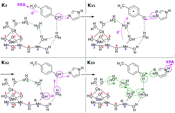
| Fig. 19 Selected snapshots of the spatial distribution of the unpaired electron density D(r) (yellow contour mesh) and electron flux j(r) along a SET path of K31 → K32: CS(4) (SA-MCSCF level). See Fig. 10 for the corresponding chemical scheme. This is the final charge separation in a single cycle. Mn reduction will follow this charge separation to complete one circuit. | ||
At time t = 0.0 fs, D(r) is seen on EA, indicating that there exists a 4-methylphenoxy radical. Then it turns into a closed-shell species (i.e., 4-methylphenol), coupling with the PA to EA proton transfer. As shown in Fig. 20a, the time-evolution of the potential energy curves VI and their population |CI|2 also has the same tendency as those of CS(1) in K01 → K11 (Fig. 20a).
 | (24) |
 | (25) |
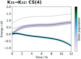 | ||
| Fig. 20 Potential energy curves VI (solid line) and state population |CI|2 (pseudo-color map) along the SET path of K31 → K32: CS(4) (SA-MCSCF level). | ||
In this last stage, we have different dynamics other than the three reloading steps, RL(1) [K04–K05], RL(2) [K14–K15], and RL(3) [K24–K25]. A schematic representation of the final dynamics of water splitting has been illustrated in Fig. 11. Unfortunately, however, the AIMD dynamics with UHF, let alone the nonadiabatic electron dynamics, is too large in computational size to faithfully track the complicated electronic state transitions. This makes a large difference from the water oxidation by the binuclear Mn oxo complex. (As a matter of fact, nonadiabatic electron wavepacket dynamics was carried out for the dynamics of the Mn-reduction process leading to the formation of a spin triplet oxygen molecule in photocatalytic water-splitting by the binuclear Mn oxo complex.22) We therefore can investigate the feasibility of one possible mechanism for water-oxidation only from the viewpoint of energetics. This aspect is visualized with an energy profile in the next subsection, in which not only the O2 generation in the course of K35 to K37 but almost all the other processes are displayed together.
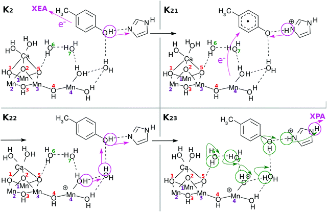
3.4 Energy profile
The dynamical analysis given above has been performed on selected processes such as the charge separation. However, we admit that those dynamical calculations are not long enough to track the connection from one dynamics to the next one. Moreover, such extensive dynamical analyses are technically prohibitive at present due to the extraordinarily severe computational cost. This is particularly the case for reloading dynamics. Besides, it is practically impossible to dynamically track the processes in K03 [Fig. 4], K13 [Fig. 6], K23 [Fig. 8], and K33 [Fig. 10], in which the relay-transferred proton is eventually handed over to an imagined external proton acceptor (XPA) such as P680. The far more challenging task to apply nonadiabatic electron wavepacket dynamics is the process of oxygen generation ranging from K34 to K0 through K35, K36, and K37 [Fig. 11]. We admit that all we can do for these particular stages of the catalytic cycle is to estimate the static energies of the individual Knm. With those energies, we here address the feasibility of the present water-splitting cycle.The electronic energy values for the individual Knm states, as displayed in Fig. 21, have been semiquantitatively estimated as follows. The total energy for each Knm state is a sum of those of the components as shown in the column “Components” of Table 3, each individual component being specified in the square brackets. Those components are assumed to be separated (not physically but mathematically). The spin multiplicity is set to high-spin with respect to the formal oxidation state of the Mn atoms and OH radicals (if any) for the donor components. The spin multiplicity for the acceptor components is set to be either singlet or doublet depending on the state of EA. The total charge is determined from the schematic representation.
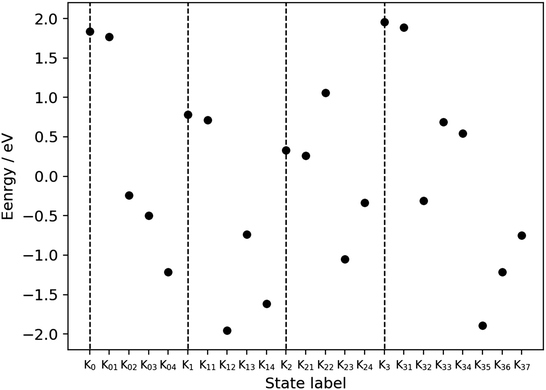 | ||
| Fig. 21 Energy profile for the metastable states of the present water-splitting cycle. Table 3 shows how the energies have been estimated to be compared among the metastable states (Kn and Knm), whose numbers of electrons and nuclei are mutually different. The baseline of the energy is set so that the average of all the points is equal to zero. The energies of Kn5 are not displayed to save space, but they should be exactly or almost equal to Kn+ 1 (n = 0, 1, 2). The total energy is calculated separately for the acceptor (EA and PA) and the other part including EPD, EPR, and some water molecules. The dashed vertical lines mark the positions of Kn (n = 0, 1, 2, 3). | ||
| Metastable state | Components | External |
|---|---|---|
| K0 (Fig. 4) | 21[H3–EPD–H + 3H2O] + 1[EA–H + PA–H] | 0e− + 0H+ |
| K01 (Fig. 4) | 21[H3–EPD–H + 3H2O] + 2[EA + H–PA–H]+ | 1e− + 0H+ |
| K02 (Fig. 4) | 20[H3–EPD–H + 3H2O]+ + 1[EA–H + PA–H] | 1e− + 0H+ |
| K03 (Fig. 4) | 20[H3–EPD + 3H2O] + 1[EA–H + H–PA–H]+ | 1e− + 0H+ |
| K04 (Fig. 5) | 20[H3–EPD + 3H2O] + 1[EA–H + PA–H] | 1e− + 1H+ |
| K1 (Fig. 6) | 20[H2–EPD–H + 3H2O] + 1[EA–H + PA–H] | 1e− + 1H+ |
| K11 (Fig. 6) | 20[H2–EPD–H + 3H2O] + 2[EA + H–PA–H]+ | 2e− + 1H+ |
| K12 (Fig. 6) | 19[H2–EPD–H + 3H2O]+ + 1[EA–H + PA–H] | 2e− + 1H+ |
| K13 (Fig. 6) | 19[H2–EPD + 3H2O] + 1[EA–H + H–PA–H]+ | 2e− + 1H+ |
| K14 (Fig. 7) | 19[H2–EPD + 3H2O] + 1[EA–H + PA–H] | 2e− + 2H+ |
| K2 (Fig. 8) | 19[H–EPD–H + 3H2O] + 1[EA–H + PA–H] | 2e− + 2H+ |
| K21 (Fig. 8) | 19[H–EPD–H + 3H2O] + 2[EA + H–PA–H]+ | 3e− + 2H+ |
| K22 (Fig. 8) | 18[H–EPD–H + 3H2O]+ + 1[EA–H + PA–H] | 3e− + 2H+ |
| K23 (Fig. 8) | 18[H–EPD + 3H2O] + 1[EA–H + H–PA–H]+ | 3e− + 2H+ |
| K24 (Fig. 9) | 18[H–EPD + 3H2O] + 1[EA–H + PA–H] | 3e− + 3H+ |
| K3 (Fig. 10) | 18[EPD–H + 3H2O] + 1[EA–H + PA–H] | 3e− + 3H+ |
| K31 (Fig. 10) | 18[EPD–H + 3H2O] + 2[EA + H–PA–H]+ | 4e− + 3H+ |
| K32 (Fig. 10) | 17[EPD–H + 3H2O]+ + 1[EA–H + PA–H] | 4e− + 3H+ |
| K33 (Fig. 10) | 17[EPD + 3H2O] + 1[EA–H + H–PA–H]+ | 4e− + 3H+ |
| K34 (Fig. 11) | 17[EPD + 3H2O] + 1[EA–H + PA–H] | 4e− + 4H+ |
| K35 (Fig. 11) | 19[H–EPD(OOH) + 2H2O] + 1[EA–H + PA–H] | 4e− + 4H+ |
| K36 (Fig. 11) | 19[H–EPD(OO)–H + 2H2O] + 1[EA–H + PA–H] | 4e− + 4H+ |
| K37 (Fig. 11) | 21[H–EPD(H2O)–H + H2O] + 1[EA–H + PA–H] + 3[O2] | 4e− + 4H+ |
First, we define the molecular “components” that build up each metastable state through Kn and Knm, the AO basis set of which is the same as that used in the dynamics calculations. (See from Fig. 4–11 for each molecular structure of the metastable states.) Note that XEA and XPA are commonly excluded from all the model molecular systems. Note also that the five HCOO groups in EPD are not displayed in the figures of the chemical schemes, although they are taken into account in the energy computation.
The electronic energy of each “component” has been evaluated after geometry optimization based on conventional quantum chemical calculations using the GAMESS program package.60,61 The unrestricted Hartree–Fock (UHF) level of calculations is used so as to be consistent with the ab initio dynamics for the reloading. Accordingly the same atomic basis set is used, that is, the Stevens, Basch, Krauss, Jasien, and Cundari effective core potentials (SBKJC ECPs)62 for Mn and Pople's 6-31G for the other atoms. The optimized energy of the components and that of triplet oxygen as well are tabulated in Section S2 of the ESI.†![[thin space (1/6-em)]](https://www.rsc.org/images/entities/char_2009.gif) 65
65
It is difficult to calculate the entire energy of the whole system shown in the chemical scheme, because biradical states are involved, whose energies tend to be overestimated with the UHF level. Moreover, there is no way to estimate the energy loss or gain at the boundary between EA (PA) and XEA (XPA), simply because we have neither XEA not XPA explicitly. Therefore the energy profile diagram of Fig. 21 is segmented into four natural pieces and the energies have been accordingly estimated as in Table 3. The energy profiles thus estimated should be compared within the individual partitions.
It is seen in Fig. 21 that the subprocess K22 seems to gives a relatively high barrier, but this reaction process is expected to proceed in a concerted manner with the low energy reaction of K23.
As described above, the final stage of our proposed catalytic cycle from K35 to K37 in Fig. 11, where two water molecules are split and triplet oxygen is formed, could not be treated dynamically, and only the energy diagram is available to discuss the feasibility of the model. Fig. 21 shows that the Mn reduction subprocesses (from K35 to K37) seem to require as much as 1.5 eV to proceed. It is highly possible though that this barrier is lowered to some large extent by an expected interaction between the Mn reduction center and newly inserted water molecules, which can take place in a synchronous manner with O2 evolution.
It is finally seen from the energy profile that there are no states of excessively high and low energy.
3.5 Unpaired electron numbers and oxidation numbers
Before concluding the numerical analyses, we track the dynamics of the oxidation states of the Mn cluster on each occasion of the four-step charge separation. To do so without the use of the formal oxidation number, the definition of which is somewhat obscure, we here illustrate the time-evolution of the total number of unpaired electrons ND, which is accumulated from all over the system, and compare it with the Löwdin regional unpaired electron population NLD for the part of the electron and proton donor (EPD) only. Both ND and NLD are time-dependent and their graphs are shown in Fig. 22 for all the four charge separation dynamics.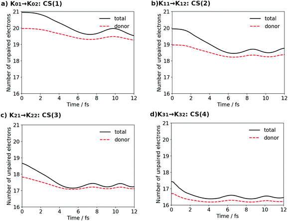 | ||
| Fig. 22 The total number of unpaired electrons ND (solid line) and the Löwdin regional unpaired electron population for the donor NLD (red broken line). | ||
Each panel in the figure demonstrates that NLD for EPD at each t = 0.0 of CS(1) [K01], CS(2) [K11], CS(3) [K21] and CS(4) [K31], respectively, decreases one by one as the formal oxidation state proceeds, reflecting that one electron is transported to XEA on each occasion of charge separation.
The difference between ND and NLD in each panel at t = 0.0 shows that there is one radical electron in EA (see for instance K01 in Fig. 4 after the contact with EA0 (Fig. 3)). This difference tends to converge to zero as the time of the charge separation process proceeds, since a singly-occupied natural orbital in EA, which corresponds to the 4-methylphenoxy radical, is further occupied by another electron that is transported from EPD (Mn cluster). Thus this natural orbital becomes nearly doubly occupied and the radical disappears. (Note however that the differences do not converge exactly to zero in all the cases, mainly because the unpaired electrons reflect also the effects from electron correlation and/or other nonadiabatic interactions.) After some short time, say 12 fs, the unpaired electrons are thus found in the EPD part only. Besides, population analysis shows that the electron loss from EPD is mainly due to the transfer from the 4s-like state on Mn(4), and this 4s-like state is seen to be refilled by an electron from the cubic structure after the reloading process.
Thus the graphs in Fig. 22 suggest that the decrease of the unpaired electrons due to reloading can be linked to the increase of the “oxidation number” of the entire skewed cubic structure (but not to the individual constituent Mn atoms). In fact the combination of ND and NLD has well represented the time-variation of the oxidation process. Thus Fig. 22 together with Fig. 12, 15, 17 and 19 clearly evidences that the electrons used in the four charge separation dynamics are consistently launched solely from Mn(4).
4 Concluding remarks
We have theoretically studied a catalytic cycle as a possible model of water splitting in PSII. The catalyst we chose is Mn4Ca(OH)5(HCOO)5(H2O)4 tied with an electron acceptor (4-methylphenol as a model compound D1-Y161 or TyrZ (YZ)) and also with a proton acceptor (imidazole as a model compound of D1-H190 or HisZ). These molecules are connected through hydrogen bonds due to water clusters. This Mn cluster is appropriately divided as Mn3Ca(H2O)2(OH)4–OH–Mn(4)(H2O)2, where the skewed cubic geometric structure including Mn3CaO4 is fastened by five carboxy groups. Charge separation processes, through which protons and electrons are extracted and transported to the acceptors, have been extensively studied in terms of nonadiabatic electron wavepacket dynamics as the predominantly vital process in biological systems. What we have performed and observed are summarized as follows.We first regard that the present water splitting cycle is triggered by ground-state collision (contact) induced charge separation (chemi-charge-separation). As stated in the Introduction, this is never a trivial assertion, since only the photoinduced charge separation mechanism had been studied quantum mechanically before our concrete identification.20 In collision-induced dynamics, the long time-scale of the total dynamics is determined by the product of the collision frequency and reaction probability at each collision, while the elementary processes such as charge separation are very fast down to the scale of femtoseconds.
As for the molecular geometry, we assumed that the relative orientation of the Mn cluster and the electron and proton acceptors remains loosely fixed. We identify a reaction field in a rather large open space which is surrounded by Mn(4), O(4), Mn(3), O(2), O(5), and Ca. External water molecules are invited into this space, which serve as media of proton relay-transfer at one time and undergo decomposition in other situations.
Then the following phenomena throughout the cycle have been clarified:
(I) Charge separation dynamics, in which the supply of electrons and protons to the acceptors occurs, turns out to be performed four times exclusively through the moiety of Mn(4)(H2O)2 throughout the cycle. The diffuse 4s-like state on Mn(4) is found to be responsible for the electron transfer from the cluster to the electron acceptor.
(II) For this charge-separation dynamics (electron–proton donation from the cluster) to be successfully repeated, intramolecular reconfigurations of the electronic and protonic states should follow appropriately to compensate the loss of electrons and protons, which we called the reloading process. On the occasion of the first three charge transfers, one electron each is transported three times from the skewed cubic Mn3CaO4(H2O)2 to reload Mn(4)+, while it is likely for three protons to be dispatched from two of the hydroxy groups in the skewed cubic structure, O(2)H and O(5)H, and from Ca(H2O)2. All these protons face the reaction field defined above. While the reloading dynamics is definitely needed, it is not stringently determined for protons to be dispatched in what order and how. The flexibility due to the presence of multiple channels of reloading processes should be good for the robustness of living bodies to cope with the fluctuations of nature.
(III) An oxygen molecule is formed after the fourth charge separation is over, the formation energy of which certainly compensates the energy demanded for isolation of four protons and four electrons from two water molecules. Obviously O![[double bond, length as m-dash]](https://www.rsc.org/images/entities/char_e001.gif) O formation is a result of the reloading processes and the reduction of Mn(4)+, and thereby there can exist multiple mechanisms of formation depending on the history of reloading. The mechanisms also should depend on the timing for external water molecules to penetrate into the reaction field. We have proposed one possible mechanism of O2 formation as a closing process of the catalytic cycle. It is quite likely that the mechanisms of O2 formation proposed in the literature can be hardly justified if they have no causality with any dynamics of charge separation and reloading, even if they are correct in a pure chemistry context.
O formation is a result of the reloading processes and the reduction of Mn(4)+, and thereby there can exist multiple mechanisms of formation depending on the history of reloading. The mechanisms also should depend on the timing for external water molecules to penetrate into the reaction field. We have proposed one possible mechanism of O2 formation as a closing process of the catalytic cycle. It is quite likely that the mechanisms of O2 formation proposed in the literature can be hardly justified if they have no causality with any dynamics of charge separation and reloading, even if they are correct in a pure chemistry context.
This work has been a direct extension of our building-block studies on water splitting dynamics starting from mononuclear and binuclear Mn oxo complexes to a tetranuclear Mn oxo complex. It has been observed before that mononuclear Mn oxide alone can work as a unit of both photoinduced and collision-induced ground-state charge separation. Besides, a water splitting catalytic cycle can be constructed in terms of even the mononuclear Mn oxo complex with additional equipment of buffers of electron and protons. As for the binuclear Mn oxo complex, no such external buffers are required to make a catalytic cycle, aside from the efficiency, since one of the two Mn atoms can work as a partial buffer.22 Based on these insights, we now can comprehend (at least partly) how nature makes good use of the tetranuclear complex Mn3Ca(H2O)2(OH)4–OH–Mn(4)(H2O)2: (1) it has an asymmetric binuclear structure, which is what we the call 3 + 1 structure, in which the “3” part corresponds to Mn3Ca(H2O)2(OH)4 and “1” represents Mn(4)(H2O)2. The latter serves as an electrode providing both electrons and protons by the mechanism of coupled proton electron-wavepacket transfer (CPEWT) to the Y-shaped acceptors. The former serves as storage (magazine) of three electrons and three protons, which are sent off to reload the electrode part, that is, the “1” part. Therefore there is no need to prepare buffers of electrons and protons outside the Mn complex. (2) To let the electrode and the acceptors of electrons and protons keep to work, the relative positions of them are weakly fixed.2 (3) The molecular structure of the “3” part is maintained not only by a μ-oxo bridge but by the carboxy groups. The presence of the carboxy groups covering the “3” part tends to prevent it from being accessed by external water molecules. However, the tetranuclear complex has a reaction field in between the “3” and “1” parts, in which to decompose water molecules as described above. For these reasons, the tetranuclear complex must have been far more efficient in evolution.
In this study we could perform real-time nonadiabatic electron wavepacket dynamics only for the four charge separation dynamics. As for the reloading processes, the active space for SA-MCSCF to treat all the Mn atoms on an equal footing was too huge to do so. Instead, we figured out an alternative method to track ab initio molecular dynamics with the use of UHF, the paths of which encounter nonadiabatic crossings. Development of a methodology of electron wavepacket dynamics for a huge active space is a future challenge. For the time being, an energy diagram of the proposed subprocesses has been examined semiquantitatively. We admit that we have a lot more to do for more accurate numerical studies.
Thus, the focus of the present study has been placed on the very basic understanding of the role of Mn4Ca(OH)5(HCOO)5(H2O)4 in water splitting. Yet, further elaboration of the model may be needed to match all the experimental findings thus far reported in the literature, and such sophistication of the model must be useful to design a battery of the mechanism proposed here.
Conflicts of interest
There are no conflicts of interest to declare.Acknowledgements
This work was supported by JSPS KAKENHI (grant number JP15H05752). The computations were partly performed at the Research Center for Computational Science, Okazaki, Japan.References
- P. E. Siegbahn, Acc. Chem. Res., 2009, 42, 1871–1880 CrossRef PubMed.
- Y. Umena, K. Kawakami, J.-R. Shen and N. Kamiya, Nature, 2011, 473, 55–60 CrossRef PubMed.
- M. Suga, F. Akita, K. Hirata, G. Ueno, H. Murakami, Y. Nakajima, T. Shimizu, K. Yamashita, M. Yamamoto, H. Ago and J.-R. Shen, Nature, 2015, 517, 99–103 CrossRef PubMed.
- M. Suga, F. Akita, M. Sugahara, M. Kubo, Y. Nakajima, T. Nakane, K. Yamashita, Y. Umena, M. Nakabayashi, T. Yamane, T. Nakano, M. Suzuki, T. Masuda, S. Inoue, T. Kimura, T. Nomura, S. Yonekura, L.-J. Yu, T. Sakamoto, T. Motomura, J.-H. Chen, Y. Kato, T. Noguchi, K. Tano, Y. Joti, T. Kameshima, T. Hatsui, E. Nango, R. Tanaka, H. Naitow, Y. Matsuura, A. Yamashita, M. Yamamoto, M. Yabashi, T. Ishikawa, S. Iwata and S. Jian-Ren, Nature, 2017, 543, 131–135 CrossRef PubMed.
- I. D. Young, M. Ibrahim, R. Chatterjee, S. Gul, F. D. Fuller, S. Koroidov, A. S. Brewster, R. Tran, R. Alonso-Mori, T. Kroll, T. Michels-Clark, H. Laksmono, R. G. Sierra, C. A. Stan, R. Hussein, M. Zhang, L. Douthit, M. Kubin, C. de Lichtenberg, L. Vo Pham, H. Nilsson, M. H. Cheah, D. Shevela, C. Saracini, M. A. Bean, I. Seuffert, D. Sokaras, T.-C. Weng, E. Pastor, C. Weninger, T. Fransson, L. Lassalle, P. Bräuer, P. Aller, P. T. Docker, B. Andi, A. M. Orville, J. M. Glownia, S. Nelson, M. Sikorski, D. Zhu, M. S. Hunter, T. J. Lane, A. Aquila, J. E. Koglin, J. Robinson, M. Liang, S. Boutet, A. Y. Lyubimov, M. Uervirojnangkoorn, N. W. Moriarty, D. Liebschner, P. V. Afonine, D. G. Waterman, G. Evans, P. Wernet, H. Dobbek, W. I. Weis, A. T. Brunger, P. H. Zwart, P. D. Adams, A. Zouni, J. Messinger, U. Bergmann, N. K. Sauter, J. Kern, V. K. Yachandra and J. Yano, Nature, 2016, 540, 453–457 CrossRef CAS PubMed.
- J. Kern, R. Chatterjee, I. D. Young, F. D. Fuller, L. Lassalle, M. Ibrahim, S. Gul, T. Fransson, A. S. Brewster, R. Alonso-Mori, R. Hussein, M. Zhang, L. Douthit, C. de Lichtenberg, M. H. Cheah, D. Shevela, J. Wersig, I. Seuffert, D. Sokaras, E. Pastor, C. Weninger, T. Kroll, R. G. Sierra, P. Aller, A. Butryn, A. M. Orville, M. Liang, A. Batyuk, J. E. Koglin, S. Carbajo, S. Boutet, N. W. Moriarty, J. M. Holton, H. Dobbek, P. D. Adams, U. Bergmann, N. K. Sauter, A. Zouni, J. Messinger, J. Yano and V. K. Yachandra, Nature, 2018, 563, 421–425 CrossRef CAS PubMed.
- J. Yano and V. Yachandra, Chem. Rev., 2014, 114, 4175–4205 CrossRef CAS PubMed.
- M. Askerka, G. W. Brudvig and V. S. Batista, Acc. Chem. Res., 2016, 50, 41–48 CrossRef PubMed.
- S. Mauthe, I. Fleischer, T. M. Bernhardt, S. M. Lang, R. N. Barnett and U. Landman, Angew. Chem., Int. Ed., 2019, 58, 8504–8509 CrossRef CAS PubMed.
- Y. Zhang, D. Masuzaki and F. Mafuné, Chem. Commun., 2019, 55, 14327–14330 RSC.
- X. Liu, A. L. Sobolewski, R. Borrelli and W. Domcke, Phys. Chem. Chem. Phys., 2013, 15, 5957–5966 RSC.
- W.-J. Ong, L.-L. Tan, Y. H. Ng, S.-T. Yong and S.-P. Chai, Chem. Rev., 2016, 116, 7159–7329 CrossRef CAS PubMed.
- R. Welsch, E. Driscoll, J. M. Dawlaty and T. F. Miller III, J. Phys. Chem. Lett., 2016, 7, 3616–3620 CrossRef CAS PubMed.
- J. Ehrmaier, M. J. Janicki, A. L. Sobolewski and W. Domcke, Phys. Chem. Chem. Phys., 2018, 20, 14420–14430 RSC.
- E. J. Rabe, K. L. Corp, A. L. Sobolewski, W. Domcke and C. W. Schlenker, J. Phys. Chem. Lett., 2018, 9, 6257–6261 CrossRef CAS PubMed.
- X. Pang, C. Jiang, W. Xie and W. Domcke, Phys. Chem. Chem. Phys., 2019, 21, 14073–14079 RSC.
- K. Yamamoto and K. Takatsuka, ChemPhysChem, 2015, 16, 2534–2537 CrossRef CAS PubMed.
- K. Yamamoto and K. Takatsuka, Chem. Phys., 2016, 475, 39–53 CrossRef CAS.
- K. Yamamoto and K. Takatsuka, ChemPhysChem, 2017, 18, 537–548 CrossRef CAS PubMed.
- K. Yamamoto and K. Takatsuka, Phys. Chem. Chem. Phys., 2018, 20, 12229–12240 RSC.
- K. Yamamoto and K. Takatsuka, Phys. Chem. Chem. Phys., 2018, 20, 6708–6725 RSC.
- K. Yamamoto and K. Takatsuka, J. Chem. Phys., 2020, 152, 024115 CrossRef PubMed.
- S. Hammes-Schiffer, Chem. Rev., 2010, 110, 6937–6938 CrossRef CAS PubMed.
- S. Hammes-Schiffer and A. A. Stuchebrukhov, Chem. Rev., 2020, 110, 6939–6960 CrossRef PubMed.
- S. M. Lang, T. M. Bernhardt, D. M. Kiawi, J. S. Bakker, R. N. Barnett and U. Landman, Angew. Chem., Int. Ed., 2015, 54, 15113–15117 CrossRef CAS PubMed.
- Data provided by Prof. Fumitaka Mafune in private communication prior to publication.
- T. Lohmiller, V. Krewald, A. Sedoud, A. W. Rutherford, F. Neese, W. Lubitz, D. A. Pantazis and N. Cox, J. Am. Chem. Soc., 2017, 139, 14412–14424 CrossRef CAS PubMed.
- A. Migliore, N. F. Polizzi, M. J. Therien and D. N. Beratan, Chem. Rev., 2014, 114, 3381–3465 CrossRef CAS PubMed.
- K. Nagashima and K. Takatsuka, J. Phys. Chem. A, 2012, 116, 11167–11179 CrossRef CAS PubMed.
- L. W. Chung, S. Hayashi, M. Lundberg, T. Nakatsu, H. Kato and K. Morokuma, J. Am. Chem. Soc., 2008, 130, 12880–12881 CrossRef CAS PubMed.
- K. Yamamoto and K. Takatsuka, J. Phys. Chem. A, 2019, 123, 4125–4138 CrossRef CAS PubMed.
- P. E. M. Siegbahn, Chem. – Eur. J., 2006, 12, 9217–9227 CrossRef CAS PubMed.
- P. E. M. Siegbahn, Biochim. Biophys. Acta, 2013, 1827, 1003–1019 CrossRef CAS PubMed.
- P. E. M. Siegbahn, Proc. Natl. Acad. Sci. U. S. A., 2017, 114, 4966–4968 CrossRef CAS PubMed.
- H. Isobe, M. Shoji, J.-R. Shen and K. Yamaguchi, Inorg. Chem., 2016, 55, 502–511 CrossRef CAS PubMed.
- M. Shoji, H. Isobe, J.-R. Shen, M. Suga, F. Akita, K. Miyagawa, Y. Shigeta and K. Yamaguchi, Chem. Phys. Lett., 2019, 730, 416–425 CrossRef CAS.
- M. Suga, F. Akita, K. Yamashita, Y. Nakajima, G. Ueno, H. Li, T. Yamane, K. Hirata, Y. Umena and S. Yonekura, et al. , Science, 2019, 366, 334–338 CrossRef CAS PubMed.
- K. Takatsuka, J. Phys. Chem. A, 2007, 111, 10196–10204 CrossRef CAS PubMed.
- T. Yonehara and K. Takatsuka, J. Chem. Phys., 2008, 129, 134109 CrossRef PubMed.
- T. Yonehara, K. Hanasaki and K. Takatsuka, Chem. Rev., 2012, 112, 499–542 CrossRef CAS PubMed.
- K. Takatsuka, T. Yonehara, K. Hanasaki and Y. Arasaki, Chemical Theory Beyond the Born-Oppenheimer Paradigm: Nonadiabatic Electronic and Nuclear Dynamics in Chemical Reactions, World Scientific, Singapore, 2015 Search PubMed.
- H.-D. Meyer and W. H. Miller, J. Chem. Phys., 1979, 70, 3214–3223 CrossRef CAS.
- D. A. Micha, J. Chem. Phys., 1983, 78, 7138–7145 CrossRef CAS.
- A. Garca-Vela, R. Gerber and D. Imre, J. Chem. Phys., 1992, 97, 7242–7250 CrossRef.
- W. H. Miller, Faraday Discuss., 1998, 110, 1–21 RSC.
- M. D. Hack, A. W. Jasper, Y. L. Volobuev, D. W. Schwenke and D. G. Truhlar, J. Phys. Chem. A, 2000, 104, 217–232 CrossRef CAS.
- K. Takatsuka, T. Fueno and K. Yamaguchi, Theor. Chim. Acta, 1978, 48, 175–183 CrossRef CAS.
- R. S. Mulliken, J. Chem. Phys., 1955, 23, 1833–1840 CrossRef CAS.
- P.-O. Löwdin, J. Chem. Phys., 1950, 18, 365–375 CrossRef.
- L. I. Schiff, Quantum mechanics, McGraw-Hill, New York, 1968 Search PubMed.
- K. Nagashima and K. Takatsuka, J. Phys. Chem. A, 2009, 113, 15240–15249 CrossRef CAS PubMed.
- M. Okuyama and K. Takatsuka, Chem. Phys. Lett., 2009, 476, 109–115 CrossRef CAS.
- I. Barth, H.-C. Hege, H. Ikeda, A. Kenfack, M. Koppitz, J. Manz, F. Marquardt and G. K. Paramonov, Chem. Phys. Lett., 2009, 481, 118–123 CrossRef CAS.
- J. Manz, J. F. Pérez-Torres and Y. Yang, J. Phys. Chem. A, 2014, 118, 8411–8425 CrossRef CAS PubMed.
- T. Bredtmann, D. J. Diestler, S.-D. Li, J. Manz, J. F. Pérez-Torres, W.-J. Tian, Y.-B. Wu, Y. Yang and H.-J. Zhai, Phys. Chem. Chem. Phys., 2015, 17, 29421–29464 RSC.
- M. Okuyama and K. Takatsuka, Bull. Chem. Soc. Jpn., 2012, 85, 217–227 CrossRef CAS.
- D. J. Diestler, D. Jia, J. Manz and Y. Yang, J. Phys. Chem. A, 2018, 122, 2150–2159 CrossRef CAS PubMed.
- R. Matsuzaki and K. Takatsuka, J. Comput. Chem., 2019, 40, 148–163 CrossRef CAS PubMed.
- R. Matsuzaki and K. Takatsuka, J. Chem. Phys., 2019, 150, 014103 CrossRef PubMed.
- M. W. Schmidt, K. K. Baldridge, J. A. Boatz, S. T. Elbert, M. S. Gordon, J. H. Jensen, S. Koseki, N. Matsunaga, K. A. Nguyen, S. Su, T. L. Windus, M. Dupuis and J. A. Montgomery, J. Comput. Chem., 1993, 14, 1347–1363 CrossRef CAS.
- M. S. Gordon and W. S. Michael, Theory and Applications of Computational Chemistry: the first forty years, Elsevier, Amsteldam, 2005 Search PubMed.
- W. J. Stevens, M. Krauss, H. Basch and P. G. Jasien, Can. J. Chem., 1992, 70, 612–630 CrossRef CAS.
- B. O. Roos, P. R. Taylor and P. E. M. Siegbahn, Chem. Phys., 1980, 48, 157–173 CrossRef CAS.
- H. J. A. Jensen and H. Ågren, Chem. Phys., 1986, 104, 229–250 CrossRef CAS.
- ESI†.
Footnote |
| † Electronic supplementary information (ESI) available. See DOI: 10.1039/d0cp00443j |
| This journal is © the Owner Societies 2020 |

