 Open Access Article
Creative Commons Attribution 3.0 Unported Licence
On the design of molecular excitonic circuits for quantum computing: the universal quantum gates
Maria A.
Castellanos†
 ,
Amro
Dodin†
 and
Adam P.
Willard
 *
*
Department of Chemistry, Massachusetts Institute of Technology, Cambridge, MA, USA. E-mail: awillard@mit.edu
First published on 13th January 2020
Abstract
This manuscript presents a strategy for controlling the transformation of excitonic states through the design of circuits made up of coupled organic dye molecules. Specifically, we show how unitary transformation matrices can be mapped to the Hamiltonians of physical systems of dye molecules with specified geometric and chemical properties. The evolution of these systems over specific time scales encodes the action of the unitary transformation. We identify bounds on the complexity of the transformations that can be represented by these circuits and on the optoelectronic properties of the dye molecules that comprise them. We formalize this strategy and apply it to determine the excitonic circuits of the four universal quantum logic gates: NOT, Hadamard, π/8 and CNOT. We discuss the properties of these circuits and how their performance is expected to be influenced by the presence of environmental noise.
1 Introduction
The elementary component of a quantum computer – a qubit – is a two-state quantum system. A qubit can be constructed from many different physical systems, including a pair of coupled organic dye molecules sharing a single electronic excitation (i.e., an exciton). Using this kind of qubit it is therefore possible, at least in principle, to develop quantum computing blackelements that operate via the excited state dynamics of specifically designed excitonic circuits comprised of multiple dye molecules in precise geometric arrangements. In this manuscript, we introduce a general strategy for designing excitonic circuits for quantum computation. We apply this strategy to identify fundamental bounds on the computational complexity that these circuits can support and identify the physical requirements for performing universal quantum logic gate operations on one- and two-qubit systems. This study therefore sets the groundwork for enabling the development of programmable dye-based quantum computing blackelements.Excitonic circuits are constructed by arranging the positions and orientations of dye molecules. The evolution of excitons within a circuit is determined by the intermolecular electronic coupling network and the electronic properties of the dyes. The electronic coupling between dye molecules is programmed by their intermolecular spacing and orientation.1 Supermolecular support structures, such as proteins,2,3 metal–organic frameworks,4 and DNA nanostructures,5,6 can be used to situate dye molecules with coupling networks that are designed to control certain aspects of exciton dynamics. The resulting dynamical control can be used to implement the state transformations required for quantum computation.
Quantum computing offers several key advantages over traditional classical computing and is poised to make a transformative impact on certain areas of the information sciences, such as cryptography and molecular simulation.7,8 However, despite enormous potential for broad technological impact, quantum computing presents unique implementation challenges that have thus far limited it to only a few physical systems.9 This includes optical cavities,10,11 trapped ions,12–14 molecular spins,15,16 superconductors,17,18 quantum dots19,20 and solid state color centers.21,22 From the standpoint of quantum computing, each of these qubit systems have their own strengths and limitations. Practical application of any specific system will require exploiting its strengths while mitigating its limitations. Characterizing the strengths and limitations of new potential qubit systems, such as those made from excitonic circuits, is an important step in the development of quantum information technologies.
A limitation that affects nearly all qubit systems is the requirement for low operating temperatures. This requirement is intrinsic to the physics of some systems, such as superconducting and trapped atom qubits. Low temperature is also used to reduce the effects of environmental noise, which can destroy the delicate phase information required for quantum computation. Unfortunately, achieving and maintaining the low temperatures that are required for these systems is both expensive and impractical. Qubit systems with the ability to maintain and share their phase information in noisy thermal environments could significantly improve the scalability of quantum computing technologies.23,24
The dye molecules that comprise excitonic circuits are highly sensitive to environmental noise and exhibit coherence times that are generally much shorter than existing qubit systems. On the other hand, the dye molecules can be strongly coupled so as to enable rapid transfer and evolution of phase information. Viable quantum computing in excitonic circuits will require balancing short coherence times with the ability to produce strong intermolecular electronic couplings. Theoretical models, such as we present here, play an important role in developing an understanding of this balance, its potential implicationsblack, as well as its physical limitations.
We are not the first to propose a molecular system as a platform for quantum computation. Previous studies have explored the use of ultracold diatomic molecules,25–27 and polyatomic molecules,28–32 as quantum computing elements. For the latter, universal gates have been designed and the feasibility of their physical implementation has also been addressed.33 Despite these previous studies, and our own contribution here, many challenges still remain to be solved before such molecular systems can be utilized for quantum computing.
The focus of this paper is to explore the opportunities and limitations in engineering quantum dynamics in excitonic molecular systems. We show that these dynamics can be programmed and exploited to realize a broad range of quantum operations, including, in particular, a universal set of quantum logic gates.34,35 Promisingly, coherent dynamics in excitonic molecular systems are seen to survive moderate levels of environmental noise, suggesting they may be candidates for a new class of quantum materials with information processing applications.
We present a general strategy for programming the dynamics of excitons in the design of excitonic circuits. Importantly, this programming enables the implementation of unitary transformations, such as those that form the basis for quantum information processing. To accomplish this implementation we map qubit states onto the electronic excitation states of coupled dye molecules. For example, the basis states of a two qubit system, i.e., {|00〉,|01〉,|10〉,|11〉}, can be mapped onto a basis of localized single molecule excitations in an excitonic circuit made of four molecules. By representing qubit states as electronic excitations, rather than rotational or vibrational excitations, our approach differs from those that have been proposed previously.
An excitonic representation of a qubit system naturally supports quantum properties such as superposition, i.e., through excitonic delocalization, and can encode coherence and entanglement in multi-qubit systems. It is important to note that the mapping we present here, i.e., whereby each state of a system of qubits is represented by the state of a single exciton in a system of multiple dye molecules, encodes entanglement inefficiently, leading to significant system size scaling problems. However, this scaling problem arises due to the difficulty of representing multi-particle entanglement using a single particle and is therefore a consequence of the limited mapping we propose. As such, more sophisticated mappings that allow multiple excitons can significantly reduce (or altogether eliminate) this issue. However, while a multi-exciton mapping solves the scaling problem, it introduces physical effects, such as exciton–exciton interactions, that significantly complicate theoretical formulation. These complications represent significant future challenges that must be overcome to enable quantum computing through exciton circuits. The work we present here demonstrates how the geometric arrangements of excitonic dyes can be used to encode a quantum transformation, a key first step towards enabling quantum logic operations in excitonic systems.
In the following section we present the details of this strategy and its application to the set of universal quantum logic gates. Then, in Section 3, we simulate the performance of these gates under varying environmental conditions.
2 Mapping unitary transformations onto excitonic circuits
2.1 The Frenkel exciton model
It is convenient to describe the excited state of a N-molecule system in a reduced basis of single molecule excitations. If one then assumes that each molecule can only access one ground and one excited state, then the basis can be represented with that of the Frenkel exciton model.36,37 Specifically, the generic Hamiltonian of the Frenkel model is given by, | (1) |
This simple and computationally efficient model has been widely used in the study of excited multi-chromophoric systems.38–40 Although the Frenkel model omits the influences of higher order excitations, many-body effects, nuclear relaxation, and the specific details of molecular electronic structure, it has been found to be remarkably accurate for reproducing the results of experimental and higher level theory when appropriately parametrized for organic conjugated molecules. We thus employ the Frenkel model in this study, acknowledging that the systems we describe below can be modeled using a higher level theory in subsequent studies, if necessary.
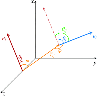
We assume that the configurations of dye molecules in the system are defined by their center of mass positions and orientations. For the purpose of illustration, we assume that the coupling between dye molecules is given by the point dipole approximation,
 | (2) |
 is the transition dipole moment of excitation |i〉, rij =
 ![[r with combining right harpoon above (vector)]](https://www.rsc.org/images/entities/i_char_0072_20d1.gif) i −
i − ![[r with combining right harpoon above (vector)]](https://www.rsc.org/images/entities/i_char_0072_20d1.gif) j is the displacement vector between the dyes,
j is the displacement vector between the dyes, ![[r with combining circumflex]](https://www.rsc.org/images/entities/b_char_0072_0302.gif) ij =
ij = ![[r with combining right harpoon above (vector)]](https://www.rsc.org/images/entities/i_char_0072_20d1.gif) ij/rij is the corresponding displacement unit vector and ε0 is the vacuum permitivity. Alternatively, Vij can be expressed as a function of molecular orientational coordinates as,
ij/rij is the corresponding displacement unit vector and ε0 is the vacuum permitivity. Alternatively, Vij can be expressed as a function of molecular orientational coordinates as, | (3) |
![[r with combining circumflex]](https://www.rsc.org/images/entities/i_char_0072_0302.gif) ij, as illustrated in Fig. 1. Once again, this coupling can be quantified with a less approximate expression if higher accuracy is needed.
ij, as illustrated in Fig. 1. Once again, this coupling can be quantified with a less approximate expression if higher accuracy is needed.
Despite its simplicity, the Frenkel exciton model encodes all of the information of the system dynamics required for the scope of this paper. As we will see in the following sections, the form of the Frenkel Hamiltonian allows us to easily map unitary qubit operations onto excitonic circuit geometries. As has been shown in previous studies,40,41 the details of the molecular structure of the dyes, such as the disorder of the molecular system, can be encoded in the elements of the Hamiltonian. The parameters of the Frenkel Hamiltonian can also be determined from classical all-atom molecular dynamics together with semiempirical electronic structure calculations.40,41
2.2 Engineering exciton dynamics
Molecular excitonic systems with tunable geometry present a unique opportunity to design systems that realize specific quantum transformations. This approach is illustrated in Fig. 2 for schematic quantum circuits. In particular, closed system quantum dynamics generate a family of unitary transformations, , from the system Hamiltonian,
  . A system Hamiltonian,
  , can be represented by a target unitary transformation, Ûtarget, through the relationship,
 | (4) |
 , are scalar multiples that differ only in the transformation time.
Systems comprised of molecular dyes are promising for these applications as their Hamiltonians can be tuned by modifying the spectral properties and geometry of the constituent dyes. Eqn (1)–(4) taken together prescribe a method for designing excitonic circuits that implement a given unitary transformation. Specifically, eqn (1)–(4) define a set of energetic constraints on the coupling and site energies of the dyes while eqn (2) translates these to geometric constraints on the dye assembly. A physical system implementing an unitary transformation, Ûtarget, must therefore satisfy these geometric constraints.
2.3 Example: universal quantum gates
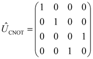
We now illustrate the use of this approach by considering the implementation of a universal set of quantum gates in a dye system. These simple transformations are widely studied as the building blocks of all quantum algorithms. We will show that the one-qubit NOT, Hadamard, and π/8 transformation, and the entangling two-qubit CNOT transformation (shown in Table 1) can be implemented in excitonic dye systems. Moreover, we find that excitonic circuits have far more flexibility than required to realize these transformations, allowing us to design around practical limitations (e.g. limited dye libraries), optimize performance in the presence of noisy environments and even design systems that are easier to prepare and measure with a given experimental set up.Each state |i〉 can be identified in the site basis by the dye molecule where the excitation is localized. Each of these dyes is then associated with a state of the qubit register, mapping the register state to the exciton location. We will then denote each dye by the qubit state from which it is mapped. For a one qubit gate, the qubit states |0〉 and |1〉 are mapped to the states |A〉 and |B〉 of a two dye system (with molecules A and B), respectively, where |A〉 corresponds to the state where only dye A is excited and |B〉 corresponds to the state where only dye B is excited. Likewise, for a two qubit gate the qubit states |00〉,|01〉,|10〉 and |11〉 map to the states |A〉,|B〉,|C〉 and |D〉 of a four dye system. Note that, within this approach, mapping n qubit states will require the preparation of 2n dye molecules, thus providing strong practical limitations on the complexity of quantum computation that can be reasonably represented with an excitonic circuit. For example, the state of a 10-qubit operation requires the use of 1024 dye molecules. Despite this practical limitation, however, the platform that we propose provides an important initial step towards establishing the feasibility of more sophisticated potential approaches. For example, it would be possible to significantly reduce the number of required dye molecules by expanding the framework to include multiple excitations. Because the preparation and spectroscopic analysis of singly-excited systems are more straightforward than those for systems with multiple excitations, the model described in eqn (1) is more appropriate for an initial study for excitonic quantum circuits.
The simplest of these transformations is the π/8 phase gate. This gate increases the relative phase between states |0〉 and |1〉 giving the operation Ûπ/8 and corresponding Hamiltonian in Table 1. This Hamiltonian leads to two intuitive constraints on the dye assembly – one on the coupling and the other one on the relative excitation energy of the dyes. First, since this gate does not induce transitions between qubit states, the dyes must be uncoupled, i.e. V01 = 0. Second, to allow the two states to acquire relative phase, the dyes must be non-degenerate with Δε01 = ε0 − ε1 ≠ 0. These constraints are satisfied by any uncoupled dye heterodimer allowing for any pair of nondegerate dyes and a broad range of possible geometric configurations, as illustrated in Fig. 3C. Moreover, the transformation time is given by τ = π/(4Δε01).
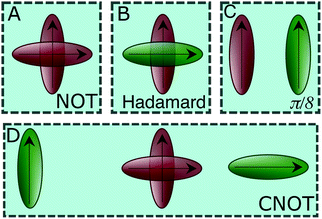 | ||
| Fig. 3 A schematic of the dye circuits representing the four universal quantum gates transformations. | ||
We now consider the single-qubit NOT gate, represented by the unitary operation ÛNOT, in Table 1. This transformation swaps qubit states |0〉 and |1〉 without modifying their relative phase. To ensure excitation transfer the two dyes must have non-zero coupling (i.e. V01 ≠ 0). In addition, they must also be degenerate to ensure that the excitation fully transfers between the states. Thus, any coupled pair of degenerate dyes, e.g., a homodimer, reproduces a quantum NOT gate (Fig. 3A). Physically, this exploits the oscillatory energy transfer in a homodimer to coherently swap qubit states, where the NOT operation is realized at half the Rabi frequency, τ = π/(2V01), when population inversion is maximized.
In a similar way, we can identify a molecular system that represents the action of a Hadamard gate on an input qubit state. This gate is represented by the operator, ÛHad (Table 1). The Hadamard gate transforms an initial state into a superposition of the qubit states |0〉 and |1〉. The system described by  is illustrated in Fig. 3C. This system corresponds to a heterodimer coupled by
  , where the relative transition energies of the dyes are given by
  . We see that
  impose an additional constrain on the system as the ratio of the energy difference, Δε01, and the coupling between the dyes, V01, must be equal to a constant factor: Δε01/V01 = 2. Consequently, the coupling between the dyes in the heterodimer will be completely specified after we choose a value for Δε01, and only a reduced set of dye spatial distributions will evolve with a Hamiltonian
  for such a system.
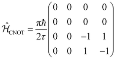
The CNOT gate is an operator that acts over two qubits: one control qubit and one target qubit. If the control qubit is set to zero, then the operator does not act over the target qubit, but if the control qubit is set to 1, then the CNOT operator acts over the target as a NOT gate. The CNOT gate is represented by the 4 × 4 evolution operator, ÛCNOT (Table 1). The control operation is represented in the upper left quarter of ÛCNOT, a 2 × 2 identity matrix, while the NOT operation is represented in the lower right quarter of ÛCNOT. The Hamiltonian that corresponds to this operator is given by  . Correspondingly, a CNOT gate can be realized by a coupled homodimer representing the NOT operation, and two identical uncoupled dyes corresponding to the identity operation, as illustrated in Fig. 3D.
It is important to note that the circuits we propose effectively hard code the action of specific quantum unitary operations. Programmability of these circuits is achieved in their geometric design, thus limiting the flexibility of this platform as a universal quantum computer. For instance, a computation that requires the sequential action of two quantum logic gates on two qubits is represented by a different excitonic circuit than that of either of the individual gates operations. Our study provides a framework for simulating quantum physics and also for designing hard-coded quantum circuits performing pre-determined operations.
2.4 Selective excitation and measurement schemes
In Section 2.3, we found that unitary transformations impose remarkably lenient constraints, allowing for a broad range of possible excitonic circuits. This flexibility can be exploited to construct systems that are easier to experimentally initialize and measure. For two-dimensional operations, such as the one-qubit gates of Section 2.3, selective initialization and measurement of the two sites can be implemented through a polarization addressing scheme. In its most straightforward realization, this addressing approach can be achieved by selecting a configuration where the two dyes have orthogonal transitional dipole moments. Such a configuration is still able to support coupling between the two dyes through the second term of eqn (2). Any desired superposition of sites can then be excited or probed by selecting the appropriate polarization of the excitation or measurement pulse. Real valued superpositions of the two dyes are then addressed by linear polarizations and complex valued superpositions by eliptical polarizations.Four dimensional operations, such as the two qubit CNOT gate, require a slightly generalized strategy since four possible states {|00〉,|01〉,|10〉,|11〉} must be selectively initialized and measured. From  , we know different transition energies are associated with different states of the control qubit (i.e. first qubit). As a result, frequency ω0 addresses the set {|00〉,|01〉}, and frequency ω1 the set {|10〉,|11〉}. This allows the control qubit state to be selectively excited and probed by selecting the frequency of the excitation and probe pulses. Each of these pairs can then be oriented orthogonally to each other, with |00〉 orthogonal to |01〉 and |10〉 orthogonal to |11〉 (Fig. 3D). This arrangement then allows for a polarization addressing of the target qubit state, analogous to the two-dimensional approach.
These addressing strategies are of course not unique. However, they demonstrate how the excess degrees of freedom can be exploited to satisfy additional constraints imposed by experimental limitations (e.g. orthogonality for polarization addressing). Moreover, these constraints can be softened to satisfy other technical constraints. For example, polarization addressed dyes can be placed in non-orthogonal configurations. While this reduces the specificity of the addressing procedure, it can increase the coupling between the dyes, mitigating the effect of environmental noise. In the following section, we explore how dye configurations can be tuned to optimize this type of trade off.
2.5 Bounds on the complexity of a realizable unitary operation
Although eqn (2) provides the geometric constraints for representing a given unitary operation as an excitonic circuit, it is not guaranteed that these can be physically satisfied. For example, it is possible that the number of constraints exceeds the number of degrees of freedom within the geometric design space. In this subsection we enumerate the degrees of freedom available to systems of multiple molecules and thus establish fundamental bounds on the complexity of operation that can be represented by a circuit with a given number of dye molecules.In order to implement an N-dimensional unitary transformation in the single excitation manifold a set of N dyes is required. The diagonal matrix elements of Ûtarget impose N − 1 constrains on the Hamiltonian, after accounting for invariance under the total phase change. These can be satisfied using the N − 1 relative energy degrees of freedom, εi. This leaves N(N − 1) off-diagonal matrix elements that must be satisfied. However, the logarithm of unitary transformations must be anti-Hermitian, indicating that the lower triangle of the matrix can be inferred from the upper triangle, leaving  independent constrains. The freedom of choosing τ introduces a free choice of scaling, which removes one additional constraint.
These constraints must be satisfied by tuning the geometric degrees of freedom of the dye assembly. Each of the N dyes introduces three degrees of freedom corresponding to the dye positions, resulting in 3N degrees of freedom. Each of the N excitations also gives three degrees of freedom corresponding to the orientation of their transition dipole moment, which gives an additional 3N. However, invariance under center of mass translation and total rotation removes a total of 5 of these degrees of freedom. Overall, such a dye assembly provides sufficient flexibility to realize an N-dimensional transformation if,
 | (5) |
This analysis bounds the complexity of transformations that can, in principle, be realized in excitionic systems. However, it assumes a freedom in selecting the positioning, energies and transition dipole moments of the dyes that does not exist in practical applications. Realistically, any given scaffolding approach may have restrictions on dye placement and may only be compatible with a restricted subset of dyes. These practical constraints make the added flexibility of the excess degrees of freedom essential as they can be used to design around the limitations of a given experimental approach. In the remainder of this paper we will show that, at least for simple transformations, the required constraints leave a great deal of flexibility of implementation.
3 Excitonic quantum gates in a phonon bath
3.1 Open system dynamics
Thus far, we have restricted our attention to closed system dynamics where the state of the quantum system can be represented as a linear combination of the form ψ = a0|0〉 + a1|1〉. In this setting, the system is isolated from the surroundings and retains all of its phase information as it evolves in time. However, when a system evolves in contact with a bath, environmental noise and the formation of uncontrolled system-bath entanglement leads to the gradual loss of phase information of the system. In the presence of this incomplete phase information, the state of the quantum system can no longer be represented by a wavefunction. Instead, the system state must be represented by a density matrix ρ.42 In this matrix representation, the diagonal components, ρii, give the population of state |i〉, playing an equivalent role to the probability amplitudes |ai|2. The complex-valued off diagonal components, ρij, are known as coherences and describe the phase information between states |i〉 and |j〉.In the following sections, we will consider the evolution of the one qubit gates in the presence of a noisy environment. This will allow us to examine the limitations and requirements of excitonic quantum information processing and illustrate the optimization of these quantum circuits. By taking advantage of the normalization condition, |α|2 + |β|2 = 1, the density matrix of a two-level qubit can be conveniently represented by the density matrix
 | (6) |
![[small sigma, Greek, vector]](https://www.rsc.org/images/entities/i_char_e1c9.gif) known as the Bloch vector. The properties of the density matrix constrain this vector to the sphere |
known as the Bloch vector. The properties of the density matrix constrain this vector to the sphere |![[small sigma, Greek, vector]](https://www.rsc.org/images/entities/i_char_e1c9.gif) | ≤ 1, which is referred to as the Bloch sphere.
| ≤ 1, which is referred to as the Bloch sphere.
In this compact representation, the evolution of a closed system reduces to solving the set of differential equations for the Bloch vector ![[small sigma, Greek, vector]](https://www.rsc.org/images/entities/i_char_e1c9.gif) , known as the Liouville–von Neumann equations. For a general Hamiltonian of the form H = ε0|0〉〈0| + ε1|1〉〈1| + V01|0〉〈1| + V01*|1〉〈0|, these equations of motion are
, known as the Liouville–von Neumann equations. For a general Hamiltonian of the form H = ε0|0〉〈0| + ε1|1〉〈1| + V01|0〉〈1| + V01*|1〉〈0|, these equations of motion are
 | (7a) |
 | (7b) |
 | (7c) |
 and
and  are the real and imaginary parts of the coupling V01 between the dye molecules, respectively. This yields a unitary evolution that is equivalent to the time-dependent Schrödinger equation.
In an open system, interaction with a noisy environment substantially modifies the system dynamics. Generally, these dynamics can be quite complicated, potentially showing substantial non-Markovian character that depends intricately on the structure and statistics of the environment. In this study, we aim to consider a simple model for the influence of the bath that relies minimally on the details of the local environment. As such, we will restrict our attention to simple phenomenological Markovian master equations of the Lindblad type.42 In this model two major effects are included for a system of dye molecules coupled to a phonon bath. The dephasing, with rate γ, describes random fluctuations in the energy levels of the dye molecules due to environmental noise. This leads to the loss of coherent phase information, manifest in a decay in the off-diagonal components of ρ, or coherences. In addition, dissipation, with rate Γ describes the loss of excitation energy to the phonon bath as the system relaxes to the lower energy eigenstate. Including these dephasing and dissipation effects in eqn (7), we arrive at an expression for the Bloch equations in an open system:
 | (8a) |
 | (8b) |
 | (8c) |
In the following section, we will use eqn (8) to model the dynamics of the NOT and Hadamard gates in order to illustrate the effects of environmental noise on the desired unitary transformation. For simplicity, we will restrict our attention to dyes with linear (as opposed to circular) transition dipole moments. This leads to a real valued coupling between the dyes  .
.
3.2 Gate performance in an environment
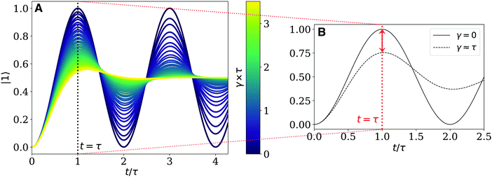
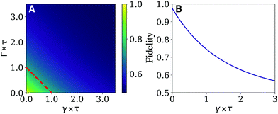
The dynamics of the NOT and Hadamard quantum gates under the effect of phonon bath can be derived by solving the system of equations in eqn (8), using the appropriate Hamiltonian in Table 1. The relative populations of the states of the two-level qubit system in the site basis, as well as the coherences at a a given time, t, can be extracted from the density matrix in eqn (6). As an example, we examine the population dynamics of the NOT gate. Fig. 4A shows the population dynamics of the state |1〉 under the effect of different dephasing rates. In the isolated case, the required state inversion of the input qubit (taking the qubit from |0〉 to |1〉 and from |1〉 to |0〉), is implemented by Rabi oscillations with a period 2τ. This first maximum corresponds to the time it takes the system to perform a single gate operation, before returning again to its initial state, at t = 2τ. The oscillatory nature of the dynamics indicates that for a given configuration the NOT gate transformation is in fact realized at many times, specifically at any τn = nτ, where n is any odd integer. The oscillations in Fig. 4A are seen to decrease rapidly with increasing dephasing rate γ, since the coherence is mostly lost when the dephasing time, 1/γ, is ∼1/3 of τ.The performance of a quantum gate can be quantified according to the schematic in Fig. 4B. In a closed system, a perfect NOT gate would interconvert 100% of the initial qubit between |0〉 and |1〉. However, dephasing (here shown for γ ∼ τ) reduces the amplitude of the Rabi oscillations, decreasing the amount of the excitation transferred to the desired state. At longer times, dephasing fully damps the oscillations leaving an equal (incoherent) mixture of |0〉 and |1〉 states. We therefore want to measure the state of the system at the minimum time it requires to perform the desired operation, τ, and the efficiency must be determined at t = τ (dotted red line in Fig. 4B).
Following this idea, we define a fidelity measure for a two state excitonic circuit that quantifies the probability of measuring the correct outcome after the transformation is applied. This quantity includes the deviation of the state of the open system from that of the closed quantum system at time t = τ and the ability to perform the polarization addressing scheme proposed in Section 2.4. Describing the state of the system at a given time by the density matrix, ρ, in eqn (6), the fidelity of the circuit can be defined by
 | (9) |
![[thin space (1/6-em)]](https://www.rsc.org/images/entities/char_2009.gif) θij, describes the ability of the polarization addressing scheme to distinguish between a pair of dyes when the system is measured. This gives a vanishing fidelity for parallel and anti-parallel dyes (i.e. θij = 0,π) since the two dyes cannot be distinguished by a polarized pulse in these configurations.
θij, describes the ability of the polarization addressing scheme to distinguish between a pair of dyes when the system is measured. This gives a vanishing fidelity for parallel and anti-parallel dyes (i.e. θij = 0,π) since the two dyes cannot be distinguished by a polarized pulse in these configurations.
Equipped with this measure of circuit performance, we now consider the required parameter regime for reliable implementation of two dimensional unitary transformations. To illustrate the effect of dissipation and dephasing on the fidelity of a NOT gate circuit, we use as an example a pair of nearly-orthogonal Cy3 dyes scaffolded in adjacent nucleotide bases:6rij/μ ≈ 0.27 Å D−1, θij = 4π/9 and φ = π/2. The effect is shown in Fig. 5A.
As expected from the dynamics shown in Fig. 4A, the Fidelity of the gate exponentially decays with increasing dephasing and dissipation rates before approaching a 50–50 incoherent mixture of the two states. This yields a fidelity of 0.5 indicating that the correct answer is obtained with the same probability as randomly selecting the output. This corresponds to a circuit that has entirely failed to mimic any unitary transformation. Similarly to the NOT gate, the performance of the Hadamard gate is determined by the computation time scale τ relative to the bath-induced relaxation time. It can be shown that the same behaviour in Fig. 5 can be observed in a Hadamard circuit.
When (Γ + γ)τ > 1, the system has lost its coherence before the gate operation is completed for the first time. Consequently, an excitonic NOT and Hadamard gate will perform well if the computation time, τ, is less than both the dephasing and dissipation times, this is, below the limit (Γ + γ)τ < 1 (red dashed line in Fig. 5A).
Using these observations, it is possible to establish specific bounds on the potential dye systems that can be employed to map a one-qubit unitary transformations. Because these transformations can only be reliably realized if they are completed before bath induced relaxation, (Γ + γ) < 1/τ (red dotted line in Fig. 5) imposes an upper boundary on the allowable computation time. Furthermore, the transformation time, τ, depends on the strength of the coupling (e.g. τ = π/(2V01) for the NOT gate). If the dyes can be placed no closer than some distance rmin, and the orientation of the dyes is set to maximize the coupling from eqn (2) (i.e., θij = π/2 and φ = 0), the coupling is bounded by the expression |V01| ≤ |μA||μB|/4π2ε0r3min. Using these considerations, we propose the following criterion promising excitonic circuits:
 | (10) |
3.3 Optimizing circuit geometry
We now consider optimizing the geometry of excitonic circuits to maximize their Fidelity. Due to the flexibility of the constraints imposed by the unitary transformations many configurations can reproduce the same gate. However, these will generally differ in their computation time and therefore, their sensitivity to environmental noise. For the NOT gate, this time scale is entirely determined by the coupling between the dyes. For simplicity, we will restrict our attention to homodimers with identical dyes since this is the most likely method of achieving degenerate excited states.In this case, μA = μB and the coupling V01 and, consequently, the fidelity will be a function of only the spatial arrangement of the molecular system. We describe the exciton geometry via three parameters: the twist angle, θij, the center-to-center intermolecular distance, rij, and the angle between the dyes and the distance vector, φ, which we assume to be identical for each dye. In realistic systems, the bath contribution is expected to be dominated by the dephasing contribution. As such, we have restricted our attention to purely dephasing baths (i.e. Γ = 0) with a fixed slow dephasing rate γ × τf = 0.8. The parameter τf is calculated from the electronic coupling between a pair of nearly-orthogonal Cy3 dyes at base-pair distance, as in the previous section. This dephasing rate was selected to more clearly show the geometry dependence of the fidelity and is likely to be significantly higher in realistic systems.
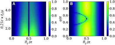
We first consider a pair of dyes comprising a NOT gate that are displaced perpendicular to their dipole moments (i.e. φ = π/2), which sets the second therm in eqn (2) to zero. Fig. 6A shows the dependence of the fidelity of the NOT gate on the spatial terms, rij and θij. Note that the intermolecular distance is presented as a ratio of the transition dipole moment magnitude, μ, in Å D−1 units, with μ = 12 D corresponding to a Cy3 homodimer.
Some interesting patterns in the behaviour of the fidelity should be highlighted from Fig. 6A. We first note two regions where the fidelity is zero for all intermolecular distances: when θij = π/2 and 0, π. In the first case, the dyes are orthogonal to each other, leading to vanishing coupling for all rij. The dye geometry is therefore incapable of satisfying the coupling constraints imposed by the NOT gate transformation. The second case corresponds to a dimer of parallel or antiparallel dyes. In this case, the the dyes can not be distinguished by the polarization addressing scheme. As a result, eqn (9) results in a fidelity of zero when θij = 0, π, for all values of rij. Overall, the dependence of the fidelity on the interchromophore angle, θij, demonstrates a trade-off between the cos![[thin space (1/6-em)]](https://www.rsc.org/images/entities/char_2009.gif) θij and sin2
θij and sin2![[thin space (1/6-em)]](https://www.rsc.org/images/entities/char_2009.gif) θij terms, with a maximum fidelity at a critical point close to θij = π/2, as evident in Fig. 6A.
θij terms, with a maximum fidelity at a critical point close to θij = π/2, as evident in Fig. 6A.
The effect of the interchromophore distance, rij, on the fidelity is contained in the term 1/r3ij in eqn (2). As a result, we see that the coupling and the fidelity monotonically decrease with increasing distance between the dyes. In this case, the optimal geometry simply minimizes distance subject to experimental constraints.
A more complete picture of geometry arrangement emerges when φ is allowed to vary. Fig. 6B presents the behaviour of the fidelity when θij and φ are varied at a fixed ratio of 0.21e × rij/μ = 1.29 and the same bath conditions as panel A. In this case, the coupling contains contributions form the second term in eqn (2), allowing for V01 ≠ 0 when θij = π/2. As a result, the maximum fidelity can now be reached with orthogonal dyes as this circumvents the tradeoff between coupling and measurement specificity inherent to the φ = π/2 case treated above. Similarly to Fig. 6A, a sharp line can be seen with rapidly decreasing fidelity where the dyes are uncoupled. Since the coupling depends on both angles, this is no longer a straight line and instead appears as the curved line in Fig. 6B given by μA·μB = 3(μA·![[r with combining circumflex]](https://www.rsc.org/images/entities/i_char_0072_0302.gif) ij)(μB·
ij)(μB·![[r with combining circumflex]](https://www.rsc.org/images/entities/i_char_0072_0302.gif) ij).
ij).
Optimizing the performance of the Hadamard gate is slightly more straightforward than the CNOT gate. From tbl:gates we can note that the coupling of the Hadamard gate is constrained by the ratio Δε01/V01 = 2. As a result, τ and therefore the fidelity can be determined by comparing the relative energy between the dye molecules. It is therefore straightforward to show that, as long as the required coupling is achievable for a given pair of dyes, it is optimal to select a dye configuration with angle θij = π/2 in order to maximize the selectivity of polarization addressing. Fig. 7 illustrates the dependence of the fidelity on the difference between the individual excitation energies of the dyes, Δε01, for a fixed bath with Γ = 0 and γ × τf = 0.8. We can see that the Fidelity increases rapidly with the energy difference, as the coupling also increases proportionally. However, we note that, as described by eqn (10), the dipole moments and the achievable dye configurations provide a bound for the maximum coupling that can be implemented in the dye system. This limits the energy differences of dyes that can be used, capping the achievable Fidelity of a given circuit.
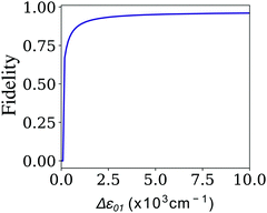 | ||
| Fig. 7 Fidelity of the Hadamard quantum gate. Fidelity as a function of the difference between the individual excitation energies of each dye in the heterodimer comprising the excitonic system. | ||
4 Conclusions
In this manuscript, we have proposed a general strategy for mapping specific unitary operations onto excitonic cricuits. We show that this strategy is limited in complexity to 12 dimensional or smaller quantum systems. However, these systems exhibit a manifold of possible excitonic circuits that are able to generate them. We show that these excess degrees of freedom can be exploited to facilitate experimental initialization and measurement and to mitigate the effect of environmental noise. Moreover, we identify a criterion for molecular parameters that identify dye-scaffolding systems that may be promising for quantum information applications.Conflicts of interest
There are no conflicts to declare.Acknowledgements
This work was supported by the National Science Foundation (A. D.) under award number CHE-1839155 and the US Department of Energy (M. A. C.) under award number DE-SC0019998. A. D. acknowledges additional support from the Natural Science and Engineering Research Council of Canada Postgraduate Scholarship Doctoral (NSERC PGSD) program, M. A. C. acknowledges additional support from the Amy Lin Shen Fellowship, and A. W. acknowledges support from the Research Corporation for Scientific Advancement (Cottrell Scholar).References
- M. Cho, Two-dimensional optical spectroscopy, CRC Press, 2009, p. 378 Search PubMed.
- G. D. Scholes, G. R. Fleming, A. Olaya-Castro and R. van Grondelle, Nat. Chem., 2011, 3, 763–774 CrossRef CAS.
- C. P. Dietrich, M. Siegert, S. Betzold, J. Ohmer, U. Fischer and S. Höfling, Appl. Phys. Lett., 2017, 110, 043703 CrossRef.
- H.-J. Son, S. Jin, S. Patwardhan, S. J. Wezenberg, N. C. Jeong, M. So, C. E. Wilmer, A. A. Sarjeant, G. C. Schatz, R. Q. Snurr, O. K. Farha, G. P. Wiederrecht and J. T. Hupp, J. Am. Chem. Soc., 2013, 135, 862–869 CrossRef CAS PubMed.
- É. Boulais, N. P. D. Sawaya, R. Veneziano, A. Andreoni, J. L. Banal, T. Kondo, S. Mandal, S. Lin, G. S. Schlau-Cohen, N. W. Woodbury, H. Yan, A. Aspuru-Guzik and M. Bathe, Nat. Mater., 2017, 17, 159 CrossRef PubMed.
- L. Kringle, N. P. D. Sawaya, J. Widom, C. Adams, M. G. Raymer, A. Aspuru-Guzik and A. H. Marcus, J. Chem. Phys., 2018, 148, 085101 CrossRef PubMed.
- D. Deutsch, A. Ekert, R. Jozsa, C. Macchiavello, S. Popescu and A. Sanpera, Phys. Rev. Lett., 1996, 77, 2818–2821 CrossRef CAS PubMed.
- J. Olson, Y. Cao, J. Romero, P. Johnson, P.-L. Dallaire-Demers, N. Sawaya, P. Narang, I. Kivlichan, M. Wasielewski and A. Aspuru-Guzik, Quantum Information and Computation for Chemistry, 2017 Search PubMed.
- D. P. DiVincenzo, Fortschr. Phys., 2000, 48, 771–783 CrossRef.
- J. L. O'Brien, Science, 2007, 318, 1567–1570 CrossRef PubMed.
- F. Flamini, N. Spagnolo and F. Sciarrino, Rep. Prog. Phys., 2019, 82, 016001 CrossRef CAS PubMed.
- J. I. Cirac and P. Zoller, Phys. Rev. Lett., 1995, 74, 4091–4094 CrossRef CAS PubMed.
- M. Anderlini, P. J. Lee, B. L. Brown, J. Sebby-Strabley, W. D. Phillips and J. V. Porto, Nature, 2007, 448, 452–456 CrossRef CAS PubMed.
- N. Friis, O. Marty, C. Maier, C. Hempel, M. Holzäpfel, P. Jurcevic, M. B. Plenio, M. Huber, C. Roos, R. Blatt and B. Lanyon, Phys. Rev. X, 2018, 8, 021012 CAS.
- N. Gershenfeld and I. L. Chuang, Sci. Am., 1998, 278, 66–71 CrossRef CAS.
- A. Gaita-Ariño, F. Luis, S. Hill and E. Coronado, Nat. Chem., 2019, 11, 301–309 CrossRef.
- G. Wendin, Rep. Prog. Phys., 2017, 80, 106001 CrossRef CAS PubMed.
- IBM Q Experience. https://quantumexperience.ng.bluemix.net/qx/deprecated.
- T. D. Ladd, F. Jelezko, R. Laflamme, Y. Nakamura, C. Monroe and J. L. O'Brien, Nature, 2010, 464, 45–53 CrossRef CAS PubMed.
- D. Loss and D. P. DiVincenzo, Phys. Rev. A: At., Mol., Opt. Phys., 1998, 57, 120–126 CrossRef CAS.
- V. Acosta and P. Hemmer, MRS Bull., 2013, 38, 127–130 CrossRef CAS.
- X.-Y. Chen and Z.-q. Yin, Phys. Rev. A, 2019, 99, 022319 CrossRef CAS.
- B. Náfrádi, M. Choucair, K.-P. Dinse and L. Forró, Nat. Commun., 2016, 7, 12232 CrossRef PubMed.
- A. L. Exarhos, D. A. Hopper, R. N. Patel, M. W. Doherty and L. C. Bassett, Nat. Commun., 2019, 10, 222 CrossRef PubMed.
- D. DeMille, Phys. Rev. Lett., 2002, 88, 067901 CrossRef CAS.
- S. F. Yelin, K. Kirby and R. Côté, Phys. Rev. A: At., Mol., Opt. Phys., 2006, 74, 050301 CrossRef.
- K. Mishima and K. Yamashita, Chem. Phys., 2009, 361, 106–117 CrossRef CAS.
- U. Troppmann, C. M. Tesch and R. De Vivie-Riedle, Chem. Phys. Lett., 2003, 378, 273–280 CrossRef CAS.
- C. Gollub, U. Troppmann and R. De Vivie-Riedle, New J. Phys., 2006, 8, 48 CrossRef.
- D. Babikov, J. Chem. Phys., 2004, 121, 7577–7585 CrossRef CAS PubMed.
- E. Berrios, M. Gruebele, D. Shyshlov, L. Wang and D. Babikov, J. Phys. Chem. A, 2012, 116, 11347–11354 CrossRef CAS PubMed.
- M. Zhao and D. Babikov, J. Chem. Phys., 2007, 126, 204102 CrossRef PubMed.
- D. Shyshlov and D. Babikov, J. Chem. Phys., 2012, 137, 194318 CrossRef PubMed.
- M. A. Nielsen and I. L. Chuang, Quantum Computation and Quantum Information: 10th Anniversary Edition, Cambridge University Press, Cambridge, New York, 2011 Search PubMed.
- P. R. Kaye, R. Laflamme and M. Mosca, An introduction to Quantum Computing, Oxford University Press, New York, 1st edn, 2007 Search PubMed.
- J. Frenkel, Phys. Rev., 1931, 37, 17–44 CrossRef CAS.
- A. S. Davydov, Phys. – Usp., 1964, 7, 145–178 CrossRef.
- E. R. Bittner, J. Photochem. Photobiol., A, 2007, 190, 328–334 CrossRef CAS.
- F. C. Spano, Annu. Rev. Phys. Chem., 2006, 57, 217–243 CrossRef CAS PubMed.
- L. Shi and A. P. Willard, J. Chem. Phys., 2018, 149, 94110 CrossRef PubMed.
- C. K. Lee, L. Shi and A. P. Willard, J. Phys. Chem. C, 2019, 123, 306–314 CrossRef CAS.
- K. Blum, Density matrix theory and applications, Springer Series on Atomic Optical and Plasma Physics, Springer, Berlin, 3rd edn, 2012 Search PubMed.
- J. M. Berg, J. L. Tymoczko and L. Stryer, Primary Structure: Amino Acids Are Linked by Peptide Bonds to Form Polypeptide Chains, W H Freeman, New York, 5th edn, 2002 Search PubMed.
Footnote |
| † Contributed equally. |
| This journal is © the Owner Societies 2020 |

