
Redox-mediated transformation of a Tb2O3(111) thin film from the cubic fluorite to bixbyite structure†
Christopher J.
Lee
 ,
Ameen
Sayal
,
Saumye
Vashishtha
and
Jason F.
Weaver
*
,
Ameen
Sayal
,
Saumye
Vashishtha
and
Jason F.
Weaver
*
Department of Chemical Engineering, University of Florida, Gainesville, FL 32611, USA. E-mail: weaver@che.ufl.edu; Fax: +1-352-392-9513; Tel: +1-352-392-0869
First published on 2nd December 2019
Abstract
We used temperature programmed desorption (TPD) and low energy electron diffraction (LEED) to investigate the isomeric structural transformation of a Tb2O3 thin film grown on Pt(111). We find that repeated oxidation and thermal reduction to 1000 K transforms an oxygen-deficient, cubic fluorite (CF) Tb2O3(111) thin film to the well-defined bixbyite, or c-Tb2O3(111) structure, whereas annealing the CF-Tb2O3(111) film in UHV is ineffective in causing this structural transformation. We estimate that the final stabilized film consists of about ten layers of c-Tb2O3(111) in the surface region plus about eight layers of CF-Tb2O3(111) located between the c-Tb2O3(111) and the Pt(111) substrate. Our measurements reveal the development of two distinct O2 TPD peaks during the CF to bixbyite transformation that arise from oxidation of c-Tb2O3 domains to the stoichiometrically-invariant ι-Tb7O12 and δ-Tb11O20 phases and demonstrate that the c-Tb2O3 phase oxidizes more facilely than CF-Tb2O3. We present evidence that nucleation and growth of c-Tb2O3 domains occurs at the buried TbOx/CF-Tb2O3 interface, and that conversion of the interfacial CF-Tb2O3 to bixbyite takes place mainly during thermal reduction of TbOx above ∼900 K and causes newly-formed c-Tb2O3 to advance deeper into the film. The avoidance of low Tb oxidation states may facilitate the CF to bixbyite transformation via this redox mechanism.
Introduction
The rare earth oxides (REOs) exhibit favorable properties for various applications of oxidative catalysis including complete and partial oxidation,1,2 hydrogenation and dehydrogenation,3–5 coupling reactions,6–10 and the selective reduction of NO11–13 to name a few.14–17 Though rare earth oxide surfaces can be effective in promoting various oxidation reactions, developing an understanding of the reaction mechanisms at the atomic level is challenging due to the highly dynamic nature of the REO structures and sensitivity to changes in oxidative environment.18–20Within the family of rare earth metals, only Ce, Pr, and Tb are known to form stable oxide phases beyond the sesquioxide (Ln2O3) and up to the dioxide (LnO2) stoichiometry, allowing for the flexible storage and release of lattice oxygen necessary to facilitate redox chemistry. As lattice oxygen can participate directly in surface interactions through the Mars–van-Krevelen mechanism, sustained oxidative activity of these structures is largely dependent on their characteristic lattice oxygen mobility and ability to transform between reduced and oxidized phases.21–23 This last note is especially promising for applications involving terbium oxide and praseodymium oxide since these oxides have the highest oxygen mobilities documented for REOs.24 Bulk oxides of Tb, Pr and Ce can also form in stoichiometries that are intermediate to Ln2O3 and LnO2, with structures that feature either randomly-distributed oxygen vacancies or long-range ordered vacancies, depending upon conditions. These structures include a homologous series of well-defined intermediate phases in the form of LnnO2n−2 (n = 4, 6, 7, 9, 11, 12, and ∞) in addition to a continuum of seemingly nonstoichiometric states adopting an oxygen-deficient fluorite structure.18,25
Thin films of REOs grown on metal substrates have served as model systems for characterizing the surface structural and chemical properties of REOs, with ceria being the most widely studied REO thin film. These prior studies demonstrate that ceria oxidizes readily and forms the cubic fluorite (CF) CeO2(111) structure on hexagonally close-packed metal surfaces during film growth in an O2 background in UHV.26–32 Thermal reduction of these CeO2(111) films as well as reduction by adsorbed reactants (e.g., CH3OH) typically produces oxygen-deficient CF-CeOx(111) in which the oxygen vacancies are randomly distributed.23,33,34 Several reports show that solid-state reactions between layers of Ce metal and CeO2 and also slow CeOx(111) reduction by H2 can produce intermediate, stoichiometric CeOx phases, including ordered structures of c-Ce2O3, Ce3O5 and ι-Ce7O12.35–38 Recent work also demonstrates that complete oxidation of an c-Pr2O3(111) film followed by thermal reduction in UHV produces the h-Pr2O3(0001) structure, thus enabling surface science investigations of distinct Pr2O3 surface structures.39–41 These prior studies reveal that the development of intermediate, ordered phases of REO films can be quite sensitive to the film growth and redox conditions.
We have previously shown that terbia thin films grown on Pt(111) in an O2 background form in the Tb2O3 stoichiometry and adopt a cubic fluorite (3 × 3) structure,16 in contrast to h-Pr2O3(0001)39,41–43 and CeO2(111) films prepared under similar conditions.20,35 Excellent lattice matching with the Pt(111) substrate likely stabilizes the CF-(3 × 3) structure of the CF-Tb2O3(111) films and distinguishes the TbOx/Pt(111) thin film system from other reduced REO thin film systems. These Tb2O3 films can be oxidized extensively by O-atoms at 300 K, allowing for variation in oxidation state of the system.15 However, this prior work shows that oxidation of CF-Tb2O3 leads directly to CF-TbOx without the formation of well-defined intermediate phases such as the iota and delta phases, and that thermal reduction at ∼900 K restores the oxygen-deficient CF-Tb2O3 structure rather than generating the c-Tb2O3 phase that is preferred in bulk Tb2O3.
In the present study, we report that a CF-Tb2O3(111) film on Pt(111) transforms to a well-ordered bixbyite c-Tb2O3(111) structure after repeated oxidation and thermal reduction to 1000 K, whereas the CF-Tb2O3(111) structure remains unchanged during prolonged annealing in UHV. We further present evidence that oxidation of the c-Tb2O3(111) film occurs more facilely than CF-Tb2O3(111) and occurs through the sequential formation of the stoichiometric iota (ι-Tb7O12) and delta (δ-Tb11O20) phases. Our results reveal that additional lattice oxygen accommodated within the film facilitates the transition between the isomeric CF and bixbyite Tb2O3(111) structures, and may shed light into the nature of lattice oxygen exchange in other sesquioxides within the family of REOs.
Experimental details
Experiments for this study were carried out in a three-level ultrahigh vacuum (UHV) chamber with a typical base pressure of 2 × 10⁻¹⁰ Torr. The details for this system are documented in prior studies.44–46 Briefly, the chamber is equipped with a RF plasma source (Oxford Scientific Instruments) for generating atomic oxygen beams, a low energy electron diffraction (LEED) optics (SPECS) for characterization of surface structure, a quadrupole mass spectrometer (QMS) (Hiden) for temperature-programmed desorption (TPD) measurements, and a dual Mg/Al anode X-ray source and hemispherical analyzer (SPECS) for X-ray photoelectron spectroscopy (XPS) measurements. The plasma source is housed in a two-stage differentially-pumped beam chamber that connects to the UHV analysis chamber.The Pt(111) crystal utilized in this study is a circular disk (10 mm × 1 mm) that was supported by tungsten wires fed through grooves located at the top and bottom edges of the crystal. The wires are held in thermal contact with a liquid nitrogen cooled copper reservoir and can be resistively heated. A type K thermocouple is spot welded to the back of the sample, and DC current supplied to the tungsten wires, regulated by a PID controller, allows for sample temperature control between the range of ∼89 K to 1100 K. We cleaned the sample by sputtering the surface with 600 eV Ar+ ions at an elevated temperature of 600 K and post annealing the sample to 1000 K. We also find that cycling the sample between 300 K and 1000 K in 5 × 10⁻⁷ Torr of O2 is particularly effective at removing surface carbon and other adsorbed species. We considered the sample to be clean when we observed negligible levels of carbon and oxygen in XPS (C 1s and O 1s peaks) as well as negligible amounts of CO and CO2 evolution during TPD.
We grew terbium oxide films by the reactive physical vapor deposition (RPVD) of terbium metal (Alfa Aesar, 99.9%) onto the clean Pt(111) substrate. We vaporized Tb metal from a Ta crucible using an e-beam evaporator (McAllister Technical services) and deposited in an O2 background of 5 × 10⁻⁷ Torr. We held the sample at 600 K during deposition followed by post annealing of the film at 1000 K in the same oxygen background. This approach has proven to be effective for improving the overall crystallinity of the initial Tb2O3 film2,16,47 as well as preparing high-quality thin films of other rare earth oxides including Sm2O3(111)14 and CeO2(111).48 We estimate that the average deposition rate was 0.13 ± 0.02 layer per min of Tb2O3. In this study, one layer is defined in reference to bulk c-type Tb2O3 as the O–Tb–O trilayer separation in the [111] direction. This corresponds to a height of 3.01 Å and a Tb density of 8.57 × 1014 cm−2 per layer. We estimated film thicknesses from measurements of the attenuation of the Pt 4f XPS peak intensity. We estimate an inelastic mean free path (IMFP) of 26.9 Å for the Pt 4f photoelectrons through TbOx using an average of the IMFP values determined from the TPP-2M and Gries equations for an electron kinetic energy of 1415 eV.49
We oxidized the Tb2O3 films using plasma-generated O-atom beams and investigated the oxidized films using LEED, XPS and TPD. We estimate an O-atom flux of 0.018 ML s−1 for these experiments based on TPD measurements of oxygen uptake by Pt(111). We found that flashing the TbOx films to 900 K and 1000 K prior to any O atom exposures was sufficient to remove surface contamination and reduce the film to a reproducible level, consistent with the Tb2O3 stoichiometry (see below). After an O-atom exposure, we positioned the sample in front of a shielded mass spectrometer at a distance of ∼5 mm and heated at a constant rate of 1 K s−1 until reaching a sample temperature of 900 or 1000 K. We estimate the absolute desorption yields of O2 on the basis of O2 TPD spectra taken after oxygen adsorption onto Pt(111). A saturation exposure to background O2 at 300 K generates a (2 × 2)-O layer on Pt(111) with a coverage of 0.25 O-atoms per surface Pt atom. We estimate an uncertainty of about 5% in the absolute O2 coverages based on this approach. We define 1 ML (monolayer) of O-atoms as equal to the density of Tb atoms in one O–Tb–O trilayer of TbO2(111), and report O2 TPD yields in these units. This coverage scale provides a convenient metric for stoichiometric analysis as a single O–Tb–O trilayer of TbO2(111) contains 2 ML of O atoms and 1 ML of Tb atoms, and 0.5 ML of O-atoms are needed to completely oxidize a single trilayer of Tb2O3 to TbO2. We performed XPS experiments using Al Kα X-rays and collected spectra using a hemispherical analyzer with a pass energy of 27 eV. The data here is presented after averaging 20 scans and applying a linear background subtraction over the range of collected spectra.
Results
Oxidation of CF-Tb2O3(111)
Fig. 1a shows O2 TPD traces obtained after oxidizing an ∼18-layer CF-Tb2O3(111) film to varying extents at 300 K using an O-atom beam, and limiting the final temperature to 900 K during the measurements. Fig. 1b shows the corresponding oxygen uptake by the CF film as a function of the exposure time. As mentioned in experimental details, we have previously shown that the as-deposited Tb2O3 film forms in the oxygen-deficient CF structure, and that oxygen vacancies arrange into a (3 × 3) superstructure at the surface of films of thickness greater than ∼5 layers (Fig. 2a).16 We have also previously shown that CF-Tb2O3(111) grows epitaxially on Pt(111) and adopts an (3 × 3)/(4 × 4) coincident structure with minimal strain, and suggested that this favorable CF-Tb2O3(111)/Pt(111) interface likely mediates formation of a (3 × 3) arrangement of surface vacancies in thick films.16 Similar to previous results,2,15 the O2 TPD traces exhibit two broad features centered at 370 K and 670 K that have been attributed to oxygen evolving from the surface and bulk of the oxidized film, respectively. These features populate nearly simultaneously as a function of the total oxygen uptake. A small peak at 770 K also becomes evident as the oxygen uptake approaches saturation. We attribute this small peak to the decomposition of crystalline ι-Tb7O12 domains in the bulk of the film (see below). We also note that the O2 desorption rate remains appreciable at 900 K when the TPD experiment ends. This characteristic appears to play an important role in promoting restructuring as discussed below. Oxygen uptake by the CF film saturates at about 1.25 ML for oxidation at 300 K. This value is surprisingly low as it is equivalent to completely oxidizing only about 2.5 layers of Tb2O3 to TbO2, whereas we estimate that the film is about 18 layers thick. We thus conclude that only layers near the vacuum-oxide interface oxidize under the conditions studied.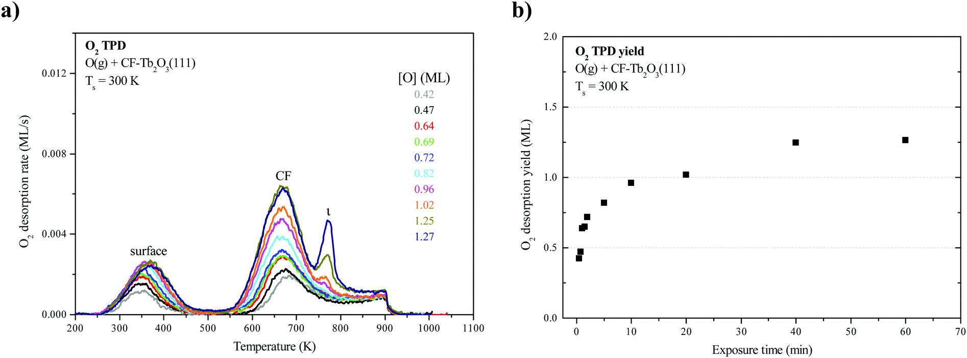 | ||
| Fig. 1 (a) O2 TPD spectra obtained as a function of the oxygen uptake by an ∼18 layer CF-Tb2O3(111) film on Pt(111) during exposure to an O-atom beam at 300 K. Heating was discontinued at 900 K for each TPD experiment. (b) Oxygen uptake expressed in ML of O-atoms as a function of the exposure time of the CF-Tb2O3(111) film to atomic oxygen. | ||
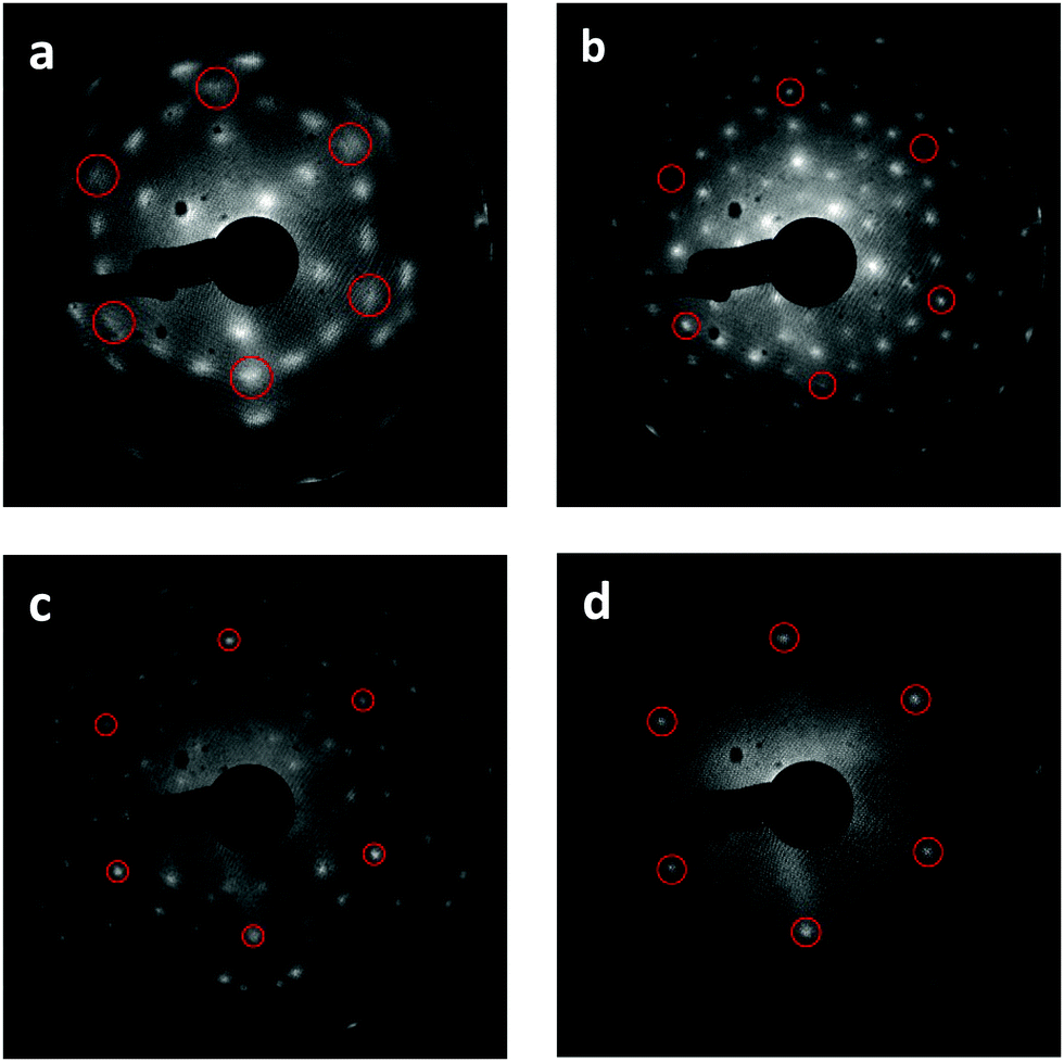 | ||
| Fig. 2 Development of stable bixbyite Tb2O3 film and higher ordered intermediate structures. Reference LEED images taken at 95 eV shown after (a) initial RPVD of 18 trilayer (3 × 3) CF-Tb2O3(111) film, (b) (4 × 4) c-Tb2O3(111) structure obtained after ten cycles of O-atom exposure followed by TPD from 300 to 1000 K, (c) (√7 × √7)R19.1° structure for ι-Tb7O12(111) observed after 20 minute O-atom exposure at 300 K, and heating to 700 K, and (d) TbO2(111) film stabilized by 20 minute O-atom exposure at 300 K. The circles mark the reciprocal space positions of the CF-TbOx(111)-(1 × 1) unit cell. | ||
LEED from TbOx(111) structures
We find that repeated oxidation and reduction by heating to 1000 K during TPD induces a structural transformation of the Tb2O3(111) film such that the cubic fluorite (CF) structure transforms into a well-ordered c-Tb2O3(111) structure, i.e., bixbyite. We obtained the LEED patterns in Fig. 2a and b from the initial CF-Tb2O3(111) film and after oxidizing and reducing the film to 1000 K ten times, where each oxidation step was performed at 300 K and involved an O-atom exposure of ∼60 ML. The initial Tb2O3(111) surface exhibited a (3 × 3) pattern with broad spots (Fig. 2a), consistent with our earlier findings.16 While the CF-(3 × 3) structure persists after annealing to 1000 K in UHV or low O2 pressures, the Tb2O3(111) surface obtained after the repeated oxidation/reduction steps (10×) exhibits a sharp (4 × 4) LEED pattern in the CF-TbOx(111) basis (Fig. 2b) consistent with c-Tb2O3(111). Prior studies report that the c-Ce2O3(111) surface also generates a (4 × 4) LEED pattern.34,35,37 The c-Tb2O3(111) unit cell exhibits three-fold symmetry, resembling a hexagonal lattice, with lattice constants that are four times larger than the CF-TbOx(111) unit cell,18 and thus gives a (4 × 4) LEED pattern in the TbOx(111) basis. The much sharper spots in the (4 × 4) vs. (3 × 3) LEED pattern indicate that the oxidation/reduction steps improve the crystallinity of the Tb2O3 film such that the crystalline domains of the bixbyite structure are larger than those of the original cubic fluorite structure. Fig. 2c and d show LEED patterns obtained after oxidizing the c-Tb2O3(111) film under different conditions, as discussed below.O2 TPD during the cubic fluorite to bixbyite Tb2O3(111) transformation
We collected an O2 TPD spectrum after each oxidation treatment to monitor how the oxygen uptake and desorption behavior evolve as the film transforms from CF to bixbyite. Fig. 3a shows O2 TPD spectra obtained after successively oxidizing the Tb2O3(111) film by exposure to 60 ML O-atoms at 300 K, and allowing the final temperature to reach 1000 K during each TPD measurement while Fig. 3b shows the corresponding oxygen uptake. The TPD features arising from bulk oxide decomposition change significantly with each oxidation step, until stabilizing after ten steps. After the first oxidation step, bulk oxide decomposition produces a broad feature centered at about 670 K and a small peak (ι-peak) at 770 K. Repeated oxidation and reduction causes the ι-peak and a second peak (δ-peak) initially at 634 K to intensify significantly, while the desorption rate between these peaks diminishes. The δ and ι peaks upshift slightly after successive oxidation/reduction treatments and appear at 643 K and 781 K after the ninth experiment when the O2 TPD spectra appear to stabilize. A third feature (α-feature) at ∼580 K also develops on the leading edge of the δ-peak that is less intense and broader than the δ and ι peaks. The O2 TPD spectra change only slightly upon repeated exposure to ∼60 ML of O-atoms and reduction after the 10th step, and we observe a small increase (<0.1 ML) in the TPD yield in the α-feature after conducting an ∼120 ML O-atom exposure once the c-Tb2O3 film stabilized (see ESI†). These observations demonstrate that the CF to c-Tb2O3 transformation effectively reaches completion after 10 redox steps, but that oxygen atoms can slowly populate the α-state at larger exposures. | ||
| Fig. 3 Transformation of an 18 ML CF-Tb2O3(111) structure to c-Tb2O3(111) by repeated oxidation and reduction during TPD from 250–1000 K. (a) Progression of O2 TPD spectra obtained after repeatedly exposing the Tb2O3(111) film to ∼60 ML of O-atoms at 300 K, and reducing the film during TPD. (b) Oxygen uptake estimated from O2 TPD yields as function of successive redox steps. | ||
We attribute the δ and ι TPD peaks to phase transformations in the bulk wherein the stoichiometrically well-defined phases, δ-Tb11O20 and ι-Tb7O12, decompose via the general reactions, δ-Tb11O20 → ι-Tb7O12 + O2(g) and ι-Tb7O12 → c-Tb2O3 + O2(g), respectively. Support for this interpretation comes firstly from comparison with prior studies which report that the decomposition of TbOx powders, oxidized at 973 K, yields two sharp O2 TPD peaks near ∼673 and 950 K arising from reduction of the δ and ι phases, respectively.21,50,51 The ι-phase decomposes at considerably higher temperature (950 vs. 780 K) in these prior studies compared with our results for the oxidized TbOx film. A viable explanation is that the higher oxidation temperatures used in previous work allows the ι-phase to more fully equilibrate and become more stable compared with the ι-phase that forms in the present experiments. The narrowness of the δ and ι TPD peaks that we observe is indicative of phase change of compositionally-invariant compounds, and suggests that decomposition of the δ and ι phases rather than oxygen diffusion to the surface controls the rates of O2 desorption under the conditions studied. LEED observations also support our assignment of the ι TPD peak. We obtained the LEED pattern shown in Fig. 2c after extensively oxidizing the TbOx film, followed by heating to 700 K to isolate the state responsible for the ι TPD peak. This surface exhibits a sharp (√7 × √7)R19.1° LEED pattern that is characteristic of the ι-Tb7O12(111) structure, similar to prior results for ceria.36,52,53
In contrast, however, we were unable to observe a distinct LEED pattern for δ-Tb11O20 after several attempts to isolate this phase and improve its crystallinity, including heating to 600 K as well as cycling the surface temperature between 600 and 630 K during oxidation. We speculate that either the crystalline domains of the δ-Tb11O20 phase remain too small after heating to ∼600 K to yield an observable LEED pattern, or that the δ-phase was predominantly located in the subsurface. Finally, we observe a sharp (1 × 1) pattern superposed on a diffuse background after fully oxidizing the TbOx film at 300 K (Fig. 2d). The emergence of the (1 × 1) pattern suggests that the 60 ML O-atom exposures cause the surface to oxidize toward the TbO2 stoichiometry, and generate a cubic fluorite(111) surface lattice. We attribute the small α TPD feature to the decomposition of domains of a disordered α-TbOx phase with oxygen content close to or higher than the δ-phase, i.e., x > ∼1.8. The analysis presented below clarifies how we estimate the overall stoichiometry of the film as given by the coefficient x. A key finding is that the development of the sharp δ and ι TPD peaks coincide with the transformation of CF-Tb2O3 to c-Tb2O3. These changes demonstrate that oxidation of the c-Tb2O3 structure results in the formation of crystalline structures with specific stoichiometry (δ-Tb11O20 and ι-Tb7O12) and long-range ordering of oxygen vacancies, rather than a CF-TbOx phase with variable O-density, at least up to a local oxygen concentration of x = 1.818. We emphasize that our TPD results demonstrate that the intermediate stoichiometric phases develop either at 300 K or as the sample is heated during TPD, at temperatures below that at which the phases decompose, because TPD provides information about the decomposition rather than formation of the TbOx phases. We speculate that the intermediate phases initially form during oxidation of c-Tb2O3 domains at 300 K but that these phases further develop with increasing temperature on the timescale (∼300–400 s) of the TPD measurements.
Fig. 3b shows that oxygen uptake by the film increases steadily after successive oxidation/reduction steps, until apparently stabilizing after the ninth step. The oxygen uptake is 1.25 ML for the initial CF-Tb2O3(111) film and increases by ∼0.1 to 0.3 ML in each successive step, reaching a value of 3.1 ML during the tenth O-atom exposure. These results demonstrate that conversion of oxygen-deficient, CF-Tb2O3 to the c-Tb2O3 structure enhances (by 250%) the oxygen uptake by the film in addition to generating the intermediate δ-Tb11O20 and ι-Tb7O12 phases. These observations lead to two key conclusions, namely, that oxidation of c-Tb2O3 is more facile than CF-Tb2O3 under the conditions studied and that the c-Tb2O3 structure advances into the film during reduction of oxidized TbOx and enables additional oxygen uptake.
XPS characterization of cubic fluorite and c-Tb2O3(111)
Fig. 4a–d show XPS Tb 3d, Tb 4d, O 1s and Pt 4f spectra obtained from the as-deposited CF-Tb2O3(111) film and after completing 10 redox steps to transform the film to the c-Tb2O3(111) structure, as described above. The Tb 3d and 4d spectra agree well with previously reported XPS data reported for a CF-Tb2O3(111) film. The main peaks in the Tb 3d spectra are slightly less intense (∼5%) for the c-Tb2O3(111) vs. CF-Tb2O3(111) films, whereas the Tb 4d spectra overlap closely. We have previously shown that the intensity of the main Tb 3d5/2 (and Tb3/2) peak relative to the feature located at ∼10 eV higher binding energy decreases as TbOx films becomes increasingly oxidized.2,15 Since the Tb 3d spectra are significantly more surface sensitive than the Tb 4d spectra at the photon energy used in our experiments, the lower intensity of the main Tb 3d peaks and the similarity in the Tb 4d spectra may indicate that the near surface region of the c-Tb2O3(111) film is slightly more oxidized than the CF-Tb2O3(111) film. Fig. 4c shows that the O 1s peak is also slightly more intense (∼7%) for the c-Tb2O3(111) vs. CF-Tb2O3(111) film. The differences in Tb 3d and O 1s spectra may indicate that the surface of the c-Tb2O3(111) film has a higher oxygen content than the CF-Tb2O3(111) film, but the differences are quite small and could arise from variations in background adsorption of H2O during the measurements. Lastly, we find that the Pt 4f spectra are nearly identical for the CF-Tb2O3(111) and c-Tb2O3(111) films, demonstrating that film dewetting and Tb–Pt alloying occur negligibly during the TPD experiments. This finding is consistent with the higher thermal stability of Tb2O3 compared with Ce2O318 as well as reports that thick CeO2 films undergo negligible reduction upon heating to ∼1000 K in UHV.17,54 Overall, our XPS results strongly support the conclusion that repeated oxidation and reduction transforms the CF-Tb2O3(111) to the bixbyite c-Tb2O3(111) structure while maintaining the sesquioxide stoichiometry. | ||
| Fig. 4 XPS spectra obtained from the as-deposited 18 layer CF-Tb2O3(111) film and after conversion to c-Tb2O3(111) following 10 oxidation and reduction steps. XPS spectra are shown for the (a) Tb 3d, (b) Tb 4d, (c) O 1s and (d) Pt 4f regions. | ||
Proposed general mechanism for c-Tb2O3 formation
Fig. 5 illustrates the general mechanism that we propose to explain how CF-Tb2O3 transforms to c-Tb2O3 and increases the quantity of Tb2O3 which oxidizes. Consistent with observations, our model stipulates that oxidation of CF-Tb2O3 produces oxidized TbOx only in the layers near the vacuum-oxide interface, leaving the underlying layers in reduced form (Fig. 5). We propose that the bixbyite phase nucleates near the TbOx–Tb2O3 interface during thermal reduction of the oxidized region, and incorporates material from the underlying CF-Tb2O3 as well as the near-surface region that was originally oxidized (Step 1). As a result, the newly-formed bixbyite seeds penetrate into layers both above and below the TbOx–Tb2O3 interface that forms during the first oxidation step. We emphasize that the large increase in total oxygen uptake observed during the CF to c-Tb2O3 transformation (Fig. 3b) provides clear evidence that CF-Tb2O3 regions that remain unoxidized, after the O-atom exposures, transform to the c-Tb2O3 phase either before or, more likely, during subsequent thermal reduction. | ||
| Fig. 5 General mechanism proposed for the oxidation–reduction induced transformation of CF-Tb2O3 to c-Tb2O3. The areas occupied by the various phases are scaled in proportion to their quantities determined from the analysis described below. | ||
According to the proposed mechanism, a subsequent oxygen exposure causes oxidation of both the near-surface CF-Tb2O3 layers and the c-Tb2O3 seeds, with more facile oxidation of c-Tb2O3 causing a net increase in the total oxygen uptake in Step 2 compared with Step 1 as well as subsequent steps. Our results suggest that oxidation of CF-Tb2O3 increases the oxygen content of this region while maintaining the CF structure, whereas oxidation sequentially transforms the bixbyite seeds into ι-Tb7O12 followed by δ-Tb11O20 and α-TbOx. Below we present additional analysis showing that oxidation of c-Tb2O3 produces mixtures of these oxidized phases. Subsequent thermal reduction then causes the c-Tb2O3 grains to further increase in size and may also induce additional c-Tb2O3 nucleation. The appearance of a sharp (4 × 4) LEED pattern provides evidence that the c-Tb2O3 grains grow significantly and reach the surface after repeated redox steps (Fig. 2b). Growth of the c-Tb2O3 domains by this mechanism would cause the c-Tb2O3/CF-Tb2O3 interface to advance deeper into the solid (Fig. 5), and would steadily enhance the oxygen uptake given that c-Tb2O3 oxidizes more efficiently than CF-Tb2O3 according to our data. We note that Fig. 5 shows formation of c-Tb2O3 only in the subsurface during the first two redox steps, but our results indicate that large c-Tb2O3(111) domains also form at the surface during the later stages of the transformation (e.g., Step 9, Fig. 5). Again, we emphasize that the TPD results probe decomposition of the oxide phases rather than formation and thus only provide evidence that the intermediate ordered oxide phases form at temperatures below that at which they decompose during TPD. A possibility is that vacancy reordering is limited during oxidation of c-Tb2O3 domains at 300 K and that the ordered ι and δ phases develop more fully within these domains as the film temperature increases during the timescale of the TPD measurements.
We emphasize that reducing the oxidized TbOx film to a final temperature of 1000 K rather than 900 K strongly promotes the CF to bixbyite transformation, whereas repeatedly annealing the reduced, CF-Tb2O3 films to 1000 K in UHV has been ineffective in promoting the transformation.16 This behavior suggests that c-Tb2O3 formation occurs primarily toward the end of the thermal reduction experiment, when oxygen atoms are continuing to slowly vacate the film. In fact, we estimate that ∼0.15 ML of oxygen desorbs between 900 K and 1000 K during each TPD experiment, where this oxygen yield agrees closely with the ∼0.2 ML increase in oxygen uptake per oxidation/reduction step (Fig. 3b). The agreement between these values further supports the idea that bixbyite formation occurs mainly above 900 K during reduction of a small fraction of remaining oxidized TbOx. These findings suggest that oxygen removal above 900 K occurs by a mechanism that promotes vacancy ordering and the transformation of cubic fluorite to bixbyite Tb2O3.
Quantification of the oxide phase distribution
We analyzed the O2 TPD spectra to estimate how the oxygen desorption yields and oxide phase distribution evolve as a function of successive oxidation/reduction steps of the TbOx film. In our analysis, we fit each O2 TPD trace with three peaks representing desorption from the δ-phase, the ι-phase and the oxidized CF-TbOx phase, respectively, and computed the desorption yield for each peak. We approximate the oxygen yield in the α TPD feature as the difference between the O2 TPD yield measured above ∼450 K and that determined from our fits of the remaining TPD features, i.e., ι + δ + CF. The ESI† provides details of our approximate deconvolution approach and shows representative fits of O2 TPD spectra analyzed in the study.Fig. 6 shows the oxygen TPD yield for each oxidized phase as a function of the redox step as computed from the analysis. We find that the desorption yield from oxidized CF-TbOx decreases steadily with successive redox steps from ∼0.9 to 0.03 ML, while yields from the ι, δ and α phases concurrently increase and plateau at the tenth step. The results also show that formation of the ι-phase initiates at the outset whereas formation of the more oxidized δ and α phases is delayed, with δ-phase formation initiating before α-phase formation (Fig. 6). This behavior demonstrates that a higher oxide begins to form only after a sufficient amount of the next lower oxide is present. For example, the ι-phase develops before the δ-phase forms, and the δ-phase develops before we observe oxygen desorption from the α-phase. A viable explanation is that formation of a higher oxide begins to occur only after domains of the lower oxide become sufficiently large.
 | ||
| Fig. 6 Oxygen TPD yields for the CF, ι, δ and α phases as a function of the redox step. We estimated these yields by fitting each O2 TPD spectrum with peaks representing desorption from the individual phases noted. The ESI† describes the fitting approach. | ||
We further analyzed the data to estimate the quantities of the ι and δ phases that form during each oxidation step of the c-Tb2O3 phase. The analysis is guided by the TbOx–O2 phase diagram which shows that the ι and δ phases are stoichiometric compounds at moderate temperature and that a variable-density α-TbOx phase forms at higher oxygen concentrations, i.e., x > 1.818.18,55,56 The ι-phase is more stable than the δ-phase and transforms directly to the α-phase at temperatures above the stability limit of the δ-phase. The sharpness of the δ and ι TPD peaks supports the idea that decomposition of the δ and ι phases during TPD generates lower oxides of well-defined stoichiometry, while the broader α TPD feature is consistent with a continuous decrease in the oxygen concentration of an α-TbOx phase. The successive development of the ι, δ and α TPD features further suggests that these phases form sequentially in order of increasing oxidation state as c → ι, ι → δ and δ → α, consistent with the bulk phase diagram. Direct oxidation of the ι-phase to α-TbOx may also contribute, if, for example, kinetics begins to hinder the vacancy-ordering processes associated with the ι → δ transformation.
Our analysis focuses on estimating the quantities of the ι and δ phases that decompose during TPD as well as the initial volume fractions of these phases prior to decomposition. We assume that decomposition of the ι and δ phases occurs by the following reactions,
| δ-Tb11O20 → ι-Tb7O12 + 0.5Δn(ι–δ)O2(g) | (1) |
| ι-Tb7O12 → c-Tb2O3 + 0.5Δn(c–ι)O2(g) | (2) |
Fig. 7a shows the number of layers of the ι and δ-phases that decompose as a function of the redox step according to our analysis. These results show that the ι-phase quantity increases approximately linearly by ∼1 ± 0.3 layers per redox step. The results further reveal that the amount of ι-phase that decomposes remains greater than the amount of δ-phase that decomposes at each redox step, including the final step when the CF to bixbyite transformation appears to stabilize. We estimate that 9.5 layers of ι-phase decompose after the tenth redox step whereas only 6.7 layers of δ-phase decompose. Our finding that Lδ < Lι indicates that only a fraction of the ι-Tb7O12 region oxidizes to δ-Tb11O20. Furthermore, the appearance of the α TPD feature suggests that a disordered, oxygen-rich α-TbOx phase begins to form before the entire region occupied by the ι-phase oxidizes to the δ-phase.
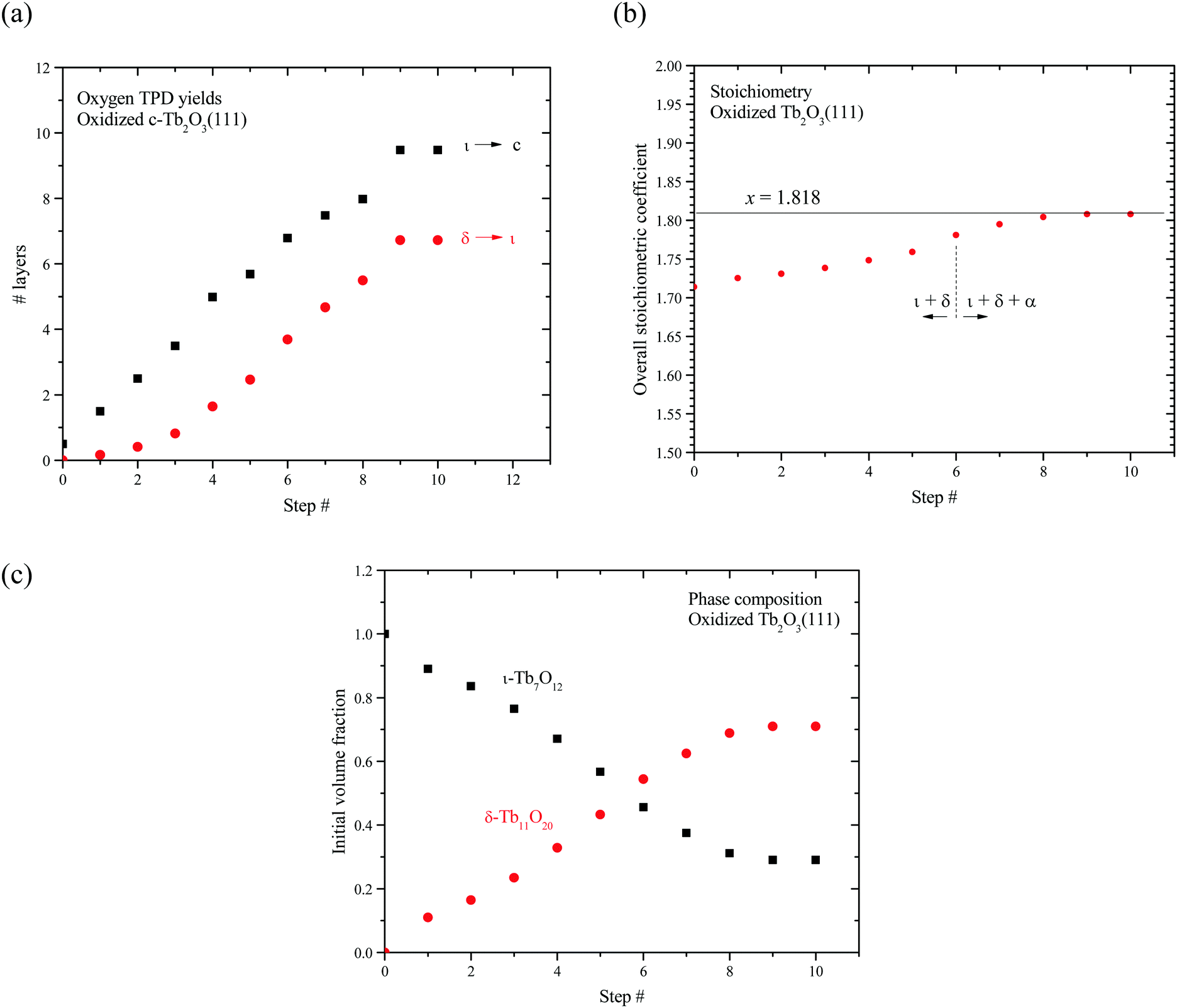 | ||
| Fig. 7 Redox of stabilized TbOx intermediates following oxidation/reduction cycles. (a) shows the net thermal reduction of δ-Tb11O20 to ι-Tb7O12 and ι-Tb7O12 to c-Tb2O3 in terms of stabilized trilayer yield, (b) shows the overall oxidized stoichiometry per transformation cycle, and (c) shows the net fraction of stabilized δ-Tb11O20 to ι-Tb7O12 within oxidized portions of the film per transformation cycle. | ||
We thus conclude that oxidation and subsequent heating during TPD generates an oxidized region of the film that initially contains Lι layers of pure ι-Tb7O12. Continued oxidation begins to transform ι-Tb7O12 to δ-Tb11O20, but an oxygen-rich α-TbOx phase starts to form before the ι → δ reaction reaches completion. Formation of the α-TbOx phase may involve oxidation of the ι or δ-phase or both. Incomplete transformation of the ι to δ-phase at the onset of α-phase formation suggests that kinetic factors begin to hinder vacancy-ordering during δ-phase formation once the oxygen content of the film becomes sufficiently high. We illustrate the proposed oxide phase development in a schematic shown in Fig. 8.
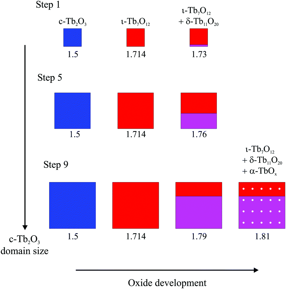 | ||
| Fig. 8 Illustration of the proposed oxide development that occurs during oxidation of the c-Tb2O3 phase as the characteristic domain size increases during successive redox steps. The illustration shows a c-Tb2O3 domain and represents the development of this generic domain during oxidation with subsequent heating in Steps 1, 5 and 9. The illustration scales the oxide domain sizes in proportion to the estimates determined from the TPD data. The oxidation treatment was the same for each step (∼60 ML O-atom exposure, 300 K). The average stoichiometric coefficient (x) is given underneath each image and the oxide phases are color coded as follows: c-Tb2O3 (blue), ι-Tb7O12 (red), δ-Tb11O20 (magenta), α-TbOx (white spots). | ||
We also estimated the average oxygen content as well as the initial volume fractions of the ι and δ phases in the oxidized c-Tb2O3 region. Our analysis assumes that the total number of layers of c-Tb2O3 that oxidizes (L) is equal to the number of layers of ι-phase that decomposes during TPD, i.e., L = Lι. Under this assumption, the initial volume fractions occupied by the ι and δ-phases are given by fι = (Lι − Lδ)/Lι and fδ = Lδ/Lι where we define these “initial” fractions as representing the phase composition immediately before α-phase formation. We further define an average oxygen concentration per layer of the entire oxidized c-Tb2O3 region as [O]avg = ([O]ι + [O]δ + [O]α)/L, and express this quantity in terms of an average stoichiometric coefficient for TbOx as x = 1.5 + [O]avg. This definition assumes that the δ and α phases form only within the region of the film that initially oxidizes to the ι-phase, which is reasonable.
Fig. 7b shows that the average stoichiometric coefficient of the oxidized c-Tb2O3 region increases from x = 1.714 to 1.808 with repeated oxidation/reduction steps. This result indicates that the rate of c-Tb2O3 oxidation increases as the total quantity of c-Tb2O3 in the film increases, with the initial and final oxygen uptake equal to 0.214 and 0.308 ML of oxygen per layer, respectively. This is an intriguing result as it suggests that c-Tb2O3 oxidation becomes increasingly facile as the average c-Tb2O3 domain size increases. We marked the sixth step in Fig. 7b to illustrate that the α-phase begins to form at an average stoichiometric coefficient of x = 1.78, i.e., below that for complete conversion of the ι to δ-phase. We estimate that 6.8 layers of the ι-phase are present at the sixth step, and find that 0.38 ML of oxygen desorbs in the δ TPD feature. This TPD yield is 0.32 ML less than the amount of oxygen that would desorb in the δ TPD feature if the ι → δ conversion reached completion, and well below the uncertainty in the O2 TPD yields, thus supporting the conclusion that the α-state begins to populate before the ι → δ reaction reaches completion. Our finding that the rate of oxidation increases as the quantity of c-Tb2O3 increases suggests that the relation between the total oxygen uptake and the redox step should exhibit an increasing slope (i.e., concave upward), provided that the amount of c-Tb2O3 in the film increases by a constant amount during each reduction step. However, a change in the slope is too gradual to resolve in our data, and lies within the variation in the total amount by which the c-Tb2O3 increases in each step (1 ± 0.3 layers per step).
Fig. 7c shows that the initial volume fraction of the ι-phase decreases steadily from 100% to 30% with successive redox steps, while the initial volume fraction of the δ-phase concurrently increases, reaching 70% at the ninth step. This result shows that an increasing quantity of the ι-phase oxidizes to the δ-phase as the quantity of c-Tb2O3 in the film increases and the CF to bixbyite transformation approaches completion. We speculate that vacancy-ordering associated with the ι → δ conversion is more facile for larger domains of the crystalline ι-phase. As a result, the extent of oxidation and the δ-phase volume fraction increase as the c-Tb2O3 domains grow in size during the repeated oxidation/reduction treatment.
Fig. 8 provides a representative schematic illustrating how the oxide phases develop during oxidation and subsequent heating of the c-Tb2O3 phase, according to our analysis, as the amount of c-Tb2O3 in the film increases in successive redox steps. Fig. 8 represents these changes for Steps 1, 5 and 9, and scales the sizes of the oxide domains in proportion to the amounts determined from our analysis of TPD data. The different oxide phases are color coded and the average stoichiometric coefficient is given underneath each image in Fig. 8. Our results provide evidence that the characteristic c-Tb2O3 domain size increases after each redox step, and that the extent to which the c-Tb2O3 phase oxidizes during a fixed O-atom exposure increases with increasing domain size. Further, as mentioned above, we contend that the c-Tb2O3 phase completely transforms to the ι-Tb7O12 phase for each oxidation and heating step, whereas oxidation beyond the ι-phase stoichiometry (x = 1.714) depends on the average domain size. Our illustration depicts the δ-phase as forming at the buried interface of the ι-Tb7O12 domain. This representation of the spatial profile of the oxide phases is speculative, yet also inconsequential to the main conclusions of the present study.
Following our TPD analysis, Fig. 8 shows that complete transformation of c-Tb2O3 to ι-Tb7O12 is followed by oxidation of a small portion of the ι-phase to δ-Tb11O20 during Step 1, resulting in final volume fractions of fι = 0.90 and fδ = 0.10 and an average stoichiometric coefficient of x = 1.73. We estimate that the amount of the c-Tb2O3 phase in the film increased from 1.5 to 5.7 layers between Steps 1 and 5, and represent this change as a proportional increase in the c-Tb2O3 domain size. Fig. 8 also shows that the δ-phase occupies a larger fraction of the domain after oxidation at Step 5 compared with Step 1. Specifically, we estimate that oxidation at Step 5 produces an oxidized region with 57% ι-Tb7O12 and 43% δ-Tb11O20 (i.e., fι = 0.57, fδ = 0.43), and an average stoichiometric coefficient of x = 1.76. Finally, we show that the ι phase oxidizes to the δ-phase during Step 9, but that the ι → δ reaction ceases and the α-phase develops instead once fδ ∼ 0.70. We illustrate the α-phase in Fig. 8 as distributed between both the ι and δ phases but note that such a distribution is speculative. It is possible that the α-phase develops preferentially within either the ι or δ-phase, but we are unable to make such a distinction from the current data.
Discussion
Redox-induced structural transformation
Our results show that repeated oxidation and thermal reduction to 1000 K causes an oxygen-deficient CF-Tb2O3 film to transform to the well-ordered c-Tb2O3 structure. The addition and removal of lattice oxygen plays a decisive role in facilitating this transformation given that annealing the CF-Tb2O3 film to 1000 K is insufficient to reorder the existing Tb–O bonds and achieve the long-range vacancy ordering that characterizes the bixbyite structure.16 The continual increase in lattice oxygen accommodated by the film over the course of the transformation is consistent with an increasing quantity of c-Tb2O3 domains within the film as well as more facile oxidation of c-Tb2O3 to ι-Tb7O12 and δ-Tb11O20. This observation suggests a mechanism in which c-Tb2O3 seeds form within the near surface region of the CF-TbOx film and continue to propagate across the buried c-Tb2O3/CF-Tb2O3 interface, particularly during thermal reduction between 900–1000 K. The similarity in the amount of oxygen desorbed and the amount of CF-Tb2O3 converted to c-Tb2O3 between ∼900–1000 K suggests that oxygen removal in this temperature regime is particularly effective in promoting the CF-Tb2O3 to c-Tb2O3 transformation.While determining the exact mechanism for the redox-induced conversion of CF to bixbyite Tb2O3 is challenging, we speculate that the avoidance of low Tb oxidation states (<+3) is important in facilitating the CF-to-bixbyite transformation via the redox mechanism compared with vacancy reordering in CF-Tb2O3. We illustrate this general idea using a hypothetical structure of a TbO6 moiety located at the CF-Tb2O3/c-Tb2O3 interface (Fig. 9a), and represent the CF-Tb2O3 to c-Tb2O3 transformation as a change in the O-vacancy site located in the initial CF-Tb2O3 side of the interface. In this model, a direct structural rearrangement involves the hopping of an O-vacancy between sites on the CF-Tb2O3 side of the interface, transforming the moiety to bixbyite. This process causes neighboring Tb cations to become reduced to the nominal +2.5 oxidation state and should thus be energetically demanding given the high stability of Tb3+vs. Tb2+.18,57 In the redox-induced mechanism, an O-atom enters the vacancy on the CF-side of the interface, and an O-atom subsequently vacates a different, nearby site to transform the entire moiety to c-Tb2O3 (Fig. 9b and c). The Tb oxidation state nominally changes from +3.5 to +3 during the reduction step depicted in Fig. 9, and thereby avoids reduction below the +3 state. An analogous mechanism is that O-atoms sequentially fill a vacancy on the c-Tb2O3 side and then the CF-Tb2O3 side to generate a TbO2 moiety, and that O-atoms vacate the apical sites shown in Fig. 9 during reduction and convert the entire moiety to c-Tb2O3. We assert that preservation of the Tb3+/Tb4+ oxidation states during the redox-mechanism is significant in lowering the energetic requirements for vacancy reordering and formation of c-Tb2O3.
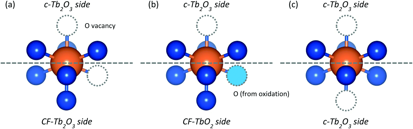 | ||
| Fig. 9 Hypothetical Tb3+ cation (a) at the edge of the c-TbOx/CF-TbOx interface, (b) after oxidation, and (c) after thermal reduction leading to advancement of the c-Tb2O3 interface. | ||
The high temperatures (>∼900 K) needed to promote the redox-mechanism for c-Tb2O3 formation are likely associated with accommodation of O-atoms into the terbia lattice after the oxidation step. The O-atoms added to the lattice are unlikely to fully relax into optimal bonding configurations at the low oxidation temperature employed (300 K). As a result, the added O-atoms are less stable than the original lattice O-atoms and preferentially vacate their binding sites during thermal reduction, restoring the oxide to the CF-Tb2O3 structure. At higher temperatures, the lattice can more fully relax and enable the added O-atoms to achieve similar stability as the original lattice oxygen. Once the added O-atoms are stabilized, it should be favorable to remove one of the original lattice O-atoms to generate the more stable bixbyite structure. A similar transition is observed during the slow reduction of CeO2(111) with H2 at 700 K where the surface retains a high degree of homogeneity and crystallinity during the progression through the (1 × 1) fluorite CeO2, (3 × 3) partially reduced CeOx, and fully reduced (4 × 4) bixbyite Ce2O3 structures.38 We emphasize that our arguments are speculative and that future computational modeling could aid in clarifying the elementary steps and energetics associated with the redox mechanism for c-Tb2O3 formation.
Thickness of the c-Tb2O3 region
Our results provide evidence that only the top layers of the film become oxidized and transform from the CF to bixbyite structure during reduction. We specifically estimate a Tb2O3 film thickness of ∼18 layers from measurements of the Pt 4f peak attenuation, whereas our O2 TPD results indicate that about 10 layers near the vacuum–solid interface transformed to c-Tb2O3. These estimates suggest that the final reduced film consists of ∼10 layers of c-Tb2O3(111) on top of 8 layers of oxygen-deficient CF-Tb2O3(111). Experimental uncertainty in our estimates is unlikely to account for such a large difference between the thickness of the entire film and the region that oxidizes and transforms to bixbyite. For example, the IMFP of Pt 4f photoelectrons needs to be lowered to ∼55% of the estimated value (15 vs. 27 Å) to predict a film thickness that equals the thickness of the oxidized region that we determine from the oxygen uptake. An error of this magnitude is physically unreasonable. Further, we estimate an uncertainty of less than 10% in the oxygen coverages determined from the O2 TPD yields. We thus conclude that the final film does in fact include a buffer region of CF-Tb2O3 separating the c-Tb2O3(111) phase from the Pt(111) substrate.We have previously reported that CF-Tb2O3(111) grows epitaxially on Pt(111) and adopts an (3 × 3)/(4 × 4) coincident structure with minimal strain due to good lattice matching between the oxide and Pt(111). In contrast, c-Tb2O3(111) has a lattice constant that is about 5.5 times larger than that of Pt(111) and would thus experience significant strain as a commensurate layer. The c-Tb2O3(111) structure can adopt a (4 × 4) structure on CF-TbOx(111). The favorable epitaxial relationship between CF-Tb2O3(111) and Pt(111) may play a key role in limiting the thickness of the c-Tb2O3(111) region that forms by repeated oxidation and reduction of the Tb2O3 film. Specifically, we assert that only the top layers of the CF-Tb2O3 film transform to c-Tb2O3 in order to maintain a region of CF-Tb2O3 between the c-Tb2O3 phase and the Pt(111) substrate that acts to mitigate strain in the oxide film.
Summary
We used O2 TPD and LEED to investigate the transformation of a Tb2O3(111) thin film from the cubic fluorite to bixbyite structure, as induced by repeated oxidation at 300 K and thermal reduction by heating to 1000 K. The CF to c-Tb2O3 conversion occurs in a stepwise fashion and discontinues after the formation of ∼10 layers of c-Tb2O3(111) at the surface for the conditions studied. Our results suggest that the final reduced film consists of a region of c-Tb2O3(111) that is separated from the Pt(111) substrate by about eight layers of CF-Tb2O3(111). We show that oxidation of the c-Tb2O3(111) phase occurs through successive formation of the ι-Tb7O12 and δ-Tb11O20 phases, and a variable-density α-TbOx phase with high oxygen content (x >∼1.8). The total oxygen uptake increases as the quantity of c-Tb2O3 increases, demonstrating that the c-Tb2O3 phase oxidizes more efficiently than the oxygen-deficient CF-Tb2O3 phase. Our results provide evidence that the CF to bixbyite transformation occurs mainly above ∼900 K as the oxidized TbOx film undergoes thermal reduction. We suggest that c-Tb2O3 regions form at phase interfaces during TbOx reduction, with this process enabling newly formed c-Tb2O3 to advance deeper into the film.Conflicts of interest
There are no conflicts to declare.Acknowledgements
We thank Sangmyeon Lee, Ankit Gokhale, and Mohammed Shariff for assistance with experiments. We gratefully acknowledge financial support for this work provided by the National Science Foundation, Division of Chemistry through grant number 1464765.References
- S. Colussi, C. de Leitenburg, G. Dolcetti and A. Trovarelli, J. Alloys Compd., 2004, 374, 387–392 CrossRef CAS.
- A. Schaefer, W. Cartas, R. Rai, M. Shipilin, L. R. Merte, E. Lundgren and J. F. Weaver, J. Phys. Chem. C, 2016, 120, 28617–28629 CrossRef CAS.
- J. Graciani, K. Mudiyanselage, F. Xu, A. E. Baber, J. Evans, S. D. Senanayake, D. J. Stacchiola, P. Liu, J. Hrbek, J. F. Sanz and J. A. Rodriguez, Science, 2014, 345, 546–550 CrossRef CAS PubMed.
- G. Vile, B. Bridier, J. Wichert and J. Perez-Ramirez, Angew. Chem., Int. Ed., 2012, 51, 8620–8623 CrossRef CAS PubMed.
- J.-H. Jhang, A. Schaefer, V. Zielasek, J. Weaver and M. Bäumer, Materials, 2015, 8, 6228–6256 CrossRef CAS PubMed.
- A. G. Dedov, A. S. Loktev, I. I. Moiseev, A. Aboukais, J. F. Lamonier and I. N. Filimonov, Appl. Catal., A, 2003, 245, 209–220 CrossRef CAS.
- O. Forlani and S. Rossini, Mater. Chem. Phys., 1992, 31, 155–158 CrossRef CAS.
- T. W. Elkins and H. E. Hagelin-Weaver, Appl. Catal., A, 2013, 454, 100–114 CrossRef CAS.
- T. W. Elkins, B. Neumann, M. Bäumer and H. E. Hagelin-Weaver, ACS Catal., 2014, 4, 1972–1990 CrossRef CAS.
- T. W. Elkins, S. J. Roberts and H. E. Hagelin-Weaver, Appl. Catal., A, 2016, 528, 175–190 CrossRef CAS.
- S. H. Overbury, D. R. Mullins, D. R. Huntley and L. Kundakovic, J. Catal., 1999, 186, 296–309 CrossRef CAS.
- R. M. Ferrizz, T. Egami, G. S. Wong and J. M. Vohs, Surf. Sci., 2001, 476, 9–21 CrossRef CAS.
- Z. Yang, T. K. Woo and K. Hermansson, Surf. Sci., 2006, 600, 4953–4960 CrossRef CAS.
- J.-H. Jhang, A. Schaefer, W. Cartas, S. Epuri, M. Bäumer and J. F. Weaver, J. Phys. Chem. C, 2013, 117, 21396–21406 CrossRef CAS.
- W. Cartas, R. Rai, A. Sathe, A. Schaefer and J. F. Weaver, J. Phys. Chem. C, 2014, 118, 20916–20926 CrossRef CAS.
- C. Lee, V. Mehar and J. F. Weaver, J. Phys. Chem. C, 2018, 122, 9997–10005 CrossRef CAS.
- A. Schaefer, B. Hagman, J. Höcker, U. Hejral, J. I. Flege and J. Gustafson, Phys. Chem. Chem. Phys., 2018, 20, 19447–19457 RSC.
- G.-y. Adachi and N. Imanaka, Chem. Rev., 1998, 98, 1479–1514 CrossRef CAS PubMed.
- J. Höcker, T. Duchoň, K. Veltruská, V. Matolín, J. Falta, S. D. Senanayake and J. I. Flege, J. Phys. Chem. C, 2016, 120, 4895–4901 CrossRef.
- T. Duchoň, J. Hackl, J. Höcker, K. Veltruská, V. Matolín, J. Falta, S. Cramm, S. Nemšák, C. Schneider, J. Flege and S. Senanayake, Ultramicroscopy, 2017, 183, 84–88 CrossRef PubMed.
- Y. Takasu, T. Yoko-o, M. Matsui, Y. Matsuda and I. Toyoshima, J. Catal., 1982, 77, 485–490 CrossRef CAS.
- A. Trovarelli, Catal. Rev., 1996, 38, 439–520 CrossRef CAS.
- D. R. Mullins, Surf. Sci. Rep., 2015, 70, 42–85 CrossRef CAS.
- G. V. Antoshin, K. M. Minachev and R. V. Dmitriev, Bulletin of the Academy of Sciences of the USSR, Division of Chemical Science, 1967, 16, 1793–1795 CrossRef.
- P. Kunzmann and L. Eyring, J. Solid State Chem., 1975, 14, 229–237 CrossRef CAS.
- V. Matolín, J. Libra, I. Matolínová, V. Nehasil, L. Sedláček and F. Šutara, Appl. Surf. Sci., 2007, 254, 153–155 CrossRef.
- P. Luches, F. Pagliuca and S. Valeri, J. Phys. Chem. C, 2011, 115, 10718–10726 CrossRef CAS.
- S. Eck, C. Castellarin-Cudia, S. Surnev, M. G. Ramsey and F. P. Netzer, Surf. Sci., 2002, 520, 173–185 CrossRef CAS.
- D. C. Grinter, R. Ithnin, C. L. Pang and G. Thornton, J. Phys. Chem. C, 2010, 114, 17036–17041 CrossRef CAS.
- L. H. Chan and J. Yuhara, J. Chem. Phys., 2015, 143, 074708 CrossRef PubMed.
- M. Alexandrou and R. M. Nix, Surf. Sci., 1994, 321, 47–57 CrossRef CAS.
- F. Faisal, A. Toghan, I. Khalakhan, M. Vorokhta, V. Matolin and J. Libuda, Appl. Surf. Sci., 2015, 350, 142–148 CrossRef CAS.
- D. R. Mullins, S. D. Senanayake and T. L. Chen, J. Phys. Chem. C, 2010, 114, 17112–17119 CrossRef CAS.
- J. Höcker, J.-O. Krisponeit, T. Schmidt, J. Falta and J. I. Flege, Nanoscale, 2017, 9, 9352–9358 RSC.
- V. Stetsovych, F. Pagliuca, F. Dvorak, T. Duchon, M. Vorokhta, M. Aulicka, J. Lachnitt, S. Schernich, I. Matolinova, K. Veltruska, T. Skala, D. Mazur, J. Myslivecek, J. Libuda and V. Matolin, J. Phys. Chem. Lett., 2013, 4, 866–871 CrossRef CAS PubMed.
- T. Duchoň, F. Dvořák, M. Aulická, V. Stetsovych, M. Vorokhta, D. Mazur, K. Veltruská, T. Skála, J. Mysliveček, I. Matolínová and V. Matolín, J. Phys. Chem. C, 2014, 118, 357–365 CrossRef.
- P. Luches, G. Gasperi, M. Sauerbrey, S. Valeri, J. Falta and J. I. Flege, Front. Chem., 2019, 7, 57 CrossRef CAS PubMed.
- J. Höcker, T. O. Menteş, A. Sala, A. Locatelli, T. Schmidt, J. Falta, S. D. Senanayake and J. I. Flege, Adv. Mater. Interfaces, 2015, 2, 1500314 CrossRef.
- T. Weisemoeller, F. Bertram, S. Gevers, A. Greuling, C. Deiter, H. Tobergte, M. Neumann, J. Wollschläger, A. Giussani and T. Schroeder, J. Appl. Phys., 2009, 105, 124108 CrossRef.
- H. Wilkens, S. Gevers, S. Röhe, A. Schaefer, M. Bäumer, M. H. Zoellner, T. Schroeder and J. Wollschläger, J. Phys. Chem. C, 2014, 118, 3056–3061 CrossRef CAS.
- T. Schroeder, P. Zaumseil, G. Weidner, C. Wenger, J. Dabrowski, H.-J. Müssig and P. Storck, J. Appl. Phys., 2006, 99, 014101 CrossRef.
- T. Weisemoeller, C. Deiter, F. Bertram, S. Gevers, A. Giussani, P. Zaumseil, T. Schroeder and J. Wollschläger, Appl. Phys. Lett., 2008, 93, 032905 CrossRef.
- A. Schaefer, S. Gevers, V. Zielasek, T. Schroeder, J. Falta, J. Wollschlager and M. Baumer, J. Chem. Phys., 2011, 134, 054701 CrossRef CAS PubMed.
- H. H. Kan, R. B. Shumbera and J. F. Weaver, J. Chem. Phys., 2007, 126, 134704 CrossRef PubMed.
- R. Bradley Shumbera, H. H. Kan and J. F. Weaver, Surf. Sci., 2007, 601, 4809–4816 CrossRef CAS.
- A. L. Gerrard, J.-J. Chen and J. F. Weaver, J. Phys. Chem. B, 2005, 109, 8017–8028 CrossRef CAS PubMed.
- J. Höcker, W. Cartas, A. Schaefer, M. Bäumer, J. F. Weaver, J. Falta and J. I. Flege, J. Phys. Chem. C, 2015, 119, 14175–14184 CrossRef.
- W. Xiao, Q. Guo and E. G. Wang, Chem. Phys. Lett., 2003, 368, 527–531 CrossRef CAS.
- C. J. Powell and A. Jablonski, NIST Electron Inelastic-Mean-Free-Path Database, National Institute of Standards and Technology, Gaithersburg, Maryland, 2010 Search PubMed.
- K. Otsuka and T. Nakajima, J. Catal., 1987, 103, 216–219 CrossRef CAS.
- S. Bernal, J. J. Calvino, G. Cifredo, J. Gatica, C. Larese and J. M. Pintado, J. Alloys Compd., 1995, 225, 633–637 CrossRef CAS.
- H. Wilkens, O. Schuckmann, R. Oelke, S. Gevers, A. Schaefer, M. Bäumer, M. H. Zoellner, T. Schroeder and J. Wollschläger, Appl. Phys. Lett., 2013, 102, 111602 CrossRef.
- R. Olbrich, G. E. Murgida, V. Ferrari, C. Barth, A. M. Llois, M. Reichling and M. V. Ganduglia-Pirovano, J. Phys. Chem. C, 2017, 121, 6844–6851 CrossRef CAS.
- G. Gasperi, L. Amidani, F. Benedetti, F. Boscherini, P. Glatzel, S. Valeri and P. Luches, Phys. Chem. Chem. Phys., 2016, 18, 20511–20517 RSC.
- H. Inaba, A. Navrotsky and L. Eyring, J. Solid State Chem., 1981, 37, 77–84 CrossRef CAS.
- L. Eyring, in Synthesis of Lanthanide and Actinide Compounds, ed. G. Meyer and L. R. Morss, Springer, Netherlands, Dordrecht, 1991, pp. 187–224 Search PubMed.
- J. M. Leger, N. Yacoubi and J. Loriers, J. Solid State Chem., 1981, 36, 261–270 CrossRef CAS.
Footnote |
| † Electronic supplementary information (ESI) available: O2 TPD data obtained after the CF to bixbyite transformation; estimates of oxide-phase quantities from O2 TPD fits. See DOI: 10.1039/c9cp05083c |
| This journal is © the Owner Societies 2020 |