Template-free fabrication of single-crystalline calcite nanorings during crystal growth in water†
Yuki
Kezuka
 *,
Maya
Yoshida
and
Masahiko
Tajika
Shiraishi Central Laboratories Co. Ltd., 4-78, Amagasaki, Hyogo 660-0085, Japan. E-mail: kezuka_yuki@shiraishi.co.jp
First published on 8th November 2019
Abstract
Morphology evolution of calcite nanoparticles was investigated in detail during crystal growth induced by containing their aqueous slurry at a temperature of 95 °C. Formation of a single-crystalline nanoring that has a single cavity was confirmed soon after the slurry temperature was elevated to 95 °C. No templates were employed during the crystal growth process.
Nanomaterials, whose size ranges between 1 and 100 nm, have many important applications such as filler materials and catalysts, and in photonics and biotechnologies.1,2 Since most chemical and physical properties of nanoparticles strongly depend on their shapes and sizes, controlling their primary particle morphologies is technologically relevant.1,3 In addition, many studies have demonstrated that several properties of nanocomposites can be tuned by choosing filler nanoparticles that have appropriate shapes/sizes.4 These are called the nano-effects in the pigment-extender industry and cannot be accomplished by non-nanoscale particles.
Recently, formation of hollow nanoparticles or nanorings (ring-like nanoparticles) is attracting much attention because of their unique electrical,5 magnetic,6 and optical7,8 properties and their potential applications for lightweight filler materials, efficient catalysis,8 sensors,7 energy storage,9 and biomedicine.10 There are several reports which demonstrated the fabrication of single-crystalline nanorings made of metal,11 semiconductors,12,13 and oxides.10,14 In many cases, nanoring fabrications use the precipitation of ring-like structures onto templates followed by template removal. Other techniques utilize the oriented attachment15 of smaller nanocrystals12 or the nanoscale Kirkendall effect.16 However, there is no report which has utilized these techniques for carbonate nanoparticles. Calcite micron-sized hollow particles have been fabricated by using double-hydrophilic block copolymers as templates for precipitation.17 Moreover, a single-crystalline calcite ring-like particle with a cavity has been precipitated using Langmuir monolayers of an amphiphilic porphyrin at the air/water interface as templates.18 Calcite hopper-like crystals (rhombohedron with face-centred defects in all six {104} faces) have been produced by introducing CO2 gas into aqueous calcium chloride−alcohol solutions without using any templates for precipitation.19,20 However, all the resulting particles were not nanoscale in size (∼30 μm). In this communication, a new template-free way to fabricate nanorings made of carbonates is reported.
Calcium carbonate (CaCO3) is very abundant in nature and is present in natural rocks (e.g., limestone, chalk, marble, and calcite rock) and biominerals (e.g., shells, pearls, corals, and exoskeletons). Calcium carbonate has three anhydrous polymorphs, i.e., calcite, aragonite, and vaterite. Of these, calcite is the most common thermodynamically stable phase under ambient conditions.21 Calcite nanoparticles are used as fillers in a wide range of materials including paper, plastics, adhesive/sealants, and rubber.22 The incorporation of calcite nanoparticles enhances the light reflection and opacity of white paper,23 improves the impact toughness of plastics,24 controls the viscosity and thixotropy of adhesive/sealants, and increases the tensile strength of rubber.22 Because of their relevance to these various engineering applications and understanding of the mineralization process in nature, controlling the primary particle morphology of calcium carbonate nanoparticles has been studied extensively, including morphologies of calcite single crystalline nanorods/wires/needles,25,26 nanobacteria-like crystals,27 chain-like nanoparticles,28–30 aragonite nanorods,26 hollow vaterite nanospheres,31 and amorphous calcium carbonate nanospheres.32 The industrial application of calcium carbonate nanoparticles can be further broadened by additional engineered morphologies; however, the fabrication of calcite nanorings has not been reported yet.
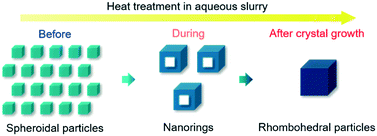
In the present study, an aqueous slurry of calcite nanoparticles (size: ∼30 nm) was heated from room temperature (RT) to 95 °C and kept at this temperature for 6 h; the particle morphology evolution was carefully monitored during the heat treatment, mainly by Brunauer–Emmett–Teller (BET)-specific surface area (SSA) measurement, X-ray diffraction (XRD), transmission electron microscopy (TEM), and scanning electron microscopy (SEM). At RT, spheroidal particles were mainly observed in the slurry. Soon after the slurry temperature was elevated to 95 °C, the formation of calcite nanorings (size: ∼60 nm) was confirmed. These nanorings were surprisingly single-crystalline. Finally, after 6 h at 95 °C, the formation of rhombohedral particles (size: ∼80 nm), unifaceted with {104} faces, was confirmed (Fig. 1). To our knowledge, this is the first study to demonstrate the fabrication of a single-crystalline calcite nanoring that has a single cavity.
 | ||
| Fig. 1 Schematic illustration of the calcite nanoparticle morphology evolution during its crystal growth induced by containing its aqueous slurry at 95 °C. | ||
Calcite nanoparticles were synthesized by the CO2 gas bubbling method, introducing CO2 gas into calcium hydroxide (Ca(OH)2) aqueous slurry.33 Detailed synthesis procedures are given in previous reports.29,30 The solid content of the resulting slurry of calcite nanoparticles was then adjusted to 10.0 wt% by dilution and agitation, and kept at 25 °C. The slurry was then heated to a treatment temperature of 95 °C at a heating rate of ∼12 °C min−1, which corresponds to an approximate energy expenditure rate of ∼45 kJ min−1 for 1 kg of the aqueous slurry, in order to induce crystal growth for calcite nanoparticles. The slurry was mechanically stirred during the heat treatment and kept at 95 °C for 6 h. The slurry was sampled several times during the aging process for structural characterization. The sampled suspensions were immediately washed with sufficient amounts of acetone to stop the crystal growth, vacuum filtered, and then dried to powder form. The specimens for TEM observation were prepared by dispersing the obtained powders in isopropyl alcohol, dropping the suspension on carbon/collodion-coated copper grids, removing the excess liquid, and vacuum-drying.
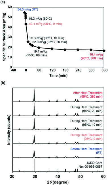
Fig. 2a shows the changes in the BET-SSA of the calcite nanoparticles sampled during the heat treatment. In the graph, the moment when the slurry temperature reached 95 °C was defined as 0 min. The BET-SSA rapidly decreased after only 10 min at the slurry temperature of 95 °C. After that, the BET-SSA gradually decreased, levelling out at 16.4 m2 g−1 after 6 h at 95 °C. The decrease in the BET-SSA probably suggests the crystal growth of the calcite nanoparticles induced by the heat treatment of the aqueous slurry.
Fig. 2b shows the powder XRD patterns of the samples before/during/after the 6 h heat treatment plus the standard reflections for the calcite crystal structure (ICDD card no. 00-066-0867). All the peaks were attributed to the calcite structure, and no impurity phases or other calcium carbonate phases were observed. Moreover, sharpening of each peak can be observed in the XRD patterns with increasing heat treatment time. The average crystallite sizes calculated by Scherrer's equation34 using the calcite {104} diffraction peak at ∼29.5° were 31, 38, 63, 69, and 81 nm for calcite crystals sampled before the heat treatment and at 0, 10, 20, and 360 min after the slurry temperature reached 95 °C. The decrease in the BET-SSA during the heat treatment (Fig. 2a) must be derived mainly from the increase in the average crystallite size.
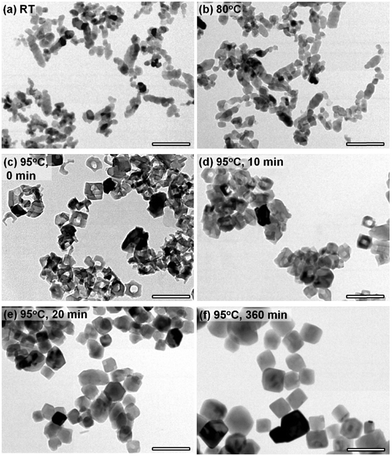
In order to investigate particle morphology evolutions during the crystallite growth, TEM observations were performed (Fig. 3). Before starting the heat treatment, mainly spheroidal and a small amount of chain-like particles were observed as previously reported (Fig. 3a).28 The approximate primary particle size of the spheroidal particles was observed to be 30 nm, which reasonably corresponds to the average crystallite size determined from the XRD data. When the slurry temperature reached 80 °C, significant changes in the particle morphology were not observed (Fig. 3b), although the BET-SSA slightly decreased (Fig. 2a). Surprisingly, only about 2 min after this, when the slurry temperature reached 95 °C, the formation of frame-like nanorings was observed (Fig. 3c). The exterior size of nanorings was ∼60 nm. The presence of spheroidal and chain-like particles was no longer observed. The BET-SSA, nevertheless, decreased monotonically with the fragmentation of chain-like particles into spheroidal particles and the formation of nanorings with cavities, because of the rapid increase in crystallite sizes. The average crystallite size of the nanorings calculated from the XRD pattern (Fig. 2b) (∼38 nm) was considerably smaller than the exterior size of nanorings observed by TEM (∼60 nm). This must be mainly due to the presence of nanoring cavities and probably partially due to the lower crystallinity of nanorings. At 10 min after the slurry temperature reached 95 °C, most of the particles still have a hollow shape (Fig. 3d). The particles had rhombohedral shapes as the particles develop facetted surfaces. After 20 min, the presence of nanorings was no longer observed (Fig. 3e). From that point, the crystals simply grew according to the classical Ostwald ripening process,35 where larger particles become larger at the expense of smaller particles. At 360 min (6 h), all the crystals were stable and had rhombohedral shapes with flat crystal surfaces (Fig. 3f). Other than the crystals obtained soon after the slurry temperature reached 95 °C, the average crystallite sizes calculated from the XRD data better corresponded to the primary particle sizes observed by TEM.
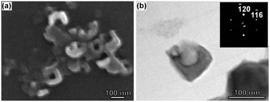
Fig. 4(a) shows the field-emission (FE)-SEM image of calcite nanorings. Observing with a more surface sensitive method than TEM, the surface morphology of the nanorings with single cavities can be clearly confirmed. Fig. 4(b) shows the BF-TEM image for a nanoring and the corresponding selected area electron diffraction (SAED) pattern. The nanoring was considered single crystalline based on the absence of spot splitting in the SAED pattern. The inner faces were almost parallel to the external faces, as if a negative crystal was formed in the particle.
 | ||
| Fig. 4 (a) FE-SEM image of calcite nanorings. (b) BF-TEM image of a nanoring. The inset in (b) shows the SAED pattern taken from a region including the nanoring. | ||
Sand et al. fabricated calcite hopper-like crystals (∼30 μm) in water–alcohol mixtures.20 They interpreted from their SEM investigations that the cavities on the crystal surface are remnant molds for dissolved aragonite clusters that previously attached intimately on the calcite particle surface. The resulting particle morphologies were considerably similar to the nanorings fabricated in the present study; however, this cannot be a formation mechanism for nanorings fabricated in the present study, because the existence of aragonite or any other phase was not confirmed by either XRD or TEM investigations. On the other hand, spirally terraced etch pit formation around screw dislocation cores at the crystal surface is a known phenomenon during the dissolution process of bulk crystals and micron-sized particles.36 According to Frank's theory,37 these pits can be formed in aqueous systems during a dissolution process of crystals, but not during a growth process. This can be a possible explanation for the cavity formation for calcite nanorings; however, no evidence of dislocation was observed by the TEM investigations in the present study. In this study, the crystal growth behaviour between the slurry temperatures of 80 °C and 95 °C could not be monitored, because the growth was too fast. Nanorings are considered to form during the kinetic dissolution process of nanoparticles that have a size of ∼60 nm. Moreover, some fraction of C-shaped particles was observed both by TEM (Fig. 3c) and SEM (Fig. 4a). These particles are believed to form during the dissolution of nanorings.
Soon after the slurry temperature reached 95 °C, the saturation index (SI) of calcite is high and nanorings were observed during the kinetic dissolution process. At about 20 min, the SI decreased and the formation of nanorings was no longer observed. The average crystallite size continues to increase with time; however, it seems that dissolution of particles occurs not from the centre of the particle faces but from the particle edges under low SI conditions. And, finally after 6 h, all the particles had rhombohedral morphologies with flat particle faces.
In summary, the template-free fabrication of single-crystalline calcite nanorings was demonstrated using crystal growth in an aqueous system. Calcite spheroidal nanoparticles (∼30 nm) were synthesized via the CO2 gas bubbling method, and the resulting aqueous slurry was kept at 95 °C. Soon after the slurry temperature reached 95 °C, the formation of single-crystalline nanorings (∼60 nm) was confirmed. Finally, after holding at 95 °C for 6 h, the formation of rhombohedral particles (∼80 nm) was confirmed. The findings of the present study are important not only for the potential application of the nanorings in industry, but also for understanding the mineralization process in nature. Future studies are needed to fully understand the formation mechanism for nanorings and to establish optimum heat treatment conditions for enhancing their formation. Time-resolved investigations such as in situ TEM observations are considered critical to enhancing the understanding of calcite nanoring formation.
Conflicts of interest
There are no conflicts to declare.Acknowledgements
We thank Prof. Yuichi Ikuhara and Dr. Eita Tochigi (Institute of Engineering Innovation, The University of Tokyo) for fruitful discussions.References
- W. J. Stark, P. R. Stoessel, W. Wohlleben and A. Hafner, Chem. Soc. Rev., 2015, 44, 5793 RSC.
- O. L. Muskens, S. L. Diedenhofen, B. C. Kaas, R. E. Algra, E. P. A. M. Bakkers, J. G. Rivas and A. Lagendijk, Nano Lett., 2009, 9, 930 CrossRef CAS.
- S. Mann and G. A. Ozin, Nature, 1996, 382, 313 CrossRef CAS; F. C. Meldrum and H. Cölfen, Chem. Rev., 2008, 108, 4332 CrossRef PubMed.
- M. Avella, S. Cosco, M. L. Di Lorenzo, E. Di Pace and M. E. Errico, J. Therm. Anal. Calorim., 2005, 80, 131 CrossRef CAS; M. Avella, S. Cosco, M. L. Di Lorenzo, E. Di Pace, M. E. Errico and G. Gentile, Eur. Polym. J., 2006, 42, 1548 CrossRef; E. L. Cussler, S. E. Hughes, W. J. Ward and R. Aris, J. Membr. Sci., 1988, 38, 161 CrossRef.
- K. A. Matveev, A. I. Larkin and L. I. Glazman, Phys. Rev. Lett., 2002, 89, 096802 CrossRef CAS.
- J. Rothman, M. Kläui, L. Lopez-Diaz, C. A. F. Vaz, A. Bleloch, J. A. C. Bland, Z. Cui and R. Speaks, Phys. Rev. Lett., 2001, 86, 1098 CrossRef CAS; H.-M. Fan, J.-B. Yi, Y. Yang, K.-W. Kho, H.-R. Tan, Z.-X. Shen, J. Ding, X.-W. Sun, M. C. Olivo and Y.-P. Feng, ACS Nano, 2009, 3, 2798 CrossRef PubMed.
- J. Aizpurua, P. Hanarp, D. S. Sutherland, M. Käll, G. W. Bryant and F. J. G. de Abajo, Phys. Rev. Lett., 2003, 90, 057401 CrossRef CAS PubMed.
- P. Hu, S. S. Pramana, S. Cao, C. K. Ngaw, J. Lin, S. C. J. Loo and T. T. Y. Tan, Adv. Mater., 2013, 25, 2567 CrossRef CAS PubMed.
- X. W. Lou, Y. Wang, C. L. Yuan, J. Y. Lee and L. A. Archer, Adv. Mater., 2006, 18, 2325 CrossRef CAS.
- H.-M. Fan, J.-B. Yi, Y. Yang, K.-W. Kho, H.-R. Tan, Z.-X. Shen, J. Ding, X.-W. Sun, M. C. Olivo and Y.-P. Feng, ACS Nano, 2009, 3, 2798 CrossRef CAS PubMed.
- L. P. Jiang, S. Xu, X. M. Zhu, J. R. Zhang, J. J. Zhu and H. Y. Chen, Inorg. Chem., 2004, 43, 5877 CrossRef CAS PubMed.
- K. S. Cho, D. V. Talapin, W. Gaschler and C. B. Murray, J. Am. Chem. Soc., 2005, 127, 7140 CrossRef CAS PubMed; B. Liu and H. C. Zeng, J. Am. Chem. Soc., 2005, 127, 18262 CrossRef PubMed.
- G.-Q. Xin, H.-P. Ding, Y.-G. Yang, S.-L. Shen, Z.-C. Xiong, X. Chen, J. Hao and H.-G. Liu, Cryst. Growth Des., 2009, 9, 2008 CrossRef CAS.
- X. Hu, J. C. Yu, J. Gong, Q. Li and G. Li, Adv. Mater., 2007, 19, 2324 CrossRef CAS; C. J. Jia, L. D. Sun, F. Luo, X. D. Han, L. J. Heyderman, Z. G. Yan, C. H. Yan, K. Zheng, Z. Zhang, M. Takano, N. Hayashi, M. Eltschka, M. Klaui, U. Rudiger, T. Kasama, L. Cervera-Gontard, R. E. Dunin-Borkowski, G. Tzvetkov and J. Raabe, J. Am. Chem. Soc., 2008, 130, 16968 CrossRef.
- F. C. Meldrum, H. Colfen and P. M. Dove, Science, 2015, 349, aaa6760 CrossRef.
- Y. Yin, R. M. Rioux, C. K. Erdonmez, S. Hughes, G. A. Somorjai and A. P. Alivisatos, Science, 2004, 304, 711 CrossRef CAS.
- H. Cölfen and M. Antonietti, Langmuir, 1998, 14, 582 CrossRef.
- J. Lahiri, G. Xu, D. M. Dabbs, N. Yao, I. A. Aksay and J. T. Groves, J. Am. Chem. Soc., 1997, 119, 5449 CrossRef CAS.
- S. R. Dickinson and K. M. McGrath, J. Mater. Chem., 2003, 13, 928 RSC.
- K. K. Sand, J. D. Rodriguez-Blanco, E. Makovicky, L. G. Benning and S. L. S. Stipp, Cryst. Growth Des., 2012, 12, 842 CrossRef CAS.
- J. C. Jamieson, J. Chem. Phys., 1953, 21, 1385 CrossRef CAS; L. N. Plummer and E. Busenberg, Geochim. Cosmochim. Acta, 1982, 46, 1011 CrossRef.
- Roskill Information Services Ltd., Ground and Precipitated Calcium Carbonate: Global Industry Markets and Outlook, Roskill Information Services Ltd., 1st edn, 2012 Search PubMed.
- A. Barhoum, H. Rahier, R. E. Abou-Zaied, M. Rehan, T. Dufour, G. Hill and A. Dufresne, ACS Appl. Mater. Interfaces, 2014, 6, 2734 CrossRef CAS.
- Y. Lin, H. Chen, C. Chan and J. Wu, Polymer, 2010, 51, 3277 CrossRef CAS.
- D. Liu and M. Z. Yates, Langmuir, 2006, 22, 5566 CrossRef CAS PubMed; Y. Y. Kim, N. B. J. Hetherington, E. H. Noel, R. Kroger, J. M. Charnock, H. K. Christenson and F. C. Meldrum, Angew. Chem., Int. Ed., 2011, 50, 12572 CrossRef; Y. Dai, H. Zou, H. Zhu, X. Zhou, Y. Song, K. Zheng, Z. Shi and Y. Sheng, CrystEngComm, 2018, 20, 496 RSC.
- Y. Kezuka, K. Kawai, K. Eguchi and M. Tajika, Minerals, 2017, 7, 133 CrossRef.
- K. Benzerara, N. Menguy, F. Guyot, C. Dominici and P. Gillet, Proc. Natl. Acad. Sci. U. S. A., 2003, 100, 7438 CrossRef CAS.
- M. Takasaki, Y. Kezuka, M. Tajika, Y. Oaki and H. Imai, ACS Omega, 2017, 2, 8997 CrossRef CAS.
- Y. Kezuka, Y. Kuma, S. Nakai, K. Matsubara and M. Tajika, Powder Technol., 2018, 335, 195 CrossRef CAS.
- Y. Kezuka, E. Tochigi, H. Murata, M. Yoshida, K. Eguchi, A. Nakahira, Y. Ikuhara and M. Tajika, Cryst. Growth Des., 2019, 19, 6784 CrossRef CAS.
- A. Cai, X. Xu, H. Pan, J. Tao, R. Liu, R. Tang and K. Cho, J. Phys. Chem. C, 2008, 112, 11324 CrossRef CAS.
- N. Koga, Y. Nakagoe and H. Tanaka, Thermochim. Acta, 1998, 318, 239 CrossRef CAS; D. Gebauer, A. Völkel and H. Cölfen, Science, 2008, 322, 1819 CrossRef.
- T. Shiraishi, U.S. Pat., 1654099 1927 Search PubMed.
- P. Scherrer, Nachr. Ges. Wiss. Goettingen, Math.-Phys. Kl., 1918, 2, 96 Search PubMed.
- W. Ostwald, Z. Phys. Chem., 1900, 34, 495 Search PubMed.
- S. Amelinckx, Philos. Mag., 1953, 44, 337 Search PubMed; J. N. Clark, J. Ihli, A. S. Schenk, Y.-Y. Kim, A. N. Kulak, J. M. Campbell, G. Nisbet, F. C. Meldrum and I. K. Robinson, Nat. Mater., 2015, 14, 780 CrossRef CAS.
- F. C. Frank, Acta Crystallogr., 1951, 4, 497 CrossRef CAS.
Footnote |
| † Electronic supplementary information (ESI) available. See DOI: 10.1039/c9ce01403a |
| This journal is © The Royal Society of Chemistry 2020 |


