
Salt nanoconfinement in zirconium-based metal–organic frameworks leads to pore-size and loading-dependent ionic conductivity enhancement†
Sorout
Shalini
 a,
Thomas P.
Vaid
a and
Adam J.
Matzger
*ab
a,
Thomas P.
Vaid
a and
Adam J.
Matzger
*ab
aDepartment of Chemistry, University of Michigan, 930 North University Avenue, Ann Arbor, MI 48109, USA. E-mail: matzger@umich.edu
bDepartment of Macromolecular Science and Engineering, University of Michigan, Ann Arbor, MI 48019, USA
First published on 1st June 2020
Abstract
The effect of nanoscale confinement of a salt on its ionic conductivity was studied for [NEt4][TFSI] melt-loaded in three isoreticular zirconium-based MOFs: UiO-66, UiO-67, and PCN-56. Conductivity of the MOF-salt composites was up to a factor of 50 higher than the pure salt, and maximized with slightly less than full loading of the MOFs.
Solid state electrolytes are of interest for lithium-ion batteries for increased safety and as an enabling technology for lithium metal anodes.1 The most common solid-state electrolytes are inorganic ionic solids such as Li7P3S11 that have vacant or interstitial Li+ ions that provide a low-energy pathway for ion movement.2 Alternatively, amorphous or glassy inorganic solids are disordered and can have the high ionic conductivity necessary for solid electrolytes.3 For normally crystalline inorganic salts, it is sometimes possible to induce disorder and enhance ionic conductivity through the formation of a composite with an insulator such as Al2O3 that disrupts the salt structure at the interfaces between the salt and Al2O3.4,5 Mesoporous alumina has porosity on the nanometer scale, and studies of LiI loaded in mesoporous alumina found ionic conductivity enhancement over pure LiI, and the largest effect was observed in the smallest pore size examined, 4.2 nm.6,7 Similar confinement of salts in a microporous host (pore diameter <2 nm) would be expected to lead to an even higher enhancement of ionic conductivity. Metal–organic frameworks (MOFs) are just such materials,8 with high porosity and crystallinity leading to well-defined pore sizes and chemical environments. There are sets of “isoreticular” MOFs that have the same metal cluster nodes and network topology with organic linkers of varying lengths, providing a set of MOFs that vary primarily in pore size. Additionally, the vast majority of MOFs are electrically insulating, an important feature of any solid electrolyte to be used in a battery.
Herein we describe a study of the electrical properties of the salt tetraethylammonium bis(trifluoromethylsulfonyl)-imide, [NEt4][TFSI] (Fig. 1a), loaded in an isoreticular series of zirconium-based MOFs. The salt [NEt4][TFSI] was used because its low melting point (102 °C) allows for loading of the salt in the molten state under solvent-free conditions such that solid-state ionic conductivity of the salt-MOF composites can be probed in the absence of competing solvent-mediated pathways.9 [NEt4][TFSI] serves as a model for other salts (LiTFSI, Mg(TFSI)2, etc.) that are of interest for solid electrolytes in metal-ion batteries, and a mixture of the ionic liquid [emim][TFSI] (emim = 1-ethyl-3-methlylimidazolium) and LiTFSI loaded in UiO-67 or MOF-525 has been reported as a lithium ion battery solid electrolyte.10,11
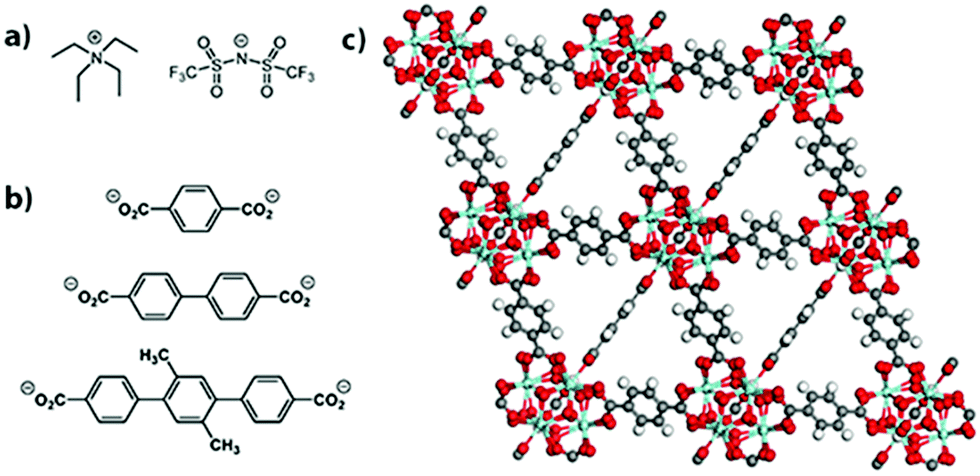 | ||
| Fig. 1 Structure of the (a) salt [NEt4][TFSI], (b) linkers for UiO-66 (top), UiO-67 (middle), and PCN-56 (bottom), and (c) UiO-66. | ||
Various MOFs and covalent organic frameworks (COFs) have been reported as components of solid ion conductors12 with intentional functionalization to make them anionic and/or include added solvent and salts.13–18 Our goal is to study the conductivity enhancement of a salt that is purely due to its spatial confinement within a MOF, with no solvent or other additives present. Many room-temperature ionic liquids (ILs) have been loaded in MOFs to make composites for a variety of applications.19–23 Some of those composites exhibited a higher ionic conductivity than the neat IL at low temperatures (where the neat IL is solid), as discussed below.24,25
The MOFs employed here are UiO-66, UiO-67, and PCN-56.26,27 Powder X-ray diffraction (PXRD) patterns matched the literature patterns, and the BET surface areas determined by N2 sorption isotherms were 1601, 2824, and 3318 m2 g−1, respectively (see ESI,† Fig. S1 and S2). They are isoreticular and all have Zr6O4(OH)4(O2CR)12 nodes. The structure of UiO-66, along with the linkers for all three MOFs, are shown in Fig. 1b and c. The increasing linker length from UiO-66 to UiO-67 to PCN-56 leads to increased pore sizes and fractional void space within the MOFs along the series (Table 1). Zirconium-based MOFs are among the most chemically stable MOFs and provide an inert porous framework in which to load the salt.
| MOF | Pore diameters (nm) | Fractional void volume | Mass% [NEt4][TFSI] theor. full loading | Mass% [NEt4][TFSI] loading achieved |
|---|---|---|---|---|
| UiO-66 | 0.8, 1.1 | 0.481 | 38.3 | 38.4 |
| UiO-67 | 1.2, 1.6 | 0.655 | 58.8 | 46.6 |
| PCN-56 | 1.6, 2.0 | 0.728 | 68.1 | 50.0 |
From the fractional void volume of each MOF, the theoretical maximum loading of [NEt4][TFSI] can be calculated, assuming the [NEt4][TFSI] loads at the same density as in a pure crystal (Table 1). Actual loadings will be lower because the salt will not pack as densely in the MOF as in a pure crystal. The maximum [NEt4][TFSI] loading in each MOF was determined by differential scanning calorimetry (DSC) and PXRD. In both cases the loading occurred when molten [NEt4][TFSI] was drawn into the activated (empty) MOF by capillary forces. The salt [NEt4][TFSI] cannot attain its crystalline structure when it is in the MOF pores—the octahedral pores of UiO-66, for example, have space for only ∼1.3 ion pairs (Table S1 in the ESI† shows the calculated capacity for both pores in each MOF). Therefore, as previously observed in related materials,9,28 the salt will not display the characteristic endothermic melting of pure [NEt4][TFSI] in the DSC trace of the composite, nor will the PXRD pattern have the peaks due to crystalline [NEt4][TFSI]. For each MOF, physical mixtures of the MOF and different mass fractions of [NEt4][TFSI] were made by grinding the two together. These mixtures were used directly for DSC experiments, and PXRD patterns were examined before and after heating the mixture above the melting point of [NEt4][TFSI].
The DSC trace of pure [NEt4][TFSI] (Fig. 2a) is similar to a published thermogram,29 showing a small endotherm due to a polymorphic phase transition at 53 °C and an endotherm due to melting at 102 °C. The multi-cycle DSCs of two different compositions of [NEt4][TFSI]-UiO-67 illustrate the difference between a composition at which the salt can fully load (38.4% [NEt4][TFSI] and 61.6% UiO-67 by mass) and one at which some salt cannot load (50.0% [NEt4][TFSI] and 50.0% UiO-67). In the DSC trace of 38.4% [NEt4][TFSI] (Fig. 2b), run through two cycles from 40 °C to 130 °C to 40 °C at 10 °C min−1, on the first cycle the endothermic polymorphic phase transition at 53 °C is observed, followed by an exotherm at 99 °C, with no melt endotherm at 102 °C. Apparently the heat released due to the adsorption of the liquid [NEt4][TFSI] in the MOF is greater than the heat required to melt the [NEt4][TFSI], and these processes happen simultaneously, slightly below the melting point of [NEt4][TFSI]. On the second cycle of the DSC, no thermal events are observed, indicating that the [NEt4][TFSI] has completely adsorbed into the pores of the UiO-67. The DSC trace of 50–50 [NEt4][TFSI]-UiO-67 mixture is shown in Fig. 2c. In this case four complete thermal cycles between 40 °C and 130 °C were run, with 5 min, 30 min, 60 min, and 24 h holds at 130 °C. In the first cycle there is an exotherm at 95 °C due to the adsorption of liquid [NEt4][TFSI] into the UiO-67. However, in contrast to 38.4 mass% [NEt4][TFSI], an exotherm due to solidification of liquid [NEt4][TFSI] is observed during the cooling portion of the first cycle at 84 °C, indicating that there is some [NEt4][TFSI] not adsorbed into the MOF. In the second and subsequent cycles, a melt endotherm is observed on the heating cycle (93 °C) and a freezing endotherm on the cooling cycle (83 °C), indicating that there remains [NEt4][TFSI] not adsorbed into the MOF. Similar experiments were performed across a range of compositions for all three of the MOFs (see ESI,† Fig. S3–S6 for DSCs (including larger versions of 2a–2c), Table S2 for loadings tested).
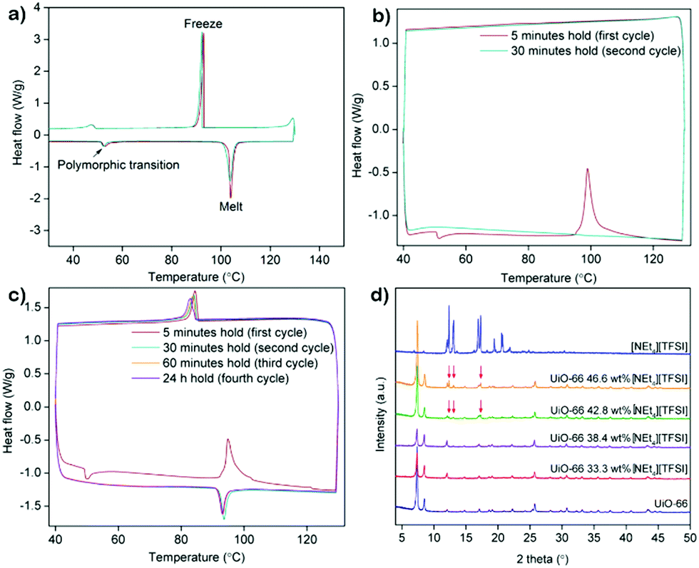 | ||
| Fig. 2 DSC traces of (a) neat [NEt4][TFSI], (b) 38.4% [NEt4][TFSI] and 61.6% UiO-67 by mass, and (c) 50.0% [NEt4][TFSI] and 50.0% UiO-67 by mass. (d) PXRD pattern of [NEt4][TFSI], UiO-66, and various mixtures of the two after heating at 130 °C for 30 min and cooling to room temperature. | ||
PXRD can be similarly used to monitor the loading of [NEt4][TFSI] in the MOFs. Fig. 2d shows the PXRD pattern of pure [NEt4][TFSI], pure UiO-66, and various mixtures of [NEt4][TFSI] and UiO-66 after heating to 130 °C for 8–16 h and cooling to room temperature. The samples with 33.3% and 38.4% [NEt4][TFSI] show diffraction peaks only from UiO-66, indicating that all of the [NEt4][TFSI] has loaded into the MOF and no crystalline [NEt4][TFSI] is present. In contrast, the PXRD patterns from the samples with 42.8% and 46.6% [NEt4][TFSI] both show diffraction peaks from [NEt4][TFSI] (in addition to the UiO-66 peaks), indicating that crystalline [NEt4][TFSI] is present that has not been adsorbed in the MOF. These results are consistent with those from DSC experiments, where 38.4% [NEt4][TFSI] was completely adsorbed in the MOF but 42.8% was not. There is agreement between the results of DSC and PXRD determinations of the completeness of loading for all three MOFs (see ESI,† Fig. S7–S9 (including larger version of Fig. 2d), Table S2 for loadings tested).
The highest mass fractions for which complete loading of [NEt4][TFSI] was achieved was 38.4% for UiO-66, 46.6% for UiO-67, and 50.0% for PCN-56, as shown in the last column of Table 1. UiO-67 and PCN-56 load to less than their theoretical values, as packing in the MOF is less efficient than in crystalline [NEt4][TFSI]. UiO-66 loads to almost exactly the theoretical value, likely due to the presence of missing-linker and missing-node defects, which means that the actual void volume is higher than the theoretical void volume.30
Electrochemical impedance spectroscopy (EIS) was used to determine the ionic conductivity of various compositions of different MOF-[NEt4][TFSI] composites as a function of temperature. One set of Nyquist plots of data recorded at temperatures from 22 °C to 90 °C for the UiO-67 composite with 42.8 mass% [NEt4][TFSI] is shown in Fig. 3a (others in the ESI,† Fig. S10–S12). Fig. 3b–d show plots of the log(conductivity) versus the mass fraction of [NEt4][TFSI] in composites with the three MOFs. For each MOF, the conductivity tends to increase as the [NEt4][TFSI] content increases, until it then decreases at the [NEt4][TFSI] mass fraction that corresponds to complete filling of each MOF (indicated by the vertical dashed blue lines in Fig. 3). The increase in conductivity as [NEt4][TFSI] content increases is due to the increasing number of charge carriers. The decrease at full capacity for each MOF is intriguing—we hypothesize that this is due to the lack of empty space within the MOFs, hindering ion movement. At less than full capacity, there are some empty voids in the MOF interior akin to vacancies in a crystalline salt, facilitating ion movement. A previous study found that a [emim][N(CN)2] (m.p. = −12 °C) composite with the zirconium-based MOF PCN-777 had higher conductivity than solid [emim][N(CN)2] (at temperatures below the m.p. of the IL), and that the room-temperature conductivity of the composite was at a maximum at ∼62% filling of the porous volume, similarly observing a maximum in conductivity at less-than-complete filling.25 Additionally, a combined experimental and computational study of the ionic conductivity of the IL [bmim][TFSI] (bmim = 1-butyl-3-methlylimidazolium) in the MOF HKUST-1 found decreased conductivity at the highest filling of the IL.31 Those simulations suggest that transport is limited at the MOF pore apertures where cations encounter anions moving in the opposite direction under the influence of the applied electric field.
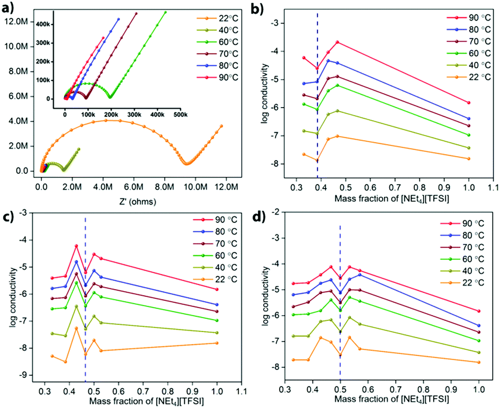 | ||
| Fig. 3 (a) Nyquist plots for the UiO-67 composite with 42.8 mass% [NEt4][TFSI] at temperatures from 22 °C to 90 °C. Plots of the log(conductivity) versus the mass fraction of [NEt4][TFSI] in composites with (b) UiO-66, (c) UiO-67, and (d) PCN-56. The dashed blue line represents the maximum salt loading that can be achieved experimentally for each MOF. | ||
Another feature in the conductivity data for all three MOF-salt composites is the increase in conductivity at [NEt4][TFSI] content slightly higher than that required to completely fill the MOF pores. The conductivity of pure [NEt4][TFSI], (Fig. 3b–d, mass fraction = 1.0), is generally lower than that of the [NEt4][TFSI]-loaded MOFs. So a mixture of [NEt4][TFSI]-filled MOF and [NEt4][TFSI] might be expected to have a lower conductivity than the [NEt4][TFSI]-filled MOF. However, a particular limitation to the conductivity of the [NEt4][TFSI]-filled MOF is likely inter-particle transport of ions between MOF particles, and excess [NEt4][TFSI] external to the [NEt4][TFSI]-filled MOF particles facilitates movement of ions between particles. At even higher [NEt4][TFSI] content the conductivity again begins to decrease, as the content of the pellet becomes higher in [NEt4][TFSI] external to the MOF, and neat [NEt4][TFSI] has lower conductivity than the MOF-[NEt4][TFSI] composites.
The log(conductivity) as a function of temperature is given in Fig. 4a for the highest conductivity composite of each MOF, along with that of pure [NEt4][TFSI]. All conductivities increase with temperature. The composites have higher conductivity than neat [NEt4][TFSI], exhibiting the conductivity enhancement that we sought due to confinement of the salt in the MOFs. The optimally loaded PCN-56 shows the highest conductivity enhancement, with UiO-67 next and UiO-66 with the least. One reason for this order of relative conductivity may be the mass fraction of [NEt4][TFSI] in each composite, with PCN-56 having the most and UiO-66 the least. Another factor is that the pore aperture increases in size from about 6 Å in UiO-66 to 8 Å in UiO-67 to 10 Å in PCN-56,32 and the rate-limiting step of ion movement may be traversing the aperture, with ions becoming “jammed” at the aperture.31 A final factor that changes across the series of MOFs is the relative amount of inorganic Zr6O4(OH)4 node versus organic species present, with 6, 12, and 18 linker benzene rings per node in UiO-66, UiO-67, and PCN-56, respectively. If the interaction of the [NEt4][TFSI] ions is stronger with the polar metal–oxo–hydroxo nodes than with the organic linkers, as would be expected, then a higher proportion of organic material leads to weaker interactions with the framework overall and more facile ion conductivity.
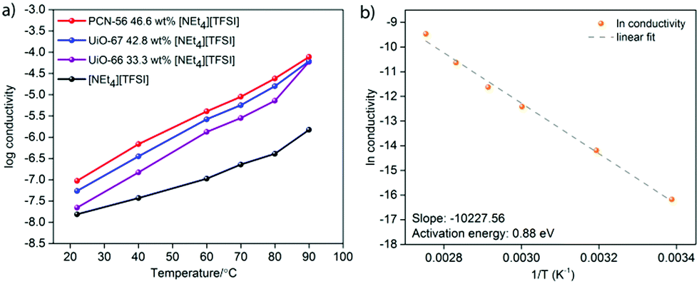 | ||
| Fig. 4 (a) Temperature dependence of conductivity of [NEt4][TFSI] and three [NEt4][TFSI]-MOF composites, and (b) Arrhenius plot for the conductivity of the PCN-56-[NEt4][TFSI] composite with 46.6 mass% [NEt4][TFSI]. | ||
Fig. 4b is an Arrhenius plot for the conductivity of the PCN-56-[NEt4][TFSI] composite with 46.6 mass% [NEt4][TFSI]. The calculated activation energy (Ea) of conductivity is 0.88 eV, compared to 0.58 eV for neat [NEt4][TFSI] (see ESI,† Fig. S13–S16 and Tables S3–S20 for Arrhenius plots and calculated Ea for neat [NEt4][TFSI] and for other MOF-[NEt4][TFSI] composites). For PCN-56-[NEt4][TFSI] to have a conductivity higher than that of neat [NEt4][TFSI] by an order of magnitude or more, despite having a significantly higher Ea of conductivity, indicates that there is a much higher charge carrier density in PCN-56-[NEt4][TFSI] composite than in crystalline [NEt4][TFSI]. Adsorption of the salt in the MOF results in a non-crystalline salt with an extremely high concentration of mobile ions, particularly when the MOF is less-than-completely full, leaving vacancies that enhance ion mobility. That results in a much higher concentration of mobile ions than would be present in the crystalline salt [NEt4][TFSI]. The high Ea of conductivity in the MOF-salt composite compared to the crystalline salt [NEt4][TFSI] indicates that there is a lower-energy pathway for ion movement in the crystalline salt than in the salt loaded in the MOF—a surprising result. The low Ea for pure [NEt4][TFSI] is due to unusually facile ion motion in a crystalline salt—it might be considered an “organic ionic plastic crystal”.33 The relatively higher Ea in the PCN-56-[NEt4][TFSI] composite indicates that there are fairly strong MOF-ion interactions. This points to a means by which the conductivity of such composites can be increased—MOFs with weaker interactions with the salt will likely lead to lower Ea and higher conductivity.
In conclusion, the spatial confinement of [NEt4][TFSI] in the nanoscale pores of three different MOFs results in an increase of its ionic conductivity compared to pure [NEt4][TFSI], with the greatest enhancement in conductivity for the MOF with the largest pores. In all three MOFs, the maximal increase in conductivity was achieved with a loading of salt that was slightly less than that required for complete filling of the MOF pores. The Ea of conductivity is higher in the MOF-salt composites than in the pure salt, but the significantly higher concentration of mobile ions in the composites results in a higher conductivity than in the neat salt.
This work was supported as part of the Joint Center for Energy Storage Research (JCESR), an Energy Innovation Hub funded by the U.S. Department of Energy, Office of Science, Basic Energy Sciences.
Conflicts of interest
There are no conflicts to declare.Notes and references
- X.-B. Cheng, R. Zhang, C.-Z. Zhao and Q. Zhang, Chem. Rev., 2017, 117, 10403–10473 CrossRef CAS PubMed.
- T. Famprikis, P. Canepa, J. A. Dawson, M. S. Islam and C. Masquelier, Nat. Mater., 2019, 18, 1278–1291 CrossRef CAS PubMed.
- P. Knauth, Solid State Ionics, 2009, 180, 911–916 CrossRef CAS.
- C. C. Liang, J. Electrochem. Soc., 1973, 120, 1289–1292 CrossRef CAS.
- J. Maier, Prog. Solid State Chem., 1995, 23, 171–263 CrossRef CAS.
- H. Maekawa, R. Tanaka, T. Sato, Y. Fujimaki and T. Yamamura, Solid State Ionics, 2004, 175, 281–285 CrossRef CAS.
- H. Maekawa, Y. Fujimaki, H. Shen, J. Kawamura and T. Yamamura, Solid State Ionics, 2006, 177, 2711–2714 CrossRef CAS.
- H. Furukawa, K. E. Cordova, M. O’Keeffe and O. M. Yaghi, Science, 2013, 341, 1230444 CrossRef PubMed.
- S. Seth, T. P. Vaid and A. J. Matzger, Dalton Trans., 2019, 48, 13483–13490 RSC.
- Z. Wang, R. Tan, H. Wang, L. Yang, J. Hu, H. Chen and F. Pan, Adv. Mater., 2018, 30, 1704436 CrossRef PubMed.
- Z. Wang, Z. Wang, L. Yang, H. Wang, Y. Song, L. Han, K. Yang, J. Hu, H. Chen and F. Pan, Nano Energy, 2018, 49, 580–587 CrossRef CAS.
- E. M. Miner and M. Dincă, Philos. Trans. R. Soc., A, 2019, 377, 20180225 CrossRef CAS PubMed.
- B. M. Wiers, M.-L. Foo, N. P. Balsara and J. R. Long, J. Am. Chem. Soc., 2011, 133, 14522–14525 CrossRef CAS PubMed.
- R. Ameloot, M. Aubrey, B. M. Wiers, A. P. Gómora Figueroa, S. N. Patel, N. P. Balsara and J. R. Long, Chem. – Eur. J., 2013, 19, 5533–5536 CrossRef CAS PubMed.
- S. S. Park, Y. Tulchinsky and M. Dincă, J. Am. Chem. Soc., 2017, 139, 13260–13263 CrossRef CAS PubMed.
- S. Fischer, J. Roeser, T. C. Lin, R. H. DeBlock, J. Lau, B. S. Dunn, F. Hoffmann, M. Fröba, A. Thomas and S. H. Tolbert, Angew. Chem., Int. Ed., 2018, 57, 16683–16687 CrossRef CAS PubMed.
- L. Shen, H. B. Wu, F. Liu, J. L. Brosmer, G. Shen, X. Wang, J. I. Zink, Q. Xiao, M. Cai, G. Wang, Y. Lu and B. Dunn, Adv. Mater., 2018, 30, 1707476 CrossRef PubMed.
- K. Jeong, S. Park, G. Y. Jung, S. H. Kim, Y.-H. Lee, S. K. Kwak and S.-Y. Lee, J. Am. Chem. Soc., 2019, 141, 5880–5885 CrossRef CAS PubMed.
- K. Fujie and H. Kitagawa, Coord. Chem. Rev., 2016, 307, 382–390 CrossRef CAS.
- I. Cota and F. Fernandez Martinez, Coord. Chem. Rev., 2017, 351, 189–204 CrossRef CAS.
- F. P. Kinik, A. Uzun and S. Keskin, ChemSusChem, 2017, 10, 2842–2863 CrossRef CAS PubMed.
- S. Zhang, J. Zhang, Y. Zhang and Y. Deng, Chem. Rev., 2017, 117, 6755–6833 CrossRef CAS PubMed.
- Q. Luo, B. An, M. Ji and J. Zhang, Mater. Chem. Front., 2018, 2, 219–234 RSC.
- K. Fujie, K. Otsubo, R. Ikeda, T. Yamada and H. Kitagawa, Chem. Sci., 2015, 6, 4306–4310 RSC.
- Y. Yoshida, K. Fujie, D.-W. Lim, R. Ikeda and H. Kitagawa, Angew. Chem., Int. Ed., 2019, 58, 10909–10913 CrossRef CAS PubMed.
- M. J. Katz, Z. J. Brown, Y. J. Colón, P. W. Siu, K. A. Scheidt, R. Q. Snurr, J. T. Hupp and O. K. Farha, Chem. Commun., 2013, 49, 9449–9451 RSC.
- H.-L. Jiang, D. Feng, T.-F. Liu, J.-R. Li and H.-C. Zhou, J. Am. Chem. Soc., 2012, 134, 14690–14693 CrossRef CAS PubMed.
- K. Fujie, T. Yamada, R. Ikeda and H. Kitagawa, Angew. Chem., Int. Ed., 2014, 126, 11484–11487 CrossRef.
- W. A. Henderson, D. M. Seo, Q. Zhou, P. D. Boyle, J.-H. Shin, H. C. D. Long, P. C. Trulove and S. Passerini, Adv. Energy Mater., 2012, 2, 1343–1350 CrossRef CAS.
- G. C. Shearer, S. Chavan, J. Ethiraj, J. G. Vitillo, S. Svelle, U. Olsbye, C. Lamberti, S. Bordiga and K. P. Lillerud, Chem. Mater., 2014, 26, 4068–4071 CrossRef CAS.
- A. B. Kanj, R. Verma, M. Liu, J. Helfferich, W. Wenzel and L. Heinke, Nano Lett., 2019, 19, 2114–2120 CrossRef CAS PubMed.
- J. H. Cavka, S. Jakobsen, U. Olsbye, N. Guillou, C. Lamberti, S. Bordiga and K. P. Lillerud, J. Am. Chem. Soc., 2008, 130, 13850–13851 CrossRef PubMed.
- H. Zhu, D. R. MacFarlane, J. M. Pringle and M. Forsyth, Trends Chem., 2019, 1, 126–140 CrossRef.
Footnote |
| † Electronic supplementary information (ESI) available: Experimental methods, N2 sorption isotherms, PXRD patterns, DSC data, EIS data, Arrhenius plots and calculations of Ea. See DOI: 10.1039/d0cc03147j |
| This journal is © The Royal Society of Chemistry 2020 |