 Open Access Article
Theoretical tuning of Ruddlesden–Popper type anti-perovskite phases as superb ion conductors and cathodes for solid sodium ion batteries†
Yuran
Yu
 ab,
Zhuo
Wang
 *ab and
Guosheng
Shao
 *ab
*ab
aState Center for International Cooperation on Designer Low-carbon & Environmental Materials (CDLCEM), Zhengzhou University, 100 Kexue Avenue, Zhengzhou 450001, China
bZhengzhou Materials Genome Institute (ZMGI), Zhongyuanzhigu, Building 2, Xingyang 450100, China. E-mail: gsshao@zzu.edu.cn; wangzh@zzu.edu.cn
First published on 8th April 2019
Abstract
It is very important and yet extremely challenging to develop solid-state electrolytes for safe sodium ion batteries, largely due to sodium ions being significantly larger than lithium ones. Here in this work we have carried out systematic modelling, using a materials genome approach in the framework of density functional theory (DFT), to formulate a new system of ion conductors and compatible cathodes. Through iso-valent substitution of both the anion and cation sites in a Na4OI2 compound with a Ruddlesden–Popper type phase based on sheets of anti-perovskite structural units, or an anti-Ruddlesden–Popper phase (ARP), we have identified a series of stable layer-structured phases, with the general formula Na4−cLicAX4 (A = O and/or S; X = I and/or Cl), as remarkable electrolytes and high capacity cathodes to enable solid sodium ion batteries. The optimized Na3LiS0.5O0.5I2 compound is a marvellous Na+ conductor, with an extremely low activation energy for Na+ transportation (0.12 eV) and a high Na+ conductivity of 6.3 mS cm−1 at standard room temperature (298 K). This superb solid electrolyte does not react with the sodium anode, and formation of layer-structured phases due to its sodium depletion leads to compatible cathode materials with high voltage plateaus to enable full batteries with high energy densities.
Introduction
With ever pressing needs for high performance metal ion batteries essential to modern society,1–3 greater and greater efforts have been directed towards developing alternative metal ion batteries4–8 beyond Li-ion batteries (LIBs), due to limited lithium resources. Naturally, sodium-ion batteries (SIBs) are among the most attractive ones, owing to the nearly inexhaustible resource of sodium and its much lower price.9 One of the main areas of focus in SIBs lies in developing safer electrolytes, as current liquid organic electrolytes are rather flammable.10–14 Such a drawback needs to be overcome before the technology can take off for wide applications, since SIBs are more suitable for application in large scale energy storage due to their less competitive energy density than LIBs,4,15 thus making the safety requirement even more demanding. Indeed, safety issues are one of the major generic concerns for secondary metal ion batteries based on liquid organic electrolytes,12 which is the very driving factor in developing solid-state batteries employing non-flammable inorganic solid-state electrolytes (SSEs).10,11,15 From the end users' point of view, an ideal SSE for SIBs is expected to meet the following criteria16: (a) high Na+ conductivity greater than 1 mS cm−1; (b) electrically insulating to avoid self-discharging in batteries; (c) structurally/energetically stable to safeguard dependable service in a wide temperature range, e.g. from −50 to 250 °C; (d) electrochemically compatible with the sodium anode, so as to make use of the highest energy density of sodium (1.16 A h g−1); and (e) light weight, economical, and environmentally friendly.As sodium and lithium are neighbouring alkali metals with similar chemical properties, knowledge on solid lithium conductors has been naturally extended into developing solid electrolytes for SIBs,11,12,17–19 in particular through straightforward substitution of Li by Na in known SSEs for LIBs.15 However, distinct differences exist between Na+ and Li+ ions. Na+ ions are about 26% larger than Li+ ions (ionic radii 1.02 Å vs. 0.76 Å, respectively),4,15 and they are also much heavier (23 g mol−1 of Na+vs. 6.9 g mol−1 of Li+).15 Furthermore, the standard electrode potential of sodium (−2.71 V vs. standard hydrogen electrode, SHE) is higher than that of lithium (−3.05 V vs. SHE).4 Such major differences contribute to the greater difficulty in developing solid electrolytes with superb Na+ conductivity to rival liquid electrolytes.
Great efforts have been made to develop potential SSEs for SIBs based on sulfides.13 Na+ conductivity in Na10SnP2S12,19 by replacing Li with Na in Li10GeP2S12 (LGPS), was 0.4 mS cm−1 at room temperature, which is lower than the critical request of 1 mS cm−1. The activation barrier for Na+ diffusion in Na10SnP2S12 was also too high (0.356 eV). Subsequently, Na+ transportation was improved significantly through the slight stoichiometric offset with excess Na, so that the activation energy for Na+ diffusion in Na11Sn2PS12 (ref. 20) was lowered to 0.25 eV. The total ionic conductivity reached 1.4 mS cm−1 at room temperature, which is still marginal for a competitive solid electrolyte to function adequately below 0 °C. Furthermore, due to the inheritance of the tetrahedral PS4 and SnS4 units from the LGPS system,17,18 the electrolyte is not compatible with the Na anode, with a tendency to be decomposed into NaxP, Na2S etc.20,21 The stability window of Na11Sn2PS12 is only 0.57 V (from 1.25 to 1.82 V vs. Na), which cannot prevent undesirable interphase formation below 1.25 V with the Na anode, or above 1.82 V with the cathode. The narrow electrochemical window and the incompatibility with the Na anode for Na11Sn2PS12 would significantly hinder construction of all-solid SIBs with sodium anodes for high energy density.
A narrow electrochemical window is one of the major shortcomings for alkali-metal phosphor-sulfides.22–28 It is highly encouraging to notice that sodium hali-oxides such as Na3OX with cubic anti-perovskite structures are compatible with Na anodes (X: halogen).29 More intriguingly, a layered Na4OI2 compound was found to be stable at room temperature. Such a layered phase belongs to the anti-perovskite group, containing plenty of Na+ ions with a 57% atomic percentage in its unit cell.29–31 However, experimental studies revealed that the Na+ conductivity in Na4OI2 was too poor, only 0.03 mS cm−1 even at an elevated temperature of 180 °C.32 It is therefore highly useful to devise a theoretical roadmap to guide effective tuning of materials chemistry of Na4OI2 based materials, so that practical delivery of superb Na+ conductors can be achieved cost-effectively, thus enabling high-performance solid state SIBs.
Here in this work, we have carried out systematic modelling on the basis of a materials genome approach in the framework of density functional theory (DFT).7,16,18,33–35 On the basis of a high throughput simulation, we have identified effective routes for remarkable enhancement of ionic conductivity, based on Na4AX2 (A = chalcogen and X = halogen). This covers the effects of smaller halogen anions on the X sites, substitution of O−2 with chalcogen species with weaker electronegativities on the A sites, and co-alloying on both the A and X sites. Through extensive screening of numerous structural configurations, we have identified the best sodium hali-chalcogenide candidate with the stoichiometry of Na4S0.5O0.5I2, which is thermodynamically and dynamically stable. The ionic conductivity of Na4S0.5O0.5I2 reaches 0.347 mS cm−1 with a moderate activation energy Ea of 0.23 eV. More importantly, through the replacement of a quarter of the Na+ site by Li+, we have identified a hybrid SSE of Na3LiS0.5O0.5I2 as a superb Na+ conductor, which permits Na+ conductivity up to 6.3 mS cm−1 at 25 °C, together with an extremely low activation energy of 0.12 eV. Such high performance and electrochemical compatibility with the sodium anode is to provide a fundamentally solid basis to enable high ionic conductivity well below 0 °C, which is key for high performance solid SIBs.
Methods
Theoretical calculations were performed using the Vienna Ab Initio Simulation Package (VASP),36,37 with the ionic potentials including the effect of core electrons being described by the projector augmented wave (PAW) method.38,39 In this work, the Perdew–Burke–Ernzerhof (PBE) exchange–correlation (XC) functionals40,41 are used to study the structural stabilities of the Na4AX2 family. For geometric relaxation of the structures, summation over the Brillouin Zone (BZ) is performed with Monkhorst–Pack k-point intervals limited below 0.04 Å−1 for both conventional and primitive cells.42 A plane-wave energy cutoff of 600 eV was used in all calculations. All structures were geometrically relaxed until the total force on each ion was reduced below 0.01 eV Å−1.43–45 For the calculations of electronic energy band structures, we used the HSE06 functional to predict more accurate values of band gaps.46,47 We employed a convergence criterion of 10−6 eV, adequate for electronic self-consistent cycles.The universal structure predictor (USPEX)48,49 based on energy minimization was employed to predict stable or metastable structures for any given composition. For each composition, a population of 230 possible structures was randomly created with varied symmetries in the first generation. When the full structure relaxation was reached, the most stable and metastable structures, through the comparison of enthalpy of formation, were placed into the next generation. Afterwards, each subsequent generation would be created through heredity, with lattice mutation and permutation operators being applied and assessed energetically for the selection of a population of 60 for the next run. USPEX would continue screening the structures until the most stable configuration remained unchanged for a further 20 generations to safeguard the global equilibrium.34
The energy (enthalpy) of formation of each NaaSbOcIdCle compound was defined with respect to the chemical potentials of the constituent phases as
| Ef = Ec − bENa2S − cENa2O − dENaI − eENaCl | (1) |
The phonon frequency spectrum of a theoretically predicted structure was used for examining its dynamic stability. The supercell method in the PHONOPY package50,51 was employed to perform the relevant frozen-phonon calculations based on harmonic approximation. The supercells of relaxed structures were used for phonon calculations. The stability criterion is that the amplitude of imaginary frequency is less than −0.3 THz,52,53 to accommodate acceptable numerical errors in phonon calculations.
In our recent tests, ab initio molecular dynamics (AIMD) can be carried out to describe the ionic transport behaviour at elevated temperatures to provide further insights via statistical processes,33,54–56 for which the diffusion coefficient D and associated ionic conductivity σ at any temperature can be estimated. In order to ensure a manageable AIMD analysis, simulation runs were performed on supercells of Na4(1–x)LixAaXb with a time step of 2 fs in the NVT ensembles together with a Nosé–Hoover thermostat. Each AIMD run lasted for 80 ps after a pre-equilibrium run of 10 ps. In order to shorten the simulation time, elevated temperatures of 900 to 1300 K were employed to accelerate the ion hopping process (details of AIMD simulation are presented in S2 of the ESI†).
The Alloy-Theoretic Automated Toolkit (ATAT)57,58 is based on the method of cluster expansion, which is a powerful tool to establish phase equilibria of interest through minimization of the formation energies of variable compositions using first-principles calculations. A cluster expansion is considered to be converged when all the following conditions are satisfied: (a) all ground states are correctly reproduced, (b) no other new ground states are predicted, and (c) the cross-validation score is typically less than 0.025 eV. Therefore, energies predicted from the cluster expansion as a function of composition for each structure are generated. On the basis of the ground states for each composition, a convex hull is created to describe the phase equilibrium.
According to the low-energy states on the minimal edge of the convex hull, the average electrochemical potential ![[V with combining macron]](https://www.rsc.org/images/entities/i_char_0056_0304.gif)
![[A with combining right harpoon above (vector)]](https://www.rsc.org/images/entities/char_0041_20d1.gif) B, for the transition between state A (NaxΠ) and state B (Nax+ΔxΠ), with reference to electrochemical potential vs. Na/Na+ related to total energies (Et) can be calculated by:
B, for the transition between state A (NaxΠ) and state B (Nax+ΔxΠ), with reference to electrochemical potential vs. Na/Na+ related to total energies (Et) can be calculated by:
![[V with combining macron]](https://www.rsc.org/images/entities/i_char_0056_0304.gif) ![[A with combining right harpoon above (vector)]](https://www.rsc.org/images/entities/char_0041_20d1.gif) B = −1/z{[Et(Nax+ΔxΠ) − Et(NaxΠ)]/Δx − Et(Na)} B = −1/z{[Et(Nax+ΔxΠ) − Et(NaxΠ)]/Δx − Et(Na)} | (2) |
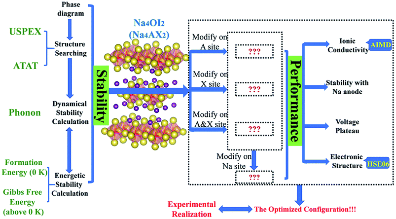
Overall, theoretical formulation for a competitive solid electrolyte involves phase stability, electrochemical stability against electrodes, ionic conductivity and electrochemical potential, as well as energy band structures. The phase stability aspect of modelling covers the stable and metastable structures for each composition (USPEX and PHONOPY), phase stability with respect to stable constituent phases (USPEX and PHONOPY), phase equilibria with respect to compositional change (ATAT), and potential reactions at interfaces, e.g. those with electrodes. Modelling of functional performance includes ionic conductivity (AIMD) and electrochemical potentials associated with electrolyte compositions and structures (eqn (2)).
A summary of methods as an integrated materials genome approach for the current work is presented in Fig. 1. A potential stable phase for each given composition can be identified, when it is energetically and dynamically stable, together with a negative energy above the hull to account for global equilibration. An allowance of 25 meV per atom can be considered for the formation energy at 0 K to accommodate thermal fluctuation at standard room temperature (298 K).19,59,60
The compositional dependence of phase stability, which is typically involved at interfaces between any two terminal compositions, can be readily simulated with the ATAT code, which results in a convex hull of formation energies, thus leading to identification of thermodynamically stable phases between the stable phases of the terminal substances. Application of a PHONOPY simulation to thermodynamically stable structures leads to assessment of dynamical stability and phonon entropy as a major contribution to Gibbs free energy.7,16,18,33,54,61
Discussion
The pristine Na4OI2 phase stability
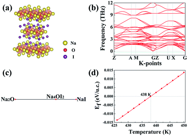
The Na4OI2 compound was synthesized through a solid-state reaction at about 350 °C previously.29 Let us examine the structural stability of the Na4OI2 configuration using USPEX as a materials genome tool based on global energy minimization at 0 K, which identifies the most stable structure for the Na4OI2 composition, as shown in Fig. 2(a). The stable Na4OI2 phase contains layers of Na6O4+ octahedral units, which are basic units in a cubic anti-perovskite phase such as Na3OCl with the PM![[3 with combining macron]](https://www.rsc.org/images/entities/char_0033_0304.gif) M(221) space group. The I− anions sitting between the octahedral layers help in binding with Na+ cations in between, thus leading to a tetragonal lattice with the space group of I
M(221) space group. The I− anions sitting between the octahedral layers help in binding with Na+ cations in between, thus leading to a tetragonal lattice with the space group of I![[4 with combining macron]](https://www.rsc.org/images/entities/char_0034_0304.gif) MMM(139). Such a phase is of the same layered characteristics of the Ruddlesden–Popper phase,62–64 albeit being based on anti-perovskite structural units instead of perovskite units. It is thus termed as an anti-Ruddlesden–Popper (ARP) phase in this work. Also, PHONOPY calculations, within the quasi-harmonic approximation, show that the Na4OI2 phase (126 atoms) is dynamically or mechanically stable, with no states associated with imaginary frequencies, Fig. 2(b).
MMM(139). Such a phase is of the same layered characteristics of the Ruddlesden–Popper phase,62–64 albeit being based on anti-perovskite structural units instead of perovskite units. It is thus termed as an anti-Ruddlesden–Popper (ARP) phase in this work. Also, PHONOPY calculations, within the quasi-harmonic approximation, show that the Na4OI2 phase (126 atoms) is dynamically or mechanically stable, with no states associated with imaginary frequencies, Fig. 2(b).
In addition, the ground state Na4OI2 phase is stable with respect to constituent binary phases Na2O and NaI at 0 K, with the pseudo-binary phase diagram being shown in Fig. 1(c). Temperature dependence of phase equilibria can be derived with the consideration of the phonon entropy in Gibbs energies:
| ΔGNa4OI2 = GNa4OI2 − GNa2O − 2GNaI | (3) |
Since the pristine Na4OI2 is known to be a rather poor conductor for Na+ ions, it is necessary to tune its materials chemistry in order to meet requests for competitive SSEs. This involves tailoring materials chemistry over every sublattice site based on M4AX2 (M = alkali metal, A = chalcogen, and X = halogen).
Iso-valent substitution in Na4AX2
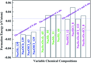
Stable and metastable structures for each possible Na4AX2 chemical component are identified by USPEX through global energy minimization. The energy of formation of each compound is defined against its stable constituent phases (i.e. the energies above the hull), e.g. Na2O, Na2S, NaCl and NaI. The outcome is summarized in Fig. 3.Iso-valent substitution of I− on the halogen X site with a smaller halogen species Cl− results in stable compounds with respect to the constituent binary phases. While complete replacement of I− by Cl− still keeps the same lattice symmetry as the stable structure, Na4OCl2_139 (numerable refers to space group number 139), partial substitution of I by Cl leads to stable and metastable compounds with different space groups, Na4OICl_63 and Na4OICl_129. The corresponding formation energies are −0.0098, −0.0114 and −0.004 eV per atom (vs. formation energy for Na4OI2 −0.027 eV per atom), so that they are more stable than the constituent binary phases at 0 K (in terms of energies: Na4OCl2 < Na2O + 2NaCl, Na4OICl < Na2O + NaI + NaCl).
On the chalcogen A site, replacement of O by S results in Na4S0.5O0.5I2_65, Na4SI2_55, Na4SI2_11 and Na4SI2_64. The corresponding formation energies for them are 0.006, 0.0323, 0.0326 and 0.0334 eV per atom above the hull, which are only slightly less stable than their constituent phases.
In the case of iso-valent substitution on both the chalcogen (A) and the halogen (X) sites, four energetically favoured structures emerge as Na4SICl_12 (0.024 eV per atom), Na4SICl_8 (0.050 eV per atom), Na4S0.5O0.5ICl_123 (0.024 eV per atom), and Na4S0.5O0.5ICl_8 (0.031 eV per atom). Table 1 summarizes the USPEX searched structures, covering space groups and lattice parameters. The emboldened phases are stable with respect to constituent phases, and those starred are also considered as potential candidates for practical synthesis, with formation energies above the hull not exceeding the 0.025 eV per atom marker.
| Configuration | A | B | c (Å) | α | β | γ (°) | Symmetry |
|---|---|---|---|---|---|---|---|
| Na4OI2_139 | 4.6714 | 4.6714 | 16.1014 | 90 | 90 | 90 |
I![[4 with combining macron]](https://www.rsc.org/images/entities/char_0034_0304.gif) MMM(139) MMM(139) |
| Na4OCl2_139 | 4.4066 | 4.4066 | 14.2356 | 90 | 90 | 90 |
I![[4 with combining macron]](https://www.rsc.org/images/entities/char_0034_0304.gif) MMM(139) MMM(139) |
| Na4OICl_63 | 4.5745 | 19.7556 | 6.823 | 90 | 90 | 90 | CMCM(63) |
| Na4OICl_129 | 4.517 | 4.517 | 15.0419 | 90 | 90 | 90 |
P![[4 with combining macron]](https://www.rsc.org/images/entities/char_0034_0304.gif) NMM(129) NMM(129) |
| Na4S0.5O0.5I2_65 | 16.3097 | 6.9654 | 9.9591 | 90 | 90 | 90 | CMMM(65) |
| Na4SI2_11 | 7.0334 | 4.5365 | 13.6175 | 90 | 88.1004 | 90 |
P2![[1 with combining macron]](https://www.rsc.org/images/entities/char_0031_0304.gif) M(11) M(11) |
| Na4SI2_55 | 7.6833 | 13.2245 | 4.4076 | 90 | 90 | 90 | PBAM(65) |
| Na4SI2_64 | 7.4196 | 16.4631 | 7.5097 | 90 | 90 | 90 | CMCA(64) |
| Na4SICl_8 | 25.2976 | 4.5048 | 7.356 | 90 | 88.0375 | 90 | CM(8) |
| Na4SICl_12 | 24.1735 | 4.3758 | 7.7573 | 90 | 99.3575 | 90 |
C![[2 with combining macron]](https://www.rsc.org/images/entities/char_0032_0304.gif) M(12) M(12) |
| Na4S0.5O0.5ICl_8 | 21.4945 | 4.68504 | 7.096 | 90 | 90.0102 | 90 | CM(8) |
| Na4S0.5O0.5ICl_123 | 4.7755 | 4.7755 | 15.2731 | 90 | 90 | 90 |
P![[4 with combining macron]](https://www.rsc.org/images/entities/char_0034_0304.gif) MMM(123) MMM(123) |
The chosen phase from Na4AX2
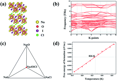
Among the three energetically favoured structures of Na4OCl2_139, Na4OICl_63 and Na4OICl_129, the Na4OICl_63 phase is the most stable with respect to stable constituent phases, with the halogen sites equally shared by Cl− and I−. The phase is base centred, with the CMCM space group symmetry (number 63), Fig. 4(a), which is characteristic of the zigzag layers of Na6O4+ units, the basic octahedra in the layers as a framework of the Na4OI2_139 phase. While rows of I− anions appear along the hollow space within each zigzag layer of octahedra, rows of Cl− anions are present between the layers. Of the two types of halogen anions, the smaller but stronger Cl− anions largely contribute to bind the zigzag layers via electrostatic attraction with Na cations, while the weaker I− anions stay in the hollow space to help brace up the layered structure via electrostatic repelling the neighbouring rows of Cl− anions. Therefore, it is the combined geometric and electrostatic factors that lead to dramatic reconstruction of initially flat sheets of octahedra, the basic units in anti-perovskites, into matching zigzag layers, Fig. 4(a).The ground state stable phase of Na4OICl (space group number 63) is also confirmed to be dynamically stable owing to the lack of phonon states associated with imaginary frequencies, as shown by the phonon band structure from its 2 × 2 × 1 supercell containing 28 atoms, Fig. 4(b). The zigzag structural framework containing alternating rows of I− and Cl− anions is therefore dynamically stable as well. It is well recognized that dynamically stable phases, even those with energy slightly above the hull, tend to exist in nature.
The ground state phase diagram for the formation of Na4OICl_63 is shown in Fig. 4(c), which is in equilibrium with the three constituent phases Na2O, NaI and NaCl at 0 K. The free energy above the hull, within the quasi-harmonic approximation to consider the phonon entropy, can therefore be defined as:
| ΔGNa4OICl = GNa4OICl − GNa2O − GNaI − GNaCl | (4) |
It follows that ΔGNa4OICl turns out to be positive above a critical temperature of 826 K, Fig. 4(d), so that this phase is stable within a much wider temperature range than the pristine phase of Na4OI2_139 (826 K vs. 438 K). Such an outstanding combination of energetic and dynamical stability indicates it would be much easier for its practical delivery in a wide temperature window for processing, e.g. through mechanical alloying followed by power sintering.35
However, the other two energetically stable compounds, Na4OCl2 (I![[4 with combining macron]](https://www.rsc.org/images/entities/char_0034_0304.gif) MMM(139)) and Na4OICl (P
MMM(139)) and Na4OICl (P![[4 with combining macron]](https://www.rsc.org/images/entities/char_0034_0304.gif) NMM(129)), are not dynamically stable, as exhibited in Fig. S1(a) and (b),† respectively. The phonon band structures for each of them have bands associated below the −0.3 THz threshold, Fig. S1(a′) and (b′).†
NMM(129)), are not dynamically stable, as exhibited in Fig. S1(a) and (b),† respectively. The phonon band structures for each of them have bands associated below the −0.3 THz threshold, Fig. S1(a′) and (b′).†
Optimization on the A site of Na4AX2
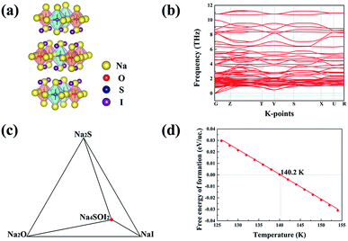
USPEX searching results in four potential structural configurations, i.e. Na4S0.5O0.5I2_65, Na4SI2_55, Na4SI2_11 and Na4SI2_64. The most stable one, Na4S0.5O0.5I2_65 with the CMMM symmetry, has a negligible energy above the hull (0.006 eV) at 0 K. This energetically favoured phase is characterized with planar layers made of alternating Na6O4+ and Na6S4+ octahedra. Such alternating arrangement of chalcogen octahedra is characteristic of cubic double anti-perovskite phases,33 and we therefore can classify this phase as a double anti-Ruddlesden–Popper phase (DARP) based on interlocking Na4OI2_139 and Na4SI2_139 APR units, Fig. 5(a).Besides, the Na4S0.5O0.5I2_65 (112 atoms) is also dynamically stable without any phonon bands related to imaginary frequencies, Fig. 5(b). The free energy above the hull for Na4S0.5O0.5I2_65 is,
| ΔGNa4S0.5O0.5I2 = GNa4S0.5O0.5I2 − 0.5GNa2S − 0.5GNa2O − 2GNaI | (5) |
As is shown in Fig. 5(d), ΔGNa4S0.5O0.5I2 becomes negative above 140 K (−133 °C), indicating that this phase is energetically favoured over any thermal environment of practical interest, e.g. well over room temperature. This is desirable for practical synthesis of the compound so that it can be processed over a very wide temperature range without worrying about its decomposition into constituent binary phases.
The other three candidates, Na4SI2_55, Na4SI2_11 and Na4SI2_64, are slightly less competitive energetically with energies above the hull being close to 0.025 eV (0.0323, 0.0326 and 0.0334 eV correspondingly). The layered structures are maintained with the first two being also dynamically stable, as is evidenced in Fig. S2(a)–(c).†
In the case of iso-valent substitution of both the chalcogen and halogen sites, USPEX searching results in four structural configurations, Na4SICl_12, Na4SICl_8, Na4S0.5O0.5ICl_123, Na4S0.5O0.5ICl_8, as exhibited in Fig. S3.† It is found that the latter two phases, Na4S0.5O0.5ICl_123 and Na4S0.5O0.5ICl_8, are dynamically unstable.
Table S1† summarizes the overall finding on iso-valent substitution in the Na4OI2 phase. In addition to the pristine Na4SI2_139 phase, we have thus identified Na4OICl_63 and Na4S0.5O0.5I2_65 (DARP) as most promising structures with greater stability.
Iso-valent doping on the Na site of Na4AX2
Iso-valent replacement of Na with Li has also been investigated, on the basis of the DARP Na4S0.5O0.5I2 phase, since firstly it has the widest temperature window for both energetic and dynamical stability, and secondly S substitution of O is expected to soften the lattice to induce improved ionic conductivity.18,35 ATAT searching outcome for the stable configurations is represented as an convex hull, through the combination of DFT with cluster expansion simulation over Na4(1–x)LixS0.5O0.5I2 (0 ≤ x≤ 1). As is shown in Fig. 6(a), the most stable structural configuration is based on substitution of a quarter of the Na site by Li. On the basis of chemical potential minimization, the stable phases are those sitting over the minimal common tangents between any two points on the bottom edge of the convex hull. Consequently, Fig. 6(a) suggests unlimited potential for mixing Na4S0.5O0.5I2 with Li4S0.5O0.5I2 into alloys. Substitution of a quarter of the Na sites leads to the structure shown in Fig. 6(b), which is also dynamically stable owing to the lack of phonon bands associated with imaginary frequencies, as shown in Fig. 6(c), a phonon band structure from its 2 × 1 × 2 supercell containing 112 atoms.Ionic conductivity
Ionic conductivity is determined by the diffusion of alkali ions. Fig. 7 shows the plot of the Arrhenius relationships of potential electrolytes of interest, with a vacancy of Na+ being considered for every 32 alkali ions, similar to the vacancy ionic transportation mechanism illustrated in the anti-perovskite system.16,33,65 Data derived from Fig. 7 are summarized in Table 2. For the pristine Na4OI2 phase, the activation barrier of Ea = 0.37 eV is largely consistent with the result of 0.3 eV from LST/QST simulation using CASTEP.32 The corresponding Na+ conductivity (σ) is only 5.89 × 10⁻² mS cm−1 at room temperature (298 K). Introducing Cl− to share the halogen site with I− leads to an even bigger activation barrier for Na+ diffusion in Na4OICl (0.44 eV), together with poorer Na+ conductivity as low as 8.79 × 10⁻⁴ mS cm−1 at room temperature. This is understandable, considering that stronger electrostatic attraction to the interlayer Cl− anions tends to keep Na+ from hopping (layers of the zigzag structural framework are closer to each other, thus hindering the migration of Na+ ions). On the other hand, with 50% S substitution of the O site in Na4OI2, the activation barrier in Na4S0.5O0.5I2_65 (i.e. Na31S4O4I16) is reduced significantly down to 0.23 eV, with Na+ ion conductivity increased over two order up to 0.347 mS cm−1 at room temperature. This is comparable to the best reported data for solid sodium ion conductors such as Na11Sn2PS12 (Ea = 0.25 eV, σ = 1.4 mS cm−1 at 300 K).20 Such significant improvement of ionic conductivity through substitution of O with S is consistent with recent theoretical prediction and experimental confirmation that the reduced electrostatic attraction between S and alkali ions leads to lattice softening.18,35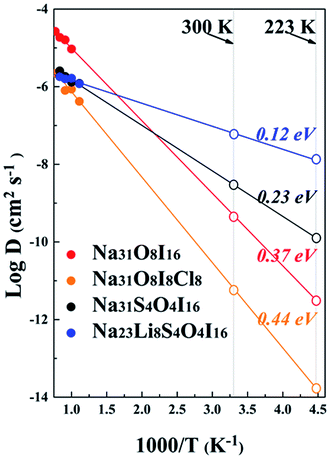 | ||
| Fig. 7 Diffusion coefficients for sodium ions from AIMD simulation. The extrapolated D values at room temperature and −50 °C are presented by open patterns on the right. | ||
| System | Activation barrier (eV) | Arrhenius prefactor (cm−2 s−1) | Density (10−23 cm−3) |
D
300![[thin space (1/6-em)]](https://www.rsc.org/images/entities/char_2009.gif) K (cm−2 s−1) K (cm−2 s−1) |
σ (mS cm−1) | |
|---|---|---|---|---|---|---|
| 300 K | 223 K | |||||
| Na4OI2 | 0.37 | 7.22 × 10⁻⁴ | 25.553 | 4.266 × 10⁻¹⁰ | 5.89 × 10⁻² | 4.17 × 10⁻⁴ |
| Na4OICl | 0.44 | 1.17 × 10⁻⁴ | 21.3876 | 5.5 × 10⁻¹² | 8.79 × 10⁻⁴ | 2.54 × 10⁻⁶ |
| Na4S0.5O0.5I2 | 0.23 | 2.23 × 10⁻⁵ | 27.8576 | 2.75 × 10⁻⁹ | 0.347 | 0.016 |
| Na3LiS0.5O0.5I2 | 0.12 | 5.76 × 10⁻⁶ | 25.0532 | 6.053 × 10⁻⁸ | 6.3 | 1.31 |
It is amazing to find that in the case of the hybrid electrolyte Na3LiS0.5O0.5I2, the activation barrier in Na23Li8S4O4I16 is reduced by a further half down to 0.12 eV, together with a remarkable Na+ conductivity of up to 6.3 mS cm−1 (4.5 times of that in Na11Sn2PS12). The very low activation energy also helps safeguard an ionic conductivity of 1.31 mS cm−1 at −50 °C, which is extremely useful for a promising SSE. Meanwhile, as shown in Fig. S4,† the mean square displacements (MSDs) of anions, e.g. S−2, O−2, and I−, are minimal, suggesting that they are largely confined around equilibrium positions. On the other hand, Li+/Na+ ions experience long distance transportation in a coordinated way, owing to the great energetic advantage of the stoichiometric composition.
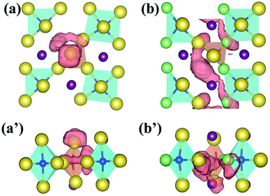
The Na+ ion trajectories for Na4S0.5O0.5I2 and Na3LiS0.5O0.5I2 at 800 K are compared in Fig. 8. In the case of Na4S0.5O0.5I2, the trajectory is still somewhat localized around Na6O4+ octahedral units. When Li+ ions are introduced into the Na+ sites, the long-range transportation of Na+ over half of the unit cell can be observed. The co-existence of smaller Li+ ions, therefore, induces knocking-on effects to promote the transportation of the bigger Na+ ions. The overall Na+/Li+ ion trajectories for Na3LiS0.5O0.5I2 are presented in Fig. S5,† where continuous two-dimensional channels between the layered structural units are clearly revealed. The basic layered structural units are maintained over the AIMD process at such an elevated temperature, indicating high material stability together with high mobility of alkali ions. Such a theoretical observation is similar to the Li+ effect on Mg2+ in the hybrid Li+/Mg+ cathode.7 Huang et al.66 and Du et al.67 reported that a tiny amount of Li+ substitution of Na+ in sodium oxide cathodes NaxTMO2 led to significantly improved electrochemical kinetics and cycling performances, which may be attributed to the same reason as for enhanced Na+ transportation.
Electrochemical compatibility with the Na anode
The interfacial stability between the optimized electrolyte and sodium anode can be investigated by AIMD simulation at elevated temperature, using a sandwich model of Na|Na3LiS0.5O0.5I2|Na, as shown in Fig. S6(a).† It is shown that no interfacial reaction occurs after AIMD simulation for 90 ps well above the melting point of sodium (500 K), Fig. S6 (b).† Besides, the change in pair correlation functions (PCF) for O–Li, O–Na, S–Li and S–Na is shown in Fig. S7,† which demonstrates trivial changes over the simulation time. The Na3LiS0.5O0.5I2 compound is thermodynamically more stable than its constituent binary phases, i.e. E(Na3LiS0.5O0.5I2) < E(0.5Na2O + 0.5Na2S + NaI + LiI), so that there is no energetic driver for phase separation. Since no other stable phases exist between Na and Na2O/Na2S/NaI/LiI,68,69 one can conclude that Na3LiS0.5O0.5I2 does not react with the Na anode. This is consistent with the AIMD simulation more than 100 K above the melting temperature of sodium (Fig. S6a†).From an equilibrium point of view, equilibration associated with depletion of Na+ typically involved with a high voltage cathode material can be investigated by ATAT simulation over Na3(1−y)Li1−xS0.5O0.5I2 (0 ≤ x, y ≤ 1). The identified stable structures are shown in Fig. 9(b), with their corresponding electrochemical potential shown in Fig. 9(a). It is encouraging to note that the lattice mismatches between neighbouring layers are rather limited (2.5–8%), which helps to maintain mechanical integrity when such an interfacial reaction occurs during service.
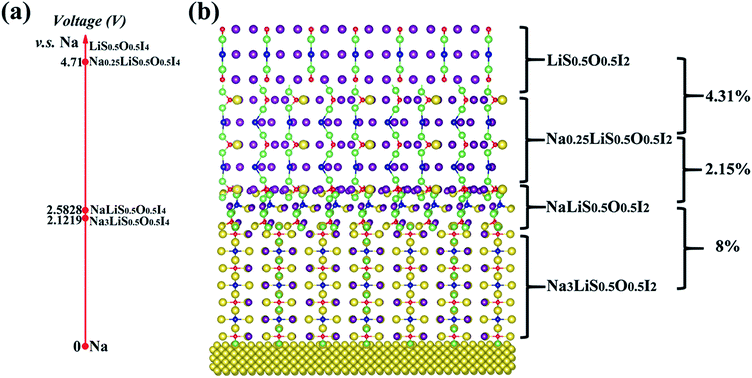 | ||
| Fig. 9 Electrochemical potentials (a) for ground-state stable structures of Na3(1–y)Li1–xS0.5O0.5I2 (0 ≤ x, y ≤ 1) from ATAT simulation. (b) Percentages on the right refer to lattice mismatches. | ||
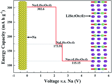
The three stable phases owing to sodium depletion from the optimized electrolyte Na3LiS0.5O0.5I2 are NaLiS0.5O0.5I2, Na0.25LiS0.5O0.5I2 and LiS0.5O0.5I2. The layered structures are largely maintained throughout the sodium depletion process across the three phases, with electrochemical potential (calculated by eqn (2)) increasing with decreasing Na+ content. As the redox potential of Na+/Na is 0.34 V higher than that of Li+/Li, only sodium can deposit or dissolve at the anode, while the Na+ and Li+ hybrid electrolyte acts as an ion reservoir to supply or receive Na+/Li+ during the discharge/charge process. The electrochemical window for the electrolyte Na3LiS0.5O0.5I2 is from 0 to 2.1219 V, and the maximum oxidation voltage plateau reaches 4.71 V through sodium depletion over the Na0.25LiS0.5O0.5I2|LiS0.5O0.5I2 equilibration.
This means that LiS0.5O0.5I2 and metallic sodium can be used as an electrochemically compatible cathode and anode with the Na3LiS0.5O0.5I2 to form a solid sodium battery of Na|Na3LiS0.5O0.5I2|LiS0.5O0.5I2, with evolution of interfacial solid phases being mechanically and electrochemically compatible with the electrolyte and the cathode.16,61,70 The density of states (DOS) for LiS0.5O0.5I2 with metallic characteristics is displayed in Fig. S8,† which indicates that it is a good electronic conductor as a cathode.
In an optimized battery structure, one can make use of a graded battery structure, with each layer being a stable phase, as shown in Fig. 10. The Li content is maintained in such a graded cell, with the change of Na content owing to charging/discharging leading to NaLi0.5O0.5I2 and Na0.25LiS0.5O0.5I2. Such a cell construction is thus thermodynamically compatible in service. Mechanical integrity can also be readily maintained in such a graded solid battery, owing to the limited lattice mismatch between the layers of materials. The high contents of sodium across materials in the graded layers are helpful to deliver high capacity for the full battery. As is indicated in Fig. 10, the corresponding capacities for Na3LiS0.5O0.5I2, NaLiS0.5O0.5I2, and Na0.25LiS0.5O0.5I2 are 302.6 mA h g−1, 173.91 mA h g−1, and 115.15 mA h g−1. The theoretical limit for energy density of a full cell, on the basis of balanced capacities, is over 320 W h kg−1 (the maximum energy density of the materials system, undergoing equilibration over Na depletion, corresponds to the area under the capacity lines in Fig. 10, being 967 W h kg−1). Such a hybrid rechargeable ion battery system is of great potential to outperform the current state-of-the-art battery systems, so that high battery voltage and capacity can be achieved at the same time.
Bandgaps
While a SSE needs to be highly conductive to Na+ ions, it should be insulating to electrons, so as to avoid self-discharging across the electrodes. Fig. 11 summarizes electronic band structures as well as density of states (DOS) for the ionic conductors of interest in this work. Both electrolytes are of wide energy gaps, being 3.37 eV for Na4S0.5O0.5I2 and 3.69 eV for Na3LiS0.5O0.5I2, which are adequate for solid electrolytes. In comparison, such band gaps are considerably larger than those of the well-recognized SSE materials. The band gap for the landmark LGPS is only 2.68 eV,60 as shown in Fig. S9.† The band gaps for Li6PS5Cl and Na11Sn2PS12 are 3.1 eV (ref. 18) and 2.87 eV,71 respectively.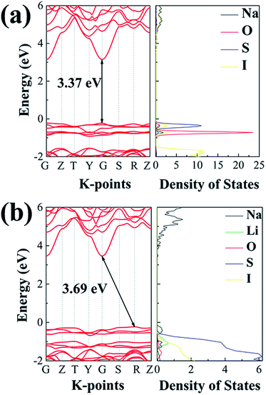 | ||
| Fig. 11 The projected density of states calculated using the HSE06 functional: (a) Na4S0.5O0.5I2; (b) Na3LiS0.5O0.5I2. | ||
Conclusions
Systematic modelling has been carried out to design fast Na+ ion conductors through optimizing materials chemistry over lattice sites of a layered anti-perovskite like structure, Na4OI2. This results in the discovery of a superb solid electrolyte Na3LiS0.5O0.5I2, which exerts extremely low activation energy for Na+ diffusion, thus permitting a room temperature Na+ conductivity of over 6.3 mS cm−1.The optimized electrolyte is compatible with the sodium anode both thermodynamically and electrochemically. Depletion of sodium at elevated voltages leads to formation of stable compounds suitable for compatible cathode materials. This enables construction of high capacity full batteries based on graded layers covering electrolyte and cathodes. The theoretical energy density for a graded battery is over 320 W h kg−1, which is fundamental for high performance solid sodium ion batteries.
Conflicts of interest
There are no conflicts to declare.Acknowledgements
This work is supported in part by the Zhengzhou Materials Genome Institute, the National Natural Science Foundation of China (No. 51001091, 111174256, 91233101, 51602094, 51602290, 11274100), and the Fundamental Research Program from the Ministry of Science and Technology of China (no. 2014CB931704).Notes and references
- M. Armand and J. M. Tarascon, Nature, 2008, 451, 652–657 CrossRef CAS PubMed.
- B. Dunn, H. Kamath and J. M. Tarascon, Science, 2011, 334, 928–935 CrossRef CAS PubMed.
- B. Scrosati, J. Hassoun and Y.-K. Sun, Energy Environ. Sci., 2011, 4, 3287–3295 RSC.
- V. Palomares, P. Serras, I. Villaluenga, K. B. Hueso, J. Carretero-González and T. Rojo, Energy Environ. Sci., 2012, 5, 5884–5901 RSC.
- A. Eftekhari, J. Power Sources, 2004, 126, 221–228 CrossRef CAS.
- X. Fan, R. R. Gaddam, N. A. Kumar and X. S. Zhao, Adv. Energy Mater., 2017, 7, 1700317 CrossRef.
- Z. Wang and G. Shao, J. Mater. Chem. A, 2018, 6, 6830–6839 RSC.
- L. Zhang, L. Chen, X. Zhou and Z. Liu, Adv. Energy Mater., 2015, 5, 1400930 CrossRef.
- N. Nitta, F. Wu, J. T. Lee and G. Yushin, Mater. Today, 2015, 18, 252–264 CrossRef CAS.
- M. Tatsumisago, M. Nagao and A. Hayashi, J. Asian Ceram. Soc., 2013, 1, 17–25 CrossRef.
- K. Takada, Acta Mater., 2013, 61, 759–770 CrossRef CAS.
- Q. Wang, P. Ping, X. Zhao, G. Chu, J. Sun and C. Chen, J. Power Sources, 2012, 208, 210–224 CrossRef CAS.
- C. Julien and G. A. Nazri, Solid State Batteries: Materials Design and Optimization, Springer US, 1994 Search PubMed.
- Y. Lu, L. Li, Q. Zhang, Z. Niu and J. Chen, Joule, 2018, 2, 1–24 CrossRef.
- J. Y. Hwang, S. T. Myung and Y. K. Sun, Chem. Soc. Rev., 2017, 46, 3529–3614 RSC.
- Y. Yu, Z. Wang and G. Shao, J. Mater. Chem. A, 2018, 6, 19843–19852 RSC.
- A. Kuhn, V. Duppel and B. V. Lotsch, Energy Environ. Sci., 2013, 6, 3548–3552 RSC.
- Z. Wang and G. Shao, J. Mater. Chem. A, 2017, 5, 21846–21857 RSC.
- W. D. Richards, T. Tsujimura, L. J. Miara, Y. Wang, J. C. Kim, S. P. Ong, I. Uechi, N. Suzuki and G. Ceder, Nat. Commun., 2016, 7, 11009 CrossRef CAS PubMed.
- Z. Zhang, E. Ramos, F. Lalère, A. Assoud, K. Kaup, P. Hartman and L. F. Nazar, Energy Environ. Sci., 2018, 11, 87–93 RSC.
- S. Wenzel, S. Randau, T. Leichtweiß, D. A. Weber, J. Sann, W. G. Zeier and J. Janek, Chem. Mater., 2016, 28, 2400–2407 CrossRef CAS.
- A. Hayashi, K. Noi, N. Tanibata, M. Nagao and M. Tatsumisago, J. Power Sources, 2014, 258, 420–423 CrossRef CAS.
- A. Hayashi, K. Noi, A. Sakuda and M. Tatsumisago, Nat. Commun., 2012, 3, 856 CrossRef PubMed.
- S.-H. Bo, Y. Wang, J. C. Kim, W. D. Richards and G. Ceder, Chem. Mater., 2016, 28, 252–258 CrossRef CAS.
- L. Zhang, K. Yang, J. Mi, L. Lu, L. Zhao, L. Wang, Y. Li and H. Zeng, Adv. Energy Mater., 2015, 5, 1501294 CrossRef.
- H. Wang, Y. Chen, Z. D. Hood, G. Sahu, A. S. Pandian, J. K. Keum, K. An and C. Liang, Angew. Chem., 2016, 128, 8693–8697 CrossRef.
- A. Banerjee, K. H. Park, J. W. Heo, Y. J. Nam, C. K. Moon, S. M. Oh, S. T. Hong and Y. S. Jung, Angew. Chem., 2016, 128, 9634–9638 CrossRef PubMed.
- Y. Zhu, X. He and Y. Mo, ACS Appl. Mater. Interfaces, 2015, 7, 23685–23693 CrossRef CAS PubMed.
- Y. Wang, Q. Wang, Z. Liu, Z. Zhou, S. Li, J. Zhu, R. Zou, Y. Wang, J. Lin and Y. Zhao, J. Power Sources, 2015, 293, 735–740 CrossRef CAS.
- H. Sabrowsky, K. Hippler, S. Sitta, P. Vogt and L. Walz, Acta Crystallogr., 1990, 46, 368–369 Search PubMed.
- H. Sabrowsky, K. Hippler and P. Vogt, Z. Naturforsch., B: J. Chem. Sci., 1989, 44, 373–374 CAS.
- J. Zhu, Y. Wang, S. Li, J. W. Howard, J. Neuefeind, Y. Ren, H. Wang, C. Liang, W. Yang, R. Zou, C. Jin and Y. Zhao, Inorg. Chem., 2016, 55, 5993–5998 CrossRef CAS PubMed.
- Z. Wang, H. Xu, M. Xuan and G. Shao, J. Mater. Chem. A, 2018, 6, 73–83 RSC.
- Z. Wang, B. Lei, X. Xia, Z. Huang, K. P. Homewood and Y. Gao, J. Phys. Chem. C, 2018, 122, 2589–2595 CrossRef CAS.
- M. Xuan, W. Xiao, H. Xu, Y. Shen, Z. Li, S. Zhang, Z. Wang and G. Shao, J. Mater. Chem. A, 2018, 6, 19231–19240 RSC.
- G. Kresse and J. Hafner, Phys. Rev. B: Condens. Matter Mater. Phys., 1993, 47, 558–561 CrossRef CAS.
- G. Kresse and J. Hafner, Phys. Rev. B: Condens. Matter Mater. Phys., 1994, 49, 14251–14269 CrossRef CAS.
- P. E. Blöchl, Phys. Rev. B: Condens. Matter Mater. Phys., 1994, 50, 17953–17979 CrossRef.
- G. Kresse and D. Joubert, Phys. Rev. B: Condens. Matter Mater. Phys., 1999, 59, 1758–1775 CrossRef CAS.
- G. Kresse and J. Hafner, Phys. Rev. B: Condens. Matter Mater. Phys., 1993, 48, 13115–13118 CrossRef CAS.
- J. P. Perdew, K. Burke and M. Ernzerhof, Phys. Rev. Lett., 1996, 77, 3865–3868 CrossRef CAS PubMed.
- G. Shao, J. Phys. Chem. C, 2009, 113, 6800–6808 CrossRef CAS.
- G. Shao, J. Phys. Chem. C, 2008, 112, 18677–18685 CrossRef CAS.
- X. Han, K. Song, L. Lu, Q. Deng, X. Xia and G. Shao, J. Mater. Chem. C, 2013, 1, 3736–3746 RSC.
- X. Han and G. Shao, J. Mater. Chem. C, 2015, 3, 530–537 RSC.
- J. Heyd, G. E. Scuseria and M. Ernzerhof, J. Chem. Phys., 2003, 118, 8207–8215 CrossRef CAS.
- J. Heyd, G. E. Scuseria and M. Ernzerhof, J. Chem. Phys., 2006, 124, 219906 CrossRef.
- A. R. Oganov and C. W. Glass, J. Chem. Phys., 2006, 124, 244704 CrossRef PubMed.
- C. W. Glass, A. R. Oganov and N. Hansen, Comput. Phys. Commun., 2006, 175, 713–720 CrossRef CAS.
- K. Parlinski, Z. Q. Li and Y. Kawazoe, Phys. Rev. Lett., 1997, 78, 4063–4066 CrossRef CAS.
- A. Togo, F. Oba and I. Tanaka, Phys. Rev. B: Condens. Matter Mater. Phys., 2008, 78, 134106 CrossRef.
- T. D. Huan, V. N. Tuoc and N. V. Minh, Phys. Rev. B, 2016, 93, 094105 CrossRef.
- F. Brivio, J. M. Frost, J. M. Skelton, A. J. Jackson, O. J. Weber, M. T. Weller, A. R. Goñi, A. M. A. Leguy, P. R. F. Barnes and A. Walsh, Phys. Rev. B: Condens. Matter Mater. Phys., 2015, 92, 144308 CrossRef.
- Z. Deng, Z. Zhu, I.-H. Chu and S. P. Ong, Chem. Mater., 2017, 29, 281–288 CrossRef CAS.
- M. V. Agnihotri, S. H. Chen, C. Beck and S. J. Singer, J. Phys. Chem. B, 2014, 118, 8170–8178 CrossRef CAS PubMed.
- X. Zhao, Z. Zhang, X. Zhang, B. Tang, Z. Xie and Z. Zhou, J. Mater. Chem. A, 2018, 6, 2625–2631 RSC.
- G. L. W. Hart and R. W. Forcade, Phys. Rev. B: Condens. Matter Mater. Phys., 2008, 77, 224115 CrossRef.
- A. V. D. Walle and G. Ceder, J. Phase Equilib., 2002, 23, 348–359 CrossRef.
- S. P. Ong, Y. Mo, W. D. Richards, L. Miara, H. S. Lee and G. Ceder, Energy Environ. Sci., 2013, 6, 148–156 RSC.
- M. H. Braga, J. A. Ferreira, V. Stockhausen, J. E. Oliveira and A. El-Azab, J. Mater. Chem. A, 2014, 2, 5470–5480 RSC.
- Y. Zhu, X. He and Y. Mo, J. Mater. Chem. A, 2016, 4, 3253–3266 RSC.
- C. Liang, D. Zhao, Y. Li, X. Li, S. Peng, G. Shao and G. Xing, Energy Environ. Mater., 2018, 1, 221–231 CrossRef CAS.
- T. Takeguchi, T. Yamanaka, H. Takahashi, H. Watanabe, T. Kuroki, H. Nakanishi, Y. Orikasa, Y. Uchimoto, H. Takano, N. Ohguri, M. Matsuda, T. Murota, K. Uosaki and W. Ueda, J. Am. Chem. Soc., 2013, 135, 11125–11130 CrossRef CAS PubMed.
- R. E. Schaak and T. E. Mallouk, Chem. Mater., 2002, 14, 1455–1471 CrossRef CAS.
- Y. Zhang, Y. Zhao and C. Chen, Phys. Rev. B: Condens. Matter Mater. Phys., 2013, 87, 134303 CrossRef.
- Q. Huang, J. Liu, S. Xu, P. Wang, D. G. Ivey, B. Huang and W. Wei, Chem. Mater., 2018, 30, 4728–4737 CrossRef CAS.
- K. Du, J. Zhu, G. Hu, H. Gao, Y. Li and J. B. Goodenough, Energy Environ. Sci., 2016, 9, 2575–2577 RSC.
- Y. Tian, T. Shi, W. D. Richards, J. Li, J. C. Kim, S.-H. Bo and G. Ceder, Energy Environ. Sci., 2017, 10, 1150–1166 RSC.
- Y. Tian, Y. Sun, D. C. Hannah, Y. Xiao, H. Liu, K. W. Chapman, S.-H. Bo and G. Ceder, Joule, 2019 DOI:10.1016/j.joule.2018.12.019.
- H. Xu, Y. Yu, Z. Wang and G. Shao, J. Mater. Chem. A, 2019, 7, 5239–5247 RSC.
- J. Liu, Z. Lu, M. B. Effat and F. Ciucci, J. Power Sources, 2019, 409, 94–101 CrossRef CAS.
Footnote |
| † Electronic supplementary information (ESI) available. See DOI: 10.1039/c9ta02166c |
| This journal is © The Royal Society of Chemistry 2019 |

