
 Open Access Article
 This Open Access Article is licensed under a
 Creative Commons Attribution 3.0 Unported Licence
Understanding the Li-ion storage mechanism in a carbon composited zinc sulfide electrode†
Guiying
Tian‡
 a,
Zijian
Zhao‡
a,
Angelina
Sarapulova
a,
Chittaranjan
Das
a,
Lihua
Zhu
a,
Suya
Liu
bc,
Aleksandr
Missiul
d,
Edmund
Welter
e,
Julia
Maibach
a and
Sonia
Dsoke
*af
a,
Zijian
Zhao‡
a,
Angelina
Sarapulova
a,
Chittaranjan
Das
a,
Lihua
Zhu
a,
Suya
Liu
bc,
Aleksandr
Missiul
d,
Edmund
Welter
e,
Julia
Maibach
a and
Sonia
Dsoke
*af
aInstitute for Applied Materials (IAM), Karlsruhe Institute of Technology (KIT), Hermann-von-Helmholtz-Platz 1, 76344 Eggenstein-Leopoldshafen, Germany. E-mail: sonia.dsoke@kit.edu
bInternational Center for New-Structured Materials (ICNSM), Zhejiang University (ZJU), Zheda Rd 38, Hangzhou, 310027, P. R. China
cInstitute of Nanotechnology (INT), Karlsruhe Institute of Technology (KIT), Hermann-von-Helmholtz-Platz 1, 76344 Eggenstein-Leopoldshafen, Germany
dCELLS-ALBA, Carrer de la Llum 2-26, 08290 Cerdanyola del Vallès, Barcelona, Spain
eDeutsches Elektronen-Synchrotron DESY, Notkestrasse 85, D-22607 Hamburg, Germany
fHelmholtz-Institute Ulm for Electrochemical Energy Storage (HIU), Helmholtzstrasse 11, 89081 Ulm, Germany
First published on 6th April 2019
Abstract
Sulfide compounds are interesting conversion electrode materials for Li-ion batteries, due to their high theoretical capacity. However, they suffer from large volumetric changes and fast capacity fading. To overcome these issues, nanosized zinc sulfide (ZnS) modified with polyelectrolytes and graphene (ZnS-C/G) has been synthesized and investigated as an enhanced conversion-alloying anode material. In situ synchrotron X-ray diffraction and X-ray absorption spectroscopy are used to elucidate the Li storage process during the 1st cycle. In addition, the evolution of internal resistance and the corresponding solid electrolyte interphase (SEI) formation during the 1st cycle are discussed based on electrochemical impedance spectroscopy and X-ray photoelectron spectroscopy. The results reveal that the formation of lithiated products and the SEI layer at different voltages can influence Li+ diffusion into the electrode. Moreover, an artificial carbon layer can not only facilitate Li+ transport but also avoid the direct formation of the SEI layer on the surface of active particles. Compared to bare ZnS, the ZnS-C/G electrode shows outstanding rate capability and cycling capacity (571 mA h g−1 after 120 cycles at a specific current of 1.0 A g−1 with a retention rate of 94.4%). The high capacity at elevated current density is ascribed to the contribution of capacitive charge storage.
1 Introduction
Green energy production/storage is very important to a sustainable society. To reduce the excessive consumption of fossil fuels and to satisfy the energy request of portable devices, there is a tremendous push towards the development of high-performance batteries. Since the initial commercialization of Li ion batteries (LIBs, e.g., LiCoO2|carbon) by Sony in 1991, the demand for LIBs has continuously increased due to the flourishing market of laptops, cell phones, cameras, grid energy storage, and especially electric vehicles.1–4 In this regard, the exploration of electrode materials, offering high specific capacity, high power density, high cycling stability, low cost and low toxicity, is an eternal target for LIBs. Beyond the conventional graphite anode, conversion-type materials as high capacity anodes for LIBs are gaining increasing attention.5In general, sulfur atoms possess a large atomic radius and they are easily polarized.6 Metal–sulfur bonds in sulfide conversion materials are more easily broken/formed during the electrochemical Li+ insertion/deinsertion compared to metal–oxygen bonds. Thus, they effectively enhance the reaction kinetics and decrease the overpotential for lithium storage.7 In the conversion reaction, the transition metal can be fully and reversibly reduced to its metallic state, leading to high theoretical capacity.7–11 Thus, many sulfide conversion materials (e.g., FeS2, NiS, CoS2, MnS, MoS2, and ZnS) have been studied as anode materials for LIBs.12–17 Differing from other transition-metals, lithium storage in the ZnS electrode relies not only on the redox conversion mechanism but also on the alloying mechanism. The formation of a Zn–Li alloy leads to a higher theoretical capacity (824.9 mA h g−1), compared to the one only based on the conversion mechanism (549.9 mA g−1). In addition, since ZnS is the main form of zinc which can be found in the nature (as sphalerite and wurtzite), it can be used as low-cost electrode material.
Based on the conversion mechanism, the lithiation process leads to the formation of nanosized metal grains embedded in amorphous Li2S. Due to the large amount of Li+ ions being inserted/deinserted, conversion materials undergo significant volumetric expansion, leading to pulverization during cycling. The reconstructive phase transition can also cause dissolution of polysulfide intermediates in an organic electrolyte, when sulfide anodes are directly exposed to the electrolyte.17 Thus, the problems of poor cycling stability and rapid capacity fading are unavoidable for sulfide anodes. At the same time, the low electronic conductivity of ZnS severely restricts the electrochemical kinetics. To solve these issues, carbon modification was proposed to enhance the bulk conductivity and cycling stability.7,13 Most importantly, carbon modification can further improve the structural stability by capturing/adsorbing polysulfide intermediates.18,19 However, there is still a need to elucidate the structural evolution and electrochemical kinetics of sulfide-type conversion materials with a carbon coating during the cycling process.
Currently, many efforts are focused on the development of conversion materials with novel synthesis techniques to create unique morphologies and achieve excellent performance.15,20–25 However, only a few studies have provided an understanding of the detailed reaction mechanism, such as phase transitions and resistance changes. Thus, the crystal change and SEI formation during the electrochemical reaction need to be further investigated.26 In this study, ZnS nanoparticles modified with a carbon coating derived from polyelectrolytes and graphene (ZnS-C/G) are studied as a typical conversion-alloying electrode material. The electrochemical performance, evolution of the crystal phase and simultaneous SEI formation are analysed systematically using a series of in situ and ex situ methods (synchrotron radiation diffraction (SRD), X-ray absorption spectroscopy (XAS), X-ray photoelectron spectroscopy (XPS) and electrochemical impedance spectroscopy (EIS)).
2 Experimental
2.1 Synthesis of ZnS via a precipitation method
The ZnS sample was prepared via a facile precipitation method. ZnSO4·6H2O (purity ≥ 99.0%, Acros) and thioacetimidic acid (TAA, C2H5NS, purity ≥ 99.0%, Sigma-Aldrich) were used without further purification. The zinc salt was first dissolved in deionized water to form a 0.4 M solution, and then several drops of ammonium hydroxide aqueous solution (28% NH3 in H2O, ≥99.99% trace metals basis, Sigma-Aldrich) were added to adjust the pH value to around 9. Afterwards, 10 wt% TAA diluted aqueous solution (S![[thin space (1/6-em)]](https://www.rsc.org/images/entities/char_2009.gif) :Zn = 1.2:1 in molar ratio) was added dropwise into the boiling Zn2+ solution while stirring at 1000 rpm. The obtained sediment was then washed and centrifuged several times with deionized water and ethanol. Finally, a white sample (denoted as ZnS) was obtained after a drying step at 80 °C for 12 h and a calcination treatment at 500 °C for 3 h under an Ar flow.
:Zn = 1.2:1 in molar ratio) was added dropwise into the boiling Zn2+ solution while stirring at 1000 rpm. The obtained sediment was then washed and centrifuged several times with deionized water and ethanol. Finally, a white sample (denoted as ZnS) was obtained after a drying step at 80 °C for 12 h and a calcination treatment at 500 °C for 3 h under an Ar flow.
2.2 Carbon coating via electrostatic self-bonding
Based on the electrostatic self-bonding method,27 0.40 g ZnS sediment without calcination was dispersed in 100 mL deionized water by stirring at 600 rpm. After that, 2.50 g poly(diallyldimethylammonium chloride) (PDDA, 20 wt%, Mw < 500000 Da, Aldrich) was added into the suspension. In addition, a graphene suspension was prepared by dispersing 0.05 g graphene (Inner Mongolia Dasheng Co., Ltd) and 1.67 g poly(sodium-4-styrenesulfonate) (PSS, 30 wt%, Mw < 70000 Da, Aldrich) in deionized water stirred at 600 rpm. The two suspensions with oppositely charged polyelectrolytes were then mixed under vigorous magnetic stirring homogeneously. A cream-like sediment was achieved after washing and centrifugation. Finally, the oven-dried sample was carbonized at 500 °C for 3 h under Ar flow, denoted as ZnS-C/G.
2.3 General characterization
XRD measurements were carried out using an STOE STADI P X-ray powder diffractometer equipped with a Mythen 1K detector and Mo Kα1 radiation (λ = 0.70932 Å) in a 2θ range of 10°–50° in Debye–Scherrer geometry. Rietveld refinement was employed to analyse the diffraction data using the FullProf software package.28 To further visualize the crystalline structure, high-resolution transmission electron microscopy (HRTEM) was carried out on an aberration (image) corrected transmission electron microscope (Titan 80-300, FEI Company) using a Gatan US1000 slow-scan CCD camera. TEM samples were prepared by dispersing the sample powder into ethanol and then drop casting on copper grids (Qantifoil Inc.). A Merlin thermal field emission scanning electron microscope (SEM, Carl Zeiss SMT AG) was also employed. Energy-dispersive X-ray spectroscopy (EDX, Bruker, Quantax 400 SDD) was used to confirm the elemental composition. Raman measurements were performed on a LabRam Evolution HR instrument (HORIBA Jobin Yvon) using 632 nm laser excitation to analyse the carbide material. X-ray photoelectron spectroscopy (XPS) was performed on a K-Alpha XP spectrometer (Thermo-Fisher Scientific, East Grinstead, UK). All samples were analysed using a micro-focused, monochromated Al Kα X-ray source (400 μm spot size). The spectra are referenced in binding energy to the C 1s peak (C–C, C–H) at 284.4 eV binding energy.2.4 Electrochemical characterization
Electrodes were prepared by coating a homogeneous slurry on a piece of copper foil with an active mass loading of ∼2.0 mg cm−2. The slurry consists of the active material (70 wt%), PVDF binder (10 wt%, R6020/1001, Solvay) and carbon black (20 wt%, Super P Li, Timcal Ltd.). A typical CR2032 coin cell consists of a working electrode (ϕ 12 mm), a microporous separator (ϕ 16 mm, Celgard 2325-1750-A), lithium foil (ϕ 15 mm, Alfa Aesar) as the counter electrode and 180 μL of LP30 electrolyte (1 M LiPF6 in ethylene carbonate/dimethyl carbonate = 1:1 by volume ratio, BASF). All cells were assembled in an argon-filled glovebox (MB200, MBraun GmbH). Galvanostatic cycling, cyclic voltammetry (CV) and electrochemical impedance spectroscopy (EIS) were carried out using a multichannel potentiostat (VMP3, Bio-Logic). The galvanostatic cycling and CV test were performed in a potential range of 3.0–0.01 V vs. Li/Li+. The test cells were kept inside a climate chamber (Binder) at 25 °C during the experiments. The calculation of the specific capacity of the ZnS-C/G is based on its total mass of loaded carbon and ZnS bulk.
A three-electrode EL-CELL® was built for EIS tests with a working electrode, a thin glass fiber separator, a lithium foil counter electrode, LP30 electrolyte, and a Li-ring reference electrode placed exactly around the working and counter electrodes. This cell was cycled with potential steps of ±0.185 V in the voltage range of open-circuit voltage (OCV) → 0.01 V → 3.00 V. At each potential, the cell was held for 3 h for charge equilibrium followed by the EIS test using an alternating current signal of a small amplitude of 5 mV over a frequency range from 500 kHz to 10 mHz.
2.5 In situ structural characterization
The electrodes for in situ tests were prepared by mixing 70 wt% of active material, 20 wt% of carbon black (Super P Li, Timcal Ltd.) and 10 wt% of polytetrafluoroethylene (PTFE beads, Aldrich). The dry mixture was well ground with a mortar and pestle. About 3.5 mg of this mixture was pressed on the centre of a copper mesh disc (ϕ 12 mm) and dried in a vacuum oven at 80 °C for 12 h. CR2025 coin cells (Li|LP30|ZnS) with glass windows were assembled by using the same method as stated above.In situ synchrotron radiation diffraction (SRD) data were collected using synchrotron radiation (λ = 0.41266(2) Å) at the materials science and powder diffraction beamline (MSPD), ALBA, Barcelona (see Fig. S1†). During the in situ measurements, the cells were cycled at 80 mA g−1 in the potential range of 0.01–3.0 V vs. Li/Li+ at room temperature, and Si and LaB6 were used as standard samples for calibration. In situ XAS measurements were performed at the P65 beamline (photon flux > 1011 to 1012 s−1) at PETRA III in DESY, Hamburg (see Fig. S2†).
In situ XAS spectra were recorded in transmission geometry with the conventional step-scan mode at the Zn K-edge (9659 eV). The double-crystal fixed exit monochromator equipped with a Si (111) crystal and the ionization chamber were optimized for the Zn edge. The cells were cycled at 150 mA g−1 in the potential range from OCV to 0.01 V vs. Li/Li+ at room temperature using a VMP3 potentiostat (Bio-Logic), which was taken from the P02.1 beam line (PETRA III, DESY, Hamburg). The spectra were processed using the Demeter software package.29
3 Results and discussion
3.1 Synthesis and characterization
In this study, the ZnS precursor was synthesized via the simple precipitation method. In boiling water, TAA decomposes and releases free sulfur (S2−), which interacts with Zn2+ in a weakly alkaline environment forming the white precursor. Afterwards, the ZnS precursor was mixed with graphene via the strong electrostatic self-bonding of polyelectrolytes with positive/negative charges. Graphene-based composites have been intensively studied in energy storage applications due to their unique properties, including high conductivity and excellent mechanical strength.30–32 Both graphene and polyelectrolytes serve as the carbon source to cover/contact the ZnS particles, as schematically illustrated in Fig. 1a. Finally, the black ZnS-C/G composite was obtained after the pyrolysis process. For comparison, the pristine ZnS sample, prepared without carbon modification, was also synthesized in the same way. Fig. 1b shows the morphology of the graphene, and some corrugations and scrolls in the graphene sheets can be seen, indicating the ultrathin laminated structure. The morphology of ZnS is shown in Fig. 1c, where one can observe that its secondary particles are a cluster of primary nanoparticles (∼10 nm) stacked together, and this is confirmed by TEM later. The ZnS-C/G composite possesses a similar morphology to ZnS particles (Fig. 1d). To further verify the homogeneity of the ZnS-C/G composite, EDX elemental mapping was performed and the results are shown in Fig. 1e–h. Zinc and sulfur are co-located on the elliptical shapes, and carbon is randomly distributed, indicating that carbon is already effectively coated on the surface of ZnS particles.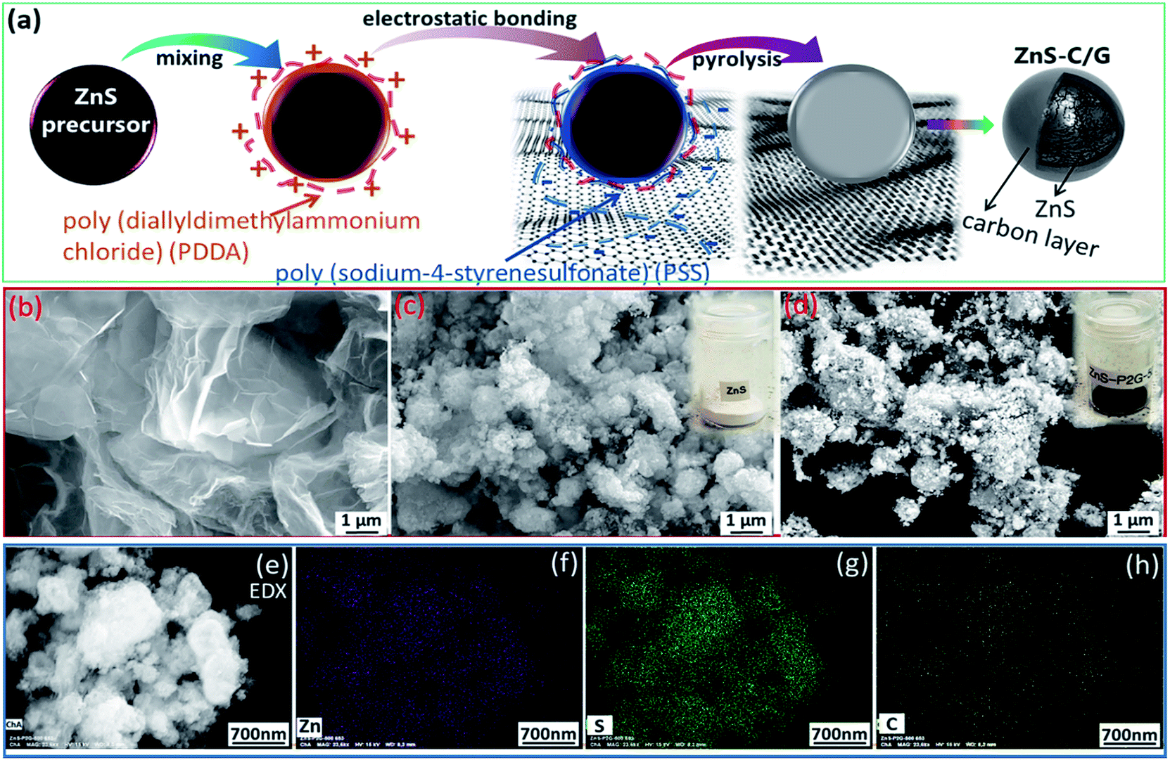 | ||
| Fig. 1 (a) Schematic illustration of the synthesis method of the ZnS-C/G; SEM images of (b) graphene, (c) ZnS, and (d) ZnS-C/G; and (e–h) SEM and corresponding elemental mapping images of the ZnS-C/G (Zn, S and C, respectively). | ||
HRTEM images are collected to further confirm the carbon coated ZnS-C/G composite. The HRTEM image in Fig. 2a shows that nanosized ZnS particles are homogeneously covered by an ∼2 nm carbon layer. The inserted image provides a detailed view of crystal lattice fringes of ZnS with a spacing of 0.307 nm, which corresponds to the (111) lattice planes. Furthermore, the phase purity of the ZnS-C/G composite is evaluated based on the XRD pattern using Rietveld refinement of the structure model. In Fig. 2b, the refinement confirms that the main reflections are well indexed to the ZnS cubic phase (space group: F![[4 with combining macron]](https://www.rsc.org/images/entities/char_0034_0304.gif) 3m). Satisfactory agreement factors (Rwp = 4.78% and Rp = 6.20%) with the cell parameters (a = b = c = 5.399(2) Å and cell volume = 157.4(1) Å3) are determined in this crystal structure refinement.
3m). Satisfactory agreement factors (Rwp = 4.78% and Rp = 6.20%) with the cell parameters (a = b = c = 5.399(2) Å and cell volume = 157.4(1) Å3) are determined in this crystal structure refinement.
 | ||
| Fig. 2 (a) HRTEM images of the ZnS-C/G composite; (b) Rietveld refinement of the structure model, based on the XRD pattern of the ZnS-C/G composite. | ||
As discussed above, carbon coating is an effective strategy to improve the bulk conductivity of conversion-type electrodes. To determine the degree of graphitization of the coated carbon, Raman measurements of ZnS and the ZnS-C/G were carried out. As presented in Fig. S3a,† ZnS displays a series of modes at 259.4, 347.7 and 700.4 cm−1, corresponding to the longitudinal optical (LO) phonon–plasmon coupled L− mode, the LO phonon mode associated with the Brillouin zone center, and the E1(LO) mode at Γ.33–35 Together with the XRD refined result, Raman analysis confirms that ZnS is a single cubic phase. In contrast, the typical ZnS modes are not observed in the ZnS-C/G, due to the uniform carbon coating. The intensity ratio of G (graphitic) and D (defective) bands (IG/ID) can be used to determine the graphitization level of coated carbon. A higher IG/ID ratio corresponds to a higher degree of graphitization. Here, the IG/ID ratio of ∼0.62 for the ZnS-C/G is higher than the threshold (0.52) for electron-conductive carbon,36,37 indicating that the surface of the ZnS nanoparticles is wrapped with a conductive carbon layer.
3.2 Electrochemical mechanism
To evaluate the effect of carbon coating modification, CV and galvanostatic cycling tests were performed over a potential range of 3.0–0.01 V vs. Li/Li+ on the uncoated and coated ZnS. As presented in the 1st CV curve (Fig. 3a), the current drops rapidly at 0.5 V during the first cathodic scan, that corresponds to an activation process due to the initial reduction of ZnS to Zn (or LixZn), and initial formation of the solid electrolyte interphase (SEI), resulting in a large amount of Li+ consumption.38,39 In this study, the origin of these peaks will be discussed later based on EIS and ex situ XPS analysis. In the anodic scans, it is noteworthy that a series of peaks at 0.27 V, 0.35 V, 0.57 V, and 0.71 V are present. The peaks are ascribed to multiple steps of the dealloying process (LiZn → Li2Zn3 → LiZn2 → Li2Zn5 → LiZn4).40–42 After the 1st lithiation, the main reduction peak at ∼0.6 V in the cathodic scan and main oxidation peak at ∼1.3 V in the anodic scan can be assigned to the desulfidation to zinc and resulfidation to ZnS, respectively. These main redox peaks in the CV curves fade gradually, indicating the unstable structure of bare ZnS. In the galvanostatic cycling, bare ZnS displays high irreversible capacity at the 1st cycle (910 mA h g−1), and a fast capacity fade in the following cycles (from 2100 mA h g−1 at the 1st cycle to 1190 mA h g−1 at the 2nd cycle, and 650 mA h g−1 at the 10th cycle, see Fig. 3c).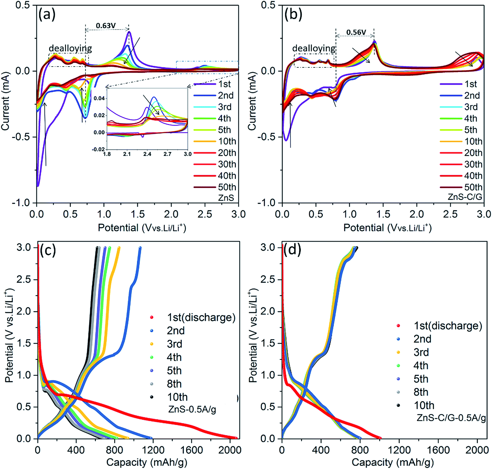 | ||
| Fig. 3 CV curves of the 1st to 50th cycles at a scan rate of 0.1 mV s−1: (a) ZnS and (b) ZnS-C/G; galvanostatic cycling profiles of the 1st to 10th cycles at a current density of 0.5 A g−1: (c) ZnS and (d) ZnS-C/G. | ||
The CV scans of the carbon-coated ZnS-C/G material show in principle the same anodic and cathodic peaks as the uncoated material. However, the fade of the redox peaks is much less, indicating improved structural and electrochemical stability of the ZnS-C/G electrode (see Fig. 3b). In addition, the polarization of the ZnS-C/G electrode is reduced to 0.56 V compared to that of bare ZnS (0.63 V), which is ascribed to the improvement of the bulk conductivity of the ZnS-C/G electrode via the carbon coating. The improved reversibility of the ZnS-C/G electrode can also be viewed on the consecutive galvanostatic cycling (Fig. 3d). The irreversible capacity at the 1st cycle (213 mA h g−1) is much lower than that of ZnS (910 mA h g−1), indicating that fewer Li+ ions are consumed in this irreversible SEI formation.43 This can indicate that the carbon coating acts as a protection shell on the ZnS particles preventing SEI formation directly on the ZnS particles. In addition, the ZnS-C/G electrode maintains high capacity during the subsequent cycles (800 mA h g−1 at the 2nd cycle and 780 mA h g−1 at the 10th cycle). These electrochemical results suggest that it is promising to achieve long-term reversible cycling with the ZnS-C/G material.
In order to further determine the mechanism of the electrochemical reaction, in situ SRD analysis was performed. Fig. 4a shows the initial galvanostatic cycle of the ZnS-C/G electrode vs. lithium foil in a voltage range of 0.01–3.0 V. The corresponding SRD patterns (Fig. S4a and b†), consecutively recorded with 133 scans, provide an overview of the structural evolution. To clarify the multiple steps during (de)lithiation processes, the procedure is divided into four steps (steps I–IV).
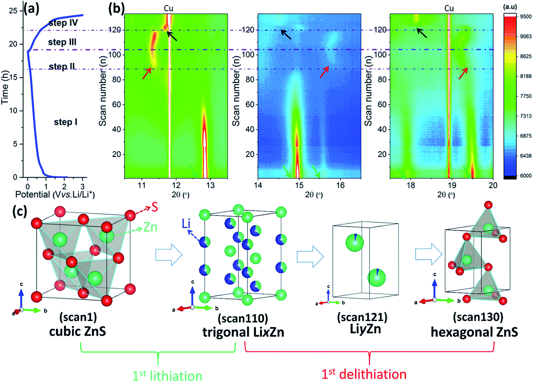 | ||
| Fig. 4 In situ SRD analysis of the ZnS-C/G electrode during the 1st cycle: (a) the galvanostatic cycling profile at a current density of 80 mA g−1, (b) contour plots of the SRD patterns, and (c) the typical phase evolution of the ZnS-C/G electrode. | ||
In step I (scan 1–scan 84, 2.37–0.21 V), Fig. 4b and S5a† show that the ordered cubic structure of ZnS is still maintained at the beginning of the lithiation process, and Rietveld refinement determines the cubic structure of scan 20 at 0.86 V (space group: F3m, see Fig. S5b†); and further lithiation can reduce the content of the cubic structure, as confirmed by the gradually decreased intensity corresponding to the ZnS cubic phase (marked with green arrows). At the same time, a gently sloping voltage profile around 0.4 V can be observed in step I, confirming that a large number of Li+ ions are consumed or stored here, which is due to the initial conversion reaction, SEI formation and pseudocapacitive storage. Therefore, no new phase related to conversion products (i.e., reduced Zn and Li2S) appears here. This is also possible because the particle size of the formed Zn grains is below a few nanometers, and the amorphous Li2S cannot be seen in the SRD pattern either.
In step II (scan 85–scan 104, 0.21–0.01 V), new reflections at about 11.1°, 15.7° and 19.4° (marked with red arrows) start to appear since scan 85 (see Fig. 4b and S5c†). The previously formed Zn starts to alloy with Li+ ions, forming a LixZn alloy with a low x value (x ≈ 0). A refined analysis of scan 110 confirms the trigonal crystal structure (space group: P![[3 with combining macron]](https://www.rsc.org/images/entities/char_0033_0304.gif) m1) of Li0.62Zn0.87 (Li0.71Zn), indicating further lithiation and formation of the LixZn alloy with increasing x value (see Fig. S5d†). The higher lithiation level leads to a gradual shift of the reflections towards lower 2θ angles, because inserted Li+ ions expand the unit cell of LixZn, which was also observed in the lithiation process of ZnO.40 When delithiation is performed from scan 105 to scan 120, the reflections shift back to higher 2θ angles (step III, 0.01–0.89 V), and this phenomenon corresponds to the dealloying process.
m1) of Li0.62Zn0.87 (Li0.71Zn), indicating further lithiation and formation of the LixZn alloy with increasing x value (see Fig. S5d†). The higher lithiation level leads to a gradual shift of the reflections towards lower 2θ angles, because inserted Li+ ions expand the unit cell of LixZn, which was also observed in the lithiation process of ZnO.40 When delithiation is performed from scan 105 to scan 120, the reflections shift back to higher 2θ angles (step III, 0.01–0.89 V), and this phenomenon corresponds to the dealloying process.
In step IV (scan 121–scan 133, 0.89–3.00 V), Fig. 4b shows that a new phase appears (marked with black arrows). This is related to the formation of a LiyZn alloy with a low y value during the dealloying process.40 The SRD patterns of scan 121 are compared with references (Fig. S5e, f and S6†). This comparison proves the formation of Li0.25Zn, indicating that the y in the LiyZn alloy becomes less again. Corresponding to the last steep increase of potential, the reflections of hexagonal ZnS appear (space group: P63mc). At the same time, the LiyZn-related reflections completely vanish (see Fig. S5g†).
To further determine the evolution of the zinc species in the ZnS-C/G electrode during the 1st lithiation, in situ XAS at the Zn K-edge (9659 eV) are measured during a galvanostatic cycle performed at 150 mA g−1 from OCV to 0.05 V vs. Li/Li+ (Fig. 5a). Fig. 5b shows that the Zn K-edge of the pristine ZnS-C/G electrode systematically shifts to lower energies as the lithiation level increases, confirming the conversion reaction Zn2+ → Zn0. However, the mismatch of scan 12 and the Zn-foil reference suggests that the conversion reaction to metallic Zn does not completely finish. Zn K-edge EXAFS Fourier transform (FT) curves are plotted in Fig. 5c. The pristine ZnS-C/G shows one distinct peak at ∼1.84 Å and one broad peak at 3.4–4.1 Å, corresponding to the 1st Zn coordination shell of 4 S and overlapping of the 2nd and 3rd shells with 12 Zn and 9 S, respectively.44 As more Li+ ions are inserted and the voltage decreases to ∼0.15 V (scan 9), the three peaks become weaker and weaker, and shift to higher distances. This corresponds to step I in the in situ SRD analysis, where ZnS gradually deforms as more Li+ are inserted. The estimation of the oxidation state of Zn in the ZnS-C/G (according to reference spectra of Zn metal foil and pristine ZnS) is achieved through linear combination fitting of the Zn K-edge XANES spectra (see Table S1 and Fig. S7†). The result proves that not all Zn is involved in the conversion reaction due to the fast lithiation, and 31.6 wt% of residual ZnS still remains unreacted in the ZnS-C/G electrode (see Fig. 5d). Previous reports attempted to elucidate the electrochemical mechanism of Li-insertion in ZnS. He et al.24 for the first time used ex situ XRD patterns to confirm the formation of Zn + LixZn (1st lithiation at 0.05 V), and ZnS (1st delithiation at 2.0 V). Park et al.45 applied ex situ XRD and XAS to determine the formation of LiZn4 (1st lithiation at 0.4 V), LiZn (1st lithiation at 0.0 V) and ZnS (1st delithiation at 2.0 V). As we know, in situ technologies have the advantage to avoid the influence of external factors affecting the sensitive cycled electrolyte, and also to provide consecutive information during the (de)lithiation process. In this study, it is the first time that the (de)lithiation evolution of the ZnS electrode during the 1st cycle is elucidated in detail by in situ analysis (XRD and XAS). In situ XRD clearly shows the formed intermediate alloying phases: there is no evidence of the pure Zn phase, but of LixZn with an extremely low x value. The fitting of in situ XAS confirms the Zn generation (68.4% of total Zn source in the electrode). After the 1st cycle, hexagonal ZnS is regenerated, which is different from the initial cubic ZnS phase. The multiple processes (conversion and alloying reactions) can be described with the following reactions:
 | ||
| Fig. 5 (a) Potential profile during the 1st lithiation of the ZnS-C/G cell at a current density of 150 mA g−1; (b) normalized XAS spectra at the Zn K-edge during the 1st lithiation process; (c) Fourier transform of the recorded EXAFS-spectra; (d) Zn-containing phase compositions at varying scan numbers obtained by linear combination fitting. | ||
Step I (lithiation conversion, OCV ∼ 0.21 V):
| cubic ZnS + 2Li+ + 2e− → Li2S + Zn |
Step II (lithiation alloying, 0.21–0.01 V):
| Zn + xLi+ + xe− → trigonal LixZn |
Step III (delithiation dealloying, 0.01–0.89 V):
| LixZn → LiyZn + (x − y)e− + (x − y)Li+ (x > y) |
| LiyZn → Zn + ye− + yLi+ |
Step IV (delithiation conversion, 0.89–3.00 V):
| Li2S + Zn → hexagonal ZnS + 2e− + 2Li+ |
3.3 Study of the internal resistance evolution and SEI formation
During the lithiation process, Li+ ions are transported through the surface of the ZnS-C/G electrode, and then inserted into the bulk active material. In this respect, it is necessary to evaluate the Li+ ion diffusion process. Thus, EIS data were collected to deduce the diffusion coefficient during the 1st cycle. Fig. 6 shows the Nyquist plots obtained from the EIS test performed on an EL-CELL® with a ring-shape reference electrode (see Fig. S8a†). The cell was (de)lithiated incrementally in small potential steps, and the impedance spectra were recorded at each potential after 3 h relaxation. For the sake of simplicity, the fitted Nyquist plots in Fig. 6 are displayed in four graphs related to four steps (steps A–D). The Li+ diffusion coefficient (DLi) can be calculated according to eqn (1): 46| DLi = 0.5 × (RT/Az2F2CLiσ)2 | (1) |
485 C mol−1), CLi is the molar concentration of Li+, and σ is the Warburg coefficient obtained from the slope of Z′ vs. ω−0.5 at low frequencies (see Fig. S9†). The DLi values are summarized in Fig. 7e divided into four steps (step A–D).
 | ||
| Fig. 6 Nyquist plots obtained from the EIS test at varying potentials (the inserts are magnifications of the Nyquist plots at high-frequency): (a) lithiation 2.5–1.0 V, (b) lithiation 1.2–0.1 V, (c) delithiation 0.01–1.4 V, and (d) delithiation 1.4–3.0 V. | ||
 | ||
| Fig. 7 The fitted respective resistances as a function of cycling voltage: (a) Rel, (b) Rcon, (c) RSEI, and (d) Rct; and (e) the diffusion coefficient of the ZnS-C/G electrode calculated based on Warburg diffusion. | ||
In general, the variation of impedance and Li+ diffusion with the potential depends on interfacial changes induced by the SEI formation and phase transition caused by the redox reactions.47 To clarify this, an equivalent circuit (Fig. S8b†) has been used to fit these EIS spectra. In this equivalent circuit, Rel accounts for the contribution of the liquid electrolyte, separator and internal connections of the cell, corresponding to the intercept with the real axis at high-frequency. At high frequency, the interface resistance (Rinter) mainly consists of SEI resistance (RSEI) and contact resistance (Rcon), combined with the related double layer capacitance (Cdl1 and Cdl2). At low frequency, charge transfer resistance (Rct) combined with the related double layer capacitance (Cdl3) corresponds to the third semicircle. Also in the low frequency region, it is possible to recognize a 45° inclined line as Warburg diffusion related to Li+ diffusion into the electrode. As summarized in Fig. 7a, there is no obvious change in the Rel during the 1st cycle, which means that the liquid electrolyte is electrochemically stable.
In detail, Fig. 6a displays the spectra related to step A (related to the voltage range of 2.5 V → 1.2 V). In step A, Rct is extremely high since no lithiation reaction (no charge transfer) is observed above 1.2 V, as confirmed by the 1st CV curve in Fig. 3b. At the same time, a relatively high Rinter can be obtained in Fig. 7b due to the fresh status of the electrode. Thereafter, in step B, the semicircle size of the Rct drops rapidly from 1.2 V to 0.1 V (see Fig. 6b), and this corresponds to the cathodic peaks of the 1st CV curve at ∼0.75, ∼0.5 and ∼0.1 V (see Fig. 3b), meaning the occurrence of Li+ ion insertion into the electrode. A decrease in the Rinter can be ascribed to the SEI formation, because a thin SEI layer can facilitate Li+ to go through the interface of the active particles. Hence, the Rinter and Rct are further combined into one semicircle. The increase in Rct after lithiation at ∼0.1 V suggests that the lithiation process in the ZnS bulk finishes; the Rcon and RSEI are reduced due to the accumulation of metallic Zn and the appearance of the LixZn alloy which can increase the electrode conductivity. In step C (see Fig. 6c), the Rct decreases again at around 1.2 V due to the occurrence of delithiation.
In step D, the increase in Rinter could be ascribed to the fact that the pulverized nanograins are surrounded by the SEI layer, leading to a high resistance above 2.5 V (Fig. 6d). The increasing Rct suggests that the delithiation process ends at 1.8 V. In sum, a relatively low Rct is obtained at 0.8–0.2 V in the lithiation process and at 0.9–1.6 V in the delithiation process, in accordance with the main conversion and (de)alloying processes. Furthermore, the change of DLi can be clearly observed in Fig. 7b, where a relatively high DLi is observed from 1.0 V to 0.01 V in the lithiation process and below 1.5 V in the delithiation process. In step D, Li ions diffuse slowly again because of the reconstruction of the nonconductive ZnS. Basically, the occurrence of (de)lithiation in certain potential ranges can directly influence the variation of the Rct and the DLi.
Because the Li storage in the anode material is normally accompanied by SEI formation,42,48 XPS analysis was performed on the ZnS-C/G electrodes to uncover the SEI components involved in redox reactions (comparing a pristine electrode and lithiated electrodes at 1.0 V and 0.01 V during the 1st lithiation process). The pristine electrode and the lithiated electrode at 1.0 V show similar spectra of Zn 2p peaks at 1022.1 and 1045.3 eV, corresponding to Zn 2p3/2 and Zn 2p1/2, respectively (Fig. 8a).49 No reduction of Zn2+ → Zn0 can be observed in the XPS data above 1.0 V, while these typical Zn peaks disappear on the lithiated electrode at 0.01 V. This indicates that the surface of the active material (ZnS) is fully covered by an SEI layer when the potential is further reduced from 1.0 V to 0.01 V. This is also confirmed by the S 2p1/2 and 2p3/2 peaks (162.6 eV and 161.4 eV) observed only at the pristine and 1.0 V lithiated electrodes, corresponding to the Zn–S bonds (Fig. 8b). In contrast to Zn 2p, the S 2p still remains visible for the lithiated electrode at 0.01 V. The sulfur signal may come either from the active material underneath the SEI layer as it has higher kinetic energy compared to Zn 2p or from sulfur compounds in the SEI layer. On considering the shift due to the dipole of the SEI layer,50 the S 2p peak is found to be at the lower binding energy of 160.5 eV which indicates the formation of Li2S underneath the SEI layer during lithiation.51 However, the limited probing depth of 10 nm in XPS measurement restricts a further comment on the formation of LixZn. Compared to the Li-free pristine ZnS electrode, the peaks of Li 1s appearing at 56.0 eV for the lithiated electrode at 1.0 V and at 55.2 eV for the lithiated electrode at 0.01 V can be assigned to LiF and Li-carbonates, respectively (Fig. 8c).52
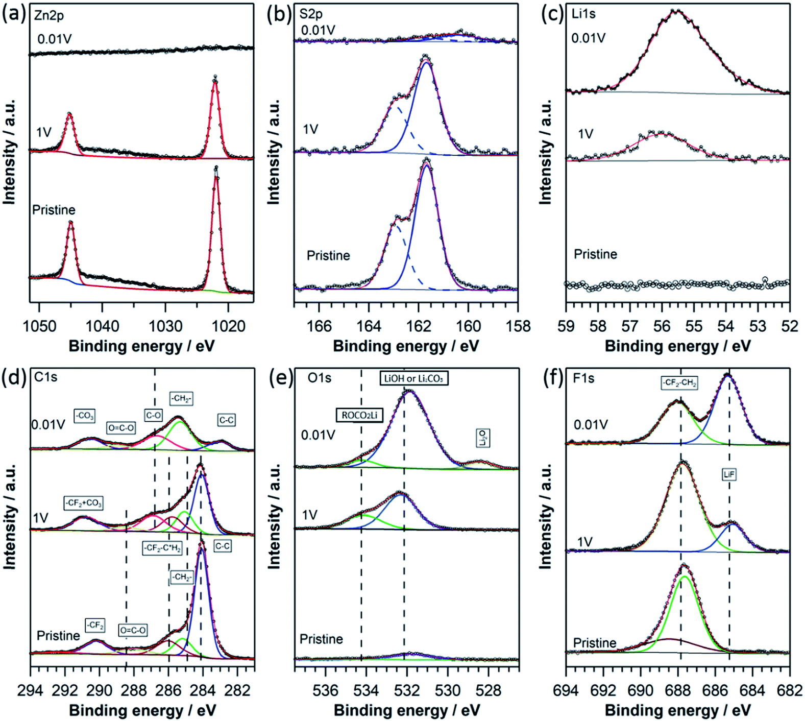 | ||
| Fig. 8 XPS spectra of ZnS-C/G electrodes at pristine, lithiated 1.0 V and 0.01 V states: Zn 2p (a), S 2p (b), Li 1s (c), C 1s (d), O 1s (e) and F 1s (f). | ||
In the carbon spectra in Fig. 8d, the high signal intensity of graphitic carbon (at 284.4 eV) is ascribed to the added carbon (i.e., Super P and graphene). The active carbon and PVDF binder can introduce some oxygen and fluorine containing groups as observed at higher binding energies in the spectrum of the pristine electrode. As lithiation proceeds, the peak intensity in the C 1s, corresponding to hydrocarbon at 285.3 eV, ester group at 286.7 eV and carbonate at 289.5/290.4 eV, gradually increases, which shows the presence of a mixture of PEO-type oligomers (–CH2–CH2–O–)n, and ROCO2Li/Li2CO3 in the SEI layer.53 The clearly reduced intensity for graphitic carbon and the absence of the Zn 2p signal at 0.01 V show that the surface of the ZnS-C/G electrode is covered with an SEI layer with a thickness of more than 5 nm, corresponding to the information depth for C 1s using Al Kα radiation. In O 1s spectra (Fig. 8e), peaks at 532.1 and 534.4 eV in both the lithiated samples are observed, which correspond to the formation of LiOH (or Li2CO3) and ROCO2Li induced by electrolyte decomposition, respectively.53–55 In addition, the O 1s spectrum of the highly lithiated sample at 0.01 V shows the formation of Li2O (at 528.2 eV) due to the further decomposition of LiOH or Li2CO3 at a low potential.56 As shown in Fig. 8f in the F 1s spectra, a peak at 687.8 eV from PVDF binder appears for all three electrodes. However, a peak at lower binding energy appears at 685.2 eV for the electrode lithiated at 1.0 V and becomes more intensive for the electrode lithiated at 0.01 V. The appearance of the lower binding energy peak in the F 1s spectra of the lithiated samples confirms the formation of LiF at the surface, which comes from the side reaction of LiPF6 (LiPF6 → LiF + PF5 or LiPF6 + xe− + xLi+ → (1 + x)LiF + LiPF6−x).57 From the XPS analysis, one can observe the formation of the SEI layer above the lithiation potential at 1.0 V, which is composed of mainly organic materials (PEO-type oligomers (–CH2–CH2–O–)n and ROCO2Li) and inorganic Li salts (Li2CO3, LiOH, LiF and Li2O), while the amount of the inorganic species obviously increases with further lithiation to lower potential (0.01 V). Although producing irreversible capacity at the 1st lithiation process, the formed SEI layer increases the wettability of the active material and the surface Li+ concentration, so that the Rcon and RSEI decrease at low potentials (≤1.5 V), and therefore facilitates the lithiation reaction.
3.4 Long-term electrochemical performance
Fig. 9a displays the rate performance at current densities varying from 0.05 to 2.0 A g−1. The ZnS-C/G electrode exhibits higher rate-capability compared to the ZnS electrode, especially at high current densities (710 vs. 487 mA h g−1 at 0.5 A g−1, and 475 vs. 304 mA h g−1 at 2.0 A g−1 for the ZnS-C/G vs. the ZnS). Notably, when the current density goes back to 0.05 A g−1, the capacity of the ZnS-C/G electrode increases to ∼1036 mA h g−1, which is even higher than the initial capacity. This is because of the increase in Li+ storage via pseudo-capacitive charge storage.43,58Fig. 9b depicts the cycling performance of the ZnS and the ZnS-C/G electrodes at a current density of 1.0 A g−1. It is noteworthy that the delithiation capacity of ZnS decreases rapidly from 910 mA h g−1 (the 1st cycle) to 214 mA h g−1 (the 80th cycle). However, the capacity of the ZnS-C/G even increases slightly from the 18th cycle (534 mA h g−1) to 120th cycle (571 mA h g−1). This is a typical electrochemical behaviour for oxide/sulfide-based conversion anodes. The increase in capacity can be attributed to the capacitive reversible Li+ storage in the SEI layer.58–60 In addition, a rise in delithiation capacity can also be observed in the bare ZnS electrode at a lower current density of 0.1 A g−1 (see Fig. S10†). However, after 120 cycles, the capacity of the ZnS-C/G electrode starts to drop but still remains as high as ca. 452 mA h g−1 at the 200th cycle, and after 150 cycles, the coulombic efficiency of the ZnS-C/G electrode is lower than that of the ZnS electrode. | ||
| Fig. 9 Galvanostatic cycling of ZnS and the ZnS-C/G in the lithium half-cell with a potential window of 0.01–3.0 V: (a) rate capability; (b) long-term cycling capacity at a current density of 1 A g−1; Nyquist plots of (c) ZnS and (d) the ZnS-C/G recorded during long-term cycling at 1 A g−1. | ||
In order to determine the effect of the Li–Zn alloy on the cycling performance, a higher cut-off voltage (0.25 V) for the lithiation process was used in galvanostatic cycling at a current density of 1.0 A g−1 (see Fig. S11†). Here the maximum capacity of the ZnS-C/G electrode is achieved at the 34th cycle (402 mA h g−1). Interestingly, the capacity fading of the ZnS-C/G electrode is suppressed. The capacity (339 mA h g−1) at the 200th cycle is still higher than the first value (324 mA h g−1). This implies that the alloy process is detrimental during long cycling, although inducing the additional alloying capacity.
To understand the capacity fade during long-term cycling, EIS were recorded at the delithiated state of 3.0 V during the cycling test. The resistance evolution in the lithium half-cell can reveal the change of internal resistance. It is noteworthy that the resistance of the ZnS-C/G pristine electrode (∼190 Ω cm) is lower than that of the pristine ZnS (∼240 Ω cm), which is due to the carbon coating, as shown in Fig. S12.† On the other hand, the steeper inclined line in the Nyquist plots indicates a faster ion diffusion in the ZnS-C/G electrode than in the ZnS electrode. Furthermore, a gradual decrease in the size of two depressed semicircles in the medium–high frequency region (except for the 1st Nyquist plot) can be observed in the ZnS electrode (see Fig. 9c), suggesting a slight decrease in the resistance. In contrast, it is observed in the ZnS-C/G electrode that the resistance remains low until the 110th cycle and then increases continuously in later cycles, which corresponds to the capacity decrease from its highest value in the galvanostatic cycling test (see Fig. 9d). This can be ascribed to the fact that the coated carbon effectively improves the ZnS-C/G redox reaction and protects the ZnS bulk from direct exposure to the electrolyte during the initial hundred cycles. However, in the later cycles, the protection of the coated carbon becomes weak due to the repeated volume change of the ZnS grains.
To elucidate the charge storage mechanism, either surface-controlled (capacitive) or diffusion-controlled (bulk) dominates the charge storage process, the CV rate test was performed.61,62Fig. 10a and b display the CV curves measured at scan rates from 0.1 to 5.0 mV s−1. By increasing the scan rate, the CV peaks become broader but keep a similar shape. According to the power-law dependence relationship (ip = avb) between the generated peak current (ip) in the CV curves and scan rate (ν), the value of b can indicate the charge storage mechanism, where b = 1 corresponds to the capacitive process and b = 0.5 is related to the diffusion-controlled process.63 As shown in Fig. 10c, b was calculated based on eqn (2). The linear fitting of both of the cathodic peak (b = 0.76) and the anodic peak (b = 0.71) for the ZnS-C/G indicates a mixed diffusive/capacitive-controlled storage mechanism; whereas the ZnS electrode displays a predominance of the diffusion-controlled storage process (cathodic b = 0.56 and anodic b = 0.68). This trend confirms that the coated carbon can increase the capacitive storage proportion in the ZnS-C/G composite. Since the capacitive process shows higher rate performance than the diffusive-controlled process, the ZnS-C/G composite shows a much higher rate performance as a result.
| log|ip| = loga + blogv | (2) |
| |iv|/v0.5 = k1v0.5 + k2 | (3) |
 | ||
| Fig. 10 CV curves at different scan rates from 0.1 to 5.0 mV s−1 for ZnS (a) and the ZnS-C/G (b); (c) log(ip) vs. log(v) plots according to the CV peak intensities; and the contribution of capacitive and diffusion-controlled capacities to the total capacity for the ZnS-C/G electrode at different scan rates: (d) 0.25 mV s−1, (e) 0.5 mV s−1 and (f) 1.0 mV s−1. | ||
In addition, the contribution of capacitive energy storage in the ZnS-C/G electrode can be calculated according to eqn (3), where k1 and k2 are the coefficients denoting the proportion of the surface-controlled process and the diffusion-controlled process, respectively. k1 can be determined from the slope of iv/v0.5vs. v0.5, and the intercept corresponds to the k2 value. As shown in Fig. 10d, ∼64.2% of the total capacity is derived from the capacitive process at a scan rate of 0.25 mV s−1. The capacitive contribution increases as the scan rate increases, i.e., as high as 65.9% at 0.5 mV s−1 (Fig. 10e) and 73.9% at 1.0 mV s−1 (Fig. 10f). Therefore, the result confirms that the capacitive contribution dominates the charge storage process at high current density.
4 Conclusions
In this work, the Li storage mechanism of ZnS nanoparticles modified by polyelectrolytes and graphene (ZnS-C/G) is comprehensively investigated. In situ SRD illustrates in detail the conversion and alloying reaction of the ZnS-C/G electrode during the 1st cycle. It is the first time that intermetallic compounds (e.g., trigonal LixZn during the lithiation process at 0.21–0.01 V, and hexagonal ZnS after the 1st delithiation process) are revealed during the 1st cycle. The composition evolution of the zinc-containing components in the conversion process is also analysed via in situ XAS measurements. The residual ZnS indicates that a slow activation occurs in the first cycle. Evidenced by interface resistance and charge transfer resistance in the EIS analysis, the initially formed SEI layer on the carbon layer can facilitate Li+ diffusion into the ZnS bulk, whereas the low charge transfer resistance (Rct) and Li+ diffusion coefficient (DLi) in certain potential ranges correspond to the occurrence of main (de)lithiation processes. It is also shown simultaneously with a higher Li+ diffusion coefficient (DLi). As an anode material for LIBs, the ZnS-C/G delivers much higher specific capacity than bare ZnS. Furthermore, the coated carbon can protect the ZnS bulk from direct exposure to the electrolyte, and then effectively suppresses the initial irreversible capacity and increases the long-term cycling stability. Also, because of the higher capacitive contribution in charge storage induced by carbon modification, the ZnS-C/G composite also shows much higher rate performance than bare ZnS. Therefore, the Zn-C/G composite displays appealing electrochemical behaviours attributed to a synergetic effect of nanoscale particles and carbon modification.Conflicts of interest
There are no conflicts to declare.Acknowledgements
The authors acknowledge the financial support of this research by the China Scholarship Council (CSC grant number: 201506880029/-38). The authors thank Prof. Helmut Ehrenberg for his support on this work and for the fruitful discussions. The TEM characterization was carried out at the Karlsruhe Nano Micro Facility, a Helmholtz research infrastructure operated at the KIT, and the authors are thankful for the TEM discussion with Christian Kübel. The authors also acknowledge the technical support from Udo Geckle (SEM measurement), Michael Knapp and Qiang Fu (in situ SRD/XAS measurements). This work contributes to the research performed at CELEST (Center for Electrochemical Energy Storage Ulm-Karlsruhe).References
- M. Li, J. Lu, Z. Chen and K. Amine, Adv. Mater., 2018, 30, 1800561 CrossRef PubMed.
- R. Schmuch, R. Wagner, G. Hörpel, T. Placke and M. Winter, Nat. Energy, 2018, 3, 267–278 CrossRef CAS.
- M. A. Hannan, M. S. H. Lipu, A. Hussain and A. Mohamed, Renewable Sustainable Energy Rev., 2017, 78, 834–854 CrossRef.
- Z. P. Cano, D. Banham, S. Ye, A. Hintennach, J. Lu, M. Fowler and Z. Chen, Nat. Energy, 2018, 3, 279–289 CrossRef.
- D. Bresser, S. Passerini and B. Scrosati, Energy Environ. Sci., 2016, 9, 3348–3367 RSC.
- R. Kanno and M. Murayama, J. Electrochem. Soc., 2001, 148, A742 CrossRef CAS.
- Y. Xiao, J. Y. Hwang, I. Belharouak and Y. K. Sun, Nano Energy, 2017, 32, 320–328 CrossRef CAS.
- Y. Lin, Z. Qiu, D. Li, S. Ullah, Y. Hai, H. Xin, W. Liao, B. Yang, H. Fan, J. Xu and C. Zhu, Energy Storage Materials, 2018, 11, 67–74 CrossRef.
- M.-R. Gao, Y.-F. Xu, J. Jiang and S.-H. Yu, Chem. Soc. Rev., 2013, 42, 2986 RSC.
- Q. Zhang, Z. Xu and B. Lu, Energy Storage Materials, 2016, 4, 84–91 CrossRef.
- J. Cui, S. Yao and J.-K. Kim, Energy Storage Materials, 2017, 7, 64–114 CrossRef.
- H.-H. Fan, H.-H. Li, K.-C. Huang, C.-Y. Fan, X.-Y. Zhang, X.-L. Wu and J.-P. Zhang, ACS Appl. Mater. Interfaces, 2017, 9, 10708–10716 CrossRef CAS PubMed.
- Y. Ma, Y. Ma, D. Bresser, Y. Ji, D. Geiger, U. Kaiser, C. Streb, A. Varzi and S. Passerini, ACS Nano, 2018, 12, 7220–7231 CrossRef CAS PubMed.
- L. Wang, J. Wang, F. Guo, L. Ma, Y. Ren, T. Wu, P. Zuo, G. Yin and J. Wang, Nano Energy, 2018, 43, 184–191 CrossRef CAS.
- R. Zhang, Y. Wang, M. Jia, J. Xu and E. Pan, Appl. Surf. Sci., 2018, 437, 375–383 CrossRef CAS.
- S. Gao, G. Chen, Y. Dall'Agnese, Y. Wei, Z. Gao and Y. Gao, Chem.–Eur. J., 2018, 24, 13535–13539 CrossRef CAS PubMed.
- Q. Wang, R. Zou, W. Xia, J. Ma, B. Qiu, A. Mahmood, R. Zhao, Y. Yang, D. Xia and Q. Xu, Small, 2015, 11, 2511–2517 CrossRef CAS PubMed.
- V. A. Sugiawati, F. Vacandio, M. Eyraud, P. Knauth and T. Djenizian, Nanoscale Res. Lett., 2016, 11, 365 CrossRef PubMed.
- J. Zhang, L. Yu and X. W. D. Lou, Nano Res., 2017, 10, 4298–4304 CrossRef CAS.
- X. Du, H. Zhao, Z. Zhang, Y. Lu, C. Gao, Z. Li, Y. Teng, L. Zhao and K. Świerczek, Electrochim. Acta, 2017, 225, 129–136 CrossRef CAS.
- D. Fang, S. Chen, X. Wang, Y. Bando, D. Golberg and S. Zhang, J. Mater. Chem. A, 2018, 6, 8358–8365 RSC.
- J. Li, D. Yan, X. Zhang, S. Hou, T. Lu, Y. Yao and L. Pan, J. Mater. Chem. A, 2017, 5, 20428–20438 RSC.
- X. Du, H. Zhao, Y. Lu, Z. Zhang, A. Kulka and K. Świerczek, Electrochim. Acta, 2017, 228, 100–106 CrossRef CAS.
- L. He, X.-Z. Liao, K. Yang, Y.-S. He, W. Wen and Z.-F. Ma, Electrochim. Acta, 2011, 56, 1213–1218 CrossRef CAS.
- L. Wang, J. Ju, N. Deng, G. Wang, B. Cheng and W. Kang, Electrochem. Commun., 2018, 96, 1–5 CrossRef CAS.
- J. Li, Y. Fu, X. Shi, Z. Xu and Z. Zhang, Chem.–Eur. J., 2017, 23, 157–166 CrossRef CAS PubMed.
- G. Tian, F. Scheiba, L. Pfaffmann, A. Fiedler, V. S. K. Chakravadhanula, G. Balachandran, Z. Zhao and H. Ehrenberg, Electrochim. Acta, 2018, 283, 1375–1383 CrossRef CAS.
- J. Rodríguez-Carvajal, Phys. B, 1993, 192, 55–69 CrossRef.
- B. Ravel and M. Newville, J. Synchrotron Radiat., 2005, 12, 537–541 CrossRef CAS PubMed.
- J. Liang, Y. Jiao, M. Jaroniec and S. Z. Qiao, Angew. Chem., Int. Ed., 2012, 51, 11496–11500 CrossRef CAS PubMed.
- B. Das, B. Choudhury, A. Gomathi, A. K. Manna, S. K. Pati and C. N. R. Rao, ChemPhysChem, 2011, 12, 937–943 CrossRef CAS PubMed.
- M. J. Allen, V. C. Tung and R. B. Kaner, Chem. Rev., 2010, 110, 132–145 CrossRef CAS PubMed.
- D. Su, K. Kretschmer and G. Wang, Adv. Energy Mater., 2016, 6, 1501785 CrossRef.
- G. O. Smith, T. Juhasz, W. E. Bron and Y. B. Levinson, Phys. Rev. Lett., 1992, 68, 2366–2369 CrossRef CAS PubMed.
- Y. C. Cheng, C. Q. Jin, F. Gao, X. L. Wu, W. Zhong, S. H. Li and P. K. Chu, J. Appl. Phys., 2009, 106, 123505 CrossRef.
- A. Sadezky, H. Muckenhuber, H. Grothe, R. Niessner and U. Pöschl, Carbon, 2005, 43, 1731–1742 CrossRef CAS.
- F. Tuinstra and J. L. Koenig, J. Compos. Mater., 1970, 4, 492–499 CrossRef CAS.
- S. B. Lee, L. Hu, K. Gregorczyk, C.-F. Lin, M. Noked, O. Zhao, C. Liu, G. W. Rubloff and A. C. Kozen, ACS Nano, 2016, 10, 2693–2701 CrossRef PubMed.
- H. Duncan, F. M. Courtel and Y. Abu-Lebdeh, J. Electrochem. Soc., 2015, 162, A7110–A7117 CrossRef CAS.
- F. Mueller, D. Geiger, U. Kaiser, S. Passerini and D. Bresser, ChemElectroChem, 2016, 3, 1311–1319 CrossRef CAS.
- W.-J. Zhang, J. Power Sources, 2011, 196, 13–24 CrossRef CAS.
- Y. Ma, Y. Ma, D. Geiger, U. Kaiser, H. Zhang, G. T. Kim, T. Diemant, R. J. Behm, A. Varzi and S. Passerini, Nano Energy, 2017, 42, 341–352 CrossRef CAS.
- Z. Zhao, G. Tian, A. Sarapulova, V. Trouillet, Q. Fu, U. Geckle, H. Ehrenberg and S. Dsoke, J. Mater. Chem. A, 2018, 6, 19381–19392 RSC.
- S. Lindroos, Y. Charreire, T. Kannianinen, M. Leskelä and S. Benazeth, J. Mater. Chem., 1997, 7, 741–745 RSC.
- A. R. Park, K. J. Jeon and C. M. Park, Electrochim. Acta, 2018, 265, 107–114 CrossRef CAS.
- Y.-L. Shi, M.-F. Shen, S.-D. Xu, Q.-C. Zhuang, L. Jiang and Y.-H. Qiang, Solid State Ionics, 2012, 222–223, 23–30 CrossRef CAS.
- J. S. Gnanaraj, R. W. Thompson, S. N. Iaconatti, J. F. DiCarlo and K. M. Abraham, Electrochem. Solid-State Lett., 2005, 8, A128 CrossRef CAS.
- D. Bresser, E. Paillard, R. Kloepsch, S. Krueger, M. Fiedler, R. Schmitz, D. Baither, M. Winter and S. Passerini, Adv. Energy Mater., 2013, 3, 513–523 CrossRef CAS.
- X. Yang, H. Xue, J. Xu, X. Huang, J. Zhang, Y.-B. Tang, T.-W. Ng, H.-L. Kwong, X.-M. Meng and C.-S. Lee, ACS Appl. Mater. Interfaces, 2014, 6, 9078–9084 CrossRef CAS PubMed.
- J. Maibach, F. Lindgren, H. Eriksson, K. Edström and M. Hahlin, J. Phys. Chem. Lett., 2016, 7, 1775–1780 CrossRef CAS PubMed.
- K. Sun, Q. Zhang, D. C. Bock, X. Tong, D. Su, A. C. Marschilok, K. J. Takeuchi, E. S. Takeuchi and H. Gan, J. Electrochem. Soc., 2017, 164, A1291–A1297 CrossRef CAS.
- L. Suo, O. Borodin, W. Sun, X. Fan, C. Yang, F. Wang, T. Gao, Z. Ma, M. Schroeder, A. von Cresce, S. M. Russell, M. Armand, A. Angell, K. Xu and C. Wang, Angew. Chem., Int. Ed., 2016, 55, 7136–7141 CrossRef CAS PubMed.
- R. Dedryvère, S. Laruelle, S. Grugeon, L. Gireaud, J.-M. Tarascon and D. Gonbeau, J. Electrochem. Soc., 2005, 152, A689 CrossRef.
- K. Kanamura, J. Electrochem. Soc., 1995, 142, 340 CrossRef CAS.
- L. Chen, K. Wang, X. Xie and J. Xie, J. Power Sources, 2007, 174, 538–543 CrossRef CAS.
- S. Shi, P. Lu, Z. Liu, Y. Qi, L. G. Hector, H. Li and S. J. Harris, J. Am. Chem. Soc., 2012, 134, 15476–15487 CrossRef CAS PubMed.
- M. Herstedt, M. Stjerndahl, A. Nytén, T. Gustafsson, H. Rensmo, H. Siegbahn, N. Ravet, M. Armand, J. O. Thomas and K. Edström, Electrochem. Solid-State Lett., 2003, 6, A202 CrossRef CAS.
- S. Laruelle, S. Grugeon, P. Poizot, M. Dollé, L. Dupont and J.-M. Tarascon, J. Electrochem. Soc., 2002, 149, A627–A634 CrossRef CAS.
- H. Duncan, F. M. Courtel and Y. Abu-Lebdeh, J. Electrochem. Soc., 2015, 162, A7110–A7117 CrossRef CAS.
- C. Yuan, L. Zhang, L. Hou, L. Zhou, G. Pang and L. Lian, Chem.–Eur. J., 2015, 21, 1262–1268 CrossRef CAS PubMed.
- P. Yu, C. Li and X. Guo, J. Phys. Chem. C, 2014, 118, 10616–10624 CrossRef CAS.
- A. P. Cohn, L. Oakes, R. Carter, S. Chatterjee, A. S. Westover, K. Share and C. L. Pint, Nanoscale, 2014, 6, 4669–4675 RSC.
- G. A. Muller, J. B. Cook, H. S. Kim, S. H. Tolbert and B. Dunn, Nano Lett., 2015, 15, 1911–1917 CrossRef CAS PubMed.
Footnotes |
| † Electronic supplementary information (ESI) available. See DOI: 10.1039/c9ta01382b |
| ‡ G. Tian and Z. Zhao contributed equally to this work. |
| This journal is © The Royal Society of Chemistry 2019 |