Assembling laminated films via the synchronous reduction of graphene oxide and formation of copper-based metal organic frameworks†
Li
Li‡
a,
Ruyi
Chen‡
a,
Yujiao
Gong
a,
Chenyang
Yu
a,
Zengyu
Hui
a,
Hai
Xu
a,
Xi
Zhao
a,
Yue
Sun
a,
Wen
Zhao
a,
Gengzhi
Sun
 *a and
Wei
Huang
ab
aKey Laboratory of Flexible Electronics (KLOFE), Institute of Advanced Materials (IAM), Nanjing Tech University (Nanjing Tech), 30 South Puzhu Road, Nanjing 211816, P. R. China. E-mail: iamgzsun@njtech.edu.cn
bInstitute of Flexible Electronics (IFE), Northwestern Polytechnical University, 127 West Youyi Road, Xi'an 710072, P. R. China
First published on 22nd November 2018
Abstract
Metal organic frameworks (MOFs) with small particle sizes and incorporated redox sites have attracted tremendous attention as promising electrode materials in supercapacitors (SCs). However, their wide adoption is seriously limited by their poor conductivity and complicated preparation route. Herein, we report a low-cost, single-step method to assemble free-standing laminated hybrid films via the synchronous reduction of graphene oxide (GO) and formation of copper-based MOFs. During this process, small Cu-MOF nanoparticles (NPs) with a mean diameter of 50 nm are in situ embedded in reduced graphene oxide (rGO) to overcome the insulating problem of MOFs and the restacking of the rGO nanosheets. Due to the positive synergistic effects between Cu-MOF crystals and rGO nanosheets, the hybrid Cu-MOF/rGO film electrode delivers a high specific capacitance of 1871 F g−1 at 0.5 A g−1 and a good electrochemical stability with 89% retention after 5000 charge–discharge cycles.
As an important category of energy storage devices, supercapacitors (SCs) have attracted tremendous attention for a number of applications including portable electronics, electric vehicles, and military utilization, due to their high power density and long life span.1–3 Traditionally, carbon materials with a high porosity are used as electrodes with the energy stored by means of electrical double layer capacitance (EDLC) stemming from the electrostatic separation of charges at the interface between the electrode and electrolyte.4,5 Unfortunately, even with a high surface area, their specific capacitance remains relatively low. One noted example is that mesoporous carbon layers with an ultrahigh surface area of ∼1580 m2 g−1 only deliver a specific capacitance of ∼100 F g−1.6 Although graphene having a theoretical surface area of 2630 m2 g−1 and specific capacitance of ∼550 F g−1 is deemed as an ideal building block for supercapacitors, due to the strong π–π interaction, it tends to re-stack and agglomerate, resulting in significantly diminished performances.7 Alternatively, pseudocapacitive materials offer much improved capacitance and energy density by involving faradaic reactions, intercalation or electrosorption at or near the surface of the electrode materials.8–13 Various attempts have endeavored to develop new materials with a high electrochemical performance together with a low cost and easy fabrication.
Owing to the versatility in structural design and the amenability of incorporating pseudo-capacitive redox centers, metal organic frameworks (MOFs) have been identified as promising candidates for high-capacitance SCs.14–16 However, the lack of electrical conductivity in most MOFs significantly limits the effective utilization of built-in redox centers, thus leading to a low capacitance. To address this problem, attempts have been made to (1) decrease the size of the MOF particles so as to enlarge the accessible surface area and shorten the diffusion pathway of the electrolyte ions, and (2) hybridize them with conductive additives, e.g., carbon nanotube and graphene (or reduced graphene oxide), to improve the electron transport.17–19 However, both strategies remain complicated in their processes and the synergistic interaction between the MOF particles and conductive filaments, which is expected to be realized by rational structural design, is hard to achieve.20,21
Herein, we report a low-cost, single-step method to assemble free-standing laminated hybrid films via the synchronous reduction of graphene oxide (GO) and formation of copper-based MOFs. Small Cu-MOF nanoparticles (NPs) are in situ embedded in reduced graphene oxide (rGO) to overcome the insulating problem of MOFs and the restacking of the rGO nanosheets. The solvent used is found to be critically important for the successful preparation of the laminated hybrid film. Owing to the small size of the Cu-MOFs, the laminated microstructure, and the incorporation of rGO nanosheets, the hybrid film exhibits a much improved capacitance compared to that of the bare rGO film. Moreover, the free-standing film could be used to fabricate the electrode directly without a binder or conductive agent, showing its potential in wearable and flexible energy storage devices.
The single-step fabrication of the Cu-MOF/rGO laminated hybrid film is schematically illustrated in Fig. 1a. In a typical experiment, the GO precursor was first prepared by a modified Hummers' method as depicted in our previous study.22–25 Then, GO nanosheets were dispersed into a mixed solvent of deionized (DI) water and dimethyl formamide (DMF) (volume ratio of 4![[thin space (1/6-em)]](https://www.rsc.org/images/entities/char_2009.gif) :
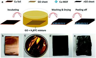
:![[thin space (1/6-em)]](https://www.rsc.org/images/entities/char_2009.gif) 1). In order to embed Cu-MOF NPs there between the rGO nanosheets, H3BTC was added into the GO dispersion as the organic ligand and stirred for 10 min. After that, a piece of well cleaned Cu foil (Fig. 1b) was immersed in the mixed solution. After incubation for 12 h (Fig. 1c), a black thin film was uniformly formed on the Cu foil accompanied by some aquamarine Cu-MOF particles suspended in the darkening solution, suggesting the synchronous reduction of GO and coordination of Cu-MOF. Subsequently, the foil was taken out of the mixed solution and rinsed carefully with ethanol and DI water successively to remove unreacted physisorbed GO sheets and the organic ligand (Fig. 1d). Once the foil was fully dried in an oven at 60 °C, a free-standing Cu-MOF/rGO film (weight ratio of 1
1). In order to embed Cu-MOF NPs there between the rGO nanosheets, H3BTC was added into the GO dispersion as the organic ligand and stirred for 10 min. After that, a piece of well cleaned Cu foil (Fig. 1b) was immersed in the mixed solution. After incubation for 12 h (Fig. 1c), a black thin film was uniformly formed on the Cu foil accompanied by some aquamarine Cu-MOF particles suspended in the darkening solution, suggesting the synchronous reduction of GO and coordination of Cu-MOF. Subsequently, the foil was taken out of the mixed solution and rinsed carefully with ethanol and DI water successively to remove unreacted physisorbed GO sheets and the organic ligand (Fig. 1d). Once the foil was fully dried in an oven at 60 °C, a free-standing Cu-MOF/rGO film (weight ratio of 1![[thin space (1/6-em)]](https://www.rsc.org/images/entities/char_2009.gif) :
:![[thin space (1/6-em)]](https://www.rsc.org/images/entities/char_2009.gif) 2) was peeled off from the Cu substrate (Fig. 1e). For comparison, a bare rGO film was prepared using a similar method without adding H3BTC to the GO dispersion.
2) was peeled off from the Cu substrate (Fig. 1e). For comparison, a bare rGO film was prepared using a similar method without adding H3BTC to the GO dispersion.
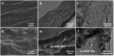
Scanning electron microscopy (SEM) and transmission electron microscopy (TEM) were used to characterize the microstructures of the Cu-MOF/rGO hybrid film and bare rGO film (Fig. 2). It can be observed that the bare rGO film has a relatively flat surface (Fig. 2a) and densely-packed layer structure (Fig. 2b) with a clear surface and good transparency of the GO nanosheets (Fig. 2c). In comparison, the hybrid film has a rougher surface with plenty of bumps (Fig. 2d) due to the embedded Cu-MOF particles there between the rGO layers (Fig. 2e), and the size of the Cu-MOF particles was mostly centered at around 50 nm. The loading of the Cu-MOF was confirmed by energy dispersive spectroscopy (EDS) shown in Fig. S1.† Further evidence can be found in the transmission electron microscopy (TEM) images shown in Fig. 2f that the Cu-MOF particles are successfully anchored on the surface of the rGO nanosheet.
It is found that the balance between the reduction of GO and the coordination of Cu2+ is crucial for the formation of the laminated hybrid films. Although both GO and H3BTC have the capability to transform Cu to free Cu2+ due to either corrosion or coordination,26 their ability can be readily tuned by adjusting the volume ratio between the DI water and DMF used in the mixed solution (Fig. S2†). As is schematically illustrated in Fig. 3a, when pure DMF is used as the solvent, Cu-MOF particles are self-nucleated and deposited on the surface of the Cu foil without obvious reduction of the GO nanosheets (Fig. S2a†). By contrast, in aqueous solution (Fig. 3b), since H3BTC has poor solubility, rGO thin film is preferentially formed on the Cu foil (Fig. S2f†) due to the potential difference between GO/rGO (φGO/rGO = 0.4 − 0.6 V) and Cu/Cu2+ (φo = 0.337 V) with ΔG < 0 (ΔG = −nFE = −nF[φGO/rGO − φM/Mn+], where ΔG, F, and E are the free energy change, Faraday constant, and cell potential, respectively). Therefore, the success of preparing the laminated Cu-MOF/rGO hybrid film is determined by the competitive relationship between the synchronous reduction of GO and the coordination of Cu2+ as schematically shown in Fig. 3c. The optimum volume ratio between water and DMF is determined to be VH2O/VDMF = 4![[thin space (1/6-em)]](https://www.rsc.org/images/entities/char_2009.gif) :
:![[thin space (1/6-em)]](https://www.rsc.org/images/entities/char_2009.gif) 1 when the speed of GO reduction and Cu-MOF formation reaches a balance (Fig. S2e†). Because GO and rGO nanosheets are both negatively charged due to the deprotonation of carboxyl groups,27 they have a strong tendency to capture the positively charged Cu2+ ions released from the Cu foil. These Cu2+ ions simultaneously coordinate with H3BTC to form Cu-MOF NPs. Since the generation of Cu2+ and the formation of Cu-MOF occurred in tandem with the conversion of GO to rGO, this smooth process guaranteed the assembly of a highly ordered stacking of rGO sheets with embedded Cu-MOF nanoparticles, leading to a well laminated structure.
1 when the speed of GO reduction and Cu-MOF formation reaches a balance (Fig. S2e†). Because GO and rGO nanosheets are both negatively charged due to the deprotonation of carboxyl groups,27 they have a strong tendency to capture the positively charged Cu2+ ions released from the Cu foil. These Cu2+ ions simultaneously coordinate with H3BTC to form Cu-MOF NPs. Since the generation of Cu2+ and the formation of Cu-MOF occurred in tandem with the conversion of GO to rGO, this smooth process guaranteed the assembly of a highly ordered stacking of rGO sheets with embedded Cu-MOF nanoparticles, leading to a well laminated structure.
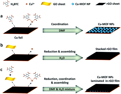 | ||
| Fig. 3 Schematic illustration of the growth mechanism of the Cu-MOF/rGO hybrid film. (a) DMF, (b) H2O and (c) DMF/H2O mixture served as the solvent, respectively. | ||
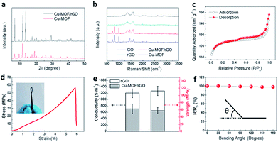
The X-ray diffraction (XRD) pattern of the hybrid film matches well with that of pure Cu-MOF particles (Fig. 4a), confirming the successful incorporation of Cu-MOF nanoparticles in the film.28 The reduction of GO to rGO and the existence of Cu-MOF in the hybrid film were also evidenced by Raman spectroscopy (Fig. 4b). The Raman peaks located at 1345 cm−1 and 1595 cm−1 are well-ascribed to the D band and G band of carbonaceous materials. Compared to GO, the rGO film grown on copper has an increased intensity ratio of the D band and G band (ID/IG), implying that parts of oxygen-containing groups on the GO nanosheets have been removed,29 and the successful reduction of GO by copper. On the other hand, except the peaks from the rGO nanosheets, the hybrid film shows a similar Raman spectrum to that of Cu-MOF, further suggesting the incorporation of Cu-MOF in the film. N2 adsorption and desorption isotherms and Barrett–Joyner–Halenda (BJH) pore size distribution analysis were performed and the results suggest the contribution of micro-pores from Cu-MOF and the meso- or macro-pores from rGO (Fig. 4c and S3†). The electrical conductivity and mechanical strength crucially determine the suitability and reliability of the hybrid film for supercapacitor applications. Owing to its unique architecture, the Cu-MOF/rGO hybrid film displays a tensile strength of 58 MPa with a failure strain of 6% (Fig. 4d) and a conductivity of 713 S cm−1 (Fig. 4e), which is slightly compromised compared to that of the bare rGO film (116 MPa and 1200 S cm−1) due to the incorporation of the Cu-MOF NPs. Besides, the hybrid film exhibits high flexibility and it can be rolled up, bent and even folded (inset in Fig. 4d) without an obvious change in the resistance (Fig. 4f).
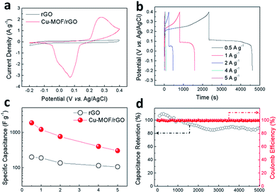
The electrochemical performance of the hybrid film electrode (Fig. S4†) was fully characterized using cyclic voltammetry (CV) and galvanostatic charge–discharge (GCD) techniques in 1 M KOH aqueous solution. The bare rGO film electrode tested as a reference exhibits a typical rectangular shaped CV curve (Fig. 5a) which does not show any distortion even at a high scan rate (Fig. S5†) indicating the good conductivity of the rGO film. In comparison, the Cu-MOF/rGO hybrid film electrode gives a much higher current density as the CV curve shown in Fig. 5a, which is attributed to redox reactions during the charge–discharge process. A pair of well-revolved peaks are observed, originating from the redox reaction of Cu(I)/Cu(II) coupled within Cu-MOF particles.30 With the increase of scan rate, the anodic peak shifts toward the positive potential and the cathodic peak shifts to the negative direction (Fig. S6†), demonstrating the quasi-reversible nature of the redox reactions. The GCD curves of the bare rGO film (Fig. S7†) and hybrid film (Fig. 5b) were tested at a current density ranging from 0.5 to 5 A g−1. Due to (1) the good conductivity restored during deposition31 and (2) the oxygen-containing functional groups on the surface of the rGO sheets,32 the bare rGO film delivers a specific capacitance of 200 F g−1 at 0.5 A g−1. Distinct from that of the bare rGO film with a typical triangle-shaped GCD curve, the hybrid Cu-MOF/rGO film electrode exhibits charge and discharge platforms at 0.3 and 0.1 V respectively (Fig. 5b), which correspond to the anodic and cathodic peaks in the CV curves. A high specific capacitance of 1871 F g−1 is obtained for the hybrid film at 0.5 A g−1 (Fig. 5c), which is over 9 times that of rGO (200 F g−1). Even though, due to the poor conductivity of Cu-MOF, the rate capability of the hybrid film is compromised within the scan rates of 0.5 to 5 A g−1 in comparison to the bare rGO film electrode (Fig. 5c), a capacitance of 300 F g−1 is still retained for the hybrid film electrode at 5 A g−1. This performance is much better than several reported MOF-based electrodes, such as the PANI-ZIF-67-CC flexible porous electrode (371 F g−1 at 10 mV s−1),20 the conductive two-dimensional Ni-HAB MOF electrode (427 F g−1 at 0.2 mV s−1),33 and the conductive Cu-CAT MOF nanowire array electrode (202 F g−1 at 0.5 A g−1).34 A comprehensive performance comparison is summarized in Table S1.† Such a high performance can be attributed to the following reasons: (1) the efficient reduction of the GO nanosheets provides the redox reactions with a highly conductive network, enhancing the electrochemical performance of the hybrid film; (2) Cu-MOF NPs having three-dimensional pores with open metal sites in the backbone structure offer redox centers that contribute to an improved capacitance;35 (3) the laminated nanostructure of the hybrid film not only effectively avoids the restacking of the rGO sheets but also ensures rapid electron transport throughout the network. Moreover, the electrode exhibits a capacitance retention of 89% after 5000 charge–discharge cycles with a nearly constant Coulomb efficiency of 100% (Fig. 5d). The slight decline in capacitance might be attributed to the partial conversion of Cu-MOFs to CuO during cycling, which is evidenced by XRD (Fig. S8†).
Conclusions
In summary, we demonstrate a solution-based single-step method to assemble a free-standing Cu-MOF/rGO hybrid film at ambient temperature. By simply tuning the solvent used, the synchronous reduction of GO and formation of Cu-MOF can be achieved to form a laminated hybrid film. The hybrid film features high mechanical strength, good electrical conductivity and excellent flexibility, and thus can be used as a flexible electrode directly without any binder or conductive agent. The Cu-MOF/rGO hybrid film delivers a high capacitance of 1871 F g−1 at 0.5 A g−1 and retained 89% of capacitance after 5000 cycles at 5 A g−1. The high flexibility and enhanced electrochemical performance mean our Cu-MOF/rGO hybrid film shows promise in applications in energy-storage devices that can be integrated with flexible and wearable electronics.Conflicts of interest
There are no conflicts to declare.Acknowledgements
This work was supported by the National Natural Science Foundation of China (11674140), the Natural Science Foundation of Jiangsu Province (BK20171018) and Jiangsu Specially-Appointed Professor program (54935012).Notes and references
- N. Choudhary, C. Li, J. Moore, N. Nagaiah, L. Zhai, Y. Jung and J. Thomas, Adv. Mater., 2017, 29, 1605336 CrossRef.
- P. Simon and Y. Gogotsi, Nat. Mater., 2008, 7, 845–854 CrossRef CAS.
- L. L. Zhang and X. S. Zhao, Chem. Soc. Rev., 2009, 38, 2520–2531 RSC.
- Y. Zhai, Y. Dou, D. Zhao, P. F. Fulvio, R. T. Mayes and S. Dai, Adv. Mater., 2011, 23, 4828–4850 CrossRef CAS.
- L. L. Zhang and X. S. Zhao, Chem. Soc. Rev., 2009, 38, 2520–2531 RSC.
- W. Gao, Y. Wan, Y. Dou and D. Zhao, Adv. Energy Mater., 2011, 1, 115–123 CrossRef CAS.
- T. Palaniselvam and J. B. Baek, 2D Mater., 2015, 2, 032002 CrossRef.
- V. Augustyn, P. Simon and B. Dunn, Energy Environ. Sci., 2014, 7, 1597–1614 RSC.
- H. Chen, J. Xu, X. Xu and Q. Zhang, Eur. J. Inorg. Chem., 2013, 2013, 1105–1108 CrossRef CAS.
- R. Chen, M. Knapp, M. Yavuz, S. Ren, R. Witte, R. Heinzmann, H. Hahn, H. Ehrenberg and S. Indris, Phys. Chem. Chem. Phys., 2015, 17, 1482–1488 RSC.
- J. Liu, J. Jiang, C. Cheng, H. Li, J. Zhang, H. Gong and H. J. Fan, Adv. Mater., 2011, 23, 2076–2081 CrossRef CAS.
- B. Zhao, L. Zhang, Q. Zhang, D. Chen, Y. Cheng, X. Deng, Y. Chen, R. Murphy, X. Xiong, B. Song, C. P. Wong, M.-S. Wang and M. Liu, Adv. Energy Mater., 2017, 8, 1702247 CrossRef.
- B. Zhao, D. Chen, X. Xiong, B. Song, R. Hu, Q. Zhang, B. H. Rainwater, G. H. Waller, D. Zhen, Y. Ding, Y. Chen, C. Qu, D. Dang, C. P. Wong and M. Liu, Energy Storage Materials, 2017, 7, 32–39 CrossRef.
- J. Park, M. Lee, D. Feng, Z. Huang, A. C. Hinckley, A. Yakovenko, X. Zou, Y. Cui and Z. Bao, J. Am. Chem. Soc., 2018, 140, 10315–10323 CrossRef CAS.
- M. S. Rahmanifar, H. Hesari, A. Noori, M. Y. Masoomi, A. Morsali and M. F. Mousavi, Electrochim. Acta, 2018, 275, 76–86 CrossRef CAS.
- C. Qu, Y. Jiao, B. Zhao, D. Chen, R. Zou, K. S. Walton and M. Liu, Nano Energy, 2016, 26, 66–73 CrossRef CAS.
- M. D. Allendorf, A. Schwartzberg, V. Stavila and A. A. Talin, Chem.–Eur. J., 2011, 17, 11372–11388 CrossRef CAS.
- M. Jahan, Q. Bao, J. X. Yang and K. P. Loh, J. Am. Chem. Soc., 2010, 132, 14487–14495 CrossRef CAS.
- C. Petit and T. J. Bandosz, Adv. Mater., 2010, 21, 4753–4757 CrossRef.
- L. Wang, X. Feng, L. Ren, Q. Piao, J. Zhong, Y. Wang, H. Li, Y. Chen and B. Wang, J. Am. Chem. Soc., 2015, 137, 4920–4923 CrossRef CAS.
- S. H. Kazemi, B. Hosseinzadeh, H. Kazemi, M. A. Kiani and S. Hajati, ACS Appl. Mater. Interfaces, 2018, 10, 23063–23073 CrossRef CAS.
- L. Hua, P. Shi, L. Li, C. Yu, R. Chen, Y. Gong, Z. Du, J. Y. Zhou, H. Zhang, X. Tang, G. Sun and W. Huang, ACS Appl. Mater. Interfaces, 2017, 9, 37022–37030 CrossRef CAS PubMed.
- G. Sun, J. An, C. K. Chua, H. Pang, J. Zhang and P. Chen, Electrochem. Commun., 2015, 51, 33–36 CrossRef CAS.
- G. Sun, X. Zhang, R. Lin, J. Yang, H. Zhang and P. Chen, Angew. Chem., Int. Ed., 2015, 127, 4734–4739 CrossRef.
- G. Sun, L. Zheng, Z. Zhan, J. Zhou, X. Liu and L. Li, Carbon, 2014, 68, 748–754 CrossRef CAS.
- G. Cai, W. Zhang, L. Jiao, S. H. Yu and H. L. Jiang, Chem, 2017, 2, 791–802 CAS.
- D. Li, M. B. Müller, S. Gilje, R. B. Kaner and G. G. Wallace, Nat. Nanotechnol., 2008, 3, 101–105 CrossRef CAS.
- Y. Li, J. Miao, X. Sun, J. Xiao, Y. Li, H. Wang, Q. Xia and Z. Li, Chem. Eng. J., 2016, 298, 191–197 CrossRef CAS.
- S. Stankovich, D. A. Dikin, R. D. Piner, K. A. Kohlhaas, A. Kleinhammes, Y. Jia, Y. Wu, S. B. T. Nguyen and R. S. Ruoff, Carbon, 2007, 45, 1558–1565 CrossRef CAS.
- G. Wang, J. Huang, S. Chen, Y. Gao and D. Cao, J. Power Sources, 2011, 196, 5756–5760 CrossRef CAS.
- Y. Shao, M. F. El-Kady, C. W. Lin, G. Zhu, K. L. Marsh, J. Y. Hwang, Q. Zhang, Y. Li, H. Wang and R. B. Kaner, Adv. Mater., 2016, 28, 6719–6726 CrossRef CAS.
- Z. D. Huang, B. Zhang, S. W. Oh, Q. B. Zheng, X. Y. Lin, N. Yousefi and J. K. Kim, J. Mater. Chem., 2012, 22, 3591–3599 RSC.
- D. Feng, T. Lei, M. R. Lukatskaya, J. Park, Z. Huang, M. Lee, L. Shaw, S. Chen, A. A. Yakovenko and A. Kulkarni, Nat. Energy, 2018, 3, 30–36 CrossRef CAS.
- W. H. Li, K. Ding, H. R. Tian, M. S. Yao, B. Nath, W. H. Deng, Y. Wang and G. Xu, Adv. Funct. Mater., 2017, 27, 1702067 CrossRef.
- K. M. Choi, H. M. Jeong, J. H. Park, Y. B. Zhang, J. K. Kang and O. M. Yaghi, ACS Nano, 2014, 8, 7451–7457 CrossRef CAS.
Footnotes |
| † Electronic supplementary information (ESI) available. See DOI: 10.1039/c8ta09065c |
| ‡ These authors contributed equally to this work. |
| This journal is © The Royal Society of Chemistry 2019 |

