Enabling highly efficient photocatalytic hydrogen generation and organics degradation via a perovskite solar cell-assisted semiconducting nanocomposite photoanode†
Xueqin
Liu‡
 ab,
Yang
Wang‡
a,
Xun
Cui
bc,
Meng
Zhang
b,
Bing
Wang
b,
Matthew
Rager
b,
Zhu
Shu
a,
Yingkui
Yang
 *c,
Zhen
Li
*a and
Zhiqun
Lin
 *b
*b
aEngineering Research Center of Nano-Geomaterials of Ministry of Education, Faculty of Materials Science and Chemistry, China University of Geosciences, Wuhan 430074, China. E-mail: liuxq@cug.edu.cn; zhenli@cug.edu.cn
bSchool of Materials Science and Engineering, Georgia Institute of Technology, Atlanta, GA 30332, USA. E-mail: zhiqun.lin@mse.gatech.edu
cKey Laboratory of Catalysis and Materials Science of State Ethnic Affairs Commission & Ministry of Education, School of Chemistry and Materials Science, South-Central University for Nationalities, Wuhan, 430074, China. E-mail: ykyang@mail.scuec.edu.cn
First published on 6th November 2018
Abstract
Organometal trihalide perovskite solar cells (PSCs) have been widely recognized as a promising photovoltaic device due to their impressive set of outstanding excellent optoelectronic properties. However, the instability and intermittent energy output caused by the intensity fluctuation and/or the daily cycle of sunlight have motivated the direct application of PSCs in other energy fields. Here, we report an integrated solar-energy-conversion/water-splitting device comprising a single-junction PSC and CdS-decorated TiO2 nanorod array (i.e., semiconducting CdS/TiO2 NRA nanocomposite) photoanode with excellent photoelectrochemical (PEC) performance. Intriguingly, the introduction of PSC is found to effectively suppress the recombination of electrons and holes during the PEC catalytic process. As a result, the integrated device yields an overall solar-to-hydrogen efficiency of 1.54% and exhibits a six-fold increase in the degradation rate of methylene blue over that of the CdS/TiO2 NRAs alone. As such, the crafting of a perovskite solar cell-assisted nanocomposite semiconductor photoanode may represent a viable route to alleviating the electron–hole recombination in water splitting and the degradation of organic pollutants, thus rendering the effective implementation of PSCs.
1. Introduction
Developing efficient and low-cost processes to convert solar energy to chemical energy and electricity is of key importance in facilitating environmental remediation and green energy generation.1 It is notable that as solar radiation is intermittent, the electricity converted via the use of solar cells needs to be used immediately or stored in various forms.2,3 Overcoming this problem requires judiciously integrating solar cells with other forms of energy conversion and storage systems, such as hydrogen generation,4,5 lithium-ion battery,6,7 supercapacitor,8,9 and fuel cells.10Recently, perovskite solar cells (PSCs) have emerged as a new class of revolutionary optoelectronic device due to their high efficiency, facile processing and low cost. Notably, the efficiency of PSCs has leaped from 3.8% to more than 23% over the past decade.11–14 While the stability and hysteresis of PSCs are currently the focus of fundamental research, much effort has also been devoted to the application of PSCs.15,16 For example, tandem PSCs have been integrated with NiFe layered double-hydroxide catalyst electrodes for sunlight-driven water splitting, yielding a solar-to-hydrogen efficiency of 12.3%.17 It is also interesting to note that four single PSCs have recently been connected in series and directly used for photocharging the lithium-ion battery.6 This integrated device can work continuously regardless of the availability of sunlight, showing a photoelectric conversion and storage efficiency of 7.80% with good cycling stability. Similarly, a striking 6.50% solar-to-CO efficiency has been achieved using series-connected PSCs, which provide a high open-circuit voltage.18
Photocatalysis is a promising solution for the efficient conversion and storage of solar energy, such as in hydrogen generation, CO2 reduction, and degradation of organic pollutants.19–21 However, the efficiency of photocatalysts is often plagued by the high charge recombination rates.22 In this regard, the introduction of PSCs may provide a bias potential to accelerate the transport of electrons, resulting in improved photocatalytic efficiency. For example, single-junction PSC has been connected with a BiVO4 photoanode in series for water splitting.23 This unique photoanode–photovoltaic configuration delivers a high solar-to-hydrogen efficiency of 2.5% in neutral solution. Similar work has been reported using a Fe2O3 nanorod array as photoanode,24 achieving a conversion efficiency of 2.4% when combined with the PSCs. In addition, photocatalytic degradation has proved to be an efficient approach for eliminating organic pollutants. To the best of our knowledge, solar-powered organic degradation based on PSCs has not yet been reported.
Herein, we report the crafting of an integrated device composed of a single-junction PSC and a CdS-decorated-TiO2-nanorod-array photoanode to enable solar-powered photocatalysis. CdS is a semiconductor with a narrow band gap of 2.42 eV, and it can be excited by visible light. More importantly, compared to Fe2O3 or BiVO4, the conduction band (CB) position of CdS is more negative than H2O/H2, thus favoring H2 generation. The CdS-decorated TiO2 nanorod arrays (denoted CdS/TiO2 NRAs) are grown on FTO glass, which is directly exploited as the semiconducting nanocomposite photoanode, thus dispensing with the need for spin-coating or doctor-blade processes. Interestingly, CdS/TiO2 NRAs are also a promising photocatalytic nanocomposite for degrading organics. We demonstrate, for the first time, the combination of the PSC with photocatalytic degradation. The introduction of PSC into water-splitting and organics degradation processes leads to an overall solar-to-hydrogen efficiency of 1.54% and a six-fold increase in the degradation rate over those of CdS/TiO2 NRAs alone.
2. Experimental
Synthesis of CdS/TiO2 nanorod composite arrays
Vertically oriented TiO2 NRAs on fluorine-doped tin oxide (FTO) glass (sheet resistance 15–18 Ω cm−2) were fabricated by the hydrothermal method according to previous work.25–27 CdS sensitizer was deposited on the TiO2 NRAs by a sequential chemical bath deposition (SCBD). Briefly, the TiO2 NRAs were dipped into a 0.05 M Cd(NO3)2 solution for 3 min, followed by washing with DI H2O. Then, as-prepared film was further immersed in 0.05 M Na2S for another 3 min and rinsed again with DI water. The above procedure was repeated 10 times to form CdS-decorated TiO2 NRAs (referred to as CdS/TiO2 NRAs). The XRD and SEM images of CdS/TiO2 NRAs are shown in Fig. S2 and S3,† respectively.Fabrication of perovskite solar cells
For the fabrication of mesoporous-structured PSCs, fluorine-doped tin oxide (FTO) was etched by reacting Zn powder with 2 M HCl solution and sequentially ultrasonicating in detergent, DI H2O, acetone and ethanol, followed by oxygen plasma treatment for 10 min. A compact TiO2 layer with thickness of 80–100 nm was deposited on the cleaned FTO glass by spin coating a commercial titanium diisopropoxide bis(acetylacetonate) solution (i.e., TiO2 precursors; 75 wt% in isopropanol, Sigma-Aldrich) diluted in ethanol, followed by heating at 125 °C for 5 min. After cooling to room temperature, commercial Dyesol 18NRT titania nanoparticle paste (diluted in methanol at 1![[thin space (1/6-em)]](https://www.rsc.org/images/entities/char_2009.gif) :
:![[thin space (1/6-em)]](https://www.rsc.org/images/entities/char_2009.gif) 4 mass ratio) was spin-coated on the compact TiO2 film described above at 3000 rpm for 30 s to form a mesoporous layer. After being annealed at 500 °C for 1 h, the TiO2 film was immersed in 0.05 M TiCl4 aqueous (>99%, Aldrich) at 70 °C for 30 min. The treated substrate was then rinsed with DI H2O and ethanol, followed by annealing at 500 °C for 1 h. Perovskite absorber layer was deposited by a two-step method.28 Briefly, PbI2 solution in DMF (500 mg mL−1), preheated at 70 °C, was spin-coated at 5000 rpm for 20 s, followed by immersion in CH3NH3I solution (10 mg mL−1 in isopropanol) for 20 s, then rinsed with isopropanol and dried 100 °C for 10 min. After the formation of perovskite layer, the commonly used hole transport layer spiro-MeOTAD was deposited by spin coating at 4000 rpm for 30 s. The spiro-MeOTAD solution was prepared by dissolving 72.3 mg spiro-MeOTAD, 28.8 μL 4-tert-butylpyridine and 17.5 μL of lithium bis(trifluoromethanesulfonyl) imide (Li-TFSI) solution (520 mg LI-TSFI in 1 mL acetonitrile, Sigma-Aldrich, 99.8%) in 1 mL anhydrous chlorobenzene. Finally, a 100 nm thick Ag layer was thermally evaporated on top of the device under a vacuum of 2 × 10⁻⁶ mbar to form the back contact. The cross-sectional view of the PSC is shown in Fig. S4.†
4 mass ratio) was spin-coated on the compact TiO2 film described above at 3000 rpm for 30 s to form a mesoporous layer. After being annealed at 500 °C for 1 h, the TiO2 film was immersed in 0.05 M TiCl4 aqueous (>99%, Aldrich) at 70 °C for 30 min. The treated substrate was then rinsed with DI H2O and ethanol, followed by annealing at 500 °C for 1 h. Perovskite absorber layer was deposited by a two-step method.28 Briefly, PbI2 solution in DMF (500 mg mL−1), preheated at 70 °C, was spin-coated at 5000 rpm for 20 s, followed by immersion in CH3NH3I solution (10 mg mL−1 in isopropanol) for 20 s, then rinsed with isopropanol and dried 100 °C for 10 min. After the formation of perovskite layer, the commonly used hole transport layer spiro-MeOTAD was deposited by spin coating at 4000 rpm for 30 s. The spiro-MeOTAD solution was prepared by dissolving 72.3 mg spiro-MeOTAD, 28.8 μL 4-tert-butylpyridine and 17.5 μL of lithium bis(trifluoromethanesulfonyl) imide (Li-TFSI) solution (520 mg LI-TSFI in 1 mL acetonitrile, Sigma-Aldrich, 99.8%) in 1 mL anhydrous chlorobenzene. Finally, a 100 nm thick Ag layer was thermally evaporated on top of the device under a vacuum of 2 × 10⁻⁶ mbar to form the back contact. The cross-sectional view of the PSC is shown in Fig. S4.†
Characterization and measurement
The UV-vis absorption spectrum measurements were performed by applying a Shimadzu UV-2600 spectrophotometer. The crystalline phase was characterized by X-ray diffraction (XRD, X'Pert-PRO, Panalytical, Holland) with Cu Kα radiation (λ = 0.154 nm). The XPS spectrum was collected on the ESCALAB MKII X-ray photoelectron spectrometer (K-Alpha 1063). A Keithley 2400 multisource meter was used to measure the current density–voltage (J–V) curves. The amount of CdS decorated on TiO2 RNAs was determined by an inductively coupled plasma-optical emission spectrometer (ICP-OES, Perkin Elmer, Optima 5300DV). Ultraviolet photoelectron spectroscopy (UPS) was conducted with a monochromatic He–I light source (21.22 eV) and a VG Scienta R4000 analyzer. A bias of −5 V was applied to observe the secondary electron cut-off edge. The PEC performance of CdS/TiO2 NRAs was measured on an electrochemical workstation (CHI 650E) using a three-electrode system in 1 M NaOH solution (pH = 13.8). The as-prepared CdS/TiO2 NRAs were used as the working electrode, a Pt wire as the counter electrode, and the Ag/AgCl electrode as the reference electrode. A 150 W xenon lamp coupled with an AM 1.5G filter (Newport) was used as the simulated sunlight source (100 mW cm−2).The PEC characterization of the integrated device composed of a single-junction PSC and a CdS/TiO2 NRA photoanode was performed in a quartz glass reactor using a two-electrode configuration in 0.1 M NaOH solution (pH = 13.8), as shown in Fig. S1,† where the CdS/TiO2 NRA photoanode served as the working electrode with an active area of 1 cm−2 and platinum foil was used as the counter electrode. The CdS/TiO2 NRA photoanode was attached to the reactor firmly by a metal clamp. A PSC was fixed directly behind the CdS/TiO2 NRA photoanode using a metal clamp. The CdS/TiO2 NRA photoanode was electrically connected to the counter electrode of the PSC via copper wire, while the Pt foil counter electrode was connected to the PSC working electrode via a potentiostat. The current versus time curve (J–t) was measured with zero external bias under simulated AM 1.5G solar illumination (a radiation intensity of 100 mW cm−2), using a Keithley 2400 multimeter as an ammeter. Prior to irradiation, the system was bubbled with nitrogen for 30 min to remove the dissolved O2. The amount of H2 evolved was collected and analyzed by gas chromatography (Varian 490 Micro-GC).
The PEC degradation system was nearly identical to the above H2 generation configuration described above, with 0.1 M Na2SO4 as the electrolyte. Methylene blue (MB) aqueous solution (10 mg L−1) was chosen as the target pollutant. The change of MB concentration was monitored by UV-vis spectrophotometer (Shimadzu UV-2600) every 10 min at a wavelength of 665 nm.
3. Results and discussion
Fig. 1 depicts the schematic of the integrated device in which PSC is connected externally to the CdS/TiO2 NRA photoanode. To verify the successful deposition of CdS on the surface of TiO2 NRAs, XPS analysis was conducted on the CdS/TiO2 NRA photoanode (Fig. S5†). The general survey spectrum confirms the existence of Cd, S, Ti, O and C elements. Compositional analysis of these peaks shows that the photoanode contains 3.27 at% Cd and 3.13 at% S, close to the stoichiometric value of CdS. This result is consistent with the ICP analyses (4.8 at%) shown in Fig. S6.† Under illumination, the charge carriers (i.e., electrons and holes) generated from the photoanode participate in the photocatalytic reactions (i.e., H2 generation or organic dye degradation as in this study). In a typical photocatalytic process, recombination of photoexcited carriers is often unavoidable, thereby limiting the photocatalytic efficiency and hindering the effective practical application of the photocatalytic process. In contrast, the integrated device in the present study renders an enhanced separation of electrons and holes due to the incorporation of a PSC. Under the irradiation of solar light, the open-circuit voltage (Voc) produced from the PSC is directly applied on the CdS/TiO2 NRA photoanode and Pt electrode, inducing the transport of photogenerated electrons through the external circuit, and thus efficiently accelerating the separation of electrons and holes. Such an integrated device enables the unassisted photoelectrocatalytic process without the need for external bias, demonstrating the attractive movable characteristic of such device.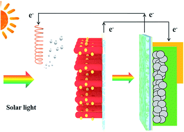 | ||
| Fig. 1 Schematic diagram depicting the combination of a PSC with a photocatalytic process. Left panel: Pt electrode. Right panel: CdS/TiO2 NRA photoanode and PSC. | ||
The current density–voltage (J–V) characteristic of the PSC used in this integrated device is presented in Fig. 2a. The cell has an open-circuit voltage of 1.05 V, short-circuit photocurrent density of 21.03 mA cm−2, and fill factor of 0.67, and thus an overall solar-to-electric power conversion efficiency (PCE) of 14.77%. A highly efficient PSC that can provide the needed potential is one of the key requirements for efficient photocatalysis. Another important prerequisite is having a photocatalyst with a suitable bandgap and position of the CB to ensure ample sunlight absorption and water splitting. In our study, CdS/TiO2 NRAs were employed as photocatalysts in the integrated device. Unlike the pure TiO2 NRAs, the absorption spectra of CdS/TiO2 NRAs extend into the visible region due to the incorporation of CdS nanoparticles, with an absorption edge at approximately 520 nm, as can be seen in the UV-visible diffuse reflectance spectra (Fig. S7†). Importantly, an obvious light transmittance at wavelengths greater than 500 nm is achieved by the photoanode, as shown in Fig. 2b, clearly reflecting that the photon energies can reach the PSC. It is noteworthy that the photocatalyst with both efficient visible light absorption and high transmittance, integrated with the PSC, renders a dual-absorber photocatalytic process, thereby utilizing the solar photons more efficiently.
During the photocatalytic process, the fast recombination rate of photogenerated electrons and holes represents a major drawback in the photocatalytic process. In our integrated device, CdS acts as the photon absorber layer, which can be excited under illumination due to its narrow bandgap. The energy levels of TiO2, CdS and Pt/FTO can be obtained by combining UV-vis diffuse reflectance spectra and UPS analyses, as shown in Fig. S8 and S9,† respectively. As the CB of TiO2 is less negative than that of CdS, the photoexcited electrons are subsequently injected into the CB of TiO2, then transfer to the FTO substrate, as illustrated in Fig. 3. Some of the electrons are depleted due to the nonradiative recombination with the trap states and holes in the VB of CdS.29 This issue can be mitigated by capitalizing on a PSC. Under illumination, the potential generated by the PSC can effectively drive the electrons to move from the FTO to the Pt counter electrode through the external circuit. As the applied potential enabled by the PSC accelerates the migration of charge carriers in the integrated device, the respective lifetimes of electrons and holes are increased. Consequently, the photocatalytic H2 generation and organics degradation are markedly enhanced, as discussed below.
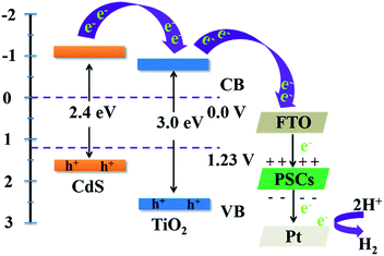 | ||
| Fig. 3 Schematic illustration of the charge transfer mechanism in the integrated device under solar light irradiation, where the incorporation of a PSC is shown on the right panel. | ||
The photocatalytic H2 evolution in the integrated device is investigated under visible light irradiation in an aqueous solution containing a mixture of 0.25 M Na2S and 0.35 M Na2SO3 as sacrificial reagents. The amount of evolved H2 on the CdS/TiO2 NRA nanocomposite photoanode with and without incorporating a PSC as a function of the irradiation time is shown in Fig. 4. The CdS/TiO2 NRA photoanode alone generated only ∼15 μmol of H2 after 2 h irradiation. Such low activity is due to the low quantum yield of TiO2. Upon the introduction of PSC into the photocatalytic process, the amount of H2 produced was largely increased. It is important to note that a greater than four times higher yield of H2 was observed in the presence of a PSC during the 2 h illumination. This is not surprising, as the fast transfer of photogenerated electrons induced by the introduction of PSC effectively suppressed the charge recombination process, thereby increasing the rate of hydrogen production on the Pt electrode.
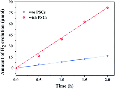 | ||
| Fig. 4 Photocatalytic hydrogen generation using the CdS/TiO2 NRA photoanode with (red circles) and without (blue stars) the incorporation of PSC. | ||
The solar to hydrogen (STH) conversion efficiency can be calculated according to the following equation:
 | (1) |
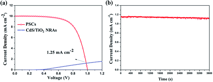
As the single PSC and CdS/TiO2 NRA photoanode are connected in series, their current is matched. Thus, the Jop can be identified from the intersection of the J–V curves of these two constituent devices.31 As shown in Fig. 5a, when the PSC is placed behind the CdS/TiO2 NRA photoanode, the PCE drops to 6.62% with a Jsc of 10.02 mA cm−2 and a Voc of 1.01 V. The predicted operating point for the integrated device is 1.25 mA cm−2, leading to a STH conversion efficiency of 1.54% according to eqn (1). It is worth noting that in the actual integrated device, a stable photocurrent density of 1.15 mA cm−2 was found (Fig. 5b) without degradation after 1 h of testing. The fluctuation and slight decrease of the current can be attributed to the bubble formation on the surfaces of the Pt counter electrode (H2) as well as the losses due to the connection of two individual constituent devices.24,32 Under a high operating current density, significant H2 evolution from the Pt electrode in the integrated device was thus observed under light irradiation.
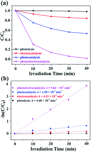
The photoelectrocatalysis (PEC, using PSC as potentiostat), photocatalysis (PC, without PSC), electrocatalysis (EC) and direct photolysis (DP) of methyl blue (MB) in aqueous solutions were performed over the CdS/TiO2 NRAs under solar light illumination (Fig. 6a). The CdS/TiO2 NRAs showed a negligible PC activity, with which only less than 50% of MB was degraded. In contrast, nearly 100% of MB was removed after the introduction of PSCs into the PC process (i.e., a PEC process) in 40 min, and the corresponding colour change for the MB solution is shown in Fig. S10.† Similar to the H2 generation process, the primary role of the PSC in photocatalytic degradation processes is to provide a bias voltage, which effectively suppresses the recombination of photogenerated electron–hole pairs. Consequently, abundant holes residing on the VB of CdS are responsible for the oxidation of MB. In order to quantitatively measure the degradation process, the kinetics of the degradation was studied using the pseudo-first order kinetics equation −ln![[thin space (1/6-em)]](https://www.rsc.org/images/entities/char_2009.gif) C/C0 = kt, where C and C0 are the reaction and initial concentrations of MB, respectively, t is the reaction time, and k is the apparent reaction rate constant. The MB degradation rate constant k for the PEC process was found to be 9.66 × 10⁻² min−1, which is six times over that of the PC process (1.58 × 10⁻² min−1), indicating a significant improvement of degradation rate after the introduction of a PSC (Fig. 6b). Notably, the integrated device of the single-junction PSC and CdS/TiO2 NRAs photoanode exhibits a competitive solar-to-hydrogen efficiency and degradation rate as compared to previous related works (Table S1†).
C/C0 = kt, where C and C0 are the reaction and initial concentrations of MB, respectively, t is the reaction time, and k is the apparent reaction rate constant. The MB degradation rate constant k for the PEC process was found to be 9.66 × 10⁻² min−1, which is six times over that of the PC process (1.58 × 10⁻² min−1), indicating a significant improvement of degradation rate after the introduction of a PSC (Fig. 6b). Notably, the integrated device of the single-junction PSC and CdS/TiO2 NRAs photoanode exhibits a competitive solar-to-hydrogen efficiency and degradation rate as compared to previous related works (Table S1†).
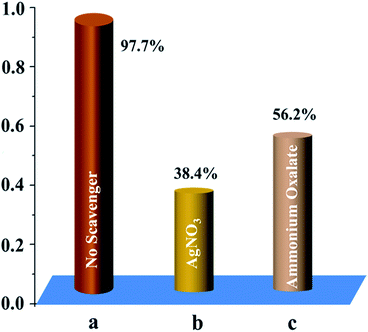
To underpin the importance of active species (i.e., electrons and holes) in the photocatalytic degradation process in the integrated device, control experiments with AgNO3 and ammonium oxalate added as radical scavengers for photogenerated electrons and holes, respectively, were conducted (Fig. 7). Clearly, the addition of AgNO3 inhibited the degradation of MB. When the radical hole scavenger ammonium oxalate was introduced into the PEC process, the photocatalytic reaction was also inhibited, however, to a lesser degree. On the basis of these observations, it is plausible that the electrons generated from PSC may also participate in the degradation reaction. Consequently, the electrons play a more important role than the holes toward MB degradation in the integrated device.
4. Conclusion
In summary, we demonstrated the effective integration of a single-junction PSC and a CdS/TiO2 NRAs photoanode for photocatalytic H2 generation and MB degradation. The markedly increased catalytic performance manifests the promising potential for the use of PSC in photocatalysis, thereby offering a means of alleviating the issues associated with instability and intermittent energy output of solar cells. The transfer and separation of photogenerated charges are greatly promoted due to the introduction of PSC. The integrated device delivered an unassisted STH efficiency of 1.54% and largely enhanced degradation rate of MB over the photocatalytic electrode alone. The latter, to the best of our knowledge, represents the first study on the application of PSC in photocatalytic degradation. We note that the performance of the integrated device is currently limited by the stability of PSC as well as the connection between PSC and photoanode. The stability improvement over moisture for PSC and the attempt for a wireless integration for the combined device may further enhance the device performance in H2 generation. Moreover, the replacement of Cd-containing semiconductor with environmentally benign elements would render the practical application of such integrated device. These studies are currently underway.Conflicts of interest
There are no conflicts to declare.Acknowledgements
The work was supported by the National Natural Science Foundation of China (41502030), the Natural Science Foundation of Hubei Province of China (2017CFB190), the Fundamental Research Funds for the Central Universities, China University of Geosciences (Wuhan) (CUG170638), and the Open Foundation of Engineering Research Center of Nano-Geomaterials of Ministry of Education (NGM2017KF002, NGM2018KF017).References
- L. Jin, B. Alotaibi, D. Benetti, S. Li, H. Zhao, Z. Mi, A. Vomiero and F. Rosei, Adv. Sci., 2016, 3, 1500345 CrossRef
.
- M. G. Walter, E. L. Warren, J. R. McKone, S. W. Boettcher, Q. Mi, E. A. Santori and N. S. Lewis, Chem. Rev., 2010, 110, 6446–6473 CrossRef CAS
.
- M. Yu, W. D. McCulloch, Z. Huang, B. B. Trang, J. Lu, K. Amine and Y. Wu, J. Mater. Chem. A, 2016, 4, 2766–2782 RSC
.
- Y. Wang, X. Liu, J. Liu, B. Han, X. Hu, F. Yang, Z. Xu, Y. Li, S. Jia, Z. Li and Y. Zhao, Angew. Chem., Int. Ed., 2018, 57, 5765–5771 CrossRef CAS
.
- Y. Wang, X. Liu, C. Zheng, Y. Li, S. Jia, Z. Li and Y. Zhao, Adv. Sci., 2018, 1700844 CrossRef
.
- J. Xu, Y. Chen and L. Dai, Nat. Commun., 2015, 6, 8103 CrossRef CAS
.
- W. Guo, X. Xue, S. Wang, C. Lin and Z. L. Wang, Nano Lett., 2012, 12, 2520–2523 CrossRef CAS
.
- X. Chen, H. Sun, Z. Yang, G. Guan, Z. Zhang, L. Qiu and H. Peng, J. Mater. Chem. A, 2014, 2, 1897–1902 RSC
.
- Y. Fu, H. Wu, S. Ye, X. Cai, X. Yu, S. Hou, H. Kafafy and D. Zou, Energy Environ. Sci., 2013, 6, 805 RSC
.
- J. I. San Martín, I. Zamora, J. J. San Martín, V. Aperribay and P. Eguia, Electr. Power Syst. Res., 2010, 80, 993–1005 CrossRef
.
- A. Kojima, K. Teshima, Y. Shirai and T. Miyasaka, J. Am. Chem. Soc., 2009, 131, 6050–6051 CrossRef CAS
.
- M. Saliba, T. Matsui, J.-Y. Seo, K. Domanski, J.-P. Correa-Baena, M. K. Nazeeruddin, S. M. Zakeeruddin, W. Tress, A. Abate and A. Hagfeldt, Energy Environ. Sci., 2016, 9, 1989–1997 RSC
.
- W. S. Yang, J. H. Noh, N. J. Jeon, Y. C. Kim, S. Ryu, J. Seo and S. I. Seok, Science, 2015, 348, 1234–1237 CrossRef CAS
.
- M. Saliba, S. Orlandi, T. Matsui, S. Aghazada, M. Cavazzini, J.-P. Correa-Baena, P. Gao, R. Scopelliti, E. Mosconi and K.-H. Dahmen, Nat. Energy, 2016, 1, 15017 CrossRef CAS
.
- Y. F. Xu, M. Z. Yang, B. X. Chen, X. D. Wang, H. Y. Chen, D. B. Kuang and C. Y. Su, J. Am. Chem. Soc., 2017, 139(16), 5660–5663 CrossRef CAS
.
- L. Zhou, Y. F. Xu, B. X. Chen, D. B. Kuang and C. Y. Su, Small, 2018, 14, 1703762 CrossRef
.
- J. Luo, J.-H. Im, M. T. Mayer, M. Schreier, M. K. Nazeeruddin, N.-G. Park, S. D. Tilley, H. J. Fan and M. Grätzel, Science, 2014, 345, 1593–1596 CrossRef CAS
.
- M. Schreier, L. Curvat, F. Giordano, L. Steier, A. Abate, S. M. Zakeeruddin, J. Luo, M. T. Mayer and M. Gratzel, Nat. Commun., 2015, 6, 7326 CrossRef CAS
.
- X. Liu, J. Yang, W. Zhao, Y. Wang, Z. Li and Z. Lin, Small, 2016, 12, 4077–4085 CrossRef CAS
.
- X. Liu, J. Iocozzia, Y. Wang, X. Cui, Y. Chen, S. Zhao, Z. Li and Z. Lin, Energy Environ. Sci., 2017, 10, 402–434 RSC
.
- Y. Tan, Z. Shu, J. Zhou, T. Li, W. Wang and Z. Zhao, Appl. Catal., B, 2018, 230, 260–268 CrossRef CAS
.
- T. Simon, N. Bouchonville, M. J. Berr, A. Vaneski, A. Adrović, D. Volbers, R. Wyrwich, M. Döblinger, A. S. Susha and A. L. Rogach, Nat. Mater., 2014, 13, 1013–1018 CrossRef CAS
.
- Y. S. Chen, J. S. Manser and P. V. Kamat, J. Am. Chem. Soc., 2015, 137, 974–981 CrossRef CAS
.
- Gurudayal, D. Sabba, M. H. Kumar, L. H. Wong, J. Barber, M. Grätzel and N. Mathews, Nano Lett., 2015, 15, 3833–3839 CrossRef CAS
.
- J. Cai, J. Ye, S. Chen, X. Zhao, D. Zhang, S. Chen, Y. Ma, S. Jin and L. Qi, Energy Environ. Sci., 2012, 5, 7575–7581 RSC
.
- H.-S. Kim, J.-W. Lee, N. Yantara, P. P. Boix, S. A. Kulkarni, S. Mhaisalkar, M. Grätzel and N.-G. Park, Nano Lett., 2013, 13, 2412–2417 CrossRef CAS
.
- C. K. Li, S. Y. H. Liou, C. L. Dong, P. H. Yeh and C. L. Chen, ACS Sustainable Chem. Eng., 2016, 4, 210–218 CrossRef
.
- J. Burschka, N. Pellet, S. J. Moon, R. Humphry-Baker, P. Gao, M. K. Nazeeruddin and M. Gratzel, Nature, 2013, 499, 316–319 CrossRef CAS
.
- S. Han, Y.-C. Pu, L. Zheng, J. Z. Zhang and X. Fang, J. Mater. Chem. A, 2015, 3, 22627–22635 RSC
.
- D. K. Zhong, S. Choi and D. R. Gamelin, J. Am. Chem. Soc., 2011, 133, 18370–18377 CrossRef CAS
.
- J. Luo, Z. Li, S. Nishiwaki, M. Schreier, M. T. Mayer, P. Cendula, Y. H. Lee, K. Fu, A. Cao, M. K. Nazeeruddin, Y. E. Romanyuk, S. Buecheler, S. D. Tilley, L. H. Wong, A. N. Tiwari and M. Grätzel, Adv. Energy Mater., 2015, 5, 1501520 CrossRef
.
- A. R. Bin, M. Yusoff and J. Jang, Chem. Commun., 2016, 52, 5824–5827 RSC
.
Footnotes |
| † Electronic supplementary information (ESI) available. See DOI: 10.1039/c8ta08998a |
| ‡ These authors contributed equally. |
| This journal is © The Royal Society of Chemistry 2019 |


