 Open Access Article
Creative Commons Attribution 3.0 Unported Licence
Fluorinated polysulfonamide based single ion conducting room temperature applicable gel-type polymer electrolytes for lithium ion batteries
K.
Borzutzki
a,
J.
Thienenkamp
b,
M.
Diehl
b,
M.
Winter
ab and
G.
Brunklaus
 *a
*a
aHelmholtz-Institute Münster, IEK-12, Forschungszentrum Jülich, Corrensstr. 46, 48149 Münster, Germany. E-mail: g.brunklaus@fz-juelich.de
bUniversity of Münster, MEET Battery Research Center, Institute of Physical Chemistry, Corrensstr. 46, 48149 Münster, Germany
First published on 4th December 2018
Abstract
Single ion conducting polymer electrolytes (SIPEs) comprised of homopolymers containing a polysulfonylamide segment in the polymer backbone are presented. The polymer structure contains –C(CF3)2 functional groups that due to better solubility allow for effective lithiation, yielding well-defined materials. An optimized polymer electrolyte membrane was fabricated as a 3![[thin space (1/6-em)]](https://www.rsc.org/images/entities/char_2009.gif) :
:![[thin space (1/6-em)]](https://www.rsc.org/images/entities/char_2009.gif) 1 blend of single ion conducting polymer and PVdF-HFP, which exhibits a high ionic conductivity of 0.52 mS cm−1 and an impressive lithium ion transference number of 0.9, as well as a 7Li self-diffusion coefficient of 4.6 × 10⁻¹¹ m2 s−1 at 20 °C. The presented polymer electrolyte has superior oxidative stability and long-term stability against lithium metal, thus facilitating operation in LiNi1/3Mn1/3CO1/3O2 (NMC111)/lithium metal cells at 20 °C and 60 °C, thereby clearly demonstrating the application potential of this class of materials.
1 blend of single ion conducting polymer and PVdF-HFP, which exhibits a high ionic conductivity of 0.52 mS cm−1 and an impressive lithium ion transference number of 0.9, as well as a 7Li self-diffusion coefficient of 4.6 × 10⁻¹¹ m2 s−1 at 20 °C. The presented polymer electrolyte has superior oxidative stability and long-term stability against lithium metal, thus facilitating operation in LiNi1/3Mn1/3CO1/3O2 (NMC111)/lithium metal cells at 20 °C and 60 °C, thereby clearly demonstrating the application potential of this class of materials.
1. Introduction
Lithium metal constitutes an attractive anode material for lithium ion batteries due to its high specific capacity and low electrochemical potential, thereby in principle facilitating batteries with high energy density.1,2 Currently, the application of lithium metal in batteries is restricted due to safety issues associated with dendrite growth and rather instable solid electrolyte interphase (SEI) formation.3–7 An approach to overcome this challenge comprises polymer electrolytes, which due to their beneficial mechanical properties can reduce dendrite growth.8–10 Single ion conducting polymers are a particularly promising class of materials, which in contrast to typically applied dual ion conducting liquid electrolytes11,12 afford high transference numbers and thus significantly reduced polarization effects, since merely lithium ions are mobile while the charge-balancing anions are covalently attached to the polymer backbone.13–15 Based on theoretical work, an immobilization of anions allows for reduced dendrite formation considering that the dendrite initiation time (so-called Sand's time) τ is reversely proportional to the anion transference number ta,16–18 which in the case of single ion conducting polymer electrolytes tends to converge to zero provided that the lithium ion transference number tLi+ approaches one.For a successful implementation of single lithium ion conducting polymer electrolytes, various concepts were proposed. Different anionic anchor groups carrying Li ions may be utilized, including carboxyl groups, sulfonate groups,15,19–22 bis(sulfonyl)imides15,23–27 and sp3 boron species.15,28–31 In the case of carboxyl and sulfonate groups, the Li ions strongly associate with the anions so that merely a low concentration of free Li ions is present.19,32 The B–O bond in boron based anions, however, is highly moisture sensitive; therefore long-term electrochemical stability appears questionable.14 In view of the rather favorable properties in terms of high ion dissociation degrees, bis(sulfonyl)imides are considered as versatile anionic moieties.
Single ion conducting polymer electrolytes may be “dry” or gel-type polymers that are plasticized with a salt-free organic solvent or an ionic liquid (IL). In “dry” polymer electrolytes, the anionic groups should be attached to polymer side chains to enable sufficient ionic transport, e.g. via inter-chain hopping, whereas for a gel-type polymer electrolyte anions either can be located at side chains or at the polymer backbone, since the ion transport is likely dominated by the present solvent or IL.33–35 The prominent advantages of gel-type polymer electrolytes comprise superior ionic conductivity and lower electrolyte–electrode interfacial resistances compared to rather “dry” materials, despite the fact that substantial progress was achieved for “dry” polymer electrolytes in recent years.8,13,36–39 Notably, sufficient polymer flexibility results either from incorporation of rather flexible, linear polymer compounds into single ion conducting polymer structures or from blending of aromatic single ion conducting polymers (that tend to be brittle when fabricated as a self-standing membrane) with another polymer having a linear structure.34 Previous reports indeed revealed the beneficial characteristics of single ion conducting gel-type polymer electrolytes derived from aromatic polysulfonamide-based homopolymers composed of polysulfonylamide anionic moieties in the polymer backbone.26,27,40–47 Due to its good mechanical properties demonstrated from application as a gel-type polymer electrolyte in lithium ion batteries,48,49 PVdF-HFP was proposed as a possible blend partner. The membranes were fabricated by a solution cast method, yielding porous structures that were further plasticized with a salt-free and thermally stable solvent solution such as EC![[thin space (1/6-em)]](https://www.rsc.org/images/entities/char_2009.gif) :
:![[thin space (1/6-em)]](https://www.rsc.org/images/entities/char_2009.gif) PC or EC
PC or EC![[thin space (1/6-em)]](https://www.rsc.org/images/entities/char_2009.gif) :
:![[thin space (1/6-em)]](https://www.rsc.org/images/entities/char_2009.gif) DEC, respectively. The resulting polymer electrolyte membranes afforded a high oxidative stability of at least 4.0 V as well as adequate ionic conductivity (10−4 to 10−3 S cm−1). To the best of our knowledge, in most reported work, the considered polymers were lithiated via treatment with lithium hydroxide. Based on significant signals at 3.33 pm in the corresponding 1H NMR spectra of the resulting materials in DMSO-(d6),26,27,40–47 an unintentional but substantial presence of either residual water or unreacted lithium hydroxide within the polymers has to be assumed, even though for long-term battery application, extraordinary high purity and anhydrous electrolytes are essential in order to avoid continuous material degradation, while facilitating high electrochemical performance of lithium metal cells.
DEC, respectively. The resulting polymer electrolyte membranes afforded a high oxidative stability of at least 4.0 V as well as adequate ionic conductivity (10−4 to 10−3 S cm−1). To the best of our knowledge, in most reported work, the considered polymers were lithiated via treatment with lithium hydroxide. Based on significant signals at 3.33 pm in the corresponding 1H NMR spectra of the resulting materials in DMSO-(d6),26,27,40–47 an unintentional but substantial presence of either residual water or unreacted lithium hydroxide within the polymers has to be assumed, even though for long-term battery application, extraordinary high purity and anhydrous electrolytes are essential in order to avoid continuous material degradation, while facilitating high electrochemical performance of lithium metal cells.
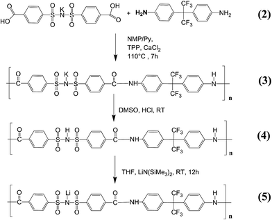
Herein, we introduce a homopolymer containing polysulfonylamide moieties at the polymer backbone, which was tailored by introducing a –C(CF3)2 functional group (Fig. 1). The obtained polymer exhibited enhanced solubility in aprotic polar solvents (such as THF), thereby allowing for the utilization of an improved lithiation method, affording fully defined lithiation and complete removal of residual solvent or unreacted species. A series of single ion conducting polymers (homopolymers) were prepared, where carboxyl(benzene sulphonyl)imide was combined with different dianiline units including p-phenylenediamine, benzidine, 4,4′-diaminodiphenylsulfone and 4,4′-(hexafluoroisopropylidene)dianiline, respectively. Nevertheless, merely the fluorinated species exhibited sufficient solvent solubility for processing, which is considered essential to reproducibly achieve full lithiation of the polymers. The derived single ion conducting polymer (5) was blent with PVdF-HFP and swollen in a solvent solution composed of EC![[thin space (1/6-em)]](https://www.rsc.org/images/entities/char_2009.gif) :
:![[thin space (1/6-em)]](https://www.rsc.org/images/entities/char_2009.gif) PC (1
PC (1![[thin space (1/6-em)]](https://www.rsc.org/images/entities/char_2009.gif) :
:![[thin space (1/6-em)]](https://www.rsc.org/images/entities/char_2009.gif) 1, v/v) for the fabrication of polymer electrolyte membranes. Upon variation of the single ion conducting polymer to PVdF-HFP ratio, an optimized blend membrane with sufficient mechanical stability and improved ionic conductivity was successfully produced.
1, v/v) for the fabrication of polymer electrolyte membranes. Upon variation of the single ion conducting polymer to PVdF-HFP ratio, an optimized blend membrane with sufficient mechanical stability and improved ionic conductivity was successfully produced.
 | ||
| Fig. 1 Schematic route of the polycondensation and ion exchange yielding the final lithiated single ion conducting polymer (5). | ||
2. Experimental section
2.1 Materials
p-Toluenesulfonamide (97%), p-toluenesulfonyl chloride (97%), potassium permanganate (KMnO4), lithium hydroxide monohydrate, calcium chloride, N-methyl-2-pyrrolidone (NMP, anhydrous, 99.8%), pyridine (anhydrous, 99.8%), tetrahydrofuran (THF, anhydrous, 99.8%), lithium bis(trismethylsilyl)amide solution (1 M in THF), and terephthalic acid (98%) were purchased from Sigma Aldrich, Germany. 4,4′-(Hexafluoroisopropylidene)dianiline (98%) was obtained from TCI Europe and poly(vinylidene difluoride-co-hexafluoropropylene) PVdF-HFP (Kynar FLEX LBG) was purchased from Arkema, Austria. Concentrated hydrochloric acid, methanol (AR), dimethylsulfoxide (DMSO, AR) and triphenylphosphite (TPP, AR) were acquired from VWR. Ethylene carbonate (EC) and propylene carbonate (PC) were purchased from BASF, Germany. LiNi1/3Co1/3Mn1/3O2 was obtained from Shanshan (China), carbon black (Super C65) was obtained from Imerys Graphite and carbon and polyvinylidene difluoride (PVdF, Solef 5130) from Solvay, Belgium. Calcium chloride was dried at 180 °C under vacuum for 48 hours, 4,4′-(hexafluoroisopropylidene)dianiline was dried at 100 °C under vacuum for 24 hours before use.2.2 Synthesis
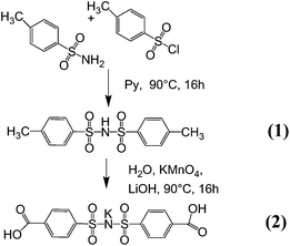
Synthesis of bis(4-methy benzene sulphonyl)imide (1). The synthesis of the bis(4-methy benzene sulphonyl)imide monomer (1) was achieved based on the Hinsberg reaction in previous work.26,27,42–45,50 Using aqueous media for the reaction of the highly reactive sulfonyl chloride, however, often results in significantly reduced reaction yields (about 40%) due to a high degree of side reactions. Therefore, the Einhorn reaction was performed in anhydrous pyridine. Equivalent molar ratios of p-toluenesulfon-amide (7.50 g, 43.80 mmol) and p-toluenesulfonyl chloride (8.45 g, 43.80 mmol) were dissolved in 10 ml of the solvent at 90 °C separately, and the p-toluenesulfonamide solution was stirred while the p-toluenesulfonyl chloride solution was added dropwise. The reaction mixture was stirred for 12 hours (Fig. 2). Afterwards, using a Schlenk line and an additional cooling trap the solvent was vaporized under reduced pressure at 100 °C, a condition where unreacted p-toluenesulfonamide sublimed. The obtained product was washed with 500 ml of distilled water, filtered and dried under vacuum at 100 °C for 48 hours. A white powder was obtained with a yield of 69% (9.88 g). The absence of the signal in the 1H NMR spectrum corresponding to residual solvent (pyridine or H2O) or the reagent of the product indicates high purity of the bis(4-methy benzene sulphonyl)imide. 1H NMR (DMSO-d6): 7.20 (d, 4H), 7.54 (d, 4H), and 2.33 (s, 6H); ESI−m/z: 325.04 (100%, (CH3–C6H4–SO2)2N−).
 | ||
| Fig. 2 Schematic route of the synthesis of the potassium(4-carboxyl benzene sulphonyl)imide monomer (2) under investigation of the Einhorn reaction (step 1) and end group functionalization (step 2). | ||
Synthesis of the potassium(4-carboxyl benzene sulphonyl)imide monomer (2). Functionalization of the methyl end groups of bis(4-methy benzene sulphonyl)imide (1) was performed dissolving 9.50 g (29.15 mmol) of bis(4-methy benzene sulphonyl)imide (1) and 1 equivalent (0.6258 g, 29.15 mmol) LiOH·H2O in 500 ml of deionized water at 95 °C (Fig. 2). Then, 60.80 g of KMnO4 (3 eq., 87.45 mmol) were slowly added to the solution and the reaction solution was stirred for 12 hours under reflux. The solution was cooled down to 50 °C and MnO2 was filtered off, yielding a clear filtrate. Precipitation of the raw product from the filtrate was achieved by acidification with concentrated HCl (until pH = 1). The white precipitate was filtered off and washed with 1000 ml methanol, and then dried under vacuum at 100 °C, yielding 8.00 g of product (65%) (2). 1H NMR (DMSO-d6): 7.73 (d, 4H), 7.90 (d, 42H), and 13.15 (s, 2H); ESI−m/z: 384.99 (100%, (COOH–C6H4–SO2)2N−).
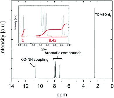
Lithiation of the polymer (4). The preparation of lithiated polymers based on the polysulfonamide monomer was often achieved upon application of lithium hydroxide (LiOH) in previous reports,26,27,40–47 despite the fact that the corresponding 1H NMR spectra of the polymers exhibited significant signals at 3.33 pm, clearly indicating the unintentional presence of either unreacted LiOH or residual water. Since the fluorinated single ion conducting polymer introduced in this work shows good solubility in THF compared to polysulfonamides containing other functional groups, successful lithiation was achieved with 1 M lithium bis(trimethylsilyl)amide. 1.1 g polymer (4) was dissolved in 300 ml anhydrous THF under an argon atmosphere and 1 eq. (1.61 ml) of the lithium base was added dropwise so that the lithiated product precipitated from the reaction solution. The reaction solution was allowed to stir overnight and the lithiated polymer (5) was collected after removing the solvent and bis(trimethylsilyl)amine under reduced pressure at 80 °C. The yield was 1.09 g (98%). Full lithiation was confirmed by inductively coupled plasma optical emission spectroscopy (ICP-OES). The corresponding 1H NMR spectrum of (5) (Fig. 3) showed four doublet signals at 7.35 ppm, 7.84 ppm, 7.91 ppm and 7.97 ppm attributed to aromatic compounds, and a singlet at 10.59 ppm related to CO–NH coupling of the monomers. The ratio of the integrated peak areas of the coupling proton to aromatic compounds was 1
![[thin space (1/6-em)]](https://www.rsc.org/images/entities/char_2009.gif) :
:![[thin space (1/6-em)]](https://www.rsc.org/images/entities/char_2009.gif) 8.4 (theoretically: 1
8.4 (theoretically: 1![[thin space (1/6-em)]](https://www.rsc.org/images/entities/char_2009.gif) :
:![[thin space (1/6-em)]](https://www.rsc.org/images/entities/char_2009.gif) 8). The absence of further signals confirmed the rather high purity and successful removal of solvents.
8). The absence of further signals confirmed the rather high purity and successful removal of solvents.
2.3 Preparation of the single ion conducting polymer electrolyte membrane
Four different membrane compositions were made, where the actual amount of lithiated polymer increased in order to obtain membranes with good ionic conductivity and sufficient mechanical flexibility. Weight ratios of 1![[thin space (1/6-em)]](https://www.rsc.org/images/entities/char_2009.gif) :
:![[thin space (1/6-em)]](https://www.rsc.org/images/entities/char_2009.gif) 1, 3
1, 3![[thin space (1/6-em)]](https://www.rsc.org/images/entities/char_2009.gif) :
:![[thin space (1/6-em)]](https://www.rsc.org/images/entities/char_2009.gif) 5, 2
5, 2![[thin space (1/6-em)]](https://www.rsc.org/images/entities/char_2009.gif) :
:![[thin space (1/6-em)]](https://www.rsc.org/images/entities/char_2009.gif) 6 and 1
6 and 1![[thin space (1/6-em)]](https://www.rsc.org/images/entities/char_2009.gif) :
:![[thin space (1/6-em)]](https://www.rsc.org/images/entities/char_2009.gif) 7, respectively, of PVdF-HFP to lithiated polymer were considered. For each membrane, a total amount of 400 mg of polymer (5) was dissolved in 4 ml NMP at 60 °C. The solution was cast in a Petri dish and placed into a vacuum oven at 80 °C overnight yielding a homogeneous polymer membrane of about 80 μm thickness. Disks of 12 or 13 mm diameter were cut from the membrane and further dried for 48 hours at 100 °C under vacuum prior to soaking them with EC
7, respectively, of PVdF-HFP to lithiated polymer were considered. For each membrane, a total amount of 400 mg of polymer (5) was dissolved in 4 ml NMP at 60 °C. The solution was cast in a Petri dish and placed into a vacuum oven at 80 °C overnight yielding a homogeneous polymer membrane of about 80 μm thickness. Disks of 12 or 13 mm diameter were cut from the membrane and further dried for 48 hours at 100 °C under vacuum prior to soaking them with EC![[thin space (1/6-em)]](https://www.rsc.org/images/entities/char_2009.gif) :
:![[thin space (1/6-em)]](https://www.rsc.org/images/entities/char_2009.gif) PC (1
PC (1![[thin space (1/6-em)]](https://www.rsc.org/images/entities/char_2009.gif) :
:![[thin space (1/6-em)]](https://www.rsc.org/images/entities/char_2009.gif) 1, v/v) solvent solution. EC
1, v/v) solvent solution. EC![[thin space (1/6-em)]](https://www.rsc.org/images/entities/char_2009.gif) :
:![[thin space (1/6-em)]](https://www.rsc.org/images/entities/char_2009.gif) PC (1
PC (1![[thin space (1/6-em)]](https://www.rsc.org/images/entities/char_2009.gif) :
:![[thin space (1/6-em)]](https://www.rsc.org/images/entities/char_2009.gif) 1, v/v) was selected due to its superior thermal stability compared to other solvent mixtures used for battery applications, containing a linear carbonate compound such as e.g. diethyl carbonate (DEC), dimethyl carbonate (DMC) or ethyl methyl carbonate (EMC).53 The weight of the membranes was measured after removing the residual liquid on the surface of the polymer film. The corresponding solvent uptake (SU) was derived from the following equation:
1, v/v) was selected due to its superior thermal stability compared to other solvent mixtures used for battery applications, containing a linear carbonate compound such as e.g. diethyl carbonate (DEC), dimethyl carbonate (DMC) or ethyl methyl carbonate (EMC).53 The weight of the membranes was measured after removing the residual liquid on the surface of the polymer film. The corresponding solvent uptake (SU) was derived from the following equation: | (1) |
2.4 Preparation of the cathode
For the preparation of LiNi1/3Co1/3Mn1/3O2 (NMC111) containing cathode material, 0.132 g (3 wt%) PVdF was dissolved in 6 ml NMP and stirred overnight. Subsequently, 0.132 g (3 wt%) of carbon black, 0.132 g (3 wt%) of lithiated terephthalic acid and 4 g (91 wt%) of NMC were added and the viscous solution was transferred to a swing mill MM 400 (Retsch Technology, Haan, Germany) stirring for 30 min at a frequency of 30 Hz. The slurry was then cast onto an aluminum current collector using a doctor blade technique at a gap width of 50 μm. The obtained coating was dried at 80 °C overnight, followed by further drying at 80 °C under vacuum. The electrodes were calendered using a roll press. The thickness of the two rolls was decreased from the initial thickness of the electrodes (current collector + coating (20 μm + 26 μm = 46 μm)) down to the thickness of the current collector + half of the initial coating thickness in two steps (to 20 μm + 13 μm = 33 μm), thereby reaching a compression of the coating of 50%. The final electrode coating thickness was 13 ± 1 μm and the mass loading was 2.8 mg cm−2.2.5 Methods
 | (2) |
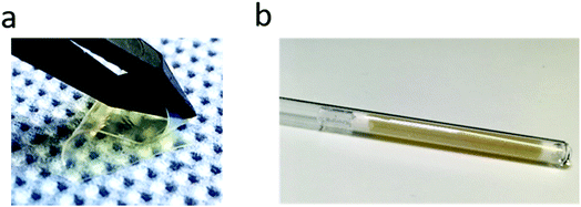 | ||
Fig. 4 (a) Picture of the swollen SIPE membrane (PVdF-HFP to lithiated polymer weight ratio 1![[thin space (1/6-em)]](https://www.rsc.org/images/entities/char_2009.gif) : :![[thin space (1/6-em)]](https://www.rsc.org/images/entities/char_2009.gif) 3) and (b) sample prepared for PFG-NMR measurements. 3) and (b) sample prepared for PFG-NMR measurements. | ||
ICP-OES measurements were performed using a Spectro ARCOS EOP device (Spectro Analytical Instruments GmbH, Kleve, Germany) after having the polymer dissolved using a microwave-assisted acid digestion (Anton Paar Multiwave Pro, Graz, Austria).
For total reflection X-ray fluorescence (TXRF) measurements, a Picofox S2 system equipped with Spectra 7.5 software (Bruker Corporation, Billerica, MA, USA) was used. The polymer sample was placed on a quartz glass carrier from Bruker Corporation.
Thermogravimetric analysis (TGA) was performed on a Q5000IR instrument (TA Instruments) applying a heating rate of 10 °C min−1 from room temperature to 700 °C under an oxygen gas atmosphere. Differential scanning calorimetry (DSC) was conducted between −150 °C and 150 °C with a heating rate of 10 °C min−1 on a Q2000 device (TA Instruments).
Scanning electron microscopy (SEM) was used to investigate the morphology (surface and cross section) of the polymer membranes. Cross sections were prepared by immersing the samples in liquid nitrogen and breaking the membranes. Multiple areas per sample were analyzed on an Auriga CrossBeam workstation from Zeiss (Germany) at an acceleration voltage of 3 kV.
The lithium-ion transference number (tLi+) was determined using the combined potentiostatic polarization and complex impedance measurement technique proposed by Evans et al.54 The membrane was sandwiched between two non-blocking lithium metal electrodes and the symmetrical cell was measured at 40 °C using an Autolab PGSTAT302N (Metrohm, Modul: FRA V2.0, Nova-Software 1.6). Impedance spectra were collected between 1 Hz and 2 GHz and a DC polarization voltage ΔV of 10 mV was applied across the sample. Subsequently, the lithium ion transference number was determined by
 | (3) |
The electrochemical stability of the polymer blend was determined using a VSP instrument (Bio-Logic Science Instruments). Measurements were conducted in a three electrode cell setup using lithium as the counter and reference electrode and platinum or copper as the working electrode for oxidative or reductive stability, respectively. A scan rate of 80 μV s−1 was applied in the potential range between −0.5 V and 6 V (vs. Li/Li+).
Cycling investigations were performed on a Maccor 4000 battery analysis system (USA) between 3.0 V and 4.3 V vs. Li/Li+ (constant current charging, CC), while the cells are at constant temperature in a climatic chamber, at either 60 °C or 20 °C, respectively.
3. Results and discussion
3.1 Polymer membrane composition and ionic transport
Upon varying the contents of both aromatic single ion conducting polymer and mechanically stable PVdF-HFP, an optimized composition for superior polymer membrane performance was identified. Weight ratios of lithiated polymer and PVdF-HFP of 1![[thin space (1/6-em)]](https://www.rsc.org/images/entities/char_2009.gif) :
:![[thin space (1/6-em)]](https://www.rsc.org/images/entities/char_2009.gif) 1,19,27,29 2
1,19,27,29 2![[thin space (1/6-em)]](https://www.rsc.org/images/entities/char_2009.gif) :
:![[thin space (1/6-em)]](https://www.rsc.org/images/entities/char_2009.gif) 3,28 3
3,28 3![[thin space (1/6-em)]](https://www.rsc.org/images/entities/char_2009.gif) :
:![[thin space (1/6-em)]](https://www.rsc.org/images/entities/char_2009.gif) 2 (ref. 41) and 2
2 (ref. 41) and 2![[thin space (1/6-em)]](https://www.rsc.org/images/entities/char_2009.gif) :
:![[thin space (1/6-em)]](https://www.rsc.org/images/entities/char_2009.gif) 1,27 respectively, were utilized for membrane fabrication in previous studies of similar non-fluorinated polysulfonamide containing homopolymers, though none of the studies included an optimization of the blend composition. In the case of binary blends comprised of fluorinated polysulfonamide carrying the conducting species (in this case Li) and flexible PVdF-HFP, it can be expected that a higher content of aromatic polymer yields improved ionic conductivity of the resulting polymer electrolyte membrane. Nevertheless, sufficient mechanical stability has to be maintained for the fabrication of membranes that are applicable in Li ion batteries, so that a minimum amount of PVdF-HFP (or any other film-forming blend partner) should be present. Notably, four different membranes with corresponding PVdF-HFP to lithiated polymer ratios of 1
1,27 respectively, were utilized for membrane fabrication in previous studies of similar non-fluorinated polysulfonamide containing homopolymers, though none of the studies included an optimization of the blend composition. In the case of binary blends comprised of fluorinated polysulfonamide carrying the conducting species (in this case Li) and flexible PVdF-HFP, it can be expected that a higher content of aromatic polymer yields improved ionic conductivity of the resulting polymer electrolyte membrane. Nevertheless, sufficient mechanical stability has to be maintained for the fabrication of membranes that are applicable in Li ion batteries, so that a minimum amount of PVdF-HFP (or any other film-forming blend partner) should be present. Notably, four different membranes with corresponding PVdF-HFP to lithiated polymer ratios of 1![[thin space (1/6-em)]](https://www.rsc.org/images/entities/char_2009.gif) :
:![[thin space (1/6-em)]](https://www.rsc.org/images/entities/char_2009.gif) 1, 3
1, 3![[thin space (1/6-em)]](https://www.rsc.org/images/entities/char_2009.gif) :
:![[thin space (1/6-em)]](https://www.rsc.org/images/entities/char_2009.gif) 5, 1
5, 1![[thin space (1/6-em)]](https://www.rsc.org/images/entities/char_2009.gif) :
:![[thin space (1/6-em)]](https://www.rsc.org/images/entities/char_2009.gif) 3 and 1
3 and 1![[thin space (1/6-em)]](https://www.rsc.org/images/entities/char_2009.gif) :
:![[thin space (1/6-em)]](https://www.rsc.org/images/entities/char_2009.gif) 7 (wt%
7 (wt%![[thin space (1/6-em)]](https://www.rsc.org/images/entities/char_2009.gif) :
:![[thin space (1/6-em)]](https://www.rsc.org/images/entities/char_2009.gif) wt%) were fabricated. The membrane containing 12.5 wt% of PVdF-HFP (sample 1
wt%) were fabricated. The membrane containing 12.5 wt% of PVdF-HFP (sample 1![[thin space (1/6-em)]](https://www.rsc.org/images/entities/char_2009.gif) :
:![[thin space (1/6-em)]](https://www.rsc.org/images/entities/char_2009.gif) 7) became chapped after drying under vacuum and removal of the glass substrate, but all other membrane compositions were found to be suitable as electrolyte membranes and were immersed in a solvent solution of EC
7) became chapped after drying under vacuum and removal of the glass substrate, but all other membrane compositions were found to be suitable as electrolyte membranes and were immersed in a solvent solution of EC![[thin space (1/6-em)]](https://www.rsc.org/images/entities/char_2009.gif) :
:![[thin space (1/6-em)]](https://www.rsc.org/images/entities/char_2009.gif) PC (v/v, 1
PC (v/v, 1![[thin space (1/6-em)]](https://www.rsc.org/images/entities/char_2009.gif) :
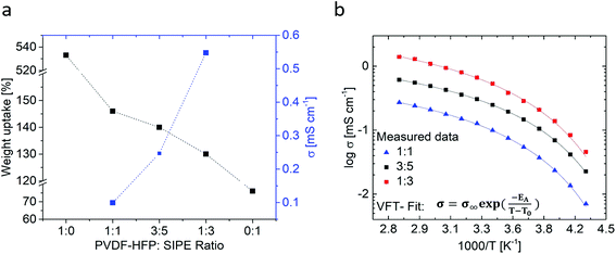
:![[thin space (1/6-em)]](https://www.rsc.org/images/entities/char_2009.gif) 1) for 16 hours. The swollen membranes exhibited sufficient mechanical stability and flexibility, affording bending without damage of the membranes. For all fabricated membranes, the corresponding solvent uptake (eqn (1)) and ionic conductivities were determined (Fig. 5a). The weight uptakes of neat PVDF-HFP as well as neat SIPE were determined as reference values (note however that the neat SIPE membrane is highly brittle and cannot be considered for application). Fig. 5b displays the temperature dependent ionic conductivities for the different membrane compositions.
1) for 16 hours. The swollen membranes exhibited sufficient mechanical stability and flexibility, affording bending without damage of the membranes. For all fabricated membranes, the corresponding solvent uptake (eqn (1)) and ionic conductivities were determined (Fig. 5a). The weight uptakes of neat PVDF-HFP as well as neat SIPE were determined as reference values (note however that the neat SIPE membrane is highly brittle and cannot be considered for application). Fig. 5b displays the temperature dependent ionic conductivities for the different membrane compositions.
As anticipated at a higher content of Li ions, the achievable ionic conductivity significantly increased at a higher content of the aromatic polymer within the blend. Upon changing the membrane compositions from 50 wt% SIPC and 50 wt% PVdF-HFP (1![[thin space (1/6-em)]](https://www.rsc.org/images/entities/char_2009.gif) :
:![[thin space (1/6-em)]](https://www.rsc.org/images/entities/char_2009.gif) 1) to 75 wt% SIPC and 25 wt% PVdF-HFP (1
1) to 75 wt% SIPC and 25 wt% PVdF-HFP (1![[thin space (1/6-em)]](https://www.rsc.org/images/entities/char_2009.gif) :
:![[thin space (1/6-em)]](https://www.rsc.org/images/entities/char_2009.gif) 3), an increase in ionic conductivity from 0.10 mS cm−1 to 0.52 mS cm−1 is observed at 20 °C, despite the fact that the actual solvent uptake is reduced from 147 wt% to 130 wt%. For all samples, the solvent uptake is comparatively low compared to a neat PVdF-HFP gel membrane taking up 533 wt% of solvent which is in good agreement with published data of PEO, PAN or PVdF-HFP based gel-type polymer electrolytes, where solvent weight uptakes of 300 wt% to 400 wt%, in some cases even up to 750 wt%, are feasible.55–60
3), an increase in ionic conductivity from 0.10 mS cm−1 to 0.52 mS cm−1 is observed at 20 °C, despite the fact that the actual solvent uptake is reduced from 147 wt% to 130 wt%. For all samples, the solvent uptake is comparatively low compared to a neat PVdF-HFP gel membrane taking up 533 wt% of solvent which is in good agreement with published data of PEO, PAN or PVdF-HFP based gel-type polymer electrolytes, where solvent weight uptakes of 300 wt% to 400 wt%, in some cases even up to 750 wt%, are feasible.55–60
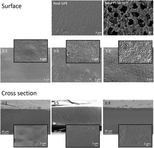
The solvent uptake in principle can be correlated with the morphology of the membranes. The morphologies of all blend membrane compositions (surface and cross section) as well as those of neat PVdF-HFP and SIPE membranes (surface) were investigated by SEM and are shown in Fig. 6. For the PVdF-HFP membrane pores of a few micrometer size were clearly visible whereas for the SIPE membrane no obvious pore structure could be observed (images at the top). The blend membranes differed from both of the neat membranes. All compositions had a dense structure showing no micropores in both the surface (middle) and cross sectional images (bottom), though nanopores could be assumed based on the respective high resolution images. The observed morphologies correlate well with the solvent uptake since for PVdF-HFP 500 wt% of solvent was taken up by the microporous structures while the dense blend membranes took up equally low amounts of about 130 wt% to 147 wt%, likely due to the absence of micropores. In the case of similar polymer blend systems composed of SIPE and PVdF-HFP both microporous40,43,45,47 and nanoporous46 morphologies were identified. For equally prepared membranes the morphology may be either highly porous or rather dense based on the chemical structure of the SIPE, depending on the compatibility of the two polymer blend compounds.26,41,42
Regarding the polymer membranes with composition 1![[thin space (1/6-em)]](https://www.rsc.org/images/entities/char_2009.gif) :
:![[thin space (1/6-em)]](https://www.rsc.org/images/entities/char_2009.gif) 3, ionic conductivities of 0.5 mS cm−1 and 1.08 mS cm−1 were achieved at 20 °C and 60 °C, respectively, which are among the highest values obtained for similar polymer blends comprised of PVdF-HFP and polysulfonamide based single Li-ion polymers.26,27,40–44 It should be noted that the ionic conductivity measured here is based on the conduction of only lithium ions as no residual solvent or impurities of the synthesis are present that could otherwise contribute to the overall ionic conductivity.
3, ionic conductivities of 0.5 mS cm−1 and 1.08 mS cm−1 were achieved at 20 °C and 60 °C, respectively, which are among the highest values obtained for similar polymer blends comprised of PVdF-HFP and polysulfonamide based single Li-ion polymers.26,27,40–44 It should be noted that the ionic conductivity measured here is based on the conduction of only lithium ions as no residual solvent or impurities of the synthesis are present that could otherwise contribute to the overall ionic conductivity.
All membranes show a rather comparable trend in ionic conductivity, reminiscent of Vogel–Fulcher–Tamann (VFT) behavior in the observed temperature range between −40 °C and 80 °C. Typically, fitting the curves with the VFT equation  yields values for Ea, an Arrhenius-type activation energy of ion transport, and for T0, the so-called Vogel temperature. The apparent activation energy of ion transport in all considered polymer blend compositions within the error margin of the measurement amounts to ≈3.4 ± 0.2 kJ mol−1, irrespective of the changes of the actual membrane composition. In the case of PEO/PPO-based “dry” single ion conducting polymer systems containing SO3− anchoring groups (that exhibit comparable charge carrier densities) 2 to 12 times higher apparent activation energies were obtained.32,61,62 For other gel-type electrolytes (containing lithium salt and multiple times higher solvent content), 2 times higher values were reported.63 However, a physically mixed blend polymer electrolyte strictly speaking does not reflect a single morphological “phase”, thus making a straightforward comparison of the derived data with other gel polymer electrolytes difficult.
Based on the obtained ionic conductivities σDC, the corresponding ion mobility μ and lithium ion self-diffusion coefficients D can be estimated from eqn (4)
 | (4) |
 | (5) |
![[thin space (1/6-em)]](https://www.rsc.org/images/entities/char_2009.gif) :
:![[thin space (1/6-em)]](https://www.rsc.org/images/entities/char_2009.gif) 3) (Fig. 7), in agreement with single ion conducting behavior. In the following, it is assumed that a lithium-ion transference number of 0.9 is valid for all considered samples comprising the lithiated polymer (5) irrespective of the utilized blend ratio. Correspondingly, for the determination of lithium self-diffusion coefficients (DLi+,calc) based on the conductivity values σDC, a correction factor is considered such that
3) (Fig. 7), in agreement with single ion conducting behavior. In the following, it is assumed that a lithium-ion transference number of 0.9 is valid for all considered samples comprising the lithiated polymer (5) irrespective of the utilized blend ratio. Correspondingly, for the determination of lithium self-diffusion coefficients (DLi+,calc) based on the conductivity values σDC, a correction factor is considered such that | (6) |
 | (7) |
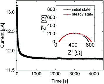 | ||
Fig. 7 Chronoamperometry and impedance measurement at 40 °C for the blend polymer membrane (sample 1![[thin space (1/6-em)]](https://www.rsc.org/images/entities/char_2009.gif) : :![[thin space (1/6-em)]](https://www.rsc.org/images/entities/char_2009.gif) 3). 3). | ||
The charge carrier density n is estimated based on stoichiometric and geometric parameters (thickness, area, and weight) of the rather homogenous SIPE membranes. The calculated values for n, DLi+,calc and μLi+,calc are collected in Table 1. Note that the estimated charge carrier density n in all cases has a similar order of magnitude known for PEO based electrolytes.32,64 At a higher content of single ion conducting polymer in the membrane n as well as the observable ionic conductivity increases, in addition to improved ion mobility or lithium ion diffusivity. This observation is not trivial, since ion mobility depends on both the charge carrier density n and ionic conductivity σ (cf.eqn (4)). If σ and n increase similarly, then no major change in ion mobility μ is expected (μ ∝ 1/n, σ). Therefore, the observed increase in ion mobility likely reflects morphology changes of the membranes, thereby facilitating better transport of the lithium ions.
| Sample | Temperature [°C] | n[×1020 cm−3] | μ Li+,calc [×10−6 cm2 V−1 s−1] | D Li+,calc [×10−11 m2 s−1] | D Li+,meas [×10−11 m2 s−1] | 1−α |
|---|---|---|---|---|---|---|
1![[thin space (1/6-em)]](https://www.rsc.org/images/entities/char_2009.gif) : :![[thin space (1/6-em)]](https://www.rsc.org/images/entities/char_2009.gif) 1 1 |
20 | 3.49 ± 0.03 | 1.60 ± 0.01 | 0.40 ± 0.01 | 1.03 ± 0.04 | 0.39 ± 0.01 |
| 40 | 2.42 ± 0.01 | 0.65 ± 0.01 | 3.26 ± 0.13 | 0.20 ± 0.01 | ||
3![[thin space (1/6-em)]](https://www.rsc.org/images/entities/char_2009.gif) : :![[thin space (1/6-em)]](https://www.rsc.org/images/entities/char_2009.gif) 5 5 |
20 | 4.27 ± 0.03 | 3.26 ± 0.01 | 0.82 ± 0.03 | 3.65 ± 0.12 | 0.22 ± 0.01 |
| 40 | 4.71 ± 0.02 | 1.27 ± 0.04 | 4.35 ± 0.25 | 0.29 ± 0.01 | ||
1![[thin space (1/6-em)]](https://www.rsc.org/images/entities/char_2009.gif) : :![[thin space (1/6-em)]](https://www.rsc.org/images/entities/char_2009.gif) 3 3 |
20 | 4.90 ± 0.03 | 6.11 ± 0.02 | 1.54 ± 0.01 | 4.62 ± 0.06 | 0.33 ± 0.01 |
| 40 | 9.17 ± 0.03 | 2.48 ± 0.01 | 8.43 ± 0.12 | 0.29 ± 0.02 |
The measured and calculated values of lithium-ion self-diffusion coefficients have a similar order of magnitude, exhibiting an increase with higher temperatures. Lithium ion diffusion was enhanced upon increasing the total lithium ion content within the polymer membrane; the obtained values for the lithium self-diffusion are within the range of self-diffusion coefficients known for PEO based systems. In the case of a gel-type electrolyte containing lithium salt (between 0.5 M and 1.5 M) lithium self-diffusion coefficients between 3 × 10⁻¹¹ and 6 × 10⁻¹¹ m2 s−1 at 22 °C were found, despite the fact that the electrolytes had significantly higher amounts of solvent uptake.65 For a solid SIPE, a self-diffusion coefficient of 1.2 × 10⁻¹¹ m2 s−1 at 20 °C was determined.32 From comparison of experimental and estimated self-diffusion coefficients, it is evident that DLi+,calc is lower than DLi+,meas derived from PFG-NMR. This is reasonable considering that for ionic conductivity measurements an external electric field is applied, so that primarily charged species are taken into account, whereas data from PFG-NMR reflect diffusion from all lithium species present in the electrolyte, including neutral clusters or aggregates as well as motion of otherwise associated lithium ions.66 In principle, the degree of ion association α may be determined from the ratio of the two diffusion coefficients, as reported for some liquid or polymer electrolytes suitable for lithium ion batteries,34,65,67–70 as dividing DLi+,calc by DLi+,meas yields (1 − α), the degree of Li ion dissociation (cf.Table 1). Note that the error margins given are based on error propagation of measurement inaccuracies and membrane geometry, where a homogenous distribution of the constituent polymer species within the electrolyte membrane was assumed. It is estimated that roughly 30% of the lithium ions are dissociated, though no further trends can be extracted for different samples or different temperatures.
The degree of ion dissociation strongly depends on the polymer chemistry, most importantly on the choice of the coordinating anionic group, where particularly sulfonamides allow for high degrees of ion dissociation.13,14 Nevertheless, lithium ion association may also occur with (other) functional groups of the polymer backbone or sidechains. For perfluoropolyether based electrolytes containing different end groups such as diol, dimethyl carbonate, ethoxy–diol, and ethoxy–dimethyl carbonate, respectively, and ca. 0.5 M LiTFSI as the electrolyte salt, corresponding degrees of lithium ion dissociation of 0.01 to 1 were reported, thereby clearly reflecting that lithium ion dissociation also depends on available polymer end groups (where polar end groups tend to increase the ion dissociation).67 Therefore, a further increase of lithium ion dissociation may be achieved by tailoring the structure of the considered single ion conducting polymer or by changing the blend partner.
3.2 Thermal stability
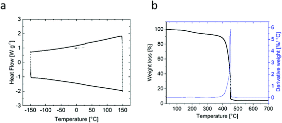
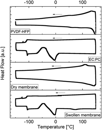
TGA and DSC measurements were performed to analyze the thermal behavior and stability of the lithiated polymer powder. No thermal phase transformation or glass transition occurred within the observed temperature range between −150 °C and 150 °C (Fig. 8a), while the TGA data (Fig.8b) exhibited significant weight losses and a sharp peak in the derivative at 449 °C (starting at 385 °C) indicating the onset of thermal degradation of the polymer.DSC measurements of the blend partner PVdDF-HFP, the solvent solution EC![[thin space (1/6-em)]](https://www.rsc.org/images/entities/char_2009.gif) :
:![[thin space (1/6-em)]](https://www.rsc.org/images/entities/char_2009.gif) PC (1
PC (1![[thin space (1/6-em)]](https://www.rsc.org/images/entities/char_2009.gif) :
:![[thin space (1/6-em)]](https://www.rsc.org/images/entities/char_2009.gif) 1, v/v), the “dry” and swollen membrane are shown in Fig. 9. For PVdF-HFP, a glass transition at −40 °C, an α-transition at 50 °C and a melting signal at 148 °C can be observed which are related to the thermal behavior of PVdF and are in good agreement with literature data.59,71 For the “dry” membrane, a melting signal at 143 °C was also observed, attributed to the melting temperature of the PVdF-HFP compound. A glass transition might be present at ≈−50 °C and would be reasonable due to the glass transition of PVdF-HFP, which is shifted due to blending, though it cannot be clearly observed. The solvent solution shows a glass transition at −105.91 °C, cold crystallization at −50 °C and melting at −5 °C.
1, v/v), the “dry” and swollen membrane are shown in Fig. 9. For PVdF-HFP, a glass transition at −40 °C, an α-transition at 50 °C and a melting signal at 148 °C can be observed which are related to the thermal behavior of PVdF and are in good agreement with literature data.59,71 For the “dry” membrane, a melting signal at 143 °C was also observed, attributed to the melting temperature of the PVdF-HFP compound. A glass transition might be present at ≈−50 °C and would be reasonable due to the glass transition of PVdF-HFP, which is shifted due to blending, though it cannot be clearly observed. The solvent solution shows a glass transition at −105.91 °C, cold crystallization at −50 °C and melting at −5 °C.
In the case of the swollen membrane, identical signals compared to the solvent solution are present, in addition to a signal at 73 °C related to PVdF-HFP. The addition of a plasticizer significantly reduces the melting temperature of the crystalline phase of PVdF-HFP.59 To estimate the influence of melting of the plasticized blend partner PVdF-HFP on the SIPE membrane, it was put onto a heating plate at 80 °C. The membrane increased its flexibility but maintained its shape, while ionic conductivity measurements of the SIPE performed between 80 °C and −40 °C demonstrated reversible behavior (Section 3.1). A disassembly of the respective cells revealed that membrane dimensions do not change during the conductivity measurements. Hence, it may be concluded that the observed behavior does not restrict the application of the membranes for temperatures higher than 73 °C. Nevertheless, in future studies other polymers will be considered as blend partners for membrane fabrication, possibly allowing for improved thermal stability of the polymer blends.
3.3 Electrochemical investigations
![[thin space (1/6-em)]](https://www.rsc.org/images/entities/char_2009.gif) :
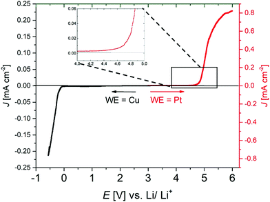
:![[thin space (1/6-em)]](https://www.rsc.org/images/entities/char_2009.gif) 3) is shown in Fig. 10. Oxidative stability, shown in red, was determined vs. the Pt electrode and reductive stability (black) vs. Cu (both at 20 °C). The reduction curve shows the plating signal of metallic lithium in the low electrode potential range ≈0 V vs. Li/Li+. In the oxidative part, starting from ca. 4.6 V vs. Li/Li+, an exponential increase in current density occurs, illustrating the onset of degradation of the SIPE membrane.
3) is shown in Fig. 10. Oxidative stability, shown in red, was determined vs. the Pt electrode and reductive stability (black) vs. Cu (both at 20 °C). The reduction curve shows the plating signal of metallic lithium in the low electrode potential range ≈0 V vs. Li/Li+. In the oxidative part, starting from ca. 4.6 V vs. Li/Li+, an exponential increase in current density occurs, illustrating the onset of degradation of the SIPE membrane.
Hence, the membrane is electrochemically stable up to 4.6 V vs. Li/Li+, implying compatibility with the most commonly applied active cathode materials, including LiCoO2, LiFePO4, LiNxMyCozO2 and LiNixCoyAlzO2, respectively.72,73 However, it should be noted that electrochemical stability investigations using rather inert working electrode materials may not directly reflect the actual electrochemical stability of the polymer electrolytes in application-oriented cell setups with typical cathode materials, e.g. due to different chemical environments.73 Therefore, additional cycling investigations are required to demonstrate the electrochemical stability of the electrolyte material within a given cell setup.
![[thin space (1/6-em)]](https://www.rsc.org/images/entities/char_2009.gif) :
:![[thin space (1/6-em)]](https://www.rsc.org/images/entities/char_2009.gif) PC (1
PC (1![[thin space (1/6-em)]](https://www.rsc.org/images/entities/char_2009.gif) :
:![[thin space (1/6-em)]](https://www.rsc.org/images/entities/char_2009.gif) 1)) while being electrochemically stable in the relevant voltage range of 3 V–4.3 V vs. Li/Li+. Fig. 12a and b show the cycling stability of NMC111/Li cells at 60 °C and 20 °C, respectively.
1)) while being electrochemically stable in the relevant voltage range of 3 V–4.3 V vs. Li/Li+. Fig. 12a and b show the cycling stability of NMC111/Li cells at 60 °C and 20 °C, respectively.
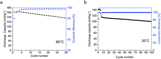 | ||
| Fig. 12 Cycle stability of the NMC111/lithium metal cell with the polymer blend electrolyte membrane (a) at 60 °C and (b) at 20 °C. | ||
The first five cycles were performed at C/20, whereas for later cycles a charge/discharge rate of C/10 was applied. At both temperatures, the first cycle exhibited a reduced coulombic efficiency of 79.9% at 60 °C and 82.8% at 20 °C, which is well known from NMC/liquid electrolyte cell systems, and often attributed to structural changes, and formation of a solid permeable interphase (SPI) on the cathode electrolyte interphase (CEI),76–78 as well as kinetically hindered re-lithiation of NMC.53,79,80 For the following cycles, high coulombic efficiencies of 97.5% (60 °C) and 99.2% (20 °C) were observed. Note that at elevated temperatures, degradation mechanisms may take place faster resulting in better capacity retention for cells cycled at 20 °C. The specific capacity of the cells is higher at 60 °C (163 mA h g−1 at 0.05C and 161 mA h g−1 at 0.1C) compared to 20 °C (142 mA h g−1 at 0.05C and 116 mA h g−1 at 0.1C), in agreement with higher ionic conductivity of the electrolyte membrane at increased temperatures. Indeed, the presented cycling investigations emphasize the high oxidative stability of the SIPE membranes, similarly to the data from linear sweep voltammetry (Fig. 10), thereby demonstrating the compatibility of the SIPE membrane with the NMC active material.
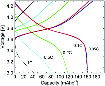
Fig. 13 shows the voltage profiles obtained by cycling the NMC111/Li metal cells at different C-rates. Typical voltage profiles for the NMC material with gradually decreasing or increasing specific capacity could be observed. The voltage profiles and specific capacity values at 0.05C and 0.1C are almost identical, despite higher over-potentials at increasing C-rates, leading to a decrease in specific capacity, e.g. due to interfacial resistances between the electrodes and SIPE membrane as well as due to rather low content of lithiated species within the cathode. Nevertheless, the actual rate performance should be further enhanced, e.g. by invoking different options such as optimization of the cathode composition or improvement of the electrolyte–electrode contacts. An analysis and better understanding of structure–interface relationships via spatially resolved (in operando) magnetic resonance imaging (MRI) techniques81 in principle could facilitate or contribute to the tailored design of electrolyte–electrode interfaces with improved cycling performance and cycling with higher C-rates, paving the way for even better electrochemical storage devices.
4. Conclusion
A new homopolymer is successfully prepared for application as a single ion conducting polymer electrolyte in lithium ion or lithium metal batteries. The polymer structure was tailored by introducing a functional C(CF3)2 group into the polymer backbone, thereby improving the solubility behavior such that an optimized synthesis affording a pure and solvent free product could be performed. Optimized gel-type blend polymer electrolyte membranes were produced by variation of the PVdF-HFP to single ion conducting polymer ratio, where higher fractions of SIPE significantly increased the achievable ionic conductivity and lithium ion diffusivity, despite the fact that the corresponding solvent uptake was reduced. A ratio of PVdF-HFP to the fluorinated single ion conducting polymer of 1![[thin space (1/6-em)]](https://www.rsc.org/images/entities/char_2009.gif) :
:![[thin space (1/6-em)]](https://www.rsc.org/images/entities/char_2009.gif) 3 was found to be ideal, resulting in flexible membranes with a high ionic conductivity of 0.5 mS cm−1 at 20 °C, a corresponding transference number of 0.9 (that indeed reflects single-ion conducting behavior) and a 7Li self-diffusion coefficient of 4.6 × 10⁻¹¹ m2 s−1 at 20 °C, respectively. Based on the obtained ion transport properties, a lithium ion dissociation degree of 30% was estimated. The long-term stability of the polymer electrolyte membrane against lithium metal and, in contrast to previous studies considering LFP as the cathode material, its applicability in NMC/lithium metal cells was demonstrated by cycling investigations, both performed at 20 °C as well as at 60 °C, highlighting the great potential of the introduced materials.
3 was found to be ideal, resulting in flexible membranes with a high ionic conductivity of 0.5 mS cm−1 at 20 °C, a corresponding transference number of 0.9 (that indeed reflects single-ion conducting behavior) and a 7Li self-diffusion coefficient of 4.6 × 10⁻¹¹ m2 s−1 at 20 °C, respectively. Based on the obtained ion transport properties, a lithium ion dissociation degree of 30% was estimated. The long-term stability of the polymer electrolyte membrane against lithium metal and, in contrast to previous studies considering LFP as the cathode material, its applicability in NMC/lithium metal cells was demonstrated by cycling investigations, both performed at 20 °C as well as at 60 °C, highlighting the great potential of the introduced materials.
Conflicts of interest
There are no conflicts to declare.Acknowledgements
Special thanks are offered to Debbie Berghus who performed the DSC and TGA measurements, Constantin Lürenbaum for the TXRF measurements and Alexander Pelz who performed the chronoamperometry and impedance measurements for the determination of transference numbers. Generous support provided by the German Federal Ministry of Education and Research (BMBF) project ‘Benchbatt’ (grant 03XP0047B) is gratefully acknowledged.References
- T. Placke, R. Kloepsch, S. Dühnen and M. Winter, Lithium ion, lithium metal, and alternative rechargeable battery technologies: the odyssey for high energy density, J. Solid State Electrochem., 2017, 21(7), 1939–1964 CrossRef CAS.
- R. Schmuch, R. Wagner, G. Hörpel, T. Placke and M. Winter, Performance and cost of materials for lithium-based rechargeable automotive batteries, Nat. Energy, 2018, 3(4), 267–278 CrossRef CAS.
- M. H. Ryou, Y. M. Lee, Y. Lee, M. Winter and P. Bieker, Mechanical surface modification of lithium metal: Towards improved Li metal anode performance by directed Li plating, Adv. Funct. Mater., 2015, 25(6), 834–841 CrossRef CAS.
- G. Bieker, M. Winter and P. Bieker, Electrochemical in situ investigations of SEI and dendrite formation on the lithium metal anode, Phys. Chem. Chem. Phys., 2015, 17(14), 8670–8679 RSC.
- S. S. Zhang, Problem, Status, and Possible Solutions for Lithium Metal Anode of Rechargeable Batteries, ACS Appl. Energy Mater., 2018, 1(3), 910–920 CrossRef CAS.
- W. Xu, et al., Lithium metal anodes for rechargeable batteries, Energy Environ. Sci., 2014, 7(2), 513–537 RSC.
- X. B. Cheng, R. Zhang, C. Z. Zhao and Q. Zhang, Toward Safe Lithium Metal Anode in Rechargeable Batteries: A Review, Chem. Rev., 2017, 117(15), 10403–10473 CrossRef CAS.
- L. Long, S. Wang, M. Xiao and Y. Meng, Polymer electrolytes for lithium polymer batteries, J. Mater. Chem. A, 2016, 4(26), 10038–10069 RSC.
- Q. Li, J. Chen, L. Fan, X. Kong and Y. Lu, Progress in electrolytes for rechargeable Li-based batteries and beyond, Green Energy & Environment, 2016, 1(1), 18–42 Search PubMed.
- A. Arya and A. L. Sharma, Polymer electrolytes for lithium ion batteries: a critical study, Ionics, 2017, 23(3), 497–540 CrossRef CAS.
- M. Winter, The Solid Electrolyte Interphase-The Most Important and the Least Understood Solid Electrolyte in Rechargeable Li Batteries, Z. Phys. Chem., 2009, 223(10–11), 1395–1406 CrossRef CAS.
- R. W. Schmitz, et al., Investigations on novel electrolytes, solvents and SEI additives for use in lithium-ion batteries: Systematic electrochemical characterization and detailed analysis by spectroscopic methods, Prog. Solid State Chem., 2014, 42(4), 65–84 CrossRef CAS.
- E. Strauss, S. Menkin and D. Golodnitsky, On the way to high-conductivity single lithium-ion conductors, J. Solid State Electrochem., 2017, 21(7), 1879–1905 CrossRef CAS.
- H. Zhang, et al., Single lithium-ion conducting solid polymer electrolytes: advances and perspectives, Chem. Soc. Rev., 2017, 46(3), 797–815 RSC.
- W. Cai, et al., Current Status and Future Prospects of Research on Single Ion Polymer Electrolyte for Lithium Battery Applications, J. Chin. Ceram. Soc., 2014, 1(1), 78–92 Search PubMed.
- J.-G. Zhang, W. Xu, and W. A. Henderson, Lithium Metal Anodes and Rechargeable Lithium Metal Batteries, vol. 249, 2017 Search PubMed.
- J.-N. Chazalviel, Electrochemical aspects of the generation of ramified metallic electrodeposits, Phys. Rev. A, 1990, 42(12), 7355–7367 CrossRef CAS.
- C. Brissot, M. Rosso and S. Lascaud, Dendritic growth mechanisms in lithium/polymer cells, J. Power Sources, 1999, 81, 925–929 CrossRef.
- M. Lu, J. Runt and P. Painter, An Infrared Spectroscopic Study of a Polyester Copolymer Ionomer Based on Poly(ethylene oxide) Mingfu, Macromolecules, 2009, 42(17), 6581–6587 CrossRef CAS.
- R. P. Doyle, et al., Poly(ethylenimine)-Based Polymer Blends as Single-Ion Lithium Conductors, Macromolecules, 2014, 47(10), 3401–3408 CrossRef CAS.
- J. K. Sihha and K. Maranas, Segmental dynamics and ion association in poly(ethylene oxide) based single ion conductors, Macromolecules, 2011, 44, 5381–5391 CrossRef.
- Z. Cai, Y. Liu, S. Liu, L. Li and Y. Zhang, High performance of lithium-ion polymer battery based on non-aqueous lithiated perfluorinated sulfonic ion-exchange membranes, Energy Environ. Sci., 2012, 5(2), 5690–5693 RSC.
- R. Meziane, J. P. Bonnet, M. Courty, K. Djellab and M. Armand, Single-ion polymer electrolytes based on a delocalized polyanion for lithium batteries, Electrochim. Acta, 2011, 57(1), 14–19 CrossRef CAS.
- H. R. Allcock, D. T. Welna and A. E. Maher, Single ion conductors-polyphosphazenes with sulfonimide functional groups, Solid State Ionics, 2006, 177(7–8), 741–747 CrossRef CAS.
- K. Matsumoto and T. Endo, Synthesis of networked polymers by copolymerization of monoepoxy-substituted lithium sulfonylimide and diepoxy-substituted poly(ethylene glycol), and their properties, J. Polym. Sci., Part A: Polym. Chem., 2011, 49(8), 1874–1880 CrossRef CAS.
- Y. Zhang, et al., Influence of Chemical Microstructure of Single Ion Polymeric Electrolyte Membranes on Performance of Lithium Ion Batteries, ACS Appl. Mater. Interfaces, 2014, 6, 17534–17542 CrossRef CAS.
- Y. Sun, et al., A Polyamide Single-Ion Electrolyte Membrane for Application in Lithium-Ion Batteries, Energy Technol., 2014, 2(8), 698–704 CrossRef CAS.
- Y. Zhang, et al., A class of sp3 boron-based single-ion polymeric electrolytes for lithium ion batteries, RSC Adv., 2013, 3(35), 14934 RSC.
- G. Xu, Y. Sun, R. Rohan, Y. Zhang, W. Cai and H. Cheng, A lithium poly(pyromellitic acid borate) gel electrolyte membrane for lithium-ion batteries, J. Mater. Sci., 2014, 49(17), 6111–6117 CrossRef CAS.
- X. G. Sun and J. B. Kerr, Synthesis and characterization of network single ion conductors based on comb-branched polyepoxide ethers and lithium bis(allylmalonato)borate, Macromolecules, 2006, 39(1), 362–372 CrossRef CAS.
- X. Wang, et al., Exploring polymeric lithium tartaric acid borate for thermally resistant polymer electrolyte of lithium batteries, Electrochim. Acta, 2013, 92, 132–138 CrossRef CAS.
- R. J. Klein, S. Zhang, S. Dou, B. H. Jones, R. H. Colby and J. Runt, Modeling electrode polarization in dielectric spectroscopy: Ion mobility and mobile ion concentration of single-ion polymer electrolytes, J. Chem. Phys., 2006, 124(14), 144903 CrossRef.
- B. Rupp, M. Schmuck, A. Balducci, M. Winter and W. Kern, Polymer electrolyte for lithium batteries based on photochemically crosslinked poly(ethylene oxide) and ionic liquid, Eur. Polym. J., 2008, 44(9), 2986–2990 CrossRef CAS.
- R. Rohan, et al., Melamine-terephthalaldehyde-lithium complex: A porous organic network based single ion electrolyte for lithium ion batteries, J. Mater. Chem. A, 2015, 3(9), 5132–5139 RSC.
- W. Van Schalkwijk and B. Scrosati, Advances in lithium-ion batteries, Kluwer Academic/Plenum Publishers, New York, 2002 Search PubMed.
- L. Imholt, D. Dong, D. Bedrov, I. Cekic-Laskovic, M. Winter and G. Brunklaus, Supramolecular Self-Assembly of Methylated Rotaxanes for Solid Polymer Electrolyte Application, ACS Macro Lett., 2018, 7(7), 881–885 CrossRef CAS.
- X. Cheng, J. Pan, Y. Zhao, M. Liao and H. Peng, Gel Polymer Electrolytes for Electrochemical Energy Storage, Adv. Energy Mater., 2018, 8(7), 1702184 CrossRef.
- R. C. Agrawal and G. P. Pandey, Solid polymer electrolytes: materials designing and all-solid-state battery applications: an overview, J. Phys. D: Appl. Phys., 2008, 41(22), 22301 CrossRef.
- R. Bouchet, et al., Single-ion BAB triblock copolymers as highly efficient electrolytes for lithium–metal batteries, Nat. Mater., 2013, 12(5), 452–457 CrossRef CAS.
- Y. Zhang, et al., Fluorene-containing cardo and fully aromatic single ion conducting polymer electrolyte for room temperature, high performance lithium ion batteries, ChemistrySelect, 2017, 2(26), 7904–7908 CrossRef CAS.
- Y. Chen, H. Ke, D. Zeng, Y. Zhang, Y. Sun and H. Cheng, Superior polymer backbone with poly(arylene ether) over polyamide for single ion conducting polymer electrolytes, J. Membr. Sci., 2017, 525, 349–358 CrossRef CAS.
- Y. Liu, et al., A mechanically robust porous single ion conducting electrolyte membrane fabricated via self-assembly, J. Membr. Sci., 2016, 507, 99–106 CrossRef CAS.
- Q. Pan, et al., Construction of a lithium ion transport network in cathode with lithiated bis(benzene sulfonyl)imide based single ion polymer ionomers, J. Power Sources, 2015, 283, 279–288 CrossRef CAS.
- W. Cai, Y. Zhang, J. Li, Y. Sun and H. Cheng, Single-Ion Polymer Electrolyte Membranes Enable Lithium-Ion Batteries with a Broad Operating Temperature Range, ChemSusChem, 2014, 7(4), 1063–1067 CrossRef CAS PubMed.
- Q. Pan, Y. Chen, Y. Zhang, D. Zeng, Y. Sun and H. Cheng, A dense transparent polymeric single ion conductor for lithium ion batteries with remarkable long-term stability, J. Power Sources, 2016, 336, 75–82 CrossRef CAS.
- Z. Li, et al., Single ion conducting lithium sulfur polymer batteries with improved safety and stability, J. Mater. Chem. A, 2018, 6(29), 14330–14338 RSC.
- Y. Zhang, et al., Highly porous single-ion conductive composite polymer electrolyte for high performance Li-ion batteries, J. Power Sources, 2018, 397, 79–86 CrossRef CAS.
- Z. Jiang, B. Carroll and K. M. Abraham, Studies of some poly(vinylidene fluoride) electrolytes, Electrochim. Acta, 1997, 42(17), 2667–2677 CrossRef CAS.
- H. Jia, et al., A propylene carbonate based gel polymer electrolyte for extended cycle life and improved safety performance of lithium ion batteries, J. Power Sources, 2018, 397, 343–351 CrossRef CAS.
- Q. Pan, Z. Li, W. Zhang, D. Zeng, Y. Sun and H. Cheng, Single ion conducting sodium ion batteries enabled by a sodium ion exchanged poly(bis(4-carbonyl benzene sulfonyl)imide-co-2,5-diamino benzenesulfonic acid) polymer electrolyte, Solid State Ionics, 2017, 300, 60–66 CrossRef CAS.
- S. Bisoi, A. K. Mandal, A. Singh and S. Banerjee, Gas separation properties of Troeger's base-bridged polyamides, e-Polymers, 2017, 17(4), 283–293 CAS.
- S. Bisoi, A. K. Mandal, V. Padmanabhan and S. Banerjee, Aromatic polyamides containing trityl substituted triphenylamine: Gas transport properties and molecular dynamics simulations, J. Membr. Sci., 2017, 522, 77–90 CrossRef CAS.
- J. Kasnatscheew, et al., The truth about the 1st cycle Coulombic efficiency of LiNi1/3Co1/3Mn1/3O2 (NCM) cathodes, Phys. Chem. Chem. Phys., 2016, 18(5), 3956–3965 RSC.
- J. Evans, C. A. Vincent and P. G. Bruce, Electrochemical measurement of transference number in polymer electrolytes, Polymer, 1987, 28(13), 2324–2328 CrossRef CAS.
- W. J. Li, C. L. Yang, Z. H. Li, Q. Z. Xiao, G. T. Lei and Y. H. Ding, A capsule-type gelled polymer electrolyte for rechargeable lithium batteries, RSC Adv., 2016, 6(53), 47833–47839 RSC.
- H.-S. Kim, P. Periasamy and S.-I. Moon, Electrochemical properties of the Li-ion polymer batteries with P(VdF-co-HFP)-based gel polymer electrolyte, J. Power Sources, 2005, 141(2), 293–297 CrossRef CAS.
- V. Gutmann, Empirical parameters for donor and acceptor properties of solvents, Electrochim. Acta, 1976, 21, 661–670 CrossRef CAS.
- H. S. Choe, J. Giaccai, M. Alamgir and K. M. Abraham, Preparation and characterization of poly(vinyl sulfone)-and poly(vinylidene fluoride)-based electrolytes, Electrochim. Acta, 1995, 40(13–14), 2289–2293 CrossRef CAS.
- S. Abbrent, J. Pletstil, D. Hlavata, J. Lindgren, J. Tegenfeldt and A. Wendsjo, Crystallinity and morphology of PVdF-HFP based gel electrolytes, Polymer, 2001, 42, 1407–1416 CrossRef CAS.
- C. Capiglia, Y. Saito, H. Kataoka, T. Kodama, E. Quartarone and P. Mustarelli, Structure and transport properties of polymer gel electrolytes based on PVdF-HFP and LiN(C2F5SO2)(2), Solid State Ionics, 2000, 131(3–4), 291–299 CrossRef CAS.
- M. C. Wintersgill and J. J. Fontanella, Polymer Electrolyte Reviews, Elsevier Applied Science, vol. 2, 1989 Search PubMed.
- D. Fragiadakis, S. Dou, R. H. Colby and J. Runt, Molecular mobility and Li+ conduction in polyester copolymer ionomers based on poly(ethylene oxide), J. Chem. Phys., 2009, 130(6), 064907 CrossRef.
- P. E. Stallworth, S. G. Greenbaum, F. Croce, S. Slane and M. Salomon, Lithium-7 NMR and ionic conductivity studies of gel electrolytes based on poly(methylmethacrylate), Electrochim. Acta, 1995, 40(13), 2137–2141 CrossRef CAS.
- S.-W. Wang and R. H. Colby, Linear Viscoelasticity and Cation Conduction in Polyurethane Sulfonate Ionomers with Ions in the Soft Segment-Single Phase Systems, Macromolecules, 2018, 51(8), 2757–2766 CrossRef CAS.
- K. Hayamizu, Y. Aihara, S. Arai and W. S. Price, Diffusion, conductivity and DSC studies of a polymer gel electrolyte composed of cross-linked PEO, γ-butyrolactone and LiBF4, Solid State Ionics, 1998, 107(1–2), 1–12 CrossRef CAS.
- P. Selter, S. Grote and G. Brunklaus, Synthesis and 7Li Ion Dynamics in Polyarylene-Ethersulfone-Phenylene-Oxide-Based Polymer Electrolytes, Macromol. Chem. Phys., 2016, 217(23), 2584–2594 CrossRef CAS.
- M. Chintapalli, et al., Relationship between Conductivity, Ion Diffusion, and Transference Number in Perfluoropolyether Electrolytes, Macromolecules, 2016, 49(9), 3508–3515 CrossRef CAS.
- N. Boden, S. A. Leng and I. M. Ward, Ionic-Conductivity and Diffusivity in Polyethylene Oxide Electrolyte-Solutions As Models for Polymer Electrolytes, Solid State Ionics, 1991, 45(3–4), 261–270 CrossRef CAS.
- M. Videa, W. Xu, B. Geil, R. Marzke and C. A. Angell, High Li[sup+] Self-Diffusivity and Transport Number in Novel Electrolyte Solutions, J. Electrochem. Soc., 2001, 148(12), A1352 CrossRef CAS.
- Z. Feng, K. Higa, K. S. Han and V. Srinivasan, Evaluating Transport Properties and Ionic Dissociation of LiPF6 in Concentrated Electrolyte, J. Electrochem. Soc., 2017, 164(12), A2434–A2440 CrossRef CAS.
- T. Yagi, M. Tatemoto and J. Sako, Transition Behavior and Dielectric Properties in Trifluoroethylene and Vinylidene Fluoride Copolymers, Polym. J., 1980, 12(4), 209–223 CrossRef CAS.
- J. Kasnatscheew, et al., Learning from electrochemical data: Simple evaluation and classification of LiMO2 type based positive electrodes for Li ion batteries by using a novel electrochemical analysis methodology, Energy Technol., 2017, 5(7), 1670–1679 CrossRef CAS.
- J. Kasnatscheew, B. Streipert, S. Röser, R. Wagner, I. Cekic Laskovic and M. Winter, Determining oxidative stability of battery electrolytes: validity of common electrochemical stability window (ESW) data and alternative strategies, Phys. Chem. Chem. Phys., 2017, 19(24), 16078–16086 RSC.
- K. Tasaki, Solvent decompositions and physical properties of decomposition compounds in Li-ion battery electrolytes studied by DFT calculations and molecular dynamics simulations, J. Phys. Chem. B, 2005, 109(7), 2920–2933 CrossRef CAS PubMed.
- V. Morizur, S. Olivero, J. R. Desmurs, P. Knauth and E. Duñach, Novel lithium and sodium salts of sulfonamides and bis(sulfonyl)imides: synthesis and electrical conductivity, New J. Chem., 2014, 38(12), 6193–6197 RSC.
- S. H. Kang, W. S. Yoon, K. W. Nam, X. Q. Yang and D. P. Abraham, Investigating the first-cycle irreversibility of lithium metal oxide cathodes for Li batteries, J. Mater. Sci., 2008, 43(14), 4701–4706 CrossRef CAS.
- J. Choi and A. Manthiram, Investigation of the irreversible capacity loss in the layered LiNi1/3Mn1/3Co1/3O2 cathodes, Electrochem. Solid-State Lett., 2005, 8(8), C102–C105 CrossRef CAS.
- S.-H. Kang, D. P. Abraham, W.-S. Yoon, K.-W. Nam and X.-Q. Yang, First-cycle irreversibility of layered Li–Ni–Co–Mn oxide cathode in Li-ion batteries, Electrochim. Acta, 2008, 54(2), 684–689 CrossRef CAS.
- J. Kasnatscheew, et al., Learning from Overpotentials in Lithium Ion Batteries: A Case Study on the LiNi1/3Co1/3Mn1/3O2 (NCM) Cathode, J. Electrochem. Soc., 2016, 163(14), A2943–A2950 CrossRef CAS.
- J. Kasnatscheew, et al., Changing established belief on capacity fade mechanisms: Thorough investigation of LiNi1/3Co1/3Mn1/3O2 (NCM111) under high voltage conditions, J. Phys. Chem. C, 2017, 121(3), 1521–1529 CrossRef CAS.
- K. Borzutzki and G. Brunklaus, Magnetic Resonance Imaging Studies of the Spatial Distribution of Charge Carriers, Annu. Rep. NMR Spectrosc., 2017, 91, 115–141 CrossRef CAS.
| This journal is © The Royal Society of Chemistry 2019 |

