
 Open Access Article
 This Open Access Article is licensed under a
 Creative Commons Attribution 3.0 Unported Licence
Deep pool water-impacts of viscous oil droplets†
Utkarsh
Jain
 *a,
Maziyar
Jalaal
a,
Detlef
Lohse
ab and
Devaraj
van der Meer
a
*a,
Maziyar
Jalaal
a,
Detlef
Lohse
ab and
Devaraj
van der Meer
a
aPhysics of Fluids Group and Max Planck Center Twente for Complex Fluid Dynamics, MESA+ Institute and J. M. Burgers Centre for Fluid Dynamics, University of Twente, P.O. Box 217, 7500AE Enschede, The Netherlands. E-mail: u.jain@utwente.nl; m.jalaal@utwente.nl
bMax Planck Institute for Dynamics and Self-Organization, Am Fassberg 17, 37077 Göttingen, Germany
First published on 20th May 2019
Abstract
We experimentally study the impacts of viscous, immiscible oil drops into a deep pool of water. Within the target liquid pool, the impacting drop creates a crater, whose dynamics are studied. It is found that the inertia of pool liquid and drop viscosity are the main factors that determine the crater's maximum depth, while the additional factor of mutual immiscibility between the drop and pool liquids leads to interesting interfacial dynamics along the oil–water interface. We discuss how this can change the crater dynamics in its retraction phase, making possible a type of double-entrainment, whereby a tiny air bubble is entrapped inside a water-entrained oil drop. Further, we report the observation of a type of ‘fingering’ that occurs along the oil-drop rim, which we discuss, arises as a remnant of the well-known crown-splash instability.
1 Introduction
Drop impacts on a deep pool of liquid1–6 and on different types of solid substrates7–9 have been an active subject of research for a long time. This finds its place in a wider tradition of the work on water entry comprehensively covered by Truscott et al.10 Drop impact studies differ from solid projectile impacts in that, in the former, the impacting projectile is deformable, which has also become of interest as evidenced by recent works of Hurd et al.11 and Jalaal et al.12Upon the impact of a drop on a deep liquid pool, a crater is formed below the free surface of the target, whose collapse can result in phenomena such as bubble entrainment and formation of a Worthington jet, depending on the physical conditions.6 To understand these common features, which constitute fundamental questions about cavity formation, collapse and jet formation, the experimental focus has been almost exclusively on impacts where the drop and pool consist of the same liquid. Having the drop impact on the same liquid makes the problem more tractable, and makes it possible to draw general conclusions about the above mentioned features. However, a more complex situation can exist in some natural processes and industrial applications, such as impacts of drops of different liquids. This is the focus of the present work. A real-world example of a viscous immiscible liquid impacting into water is connected to man-made accidents like oil spill from tankers. An investigation along this line was peformed by Murphy et al.,13 studying rain drop impacts on a deep pool of seawater covered by a thin oil layer.
Another example of naturally occurring accidents relevant to the present study can be oil blowouts from ocean surface.14 In particular, the impinging liquid (here, a drop) could be more viscous than the target liquid, which changes the types of underwater craters and their dynamics. Impacts of viscous, but miscible drops into water have been studied by Walker et al.15 and Sharma et al.,16 where glycerol was used as drop liquid. However, since glycerol is miscible with water, the two liquids undergo mixing during and after impact.
There has been surprisingly little work studying oil–water impacts. Some notable exceptions studying impacts on deep pool are the work by Lhuissier et al.,17 which principally studies the fragmentation of a water drop impacting silicone oil bath, and the work of Fujimatsu et al.18 which also studies water drop impact on oil bulk. The latter focuses on more traditional quantities of interest such as maximum diameter of drop spreading, and depths of the craters formed. More recent works by Che & Matar19 and Shaikh et al.20 have studied immiscible drop impacts, but on thin films.
Here, we use silicone oils as drop liquid, which are immiscible with water, and, in contrast to glycerol drops, maintain their bulk and surface properties throughout the impact process. This allows us to use a range of viscosities in the drop liquid, while keeping its surface tension and density nearly constant. We discuss the different crater formation and collapse processes in this configuration, and how it differs from a water drop impacting on water. The oil drop creates a crater in the water pool and spreads over its floor. This creates an extra liquid–liquid interface, which depending on the extent of viscous dissipation in the drop, can stretch over a small portion of, or over the entirety of the crater surface. We find that this can have interesting consequences for oil-drop entrainment, and also double-entrainment of an air bubble in the entrapped oil drop. The crater dynamics are further discussed quantitatively and its depth is compared against the predictions of a model based on flow within the target pool.
The paper is organised as follows: in Section 2 we discuss our experimental setup, the procedures followed and the experimental challenges. In Section 3.1, we discuss our observations of crater formation and collapse, and how they differ between oil-drop and water-drop impacting on water pool. The interaction between new oil–water interface and capillary waves during crater collapse leads to interesting types of entrainment, discussed in Section 3.2. Section 4 focusses on crater depth, discussing its dependence on crater potential energy and drop viscosity. Finally we report our observation of fingering along the drop rim in Section 5, followed by the conclusions in Section 6.
2 Experimental setup and range of parameters explored
The setup is shown in Fig. 1. It consists of a syringe pump, which is connected to a nozzle via thin tubing. Nozzles with different diameters were used to generate water and silicone oil drops of varying sizes. The syringe pump was operated at a quasi-static rate to ensure that the droplet which is formed at the opening of a nozzle gets detached by its own weight, and is not affected by the flow-rate of the liquid in the tubing. The generated drop, which is in the range of 3.1–4.4 mm in diameter, is then allowed to fall into a deep pool of stationary water which is 140 × 140 × 70![[thin space (1/6-em)]](https://www.rsc.org/images/entities/char_2009.gif) mm3 in volume. The subsequent events are recorded using high speed cameras (Photron Mini UX 100, 4–5 K fps) from a side to study the crater dynamics (Sections 3.1 and 4), and from the bottom (Photron SAX, 10–12 K fps) to study the detailed evolution of the oil–water interface (Section 5). The imaging from the side was done by the conventional means of using a brightly lit diffuser plate, which serves as the background for recording sub-surface crater behaviour. Imaging from the bottom similarly required a light diffuser. However, simply placing a diffuser in the optical path of the bottom-view camera would obstruct the falling drop in its path. Thus, light diffusion was achieved by using sheets of tracing paper, into which a hole was made to allow for the passage of falling drops. Cold light sources (Olympus ILP-1 and Sumita LS-M352A) were used to avoid heating the water in the target pool. All experiments were conducted at standard room temperature of 20 ± 0.5 °C. The liquids listed in Table 1 were used throughout the present study.
mm3 in volume. The subsequent events are recorded using high speed cameras (Photron Mini UX 100, 4–5 K fps) from a side to study the crater dynamics (Sections 3.1 and 4), and from the bottom (Photron SAX, 10–12 K fps) to study the detailed evolution of the oil–water interface (Section 5). The imaging from the side was done by the conventional means of using a brightly lit diffuser plate, which serves as the background for recording sub-surface crater behaviour. Imaging from the bottom similarly required a light diffuser. However, simply placing a diffuser in the optical path of the bottom-view camera would obstruct the falling drop in its path. Thus, light diffusion was achieved by using sheets of tracing paper, into which a hole was made to allow for the passage of falling drops. Cold light sources (Olympus ILP-1 and Sumita LS-M352A) were used to avoid heating the water in the target pool. All experiments were conducted at standard room temperature of 20 ± 0.5 °C. The liquids listed in Table 1 were used throughout the present study.
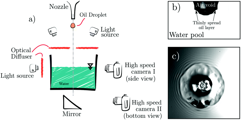 | ||
| Fig. 1 A schematic of the experimental setup is shown in panel a. Examples of side and bottom-view images are shown in panels b and c respectively. | ||
| Fluids | Viscosity μ (Pa s) | Density ρ (kg m−3) | Surface tension σ (mN m−1) | Manufacturer |
|---|---|---|---|---|
| Water | 0.89 × 10⁻³ | 1000 | 72 | Milli-Q |
| Silicone oil 35 cSt | 30 × 10−3 | 963 | 21 | Wacker Chemie AG |
| Silicone oil 50 cSt | 42.9 × 10⁻³ | 963 | 21 | Wacker Chemie AG |
| Silicone oil 100 cSt | 85.9 × 10⁻³ | 965 | 21 | Wacker Chemie AG |
| Silicone oil 200 cSt | 172.7 × 10⁻³ | 970 | 21 | Wacker Chemie AG |
Since the main drop detaches by its own weight and forms via a Rayleigh–Plateau instability, it is often accompanied by the creation of smaller satellite drops. It was observed that the number of satellite drops produced was greater for oils of smaller viscosity. In some experiments, the smaller drops would follow the main drop in impacting on the stationary water pool and interfere with the crater dynamics. Thus, only those experiments were analysed in which the satellite drops were either not produced at all, or trailed far enough behind the main drop such as to not interfere with the crater dynamics of interest. After each experiment, the oil drop was observed to rapidly spread all over the pool liquid surface due to its low interfacial tension with water.21 This contaminated both the target pool surface, and the container walls. As a result, each experiment required the container walls to be thoroughly cleaned, and the whole pool liquid to be replaced with a fresh volume of water. Both these reasons – the requirement of thorough cleaning of the target liquid containers, and the production of satellite drops, limited the number of experiments that could be conducted. The relevant non-dimensional numbers, Weber, Froude and Reynolds are defined as
 | (1) |
 | (2) |
The density and surface tension ratios between the drop–pool liquids remain at approximately constant values of 0.963–0.97 and 0.29, respectively (see Table 1) for all oil drop impact experiments, while the viscosity ratio between the drop liquid and water: μd/μw varies in the range 33.7–193.3. In the present study, a major focus is on the crater formation process after drop impact. Since crater formation is mainly an inertial process, for which the drop size sets the length scale, we choose the drop diameter D0 as the representative length scale in all the experiments. Throughout the study, the target pool consisted of purified water, whereas the drop liquid was changed to study the effect of drop viscosity on crater dynamics. Thus, it was deemed suitable to use the drop liquid viscosities to define the Reynolds number.
3 Qualitative description of the experimental results
3.1 Crater formation and collapse
Qualitative examples of a drop of water and silicone oils with different viscosities impacting onto a deep pool of water are shown in Fig. 2 (all with Fr ≈ 180) and 3 (all with Fr ≈ 300). A water drop impacting into a water pool penetrates the target pool and, in the initial stages, creates a bucket-shaped crater with steep walls (see Fig. 2a). The crater then rapidly grows into a roughly hemispherical shape and expands radially. These observations have been made since the earliest water drop-impact studies.4,22 An impacting drop of viscous oil, however, creates a notably different crater in the initial stages of impact. Instead of a flat bottomed crater where the pool liquid is exposed to air, we observe the crater bottom to have an oil–water interface, which has a slightly greater curvature than the latter from the earliest stages. For instance, see the early stages in Fig. 2b–e where a portion of an impacting viscous oil drop can be seen collected at the bottom of the crater. As the crater expands, the oil drop gets stretched out over the crater surface. It may cover a varying portion of the crater surface depending on its viscosity and the initial impact velocity. Soon after the initial stages of crater formation, the radial expansion of the crater and the downwards motion of the drop set a flow in the pool liquid, which was first reported by Engel4 based on observations of water-drop impacts on water pool. This flow in the target pool was understood to result from radial and tangential velocities of the pool liquid, and was used by Bisighini et al.23 to propose a potential flow model. It is seen that in the case of both – water drops impacting on water, and oil drops impacting on water with high Weber numbers (We > 1400 and Re > 100, Fig. 3a and b), the growing craters are found to be roughly hemispherical in shape for the most part of their expansion phase. Thus, flow in the pool, regardless of the drop liquid, is similar while there is an expanding hemispherical crater.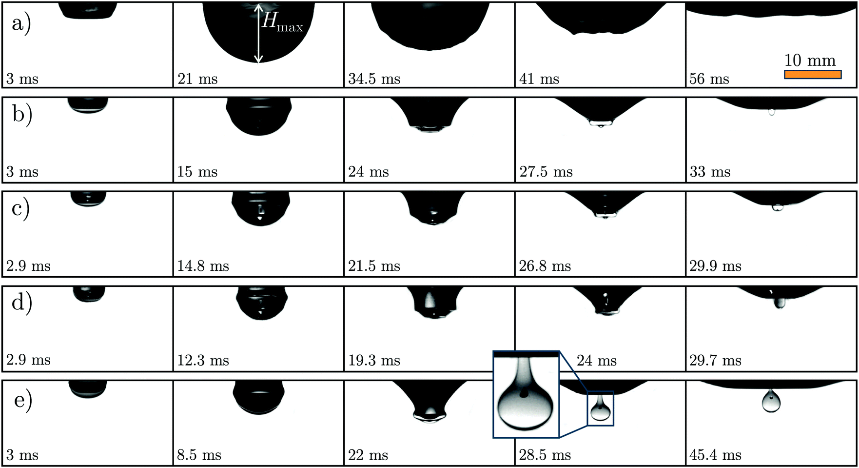 | ||
| Fig. 2 Typical sub-surface events after the deep-pool water impact of (a) Water drop with Fr = 168, We = 444, Re = 13333, corresponding to Ca = 0.033, (b) 35 cSt silicone oil drop with Fr = 178, We = 841, Re = 220, corresponding to Ca = 3.82, (c) 50 cSt silicone oil drop with Fr = 187, We = 868, Re = 156, corresponding to Ca = 5.56, (d) 100 cSt silicone oil drop with Fr = 172, We = 822, Re = 76, corresponding to Ca = 10.81 and (e) 200 cSt silicone oil drop with Fr = 177, We = 829, Re = 38, which corresponds to Ca = 21.82. A closer look at the experiment in panel e reveals an air-bubble entrained in the pool-entrained oil drop. See ESI† for the experimental video, and the main text for discussion. All the experiments shown above have comparable Froude numbers of ≈180. Despite this, there is a significant difference in the crater sizes between experiment (a) and experiments (b–e), which can be attributed to different sizes of the impinging drop. This difference in sizes of the impinging drop comes from how the drop is generated via a Rayleigh–Plateau instability. Since σwater is much larger than σsiliconeoil, the drops produced are larger in size. | ||
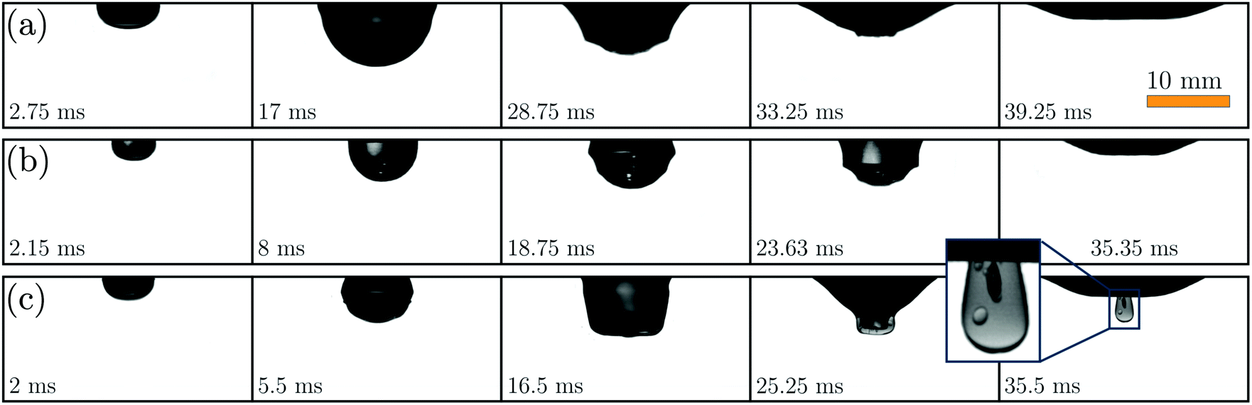 | ||
| Fig. 3 Typical sub-surface events after the deep-pool impact of (a) 35 cSt silicone oil with Fr = 287, We = 1502, Re = 302, corresponding to Ca = 4.97, (b) 100 cSt silicone oil with Fr = 306, We = 1490, Re = 103, corresponding to Ca = 14.47, (c) 200 cSt silicone oil with Fr = 312, We = 1424, Re = 50, corresponding to Ca = 28.48. All the experiments shown above have comparable Fr ≈ 300. As in Fig. 2, a closer look at the experiment in panel c reveals an air-bubble entrained in the pool-entrained oil drop. | ||
The impacting drop's energy can be used towards the creation of several phenomena such as the appearance of a crown splash, a wave swell that travels along the pool surface, and a sub-surface crater. Liow24 estimated that almost a third of the impacting drop's kinetic energy is converted to the crater's gravitational potential energy. This suggests that a significant portion of the drop energy is spent in other contemporary processes such as the creation and expansion of new liquid–liquid and liquid–air interfaces, creation and lifting up of a splash-crown, and viscous dissipation in the liquid components.25,26
The crater growth is finally arrested mainly by gravitational potential energy of the displaced fluid.4,27 Drops impacting with large Froude numbers create large craters, which in turn have large associated potential energy. To conclude, crater potential energy is one of the main energy sinks during the early stages of crater expansion process,28 and the main factor behind its subsequent retraction.
3.2 Crater retraction and entrainment
In later stages of crater growth, capillary waves appear on the crater walls which start from the raised sheet of liquid and move downwards, eventually focussing at the bottom. The waves travel inwards along the crater walls and deform the crater. Their effect on crater shapes and bubble entrapment in single-phase drop impact have been studied in detail in previous studies.29–33 In the experiments shown for oils of viscosity up to 100 cSt, the drop liquid was seen to spread over the whole crater surface for the given Froude numbers. Since the crater sizes are of the same order as capillary length scales, the timescales associated with these capillary waves travelling from the top of the liquid sheet to the crater bottom are comparable to the timescales associated with crater retraction resulting purely due to its gravitational potential. As a result, the two mechanisms often act together and play an important role in the collapse of a crater, namely in accelerating the collapse.33 In the experiments with oil drops presented here, the capillary waves are damped due to higher viscosity of the drop liquid34 as they travel towards the crater bottom. The wave convergence and the liquid components' mutual immiscibility makes the drop liquid accumulate at the bottom of the crater. The crater shapes that result due to capillary waves travelling along the initially smooth crater surfaces are shown in Fig. 2b–d and 3a–c. The presence of a viscous immiscible liquid at the center of the crater prevents a singular collapse of the air cavity,35,36 mitigating ‘regular’ bubble entrainment.34,37When a drop of higher viscosity (200 cSt, Fig. 2e and 3c) is allowed to fall into water, it spreads to a smaller extent than drops of lower viscosities impacted at similar Weber numbers. The importance of viscosity can also be seen by comparing the capillary (∼D0σ) and drag (μD0v) forces (see respective Ca) from the experiments shown in the Fig. 2 and 3. In our experiments, the value of the Capillary number changes from Ca ∼ ![[scr O, script letter O]](https://www.rsc.org/images/entities/char_e52e.gif) (10−2) for an impacting water droplet to Ca ∼ (10) for the highest viscosity of oil. Therefore in the latter case, viscosity can significantly damp the deformation of the impacting droplet. The extent to which the drop spreads can have very interesting consequences for oil entrainment. A new oil–water interface with a different surface tension is created along those parts of crater walls where the drop is in contact with water. This ‘oil-wetted’ area is surrounded by a ‘non-wetted’ water–air interface, which has a higher surface tension than the oil–water interface it surrounds.21 As a result, capillary waves occuring on this water–air interface move with a higher velocity than those that occur along oil–water interface. As with drops of lower viscosities (Fig. 2b–d and 3b–c), these waves are damped as they approach the oil–air interface nearer to the crater bottom. As the waves converge, they cause the oil-bulk to collect at the bottom, while the air cavity behind continues to collapse. In certain configurations (such as those shown in Fig. 2e and 3c) during this collapse, the air cavity is lined with an oil layer on the front side. Since the air cavity typically collapses via a ‘necking’ mechanism, this results in a small air bubble pinching off and getting entrained in the oil phase. Eventually, the oil phase detaches completely from the air-interface, leaving us with a doubly entrained bubble – a small air bubble entrained in a viscous oil drop, which is in turn entrained in the water bulk. A similar type of entrainment has been reported for a reactive drop-pool pair.38 Here, however, we show that the same type of double-bubble entrainment can also occur using a pair of immiscible, mutually non-reactive liquids.
(10−2) for an impacting water droplet to Ca ∼ (10) for the highest viscosity of oil. Therefore in the latter case, viscosity can significantly damp the deformation of the impacting droplet. The extent to which the drop spreads can have very interesting consequences for oil entrainment. A new oil–water interface with a different surface tension is created along those parts of crater walls where the drop is in contact with water. This ‘oil-wetted’ area is surrounded by a ‘non-wetted’ water–air interface, which has a higher surface tension than the oil–water interface it surrounds.21 As a result, capillary waves occuring on this water–air interface move with a higher velocity than those that occur along oil–water interface. As with drops of lower viscosities (Fig. 2b–d and 3b–c), these waves are damped as they approach the oil–air interface nearer to the crater bottom. As the waves converge, they cause the oil-bulk to collect at the bottom, while the air cavity behind continues to collapse. In certain configurations (such as those shown in Fig. 2e and 3c) during this collapse, the air cavity is lined with an oil layer on the front side. Since the air cavity typically collapses via a ‘necking’ mechanism, this results in a small air bubble pinching off and getting entrained in the oil phase. Eventually, the oil phase detaches completely from the air-interface, leaving us with a doubly entrained bubble – a small air bubble entrained in a viscous oil drop, which is in turn entrained in the water bulk. A similar type of entrainment has been reported for a reactive drop-pool pair.38 Here, however, we show that the same type of double-bubble entrainment can also occur using a pair of immiscible, mutually non-reactive liquids.
4 Maximum depth of crater
We find the crater depth H and radius R from experimental images by tracking its perimeter. Henceforth, all length scales discussed are non-dimensionalised with the respective initial drop size D0, and the timescales are non-dimensionalised with v/D0, such that non-dimensional time τ ≡ vt/D0. The timeseries for the crater depths H from some experiments with Fr ≈ 400 are shown in Fig. 4. The principal difference in the behaviours shown by different experiments lie in their approach to the point of crater's maximum depth. This appears to result from differences in viscosities of the drops, the more viscous ones having lower a Re. In experiments with small Re, the capillary waves along the crater walls can travel faster than the penetration speed of the crater itself, and can pose challenge in tracking the crater's boundaries. The waves' influence on the crater's depth can be seen in time series of 50 cSt and 100 cSt drops between τ = 10–15 in Fig. 4. They converge at the crater bottom and cause the bottom tip to vary around the point of maximum depth. The maximum crater depths Hmax, and the time taken to reach this depth, τmax are found from such experimental time series. | ||
| Fig. 4 A comparison of time series of experimentally determined crater depths (data points) with those obtained from Bisighini et al.23 model (solid lines with corresponding colour). Only 1-in-4 data points is shown in the experimental time-series for Hmax for clarity. The crater constants α0 used to calculate the curves from eqn (3) and (4) are 0.962 for water, 0.958 for 35 cSt silicone oil, 0.779 for 50 cSt silicone oil and 0.648 for 100 cSt silicone oil. The dashed line in the left panel corresponds to H/D0 = 0.44τ. We find that the model overpredicts Hmax as the impacting drops are made more viscous, which is quantitatively shown in the inset. | ||
4.1 Heuristic potential flow model
Here we describe a model to quantitatively describe the temporal evolution of the crater depths. It was reported by Engel et al.22 that, as in our experiments of impacting water drop on the pool, the crater formed in the target pool initially has a flat bottom. Soon it reaches a roughly-hemispherical shape, and a flow is established in the pool, which ‘appeared to be associated with the existence of both a radial and a tangential velocity in the liquid’.22 Bisighini et al.23 used these observations to model crater dynamics caused after the impact of a drop on a pool of the same liquid. They modelled the resulting flow in the pool as a linear superposition of flow potentials caused by flow past a sphere and a radially expanding sphere. The sphere, centred on O′, translates along the vertical coordinate ζ. Its velocity of translation is denoted by . Similarly, α is the radial coordinate, also centred on O′, along which the sphere expands with a speed expressed as
 ![[small alpha, Greek, dot above]](https://www.rsc.org/images/entities/i_char_e14c.gif) . These quantities are described in Fig. 5 and are non-dimensionalised by D0. The final equations of motion for the sphere are derived by balancing stresses at the crater interface for a thinly spread drop:
. These quantities are described in Fig. 5 and are non-dimensionalised by D0. The final equations of motion for the sphere are derived by balancing stresses at the crater interface for a thinly spread drop: | (3) |
 | (4) |
/α2Re and 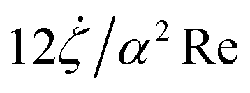 by considering the shear stresses in a thin layer of fluid along the free surface of the crater. The normal stress jump from viscous effects is ignored as the relevant layer of fluid is very thin. In our experiments, where there is a thin layer of another liquid (silicone oil) on the other side of the crater surface, the shear stresses are the same on either side of the oil–water interface in the crater.39 Therefore, the terms mentioned above can equally well be used to incorporate the viscous dissipation in a layer of oil which is thinly spread over the crater surface. We only concern with viscous dissipation in the oil phase as it is orders of magnitude greater than the dissipation in surrounding thin layers in water.
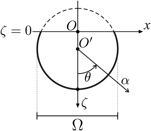 | ||
| Fig. 5 System of coordinates defined for the model contained in eqn (3) and (4). The system models a combination of flows caused by a sphere centred on O′, which translates downwards along ζ and expands along α. Ω is the diameter of the expanding crater. The original undisturbed free surface lies at ζ = 0. The figure has been adapted from ref. 23. | ||
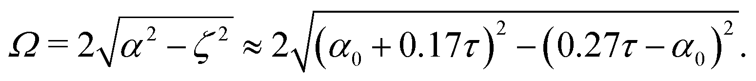
To this end, the system of eqn (3) and (4) can be solved numerically by supplementing with appropriate initial conditions and constants. Bisighini et al.23 calculate the crater's radial speed of expansion ≈ 0.17 and speed of sphere's translation  , for the initial stage of drop penetration (τ < 2). Their calculation leads to a simple asymptotic scaling of H/D0 = 0.44τ for small times. These values lead us to the following set of initial conditions
 | (5) |
 | (6) |
In the later stages (τ > 20 in Fig. 4), we find that the collapsing phase of the crater's bottom is consistently found to be steeper in the model than in the experiments. It can be seen in experimental images in Fig. 2 and 3, that regardless of whether a water drop or an oil drop impacts, there exist capillary waves that travel along the crater surface. As the crater begins to collapse due to its potential energy, these capillary waves travel in the opposite direction and effectively counter the buoyancy, thereby retarding the collapse of crater. The collapse is further slowed down in cases where a viscous drop impacts and creates the crater. Recall from Section 3.1 how the drop accumulates at the crater bottom during the retraction phase. Such an accumulation of a viscous fluid at the crater bottom would damp the capillary waves, but would also inevitably interfere with bouyancy-driven retraction of the crater and slow it down.
4.2 Inertial and viscous effects in determining
At τmax, the maximum depth of crater, Hmax/D0 can be modelled by balancing initial drop energy with the potential energy associated with the crater at its maximum size. Assuming the crater to have a hemispherical shape at the time of its maximum depth, and approximating a vanishing velocity field in the liquid at τmax, a relation between the maximum crater depth and Froude number can be derived:1,24,27| Hmax/D0 ∼ (Fr/ρ′)1/4, | (7) |
 | ||
| Fig. 6 Comparison between the a crater's depth and radius at τmax. Hmax and Rτmax are found to be roughly equal in size, which shows that the crater is approximately hemispherical in shape. Along the black line, Hmax = Rτmax. | ||
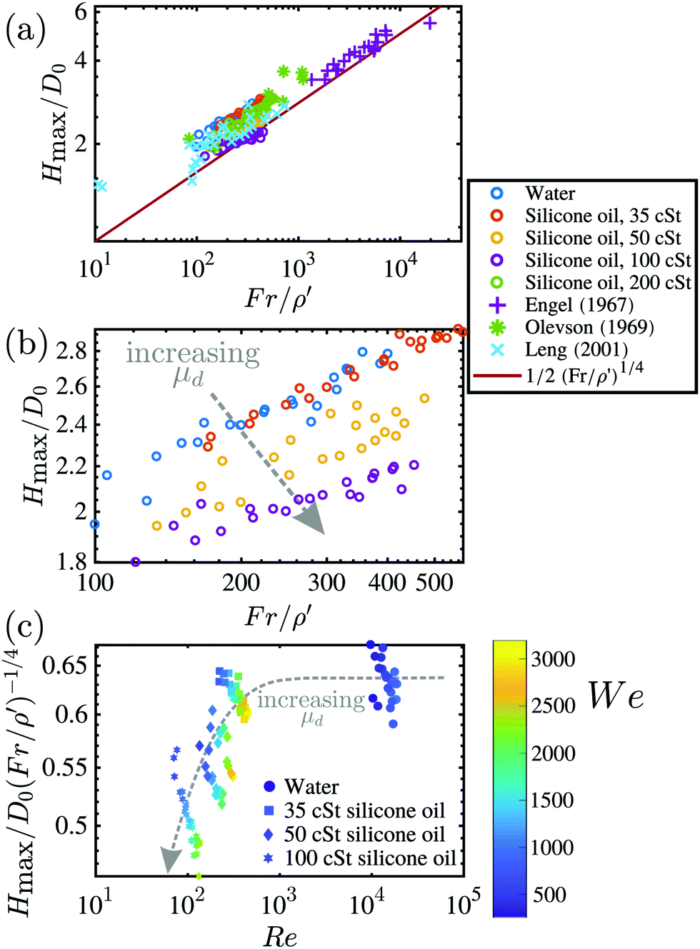 | ||
| Fig. 7 (a) Maximum depth of craters plotted against Froude number. Hmax/D0 resulting from oil drops impacting water roughly follow the scaling (Fr/ρ′)1/4. (b) A zoomed-in region of the plot in (a), and contains only the new results. The data here show a systematic trend in Hmax/D0vs. (Fr/ρ′) as a result of change in drop viscosity. Note the shared legend between subfigures (a) and (b). (c) The variation of Froude-scaling-compensated Hmax/D0 with Re is plotted. | ||
We find in Fig. 7a that our results for Hmax, along with previous works22,24,40 appear to follow the scaling shown in eqn (7). We conclude that for the drop parameters included in the figure, the inertia of the pool liquid plays a qualitatively similar role in determining the maximum depth of craters created by impacting oil droplets. From Fig. 7b, we see that for a given Fr/ρ′, that the greater the drop viscosity, the smaller the Hmax of the crater. It is clear from Fig. 2 and 3 that craters formed by drops of up to 100 cSt resemble the hemispherical craters formed by water drops. Oils with higher viscosities (here, 200 cSt) do not create such craters – they do not spread thinly over the crater surface, and consequently, do not satisfy the assumptions inherent in the model contained in eqn (3) and (4), and the scaling expressed in eqn (7). Thus, we only consider the data from oil viscosities up to 100 cSt in the following analysis.
Another interesting observation to be made from Fig. 7b is that the data from different drop viscosities have small differences in slope, exhibiting a small but systematic deviation from the (Fr/ρ′)1/4 scaling. We suspect this to be a result of the assumptions that are implicit in the derivation of this scaling. Additionally, this is also suspected to result from the so far un-investigated influence of viscosity on Hmax. The influence of μ on Hmax can be more systematically isolated and checked by compensating the Hmax/D0 results by (Fr/ρ′)1/4 scaling, and using another non-dimensional number, such as Re, which can capture the change in drop viscosity. Any deviations from Hmax/D0 ∼ (Fr/ρ′)1/4 scaling would expectedly continue to be visible in such a compensated plot. This is done in Fig. 7c, where the Froude-scaling is compensated-for in the measured crater-depths, and plotted against Re. This enables us to separate the roles played by Fr and Re in determining the crater depths.
From the results shown in Fig. 7c, we recover the same trend of Hmax with varying μ as shown in the adjoining figure, where Hmax are seen to be smaller for larger μ. This behaviour is also in agreement with our observation in earlier sections (specifically Fig. 4 and 6) where a larger drop viscosity was seen to result in shallower craters. A more viscous drop results in a shallower crater because there is larger amount of viscous dissipation in the drop itself, leaving lesser energy to be imparted to the pool liquid. From Fig. 7c we also see that impacts with a wide range of Weber numbers are distributed across a wide range of the shown parameter space, suggesting a weak correlation, if any, between We and Hmax.
5 Fingers along rim
The impact of an immiscible oil drop initially results in a typical crown splash above the initially stationary pool surface, which is accompanied by outwards-moving capillary waves, a growing crater and a wave swell. The splash crown consists of both drop and pool liquids, and depending on the drop's impact velocity, viscosity and interfacial surface tension with pool liquid, it might spread over the crater surface to a varying extent. The presence of drop liquid in the crown was recently also reported in the works by Che & Matar19 and Shaikh et al.,20 both of which studied water drop impacts on thin films of oil. Such a crown which is made of both the liquid components was termed a ‘compound crown’19 – its outer surface is composed of target pool liquid (in present study, water) and the inner surface is covered with the drop liquid (here, silicone oil). After ejection of tiny-drops by corona, the rim begins to stabilise as the sheet retracts back into the pool. At this stage, the remnant small-amplitude perturbations can still be seen along the compound-crown rim. These perturbations are quickly suppressed by high surface tension in the water phase but not so in the oil phase. As a result, the perimeter of retracting drop remains deformed – and these deformations are not smoothened out by surface tension as in water.As the crater retracts, the small deformations along oil-drop rim stretch into fingers, which can be seen due to a small difference in the two liquids' refractive indices. We recorded the experiments from the bottom (shown in Fig. 8; also see ESI† for an example of such an experiment) and counted the number of fingers Nf observable in a number of experiments. See also Fig. 10 in the Appendix where the same phenomena is shown from a different angle than bottom-view. In the experiment shown in Fig. 10, a small amount of milk powder was mixed with water to enhance the image contrast.
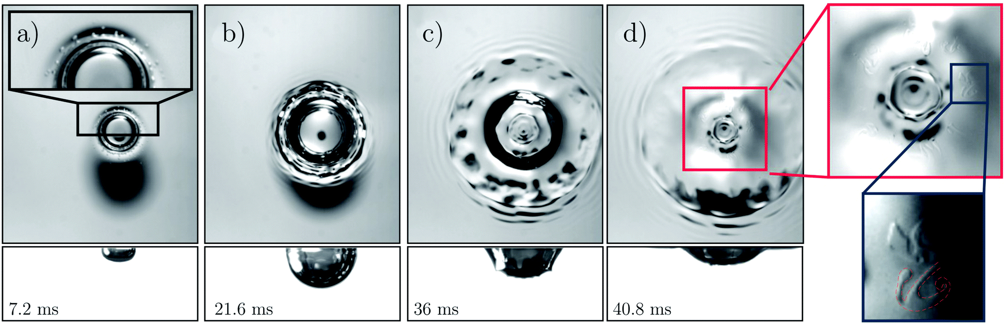 | ||
| Fig. 8 Impact of a 50 cSt silicone oil, 3.7 mm in diameter, at 4.22 m s−1 on a pool of stationary water. Top and bottom pictures correspond to bottom and side views, respectively. The corresponding non-dimensional numbers are We = 3028, Re = 175, Fr = 491, a Ca = 17.3. Upon impact, splashing occurs (highlighted in panel a) and a crater forms and grows (b). The crater eventually begins to retract (c and d) while capillary waves are formed at the crater and surface of the bath. We observe the fingers at this point (magnified in panel d) when the crater is retracting and forming a Worthington jet on the surface (not shown here). | ||
The number of fingers observed in each experiment was found to be closely correlated to the number of observable peaks along the rim of a retracting corona and always within a certain range of 10–15 as shown in Fig. 9. This was also the case in the recent paper of Shaikh et al.20 for drop impacts on thin films, where the number of fingers are always within a range of 11–19,41 independent of the non-dimensional groups. We therefore looked at the correlations in which the number of corona fingers is predicted. Marmanis and Thoroddsen42 proposed the so-called impact Reynolds number, ReI, based on the thickness of the crown walls δ ≈ (μdT/ρ)1/2, where T is the natural oscillation period of the droplet (as the deformation time scale). They eventually suggested that the number of fingers should be correlated as,
| Nf = αReβI, with ReI = We1/4Re1/2, | (8) |
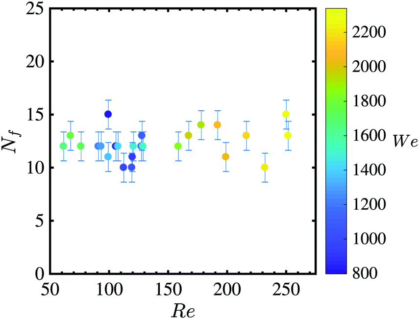 | ||
| Fig. 9 Number of fingers from a series of experiments over a range of Re and We, where Nf were counted as shown in Fig. 8. Error bars are the standard deviation over the shown data. | ||
Another approach to find the number of fingers is based on the Rayleigh–Taylor instability,44 assuming the cylindrical sheet of the liquid is accelerating in air (also see Zhang et al.45). Linear stability analysis leads to a dominant wave number of:
 | (9) |
 | (10) |
Note, in comparison with eqn (8), the equation above has different scalings for We and Re and has no fitting parameters. Nevertheless, similar to the previous correlation, for our experiments, the number of fingers using eqn (10) also only varies within the range of 11–22. The analyses above suggest the unchanged values of Nf (shown in Fig. 9) are most likely only due to limited parameter range available in the present experiments.
In the later stage of crater collapse, the retraction accelerates due to combined effects of gravitational retraction and capillary wave focussing. This causes the fingers to stretch significantly, while their tips may undergo tip-splitting. This makes the tips of the fingers appear like mushrooms (see the magnified views in panel d of Fig. 8). Note that since this stage of crater retraction is associated with rapid flow focussing, this observed tip-splitting may be ascribed to a shear instability due to a large jump in shear velocities occurring at the oil–water interface. Alternately, it could also be an outcome of viscous-fingering of the type produced in Taylor-Saffman instabilities, wherein such tip-splitting is a known mechanism of instability growth.
6 Conclusions
Here we reported the results from experiments studying the impacts of viscous immiscible oil drop on a deep pool of water. We use a range of viscosities of the oil, which, due to the added effect of immiscibility, result in a variety of interesting phenomena. An object of major interest in drop impacts is often the crater formed in the target pool. We find that the crater dynamics depend crucially on how the impinging drop behaves after impacting on the free surface. If the impinging drop spreads over the entirety of the crater surface, as is usually observed when the drop-target liquids are the same, the primary effect of increasing viscosity of the drop is that the crater is shallower. As the drop viscosity is increased further, it is unable to spread appreciably over the crater surface due to larger viscous dissipation. The drop's interaction with capillary waves makes the drop liquid accumulate at the crater bottom, and may result in its complete detachment from the water surface. In some cases, we also obtain double-entrainment of an air bubble within an entrained oil droplet. deeper understanding of this phenomenon can be of use in controlling various capsule-formation and encapsulation processes, particularly in pharmaceutical settings.46–49We employ the model proposed by Bisighini et al.23 to model the crater growth, where we include the viscous dissipation in the drop based on shear stress balance arguments. We find that the model works well for the early stages. It overpredicts the crater depths at the point of their maximum depth and predicts a faster collapse of the crater than is measured. The sources of disagreement between the model and experiments were identified and discussed.
The impact of an immiscible drop into a pool of another liquid results in the formation of a compound splash sheet – which consists of both the liquids risen above the initially calm pool surface. The rim of the sheet becomes hydrodynamically unstable and ejects tiny droplets. The deformations along the edge of the sheet during this stage are imposed on both the liquids which compose the crown. In our experiments, the perturbations along drop rim persist beyond the crater retraction stage, and get stretched into fingers. Such finger formation in the crown has been reported during water drop impacting on thin oil film experiments.19,20 We report that the same phenomenon occurs when an immiscible oil drop is impacts on a deep pool of water. A detailed understanding of this may give insights into fragmentation processes found in nature and industry. In this way, one may find the means to control the size distribution of daughter droplets produced via such violent fragmentation processes.17,20
Conflicts of interest
There are no conflicts to declare.Appendix: imaging fingers from top
To have a better understanding on the mechanism of the finger formation, we also performed the experiments in a slightly modified experimental setup, using a high speed camera to record from the top. However, it was often difficult to identify the oil fingers in these experiments due to very similar refractive indices of the two liquids.50 We attempted to improve the contrast between the two liquids by colouring the oil with a fat soluble dye up to the point of its saturation. However, given how thinly the oil layer is spread around the point of τmax, this method failed to provide a sufficiently large contrast difference. Thus, we resorted to colouring the water instead, and a small amount of milk powder was added to the water bulk to get a better contrast between the two phases. Fig. 10 shows a series of pictures in the setting explained above. See also ESI† for a video of the experiment discussed here. The images obtained provide a conclusive evidence for the presence of fingering. The milk powder slightly modified water properties, which resulted in a greater number of fingers than typically seen, and the mushroom-like structures shown in Fig. 8 could not develop in the shown experiment.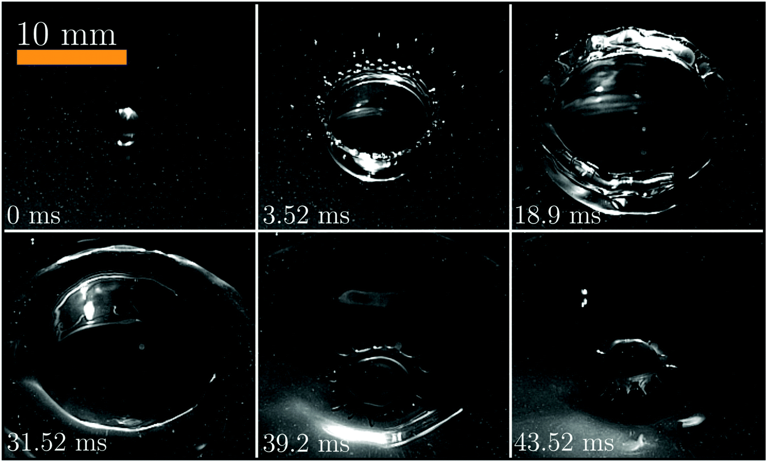 | ||
| Fig. 10 A 3.46 mm wide drop of 100 cSt silicone oil impacting on a pool of water at 3.5 m s−1. A small amount of milk powder was added to water to aid visualisation. The impacting drop spreads throughout the crater, whose edges destabilise leading to the well known splash-crown (3.52 ms). In the retraction stage (here 31.52 ms onwards), the perturbations along the crown-rim continue to exist along the retracting drop rim and get stretched into the fingers as shown at 39.2 ms. | ||
Acknowledgements
We would like to acknowledge funding from SLING (project number P14-10.1) which is (partly) financed by the Netherlands Organisation for Scientific Research (NWO). We would also like to thank V. Sanjay for helpful comments on an earlier version of the manuscript and J. Marston, A. Prosperetti and R. Krechetnikov for helpful discussion on the fingers results.References
- A. Prosperetti and H. N. Oǧuz, Annu. Rev. Fluid Mech., 1993, 25, 577–602 CrossRef.
- M. Rein, Fluid Dyn. Res., 1993, 12, 61–93 CrossRef.
- A. Worthington, A study of splashes, Longmans, Green, London, 1908, p. 129 Search PubMed.
- O. G. Engel, J. Appl. Phys., 1966, 37, 1798–1808 CrossRef.
- H. C. Pumphrey and P. A. Elmore, J. Fluid Mech., 1990, 220, 539–567 CrossRef CAS.
- A. Yarin, Annu. Rev. Fluid Mech., 2006, 38, 159–192 CrossRef.
- C. Josserand and S. Thoroddsen, Annu. Rev. Fluid Mech., 2016, 48, 365–391 CrossRef.
- A. L. Yarin, I. V. Roisman and C. Tropea, Collision phenomena in liquids and solids, Cambridge University Press, 2017 Search PubMed.
- C. Clanet, C. Béguin, D. Richard and D. Quéré, J. Fluid Mech., 2004, 517, 199–208 CrossRef.
- T. T. Truscott, B. P. Epps and J. Belden, Annu. Rev. Fluid Mech., 2014, 46, 355–378 CrossRef.
- R. C. Hurd, J. Belden, M. A. Jandron, D. T. Fanning, A. F. Bower and T. T. Truscott, J. Fluid Mech., 2017, 824, 912–930 CrossRef.
- M. Jalaal, D. Kemper and D. Lohse, J. Fluid Mech., 2019, 864, 596–613 CrossRef.
- D. W. Murphy, C. Li, V. d'Albignac, D. Morra and J. Katz, J. Fluid Mech., 2015, 780, 536–577 CrossRef.
- Y. Wu, Oil Spill Impacts: Taxonomic and Ontological Approaches, CRC Press, 2016 Search PubMed.
- T. W. Walker, A. N. Logia and G. G. Fuller, Exp. Fluids, 2015, 56, 106 CrossRef.
- V. Sharma, M. Szymusiak, H. Shen, L. C. Nitsche and Y. Liu, Langmuir, 2012, 28, 729–735 CrossRef CAS PubMed.
- H. Lhuissier, C. Sun, A. Prosperetti and D. Lohse, Phys. Rev. Lett., 2013, 110, 264503 CrossRef CAS PubMed.
- T. Fujimatsu, H. Fujita, M. Hirota and O. Okada, J. Colloid Interface Sci., 2003, 264, 212–220 CrossRef CAS PubMed.
- Z. Che and O. K. Matar, Soft Matter, 2018, 14, 1540–1551 RSC.
- S. Shaikh, G. Toyofuku, R. Hoang and J. Marston, Exp. Fluids, 2018, 59, 7 CrossRef.
- P. Than, L. Preziosi, D. Josephl and M. Arney, J. Colloid Interface Sci., 1988, 124, 552–559 CrossRef CAS.
- O. G. Engel, J. Appl. Phys., 1967, 38, 3935–3940 CrossRef.
- A. Bisighini, G. E. Cossali, C. Tropea and I. V. Roisman, Phys. Rev. E: Stat., Nonlinear, Soft Matter Phys., 2010, 82, 036319 CrossRef PubMed.
- L. J. Leng, J. Fluid Mech., 2001, 427, 73–105 CrossRef CAS.
- J. B. Lee, D. Derome, A. Dolatabadi and J. Carmeliet, Langmuir, 2016, 32, 1279–1288 CrossRef CAS PubMed.
- S. Wildeman, C. W. Visser, C. Sun and D. Lohse, J. Fluid Mech., 2016, 805, 636–655 CrossRef CAS.
- A. I. Fedorchenko and A.-B. Wang, Phys. Fluids, 2004, 16, 1349–1365 CrossRef CAS.
- G.-J. Michon, C. Josserand and T. Séon, Phys. Rev. Fluids, 2017, 2, 023601 CrossRef.
- H. N. Oǧuz and A. Prosperetti, J. Fluid Mech., 1990, 219, 143–179 CrossRef.
- H. N. Oǧuz and A. Prosperetti, J. Fluid Mech., 1991, 228, 417–442 Search PubMed.
- D. Morton, M. Rudman and L. Jong-Leng, Phys. Fluids, 2000, 12, 747–763 CrossRef CAS.
- W. Bouwhuis, X. Huang, C. U. Chan, P. E. Frommhold, C.-D. Ohl, D. Lohse, J. H. Snoeijer and D. van der Meer, J. Fluid Mech., 2016, 792, 850–868 CrossRef CAS.
- S. Gekle, A. van der Bos, R. Bergmann, D. van der Meer and D. Lohse, Phys. Rev. Lett., 2008, 100, 084502 CrossRef PubMed.
- Q. Deng, A. Anilkumar and T. Wang, J. Fluid Mech., 2007, 578, 119–138 CrossRef CAS.
- M. S. Longuet-Higgins, J. Fluid Mech., 1983, 127, 103–121 CrossRef.
- S. Gekle, J. M. Gordillo, D. van der Meer and D. Lohse, Phys. Rev. Lett., 2009, 102, 034502 CrossRef PubMed.
- B. Ray, G. Biswas and A. Sharma, Phys. Fluids, 2012, 24, 082108 CrossRef.
- Q. Deng, A. Anilkumar and T. Wang, J. Colloid Interface Sci., 2009, 333, 523–532 CrossRef CAS PubMed.
- S. S. Pegler and M. G. Worster, J. Fluid Mech., 2012, 696, 152–174 CrossRef CAS.
- K. Olevson, US Geological Survey Professional Paper, 1969, p. 189.
- Private communication with Jeremy Marston.
- H. Marmanis and S. T. Thoroddsen, Phys. Fluids, 1996, 8, 1344–1346 CrossRef CAS.
- H. Katsuragi, EPJ Web of Conferences, 2015, p. 02032.
- S. Chandrasekhar, Hydrodynamic and hydromagnetic stability, Courier Corporation, 2013 Search PubMed.
- L. V. Zhang, P. Brunet, J. Eggers and R. D. Deegan, Phys. Fluids, 2010, 22, 122105 CrossRef.
- T. Wang, I. Lack, M. Brissová, A. V. Anilkumar, A. Prokop, D. Hunkeler, R. Green, K. Shahrokhi and A. C. Powers, Nat. Biotechnol., 1997, 15, 358 CrossRef CAS PubMed.
- A. V. Anilkumar, I. Lacik and T. G. Wang, Biotechnol. Bioeng., 2001, 75, 581–589 CrossRef CAS PubMed.
- Y. Yeo, O. A. Basaran and K. Park, J. Controlled Release, 2003, 93, 161–173 CrossRef CAS PubMed.
- Y. Yeo, A. U. Chen, O. A. Basaran and K. Park, Pharm. Res., 2004, 21, 1419–1427 CrossRef CAS.
- Wacker Chemie AG, WACKER AK 100 SILICONE FLUID – Technical Data Sheet, Nov 2014.
Footnote |
| † Electronic supplementary information (ESI) available. See DOI: 10.1039/c9sm00318e |
| This journal is © The Royal Society of Chemistry 2019 |